Embed Size (px)
Citation preview

HVDC Classic – HVDC PLUSHVDC Classic HVDC PLUS
~ =DC
= ~AC Grid 1 AC Grid 2
Self-commutated Voltage-sourced converter (VSC)
Line-commutated current-sourced converter (LCC)
HVDC PLUSHVDC Classic
Semiconductor switches with turn-on and turn-off capability, e.g. IGBTs
Thyristors with turn-on capability only
( )( )
Page 1 May 2011 ET-PS Energy Transmission

General Features of VSC TechnologyGeneral Features of VSC Technology
•Grid access for weak AC networks (e.g. platforms)
•Independent control of active and reactive power
•Supply of passive networks (Black-Start Capability)pp y p ( p y)
•Good dynamic performance
•Low space requirements
Page 2 May 2011 ET-PS Energy Transmission

VSC Technology – Two level converterVSC Technology Two level converter
+Ud/2
U /2
-Ud/2
Desired voltageRealized voltage
High level of harmonic distortionHigh steep front voltages resulting in HF noise
Page 3 May 2011 ET-PS Energy Transmission
High steep front voltages resulting in HF noise and stress of component insulation
One of the many Multilevel ApproachesOne of the many Multilevel Approaches
(series connection of independent converters)
+Ud/2
UdUac
U /2-Ud/2
Small voltage steps
Low steep front voltagesExposed toDC Voltage
Page 4 May 2011 ET-PS Energy Transmission
Not very practical for high voltage applicationsdue to the high number of transformer windings
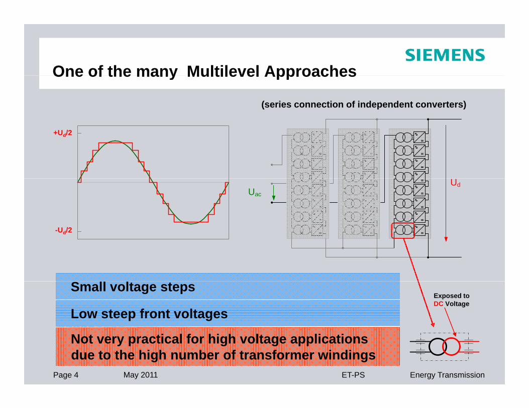
Modular Multilevel Converter - MMCModular Multilevel Converter MMC
+++
U /2
Ud
+
+
+
+
+
+
+
+
+
+Ud/2
Uac+
+
+
+
+
+
+
+
+
-Ud/2
Low level of harmonics and HF noise
+++d
Low level of harmonics and HF noise
Low switching losses
Modular arrangement with identical two
Page 5 May 2011 ET-PS Energy Transmission
Modular arrangement with identical two-terminal power modules
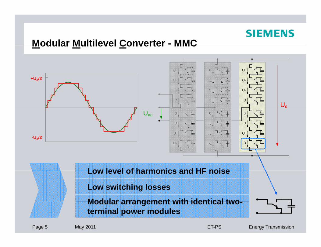
MMC topology - features and benefitsMMC topology features and benefits
Low semiconductor switching Low converter lossesfrequency
Low generation of harmonics
High modularity in hardware
Low converter losses
No filters required
High flexibility economicalHigh modularity in hardware and softwareUse of well-proven standard components
High flexibility, economical from low to high power ratings High availability of state-of-the-art components
Sinus shaped AC voltage waveforms
Easy scalability
Use of standard AC transformers
Low engineering effortsy y
Reduced number of primary components
g g
High reliability,low maintenance requirements
Page 6 May 2011 ET-PS Energy Transmission

Typical Arrangement for IGBT based HVDC Plus s stem (VSC)system (VSC)
+
+
+
+
M M
M
M
Converter Block
1000 MW
Converter Block
1000 MW
+
+
+
+
M M
Page 7 May 2011 ET-PS Energy Transmission

Isometric view Conventional Bipolar HVDC
Isometric view – Conventional Bipolar HVDC
Page 8 May 2011 ET-PS Energy Transmission

HVDC Plus Station 200MWHVDC Plus Station 200MW
Page 9 May 2011 ET-PS Energy Transmission

Benefits of HVDC PlusBenefits of HVDC Plus
Page 10 May 2011 ET-PS Energy Transmission
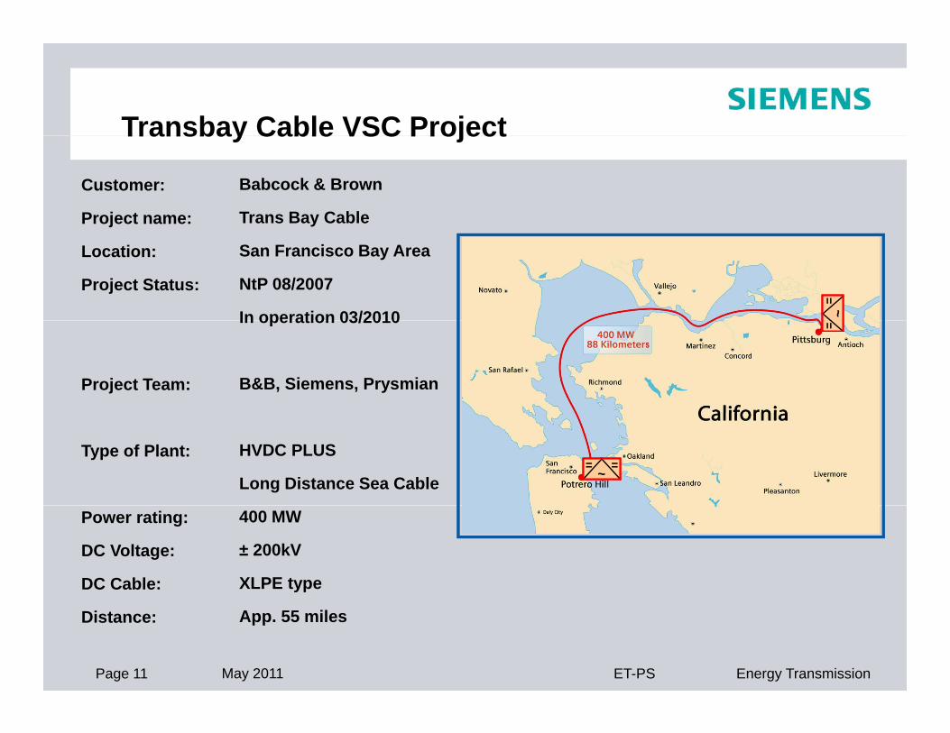
Transbay Cable VSC Project
Customer:
Project name:
Babcock & Brown
Trans Bay Cable
Transbay Cable VSC Project
Location:
Project Status:
San Francisco Bay Area
NtP 08/2007
In operation 03/2010 ~=
~=
Project Team:
In operation 03/2010
B&B, Siemens, Prysmian
==
Type of Plant: HVDC PLUS
Long Distance Sea Cable ~ == ~ ==
Power rating:
DC Voltage:
DC Cable:
400 MW
± 200kV
XLPE type
Page 11 May 2011 ET-PS Energy Transmission
Distance: App. 55 miles

Trans Bay Cable Project Overview
• Converter: Modular Multilevel HVDC PLUS Converter• Rated Power: 400MW @ AC Terminal Receiving End• DC Voltage: ± 200kV• Submarine Cable: Extruded Insulation Submarine Cable
PG&E Pittsburg
Substation
PG&E Potrero
Substation
< 1 mile ~50 miles< 1 mile < 1 mile < 3 miles
San Francisco Pittsburg
1 mile 50 miles 1 mile < 1 mile < 3 miles
San Francisco – San Pablo – Suisun Bays
Cables
AC/DCConverter
Station
Cables
AC/DCConverter
Station
Undersea DC Cables
ACAC
115 kV Substation
230 kV Substation
Page 12 May 2011 ET-PS Energy Transmission

Trans Bay Cable Project Layout of Converter StationConverter Station
Footprint:Footprint:150 x 110 m
Page 13 May 2011 ET-PS Energy Transmission

Typical DC-Transmission for Offshore WindparkTypical DC-Transmission for Offshore Windpark
G
G~
PlatformSwitchgear
Platform HVDC PLUS
G~
G~
Grid
OnshoreHVDC PLUS
Page 14 May 2011 ET-PS Energy Transmission