Embed Size (px)
Citation preview
N219
CONTENTS1 INSTALLATION PRECAUTIONS ............2
1-1 BEFORE INSTALLATION ................21-2 PARTS IDENTIFICATION ................31-3 KNOCKOUTS ..................................3
2 DETECTION AREA.................................42-1 OUTLINE OF DETECTION AREA ...42-2 HOW TO REDUCE THE LONG
RANGE DETECTION AREA ............62-3 HOW TO DEACTIVATE THE SHORT
RANGE DETECTION AREA ............83 PREPARATIONS ..................................10
3-1 TRANSMITTER PREPARATION ...103-2 BATTERY PREPARATION ............11
4 INSTALLATION (BATTERY AND TRANSMITTER) ...................................124-1 INSTALLING THE BATTERY .........124-2 INSTALLING THE TRANSMITTER
AND BATTERY BOX .....................155 INSTALLATION (BRACKET AND
MAIN UNIT) ..........................................165-1 INSTALLING WITH BRACKET ......165-2 ADJUSTING THE VERTICAL
ANGLE...........................................185-3 INSTALLING WITHOUT
BRACKET ......................................185-4 WIRING .........................................195-5 WALL TAMPER (OPTION) ............20
6 WALK TEST ..........................................227 SETTING ..............................................228 LED INDICATION .................................269 SPECIFICATIONS ................................27
9-1 SPECIFICATIONS .........................279-2 DIMENSIONS ................................28
HX-80NRAM Battery operated with 2 PIRs and anti-masking
Battery operated
Battery saving logic
Compatible with most wireless transmitter
Long distance detection area (24.0 m)
Flexible detection area setting with plates and flaps
Unique pyro element
Intelligent AND logic
Dual signal processing logic
Vegetation sway analysis logic
Digital anti-masking
•
•
•
•
•
•
•
•
•
•
NO.59-1620-0
INSTALLATION INSTRUCTIONSHigh Mount Outdoor Detector
HX-80NRAM
High Mount Outdoor Detector
HX-80NRAM
- 1 -
HX-80NRAM_EN.indd 1HX-80NRAM_EN.indd 1 2010/08/20 9:18:412010/08/20 9:18:41

1 INSTALLATION PRECAUTIONS
1-1 BEFORE INSTALLATION
Warning Failure to follow the instructions provided with this indication and improper handling may cause death or serious injury.
Caution Failure to follow the instructions provided with this indication and improper handling may cause injury and/or property damage.
The check mark indicates recommendation.The nix sign indicates prohibition.
Warning Warning Caution
Do not repair or modify product Keep product away from water Mount the unit scurely
Mounting height Keep the detector parallel to the ground.
Consider the direction a person is approaching from, as well as the detection area.
Install the detector in a place where it is free from false alarm factors. For example:
Sunlight and reflection• Heat source• Objects moving in the wind •
2.5 m – 3.0 m(8'2" – 9'10") Parallel Tilt
- 2 -
HX-80NRAM_EN.indd 2HX-80NRAM_EN.indd 2 2010/08/20 9:18:422010/08/20 9:18:42

1-2 PARTS IDENTIFICATION
(Transmitter and battery are not included.)
1-3 KNOCKOUTS
Bracket base Main unit
Bracket
LED indicatorLock screw* (M4 × 35 mm)
Lens
Base Terminals
Shaft cover
Cover
Lock screw
Anti-masking infrared LED
Screw (4 × 20 mm)
Battery box
AccessoriesBattery leads Velcro tapes Dummy battery
Alarm cable
PIR1(Do not touch)
PIR2(Do not touch)
For wall fastening/bracket fastening (installation pitch 83.5 mm (3.29"))
For main unit fasteningAdjustment screw
BracketMain unit
(Off-the-shelf) Universal magnet switch install position
For bracket Up-Down lock screw
Wiring Hole
For wall fastening
For switch box fastening
Do not touch
Up-Down lock screw
Wiring knockout
Wiring sponge padWiring Hole
Screw kitFor joint For wall mountingScrew (4 × 20 mm) Screw (4 × 20 mm)
*Lock screw attached on bracket base
- 3 -
HX-80NRAM_EN.indd 3HX-80NRAM_EN.indd 3 2010/08/20 9:18:432010/08/20 9:18:43

2 DETECTION AREA
a
bd
g
i
h
j
C
2-1 OUTLINE OF DETECTION AREA
Plate 2
Flap fix position indicator Plate fix position
indicator
Upper flap
Plate 1
Lower flap
- 4 -
HX-80NRAM_EN.indd 4HX-80NRAM_EN.indd 4 2010/08/20 9:18:432010/08/20 9:18:43

ba
ef
cj
gd
hi
ba
ef
cj
gd
hi
0.5
1.5
2.5
2.5
m (
8'2
")
(m)
48
12
16
20
24
(m)
1.0
6 4 2810
2.0
3.0
3.0
m (
9'1
0")
(m)
(ft.)
48
12
16
20
24
(m)
10
20
30
40
50
60
70
80
(ft.)
10
20
30
40
50
60
70
80
(ft.)
10
20
30
40
50
60
70
80
(ft.)
6 4 28
(ft.)
1.0
03 3
0
1.0
Top V
iew
Sid
e V
iew
(m)
(ft.)
48
12
16
20
24
(m)
DETECTION AREA (factory default)
Cau
tion>
>A
djus
t 1 c
lick
(1.2
5° u
pwar
d) fo
r 3.0
m (9
'10"
) hei
ght i
nsta
llatio
n. (R
efer
to 5
-2)
• Cau
tion>
>A
djus
t 2 c
licks
(2.5
° up
war
d) fo
r 2.5
m (8
'2")
hei
ght i
nsta
llatio
n. (R
efer
to 5
-2)
•
- 5 -
HX-80NRAM_EN.indd 5HX-80NRAM_EN.indd 5 2010/08/20 9:18:432010/08/20 9:18:43

2-2 HOW TO REDUCE THE LONG RANGE DETECTION AREATo adjust the LONG range of detection, set the upper and lower flaps as follows:
a
bd
g
i
h
j
C Flap fix position indicator
Upper flap
Lower flap
1 Pull out the flap.
a
b
g
i
C
Note>>If the lower flap is located at the factory default position, slide it out with your thumb.
2 Move the flap to the position that corresponds with the desired detection distance.
a
b
g
i
C
3 Push the flap until it clicks into position.
a
b
g
i
C
- 6 -
HX-80NRAM_EN.indd 6HX-80NRAM_EN.indd 6 2010/08/20 9:18:432010/08/20 9:18:43

Factory default
Factory default
ac
bd
2
3
4
3.0
m(9
'10")
6.5m(22')
5m
3.0
m(9
'10")
13m(42'8")
5m 10m
1 18m(60')
5m 10m 15m
3.0
m(9
'10")
3.0
m(9
'10")
10m(32'10")
5m
MASK
MASK
MASK
MASK
Upper position: a, Lower position: Factory default
Upper position: a, Lower position: b
Upper position: c, Lower position: b
Upper position: c, Lower position: d
PIR long range detection area reductionThe detection distance in the following table can be limited by combining the positions of the flap.Use the following table to determine the positions of the upper and lower flaps that set the required max. detection distance.NOTES:1. The distance may vary due to environmental conditions.2. Always walk test the detector to confirm the detection distance.
NOTE: Use only the following combinations for the flap settings.
24.0 m
(80')
c
a
b d
N.A.
N.A.13.0 m
(42'8")
18.0 m
(60')
N.A. 10.0 m
(32'10")
6.5 m
(22')
N.A.
1 2
3 4
Factory default
Lower
Upper
Factory default
- 7 -
HX-80NRAM_EN.indd 7HX-80NRAM_EN.indd 7 2010/08/20 9:18:442010/08/20 9:18:44
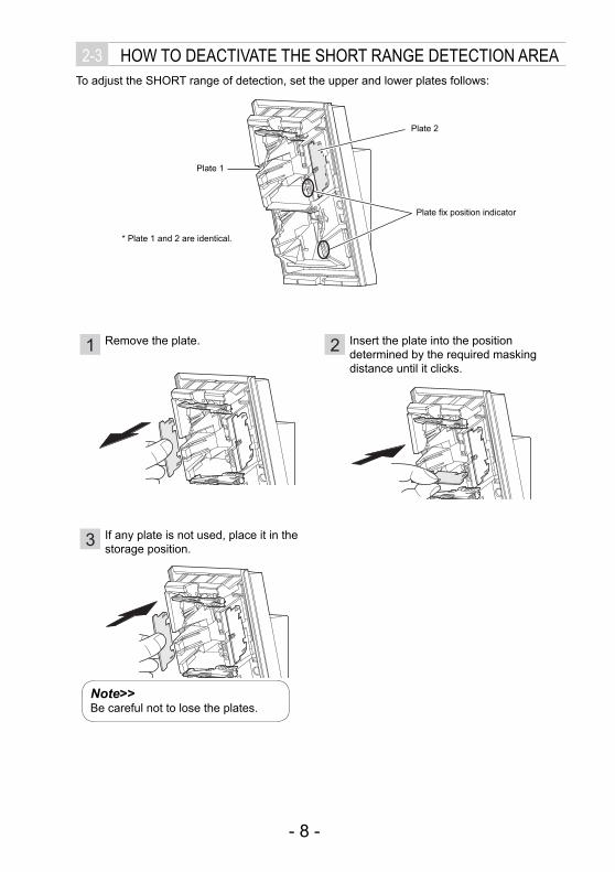
2-3 HOW TO DEACTIVATE THE SHORT RANGE DETECTION AREATo adjust the SHORT range of detection, set the upper and lower plates follows:
Plate 2
Plate fix position indicator
Plate 1
* Plate 1 and 2 are identical.
a
bd
g
i
h
j
C
1 Remove the plate.
a
b
g
i
C
2 Insert the plate into the position determined by the required masking distance until it clicks.
a
b
g
i
C
3 If any plate is not used, place it in the storage position.
a
b
g
i
C
Note>>Be careful not to lose the plates.
- 8 -
HX-80NRAM_EN.indd 8HX-80NRAM_EN.indd 8 2010/08/20 9:18:442010/08/20 9:18:44

g
i
j h
N.A.
3
N.A.
1
N.A.
Factorydefault
2
4
N.A.
PIR short range detection area deactivationUse the following table to determine the positions of the plates that set the required masked area.
NOTE: Use only the following combinations for the plate settings.
gi
hj
Lower
UpperNot used
Not used
1
3.0
m(9
'10")
24m(80')
5m 10m 20m
2
3.0
m(9
'10")
24m(80')
5m 10m 20m
3
3.0
m(9
'10")
24m(80')
5m 10m 20m
4
3.0
m(9
'10")
24m(80')
5m 10m 20m
MASK
MASK
MASK
MASK Upper position: Factory default, Lower position: j
Upper position: i, Lower position: j
Upper position: i, Lower position: h
Upper position: g, Lower position: h
- 9 -
HX-80NRAM_EN.indd 9HX-80NRAM_EN.indd 9 2010/08/20 9:18:452010/08/20 9:18:45
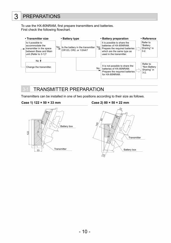
3 PREPARATIONS
To use the HX-80NRAM, first prepare transmitters and batteries.First check the following flowchart.
3-1 TRANSMITTER PREPARATIONTransmitters can be installed in one of two positions according to their size as follows.
122
33
80
140
15
22
• Battery preparationIs it possible to accommodate the transmitter in the space between Base and Main unit (Refer to 3-1)?
Change the transmitter.
Is the battery in the transmitter CR123, CR2, or 1/2AA?
It is possible to share the batteries of HX-80NRAM. Prepare the required batteries which are the same type as used in the transmitter.
Refer to “Battery Sharing” in 3-2.
It is not possible to share the batteries of HX-80NRAM. Prepare the required batteries for HX-80NRAM.
Refer to “Non Battery Sharing” in 3-2.
• Transmitter size • Battery type • Reference
Yes Yes
No
No
Transmitter
Battery box
Transmitter
Battery box
Case 1) 122 × 50 × 33 mm Case 2) 80 × 50 × 22 mm
- 10 -
HX-80NRAM_EN.indd 10HX-80NRAM_EN.indd 10 2010/08/20 9:18:452010/08/20 9:18:45

3-2 BATTERY PREPARATION-Battery Sharing HX-80N
(Refer to 4-1.)
Power supplied is available from battery box to power HX-80NRAM and the transmitter.
-Non Battery Sharing HX-80N(Refer to 4-1.)
Separate batteries for HX-80NRAM and the transmitter.
Note that battery type should be the same as that
used for the transmitter.
Type CR123A CR2 1/2AA 1/2AA(*1)
Voltage 3.0VDC 3.0VDC 3.6VDC 7.2VDC(*1)Number of cells to use 3 cells 3 cells 3 cells 6 cells(*1)
*1: 3.6 VDC 1/2 AA battery in series.
Note that battery type should be the same as that
used for the transmitter.
Type CR123A CR2 1/2AA 1/2AA(*1)
Voltage 3.0VDC 3.0VDC 3.6VDC 7.2VDC(*1)Number of cells to use 3 cells 3 cells 3 cells 6 cells(*1)
*1: 3.6 VDC 1/2 AA battery in series.
Type CR123A
Voltage 3.0VDCNumber of cells to use 3 cells
If CR123A battery cells are unavailable, three CR2 battery cells (3.0 VDC) can be substituted. Do not use 1/2AA batteries.* Do not use the attached dummy batteries or battery
lead.
Type CR123A
Voltage 3.0VDCNumber of cells to use 3 cells
If CR123A battery cells are unavailable, three CR2 battery cells (3.0 VDC) can be substituted. Do not use 1/2AA batteries.* Do not use the attached dummy batteries or battery
lead.
Transmitter HX-80NRAM Battery box
Dummy battery
ALARM POWEROUTPUT
POWER INPUT
HX-80NRAM Main unit
Transmitter HX-80NRAM Battery box
ALARM POWEROUTPUT
POWER INPUT
HX-80NRAM Main unit
TROUBLEOUTPUT
Not used
- 11 -
HX-80NRAM_EN.indd 11HX-80NRAM_EN.indd 11 2010/08/20 9:18:452010/08/20 9:18:45

-Installation procedure
4 INSTALLATION (BATTERY AND TRANSMITTER)
DETERMINING THE DETECTION LENGTH
INSTALLING THE BATTERY-Battery Sharing-Non Battery Sharing
INSTALLING THE TRANSMITTER AND BATTERY BOX
1 Remove the battery box from the main unit. 2 Remove the battery box cover.
4-1 INSTALLING THE BATTERY-Battery Sharing
WarningDo not use batteries of different capacities (i.e.: mixing new and used batteries) or of different manufacturers and/or types together. Not observing the above may result in an explosion, leakage of electrolyte, emission of toxic gases or other outcomes that may be harmful to people and property.
Open the claws (at 2 places) slightly.
Lift and remove
Open the claws (at 2 places).
Disengage the bosses (at 2 places).
Pull
- 12 -
HX-80NRAM_EN.indd 12HX-80NRAM_EN.indd 12 2010/08/20 9:18:462010/08/20 9:18:46

3 Mount batteries and place cover into correct position using indicator on side of battery box. Hook the cover firmly by the claws on the right and left sides.
4 Open the transmitter cover and remove the battery.
5 Place the battery lead (included in the set) and a dummy battery in the battery case of transmitter.
CR123A
CR2
1/2AA
1/2AA
* Twist and cut off the portion that fits the applicable battery type.
6 Connect the alarm cable to the transmitter and close the cover.
CR123A×3 (3.0VDC) 1/2AA×3 (3.6VDC)CR2×3 (3.0VDC) 1/2AA×6 (7.2VDC×3) (*1)
*1: 3.6 VDC 1/2 AA battery in series.
BATTERY LEAD (red)BATTERY LEAD (black)
Dummy battery
Put the alarm wire outside through the wiring hole
Transmitter
Alarm cable
Dummy battery
Caution>>To avoid short circuit, do not connect ends of red and black wires together.
- 13 -
HX-80NRAM_EN.indd 13HX-80NRAM_EN.indd 13 2010/08/20 9:18:462010/08/20 9:18:46

1 Remove the battery box from the main unit. 2 Remove the battery box cover.
3 After installing the batteries, check the guide on the side and install the cover. Hook the cover firmly by the claws on the right and left sides.
CR123A CR2
4 Connect the alarm cable to the transmitter and close the cover.
Open the claws (at 2 places) slightly.
Lift and remove
Open the claws (at 2 places).
Disengage the bosses (at 2 places).
Pull
Put the alarm wire outside through the wiring hole
Transmitter
Alarm cable
-Non Battery Sharing Arrange 3 cells each of CR-123A (recommended) or CR2.
WarningDo not use batteries of different capacities (i.e.: mixing new and used batteries) or of different manufacturers and/or types together. Not observing the above may result in an explosion, leakage of electrolyte, emission of toxic gases or other outcomes that may be harmful to people and property.
Caution>>To avoid short circuit, do not connect ends of red and black wires together.
- 14 -
HX-80NRAM_EN.indd 14HX-80NRAM_EN.indd 14 2010/08/20 9:18:482010/08/20 9:18:48
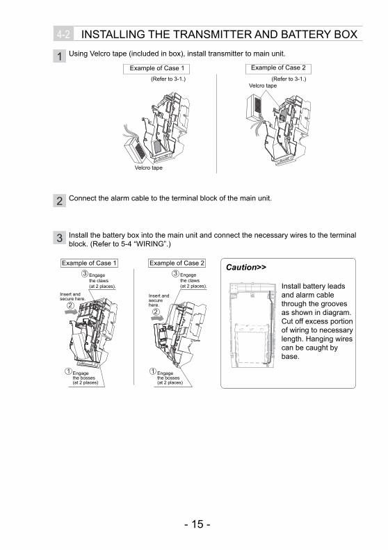
3 Install the battery box into the main unit and connect the necessary wires to the terminal block. (Refer to 5-4 “WIRING”.)
2
1
3
2
1
3Example of Case 1 Example of Case 2
Engage the claws (at 2 places).
Engage the claws (at 2 places).
Insert and secure here. Insert and
secure here.
Engage the bosses(at 2 places)
Engage the bosses(at 2 places)
Install battery leads and alarm cable through the grooves as shown in diagram.Cut off excess portion of wiring to necessary length. Hanging wires can be caught by base.
Caution>>
4-2 INSTALLING THE TRANSMITTER AND BATTERY BOX
1 Using Velcro tape (included in box), install transmitter to main unit.
2 Connect the alarm cable to the terminal block of the main unit.
Velcro tape
Example of Case 1 Example of Case 2
(Refer to 3-1.) (Refer to 3-1.)Velcro tape
- 15 -
HX-80NRAM_EN.indd 15HX-80NRAM_EN.indd 15 2010/08/20 9:18:492010/08/20 9:18:49

5-1 INSTALLING WITH BRACKETUsing the bracket makes it possible to adjust the unit horizontally by ±90°.In cases where the ground is uneven and therefore not parallel with the base of the unit, it is possible to adjust the unit vertically by ±20°.
1 Remove the Up-Down lock screw. 2 Push the shaft cover clip straightly to remove the shaft cover.
Push with suitable tool.e.g. small screwdriver
Shaft cover
Shaft cover clip
20°20°
Caution>>Do not change the detection length with bracket. Use the flaps and plates to adjust the detection length.
90° 90°
Use the bracket for normal installation. The unit may be installed directly on the wall, without the bracket, only if the following three conditions are met;
The mounting height is less than 3 m (9'10").Horizontal adjustment is not necessary.The ground must be level.
•••
5 INSTALLATION (BRACKET AND MAIN UNIT)
- 16 -
HX-80NRAM_EN.indd 16HX-80NRAM_EN.indd 16 2010/08/20 9:18:492010/08/20 9:18:49

3 Loosen the adjustment screw two turns. 4 Determine the horizontal direction (left or right) of the detector before installing the bracket on the wall.
5 Open the wiring knockout and Up-Down lock screw knockout for the bracket. 6 Pass wire through base knockout and
install base to bracket.
7 Tighten the adjustment screw clockwise. 8 Wire to the terminal and install the main unit and lens on the base.
9 Complete the 5-2 “ADJUSTING THE VERTICAL ANGLE”. 10 Remove the cover and the main unit to
tighten the Up-Down lock screw, and install the main unit and cover on the base again.
11 Install shaft cover into place.
Adjustment screw
Caution>>Do not loosen the screw too much. It may disassemble.
To the right To the left
Adjustment screw
- 17 -
HX-80NRAM_EN.indd 17HX-80NRAM_EN.indd 17 2010/08/20 9:18:502010/08/20 9:18:50
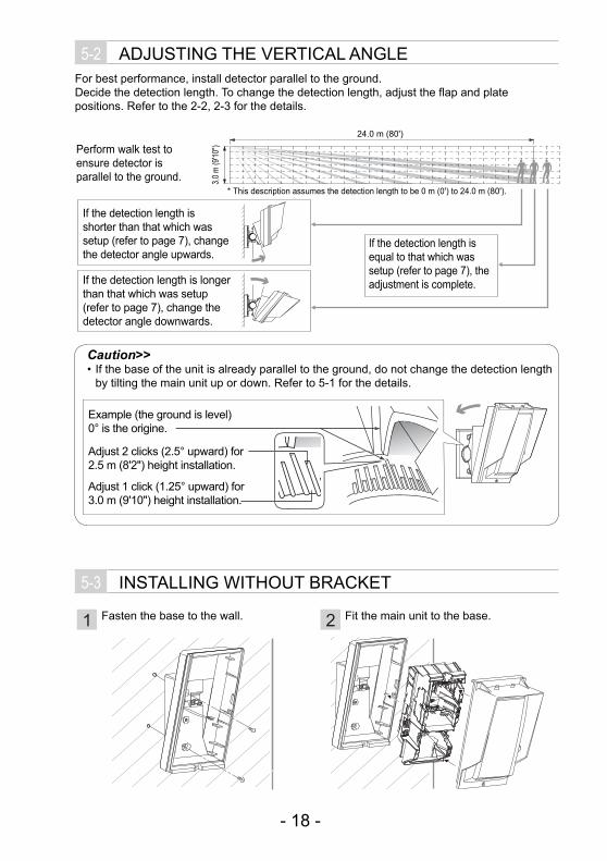
5-3 INSTALLING WITHOUT BRACKET
5-2 ADJUSTING THE VERTICAL ANGLEFor best performance, install detector parallel to the ground.Decide the detection length. To change the detection length, adjust the flap and plate positions. Refer to the 2-2, 2-3 for the details.
Caution>>If the base of the unit is already parallel to the ground, do not change the detection length by tilting the main unit up or down. Refer to 5-1 for the details.
•
1 Fasten the base to the wall. 2 Fit the main unit to the base.
3.0
m (9
'10")
24.0 m (80')
If the detection length is shorter than that which was setup (refer to page 7), change the detector angle upwards.
If the detection length is longer than that which was setup (refer to page 7), change the detector angle downwards.
If the detection length is equal to that which was setup (refer to page 7), the adjustment is complete.
* This description assumes the detection length to be 0 m (0') to 24.0 m (80').
Perform walk test to ensure detector is parallel to the ground.
Example (the ground is level) 0° is the origine.
Adjust 2 clicks (2.5° upward) for 2.5 m (8'2") height installation.
Adjust 1 click (1.25° upward) for 3.0 m (9'10") height installation.
- 18 -
HX-80NRAM_EN.indd 18HX-80NRAM_EN.indd 18 2010/08/20 9:18:512010/08/20 9:18:51
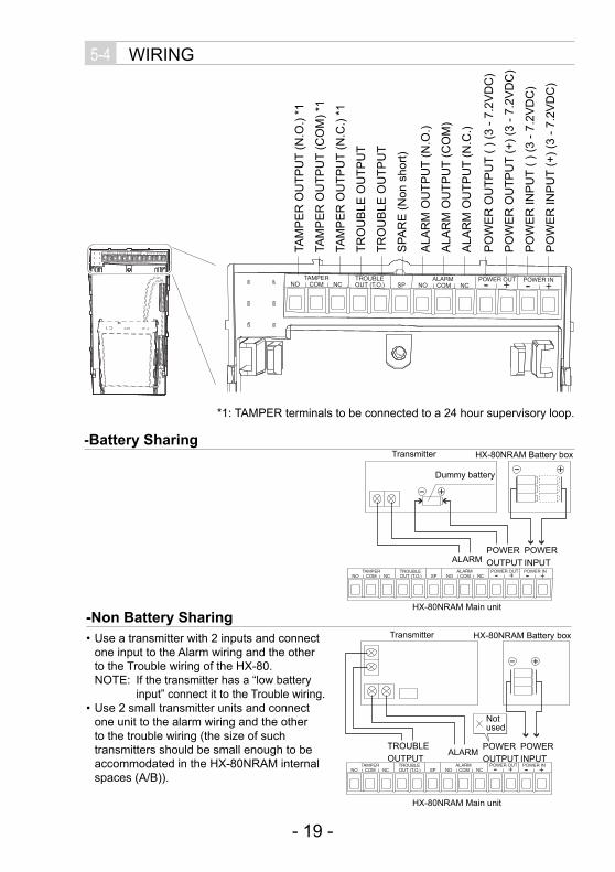
5-4 WIRING
NOTAMPER
COM NCTROUBLEOUT (T.O.) SP NO
ALARMCOM NC
POWER OUT- -+ +POWER IN
NOTAMPER
COM NCTROUBLENC NO SP NO
ALARMCOM NC
POWER OUT- -+ +POWER IN
*1: TAMPER terminals to be connected to a 24 hour supervisory loop.
-Battery Sharing
NOTAMPER
COM NCTROUBLEOUT (T.O.) SP NO
ALARMCOM NC
POWER OUT- -+ +POWER IN
-Non Battery SharingUse a transmitter with 2 inputs and connect one input to the Alarm wiring and the other to the Trouble wiring of the HX-80.NOTE: If the transmitter has a “low battery
input” connect it to the Trouble wiring.Use 2 small transmitter units and connect one unit to the alarm wiring and the other to the trouble wiring (the size of such transmitters should be small enough to be accommodated in the HX-80NRAM internal spaces (A/B)).
•
•
NOTAMPER
COM NCTROUBLEOUT (T.O.) SP NO
ALARMCOM NC
POWER OUT- -+ +POWER IN
TAM
PE
R O
UTP
UT
(N.O
.) *1
TAM
PE
R O
UTP
UT
(CO
M) *
1
TAM
PE
R O
UTP
UT
(N.C
.) *1
TRO
UB
LE O
UTP
UT
TRO
UB
LE O
UTP
UT
SPA
RE
(Non
sho
rt)
PO
WE
R O
UTP
UT
( ) (3
- 7.
2VD
C)
PO
WE
R O
UTP
UT
(+) (
3 - 7
.2V
DC
)
PO
WE
R IN
PU
T ( )
(3 -
7.2V
DC
)
PO
WE
R IN
PU
T (+
) (3
- 7.2
VD
C)
ALA
RM
OU
TPU
T (N
.O.)
ALA
RM
OU
TPU
T (C
OM
)
ALA
RM
OU
TPU
T (N
.C.)
Transmitter HX-80NRAM Battery box
ALARMPOWEROUTPUT
POWER INPUT
HX-80NRAM Main unit
Not used
Dummy battery
Transmitter HX-80NRAM Battery box
ALARMPOWEROUTPUT
POWER INPUT
TROUBLEOUTPUT
HX-80NRAM Main unit
- 19 -
HX-80NRAM_EN.indd 19HX-80NRAM_EN.indd 19 2010/08/20 9:18:512010/08/20 9:18:51

5-5 WALL TAMPER (OPTION)Commercial magnet switch may be mounted as a wall tamper.Magnet switch installation space is provided on the back of the main unit and the bracket.Maximum size of an applicable magnet switch: D 9 mm (0.35") × W 40 mm (1.57") × H 9 mm (0.35") Magnet switch is not included.
-WIRING DIAGRAM
NOTAMPER
COM NCTROUBLEOUT (T.O.) SP
Transmitter
Magnet switch
HX-80NRAM Main unit
BracketMain unit
Magnet switch (Wall side)installation position
Magnet switch (Bracket side) installation position
Wiring Hole
Magnet switch (Base side)installation position
Magnet switch (Wall side)installation position
- 20 -
HX-80NRAM_EN.indd 20HX-80NRAM_EN.indd 20 2010/08/20 9:18:512010/08/20 9:18:51

1 Install the magnet switch (wall side) to the wall. To determine the installation position, use the “Installation position template” provided on the inside cover of the product package.
2 Open the wiring knockout with suitable tool e.g. screwdriver.
3
2
1
34
2
3
4
65
1
4 Install bracket and main unit to the walls surface. 5 Connect the magnet switch wiring to the
tamper terminal of the main unit and the transmitter terminal.
-Installation
When not using the bracket
Fix
In
Wiring sponge padOut
When using the bracket
Fix
In
Wiring sponge pad
Out
In
In
Out
Tilt the bracket about 45° andpass through the wire.
Magnet switch
Install the other portion of the magnet switch to the back of the main unit or the bracket. Pull the wiring through the knockouts.
- 21 -
HX-80NRAM_EN.indd 21HX-80NRAM_EN.indd 21 2010/08/20 9:18:522010/08/20 9:18:52

6 WALK TEST
1 Set the DIP switch 1 (WALK TEST MODE) to “ON (TEST)”.
Note>>The switch is set to “ON (TEST)” by factory default.
•
2 Check that the detector detects an object in the intended detection area.The installation has been successful if the LED lights for two seconds after a person walks into the detection area.
Note>>For the walk test, move more than 1.0 m (3'3") away from the detector.
3 If the LED does not need to be turned on at all times, set the DIP switch 1 (WALK TEST MODE) to “OFF (NORM.)”.
7 SETTING
HISTDOFF
PIR 2(Do not touch)
PIR 1(Do not touch)
DIP switch1. WALK TEST MODE2. BATTERY SAVING TIMER3. IMMUNITY4. TROUBLE OUTPUT TYPE5. LOW BATTERY TERMINAL6. LED ON/ OFF7. PIR AND/OR
ANTI-MASKING SENSITIVITY
PIR SENSITIVITY
Detected Not detected
- 22 -
HX-80NRAM_EN.indd 22HX-80NRAM_EN.indd 22 2010/08/20 9:18:522010/08/20 9:18:52

-WALK TEST MODE DIP switch 1
TESTNORM.
POSITION FUNCTION
TEST (Factory default
LED will lights when someone detected regardless DIP-SW 6.
(Lights up irrespective of the LED ON/OFF (DIP-SW 6, refer to page 24) setting)
Alarm will be generated when someone detected regardless DIP-SW 2.
•
•
NORM. Normal operation. (Battery saving mode.)LED is off. (When LED ON/OFF is OFF.)
••
Caution>>After completing a walk test, always set the unit to NORM. position for operation. Using the unit in TEST mode will shorten the battery life.
-BATTERY SAVING TIMER DIP switch 2
5s120s
Even if there are continuous alarm events, the alarm is generated only once in the timer period to save the battery life.
POSITION FUNCTION
120s (Factory default)
120 sec.
5s 5 sec.
-IMMUNITY SWITCH DIP switch 3
IMMUNITYSTD
POSITION FUNCTION
STD(Factory default) IMMUNITY logic is not activated.
IMMUNITY IMMUNITY logic is activated. Use this under harsh environment (e.g. vegetation sway).
-TROUBLE OUTPUT TYPE DIP switch 4
N.O.N.C.
Select the contact point output form with the TROUBLE OUTPUT TERMINAL.
POSITION FUNCTION
N.C.(Factory default)
N.C. signal is output to the TROUBLE OUTPUT TERMINAL.
N.O. N.O. signal is output to the TROUBLE OUTPUT TERMINAL.
- 23 -
HX-80NRAM_EN.indd 23HX-80NRAM_EN.indd 23 2010/08/20 9:18:522010/08/20 9:18:52
Trouble signal output >>Trouble signal at regular intervals is output after trouble condition continues for a certain period.
• ANTI MASKING OUTPUT
When an object is placed close to the lens surface, for a period of more than 180 seconds, the IR Anti-Masking circuit will activate and generate a trouble signal.Anti-Masking output will be automatically reset within about one minute after a masking object is removed.
• LOW BATTERY OUTPUT (when the LOW BATTERY OUTPUT (DIP switch 5) is ON)
When the battery capacity becomes low, the unit automatically outputs fixed time transmission to call attention.When LOW BATTERY signal is output, Anti-Masking function will be canceled in order to extend the battery life.When LOW BATTERY signal is output, replace all the batteries with new ones.
WarningDo not use batteries of different capacities (i.e.: mixing new and used batteries) or of different manufacturers and/or types together. Not observing the above may result in an explosion, leakage of electrolyte, emission of toxic gases or other outcomes that may be harmful to people and property.
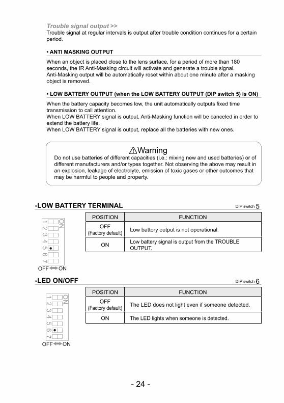
-LOW BATTERY TERMINAL DIP switch 5
ONOFF
POSITION FUNCTION
OFF (Factory default) Low battery output is not operational.
ON Low battery signal is output from the TROUBLE OUTPUT.
-LED ON/OFF DIP switch 6
ONOFF
POSITION FUNCTION
OFF (Factory default) The LED does not light even if someone detected.
ON The LED lights when someone is detected.
- 24 -
HX-80NRAM_EN.indd 24HX-80NRAM_EN.indd 24 2010/08/20 9:18:532010/08/20 9:18:53

-PIR AND/OR DIP switch 7
ORAND
POSITION FUNCTIONAND
(Factory default)An alarm is output when both PIR1 and PIR2 detect an object.
OR
An alarm is output when either PIR1 or PIR2 detects an object.Selecting “OR” mode makes detection range longer than “AND” mode. Walk test to readjust the detection range is required when “OR” is selected. Actual adjustment should be conducted by adjusting the bracket angle.
-PIR SENSITIVITY PIR SENSITIVITY SELECTOR
POSITION FUNCTIONHIGH High sensitivity
MIDDLE(Factory default) Middle sensitivity
LOW Low sensitivity
-ANTI-MASKING SENSITIVITYANTI-MASKING
SENSITIVITY SELECTOR
POSITION FUNCTIONHIGH High sensitivitySTD
(Factory default) Normal sensitivity
OFF Disabled
Caution>>After closing the cover, do not leave any objects closer than 1 meter from the unit.
HIGH
MIDDLE
LOW
HIGH
STD
OFF
Note>>“OR” mode is appropriate for the sites that require more detectability rather than false alarm tolerance such as lighting control and camera activation.
OR mode only
- 25 -
HX-80NRAM_EN.indd 25HX-80NRAM_EN.indd 25 2010/08/20 9:18:532010/08/20 9:18:53

8 LED INDICATION
DETECTOR CONDITION LED INDICATOR (RED ONLY)
Warm-upBlinks for approx. 60 sec.
AlarmLights for 2 sec.
Trouble output
Anti-Masking booting
(Anti-Masking start up) Blinks 2 times and goes off for 5 sec. and then repeats.
Masking detection
Blinks 3 times and goes off for 3 sec. and then repeats for 180 sec.
Low BatteryOutput
Blinks 4 times and goes off for 3 sec. and then repeats.
Note>>To distinguish a trouble output caused by low battery power, the low battery power LED display will light up when the cover is opened even if the LED ON/OFF (DIP-SW 6, refer to 7) is set to OFF.
Red LEDBlink Light OFF
- 26 -
HX-80NRAM_EN.indd 26HX-80NRAM_EN.indd 26 2010/08/20 9:18:532010/08/20 9:18:53

9 SPECIFICATIONS
9-1 SPECIFICATIONSModel HX-80NRAMDetection method Passive infraredPIR Coverage 24.0 m × 2.0 m (80' × 6'7") narrow / 20 zones PIR distance limit 6.5 m, 10.0 m, 13.0 m, 18.0 m (22', 33', 42', 59')Detectable speed 0.3 m/s – 1.5 m/s (1'/s – 4'11"/s)Sensitivity 2.0°C (3.6°F) at 0.6 m/sPower input 3 – 7.2 V DC Lithium Battery (CR123A × 3, CR2 × 3, 1/2AA × 3, 1/2AA × 6)Operating voltage 2.5 – 9 V DCCurrent draw 30 μ A (standby) / 4 mA (max.) at 3 V DCAlarm period 2.0 ±1 sec.Warm-up period Approx. 90 sec. (LED blinks)Alarm output Form C -Solid State Switch- 10 V DC 0.01 A max.Trouble output N.C./N.O. Selectable -Solid State Switch- 10 V DC 0.01 A max.Tamper output Form C. 28 V DC, 0.1 A max. changes when cover removed.
LED indicator Disable: During normal operation.
Enable: During WALK TEST or LED SW on.Red: Warm-up, Alarm, Trouble, Low battery
RF interference No alarm 10 V/mOperating temperature -20 – +60°C (-4 – +140°F)
Environment humidity 95% max.
Weatherproof IP55 Mounting WallMounting height 2.5 – 3.0 m (8'2" – 9'10") Bracket adjust angle Vertical: ±20° Horizontal: ±95°
Weight 780 g (27.5 oz.)
Accessories Bracket, Screw (4 × 20 mm) × 4, Velcro tape × 2, Alarm cable, Battery lead × 2, Dummy battery kit
*Specifications and designs are subject to change without prior notice.
- 27 -
HX-80NRAM_EN.indd 27HX-80NRAM_EN.indd 27 2010/08/20 9:18:542010/08/20 9:18:54

9-2 DIMENSIONS
93 (3.66")
197.
5 (7
.78"
)
286 (11.26") 205 (8.07") 93 (3.66")
197.
5 (7
.78"
)
The HX-80N series is only a part of a complete system, therefore we cannot accept complete responsibility for any damages or other consequences resulting from an intrusion.
Using bracket
Unit: mm (inch)
Without bracket
Unit: mm (inch)
As a rough indication of battery change timing, enter the battery type and the date it was first used.
Battery type Date (Year/Month)
OPTEX INCORPORATED (USA)TEL:+1-909-993-5770Tech:(800)966-7839 URL:http://www.optexamerica.com/
OPTEX KOREA CO., LTD. (KOREA)TEL:+82-2-719-5971URL:http://www.optexkorea.com/
OPTEX SECURITY Sp. z o. o. (POLAND)TEL:+48-22-598-06-55URL:http://www.optex.com.pl/
OPTEX (DONGGUAN) CO., LTD.SHENZHEN OFFICE (CHINA)TEL:+86-755-33302950URL:http://www.optexchina.com/
OPTEX CO., LTD. (JAPAN)(ISO 9001 Certified) (ISO 14001 Certified)5-8-12 Ogoto OtsuShiga 520-0101JAPANTEL:+81-77-579-8670FAX:+81-77-579-8190URL:http://www.optex.co.jp/e/
OPTEX (EUROPE) LTD. (UK)TEL:+44-1628-631000URL:http://www.optex-europe.com/
OPTEX SECURITY SAS (FRANCE)TEL:+33-437-55-50-50URL:http://www.optex-security.com/
- 28 -
HX-80NRAM_EN.indd 28HX-80NRAM_EN.indd 28 2010/08/20 9:18:542010/08/20 9:18:54