Embed Size (px)
Citation preview
Chapter 7
Hybrid Abrasive Water Jet and Milling Process
Dr. J. Ramkumar1 and Gopal Gupta2
1Professor and 2Research Student
Department of Mechanical Engineering
Micromanufacturing Lab, I.I.T. Kanpur
Micromanufacturing Lab, I.I.T. Kanpur

Index1. Introduction
2. Types of Milling processa) Conventional Milling (Up milling)
b) Climb Milling ( Down milling )
3. Type of chips form during milling process
4. Deep pocket Conventional Millinga) Best machining approach in Deep pocket Milling
b) Strategies for Deep pocket milling
c) Heat distribution of special alloy in conventional milling
5. Abrasive Water Jet Millinga) Abrasive Water Jet Milling With Masks
b) Mask-Less Abrasive Waterjet Milling
6. Advantage and disadvantage of Mask and Mask-less AWJM
7. Geometrical parameter of AWJM
8. Process parameter of AWJM
Micromanufacturing Lab, I.I.T. Kanpur

9. Abrasive Waterjet milling strategy
10. Influence of Impingement Angle
a) Forward Milling
b) Backward milling
11. Effect of Impact angle, Abrasive loading & jet water pressure
12. Hybrid approach: AWJM roughing & Conventional milling
finishing
13. Hybrid Machine Cycle
a) Abrasive Waterjet Milling Cycle
b) Conventional Milling Cycle
14. Operation of Hybrid milling
15. Conclusion
16. Reference
Micromanufacturing Lab, I.I.T. Kanpur

1.Introduction • When specially shaped features must be obtained on hard-to-
machine materials, well-established and innovative technologies
may cooperate for generating better results in terms of performance,
quality and resource saving.
• Conventional Milling:-
• Milling is the machining operation in which a workpiece is fed past
a rotating cylindrical tool with multiple cutting edge and This
milling is the multipoint cutting process.
• The material is remove in the form of small chips, The chip
thickness is minimum at start of cut and maximum at the end.
• There is less friction involved and consequently less heat generate
on the contact surface of cutter and workpiece .
Micromanufacturing Lab, I.I.T. Kanpur

• AWJM
1) Abrasive Waterjet Milling process is a water-driven grinding
process. A narrow, high-pressure jet of water carries particles
of garnet abrasive at speeds ranging from 1,000 to 2,400 feet
per second. This garnet does the cutting of Workpiece.
2) Abrasive Waterjet machining often finds work cutting hard
steels, Titanium(Ti) alloys, aerospace alloys, and other
materials that are difficult to machine through conventional
mechanical cutting process such as Grinding, Drilling,
Boring etc.
3) There is “No heat affected zone’’ form during AWJM
process and this process can able to cut Workpiece up to 200
mm thickness.
Micromanufacturing Lab, I.I.T. Kanpur

2.Types of Milling process
a) Up Milling ( Conventional Milling) b) Down Milling ( Climb Milling )
1) In Up Milling cutter rotate against
the of Feed
2) Chip thickness is minimum at the
start of cut and maximum at the end
of cut.
3) In Up milling tool wear is more
because tool moves against the feed
4) Due to upward force by tool, high
strength fixture required to hold the
workpiece.
1) In Down Milling cutter rotate in the
direction of Feed
2) Chip thickness is maximum at the start
of cut and minimum at end of cut
3) In Down milling Tool wear is less
because tool moves toward the feed
direction
4)\ Down word force act on workpiece
hence Normal Fixture required to
hold the workpiece.

3. Type of Chips form in Milling
❖ Continuous Chip ❖ Segmented Chip
1) Continuous chip occur during
machining of ductile material.
2) High rake angle of tool, High
cutting speed, Small depth of cut
and minimum friction between
tool and workpiece are responsible
for Continuous chip formation.
3) Crater wear occur due continuous
chip
4) Better surface finish occur due to
continuous chip formation
1) Segmented chip occur during
machining of Brittle & Hard material
2) Low rake angle of tool, Low cutting
speed, high depth of cut and maximum
friction between tool and workpiece
are responsible for segmented chip
formation.
3) Tearing of tool take place due to
Segmented chip formation
4) Poor surface finish & excessive wear
occur due to segmented chip formation
Fig1- segmented Chip evaluation m/c process [1]Fig1.a-contineous Chip evaluation [1]

4. Deep Pocket conventional Milling• Deep pocket cM is a typically very demanding operation because it helps to
remove the large stock of material with high surface finish quality.
• However, large overhang of the tools, up to four times the cutter diameter
(or more), are required for reaching the cavities. This fact generates high
tool deflection leading to geometrical deviations, reduced cutter stability
with increased risks of tool breakage.
• To avoid these problems, the use of the largest possible tool size and the
shortest possible overhang must be prescribed to achieve the best
diameter/length ratio and the most rigid configuration.
• Deep pockets are very common features, e.g., in aircraft components made
of Ti-alloy
Fig.2- Step Deep Pocket milling by conventional milling [2]
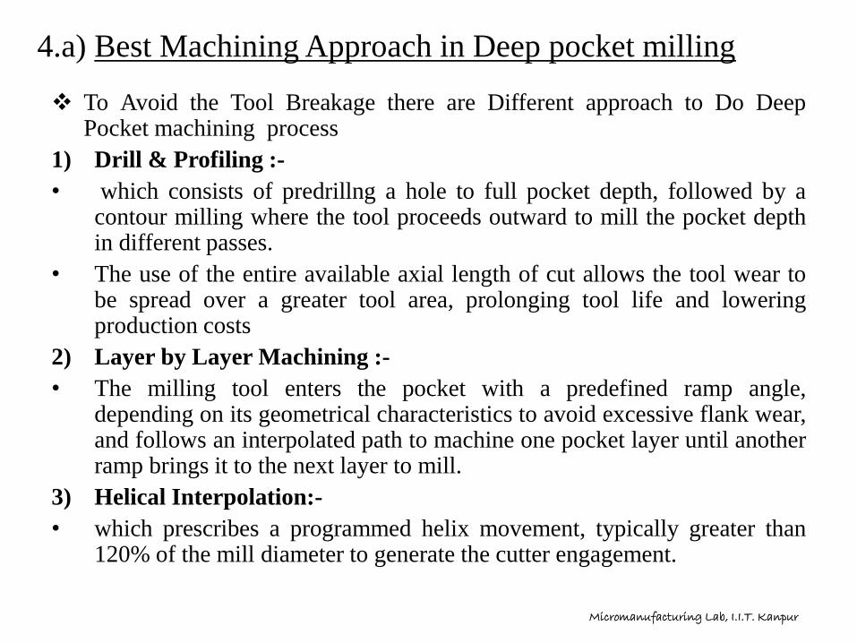
4.a) Best Machining Approach in Deep pocket milling
❖ To Avoid the Tool Breakage there are Different approach to Do DeepPocket machining process
1) Drill & Profiling :-
• which consists of predrillng a hole to full pocket depth, followed by acontour milling where the tool proceeds outward to mill the pocket depthin different passes.
• The use of the entire available axial length of cut allows the tool wear tobe spread over a greater tool area, prolonging tool life and loweringproduction costs
2) Layer by Layer Machining :-
• The milling tool enters the pocket with a predefined ramp angle,depending on its geometrical characteristics to avoid excessive flank wear,and follows an interpolated path to machine one pocket layer until anotherramp brings it to the next layer to mill.
3) Helical Interpolation:-
• which prescribes a programmed helix movement, typically greater than120% of the mill diameter to generate the cutter engagement.
Micromanufacturing Lab, I.I.T. Kanpur

4.b) Strategies for Deep pocket Milling
❖ Trichoidal Tool Path :-
• low radial depth of cut and high axial depth of cut that can be used to
ensure extremely fast material removal and high volumes with reduced
tool stresses, especially on difficult-to-cut materials.
• Although they typically require machining centers with high dynamics
and complex programming, Trichoidal and spiral strategies often do
better than traditional contour- and direction-parallel tool paths.
Fig3.- Trichoidal Path Fallow by Milling
Cutter [3]
Advantage of Trichoidal Path
1) Decrease Cutting Forces
2) Reduce Heat & Improve Tool
Life
3) Greater Machining Accuracy
4) Faster Cycle time and one tool
for multiple slots
Micromanufacturing Lab, I.I.T. Kanpur

4. c) Heat distribution profile during Conventional Milling of special alloy
Fig4.- Heat Transmission during the machining of steel CK-45 & Ti-64 [2]
Micromanufacturing Lab, I.I.T. Kanpur

5.Abrasive Waterjet Milling• Water is pressurized up to 600 MPa and forced to pass through a tiny
orifice to get a high velocity jet.
• Abrasive is added downstream, in the mixing chamber, and the water
stream accelerates it along the focusing tube.
• The three-phase jet (i.e., water, abrasive, and air) impacts the target
material and cuts it by abrasion and erosion.
• AWJM material removal rate approximately proportional to the jet-
workpiece material interaction time.
Micromanufacturing Lab, I.I.T. Kanpur

Types of Abrasive Waterjet Milling
• AWJM in different aspects such as geometric milling strategy, process
parameters optimization, and AWJ trajectory simulation.
1) AWJ milling with masks:-
• A mask made of hard metal allows using a spread jet and
preserving the pocket sharp edges.
2) Mask-less AWJ milling:-
• High milling depth is achieved exploiting a coherent jet.
Micromanufacturing Lab, I.I.T. Kanpur

5.a) Abrasive Waterjet milling with Masks
• The most used strategy exploits the protective action of custom-shaped
masks, since it achieves better geometric characteristics.
• The mask has an aperture that coincides with the zone to be milled, This
way the jet erodes only this portion.
• A hard metal mask is used indeed for overcoming the edge-rounding
problem: it allows separating the areas to be machined from the ones to be
preserved, thus resulting in sharp edges at the pocket top.
• The application of a mask over the workpiece allows avoiding the negative
effects of the jet motion when changing feed direction that induce high
acceleration forces and cause under- or over erosion on the part.
Fig5. AWJM with Mask coated Workpiece [4] Micromanufacturing Lab, I.I.T. Kanpur

Different Machining Method
1) Radial AWJ milling with Mask:-
• The nozzle moves radially with respect to the table rotational axis.
2) Internal Cylindrical AWJ milling :-
• The AWJ cutting head is placed radially and moves along the axial
direction of the rotating table, where the workpiece is fixture.
Fig6:- Radial AWJM mask
milling[5]
Fig7:- Internal Cylindrical AWJM mask milling [5]
Micromanufacturing Lab, I.I.T. Kanpur

Processing Steps of AWJM with Masks
Fig8. Mask Placed on Workpiece in Abrasive Waterjet milling Process [6]
Micromanufacturing Lab, I.I.T. Kanpur

5.b) Mask-less Abrasive Waterjet Milling
• Mask-less AWJM exploits the coherent jet full power at low s.o.d. (nearly 3
mm from the workpiece upper surface), Working so close to the workpiece
allows reducing the undesired edge roundness effect at the top surface.
• The focused erosive action allows a more effective material removal, thus
reducing the operation time and allowing digging deep on workpiece.
Fig9. Mask less AWJM [7]
Micromanufacturing Lab, I.I.T. Kanpur

6. Advantage and Disadvantage Mask & Mask less AWJM
AWJM with Mask
Advantage:-
1) Exact size and sharp edge
complicated shape
machining possible by
using Mask
2) Easy to operate Machine
once Mask Prepared
Disadvantage
1) High Cost of Mask and
Mask holding fixture
2) Complicated design setup
Mask Less AWJM
Advantage:-
1) High cost Mask & Mask holding fixture not required in this process
2) less operation time due simple design setup
Disadvantage :-
1) The presence of macroscopic jet footprints on the pocket bottom and the difficult management of the exiting jet.
2) The jet reflected by the eroded material is still highly energetic and therefore still able to damage the pocket walls when exiting the cavity
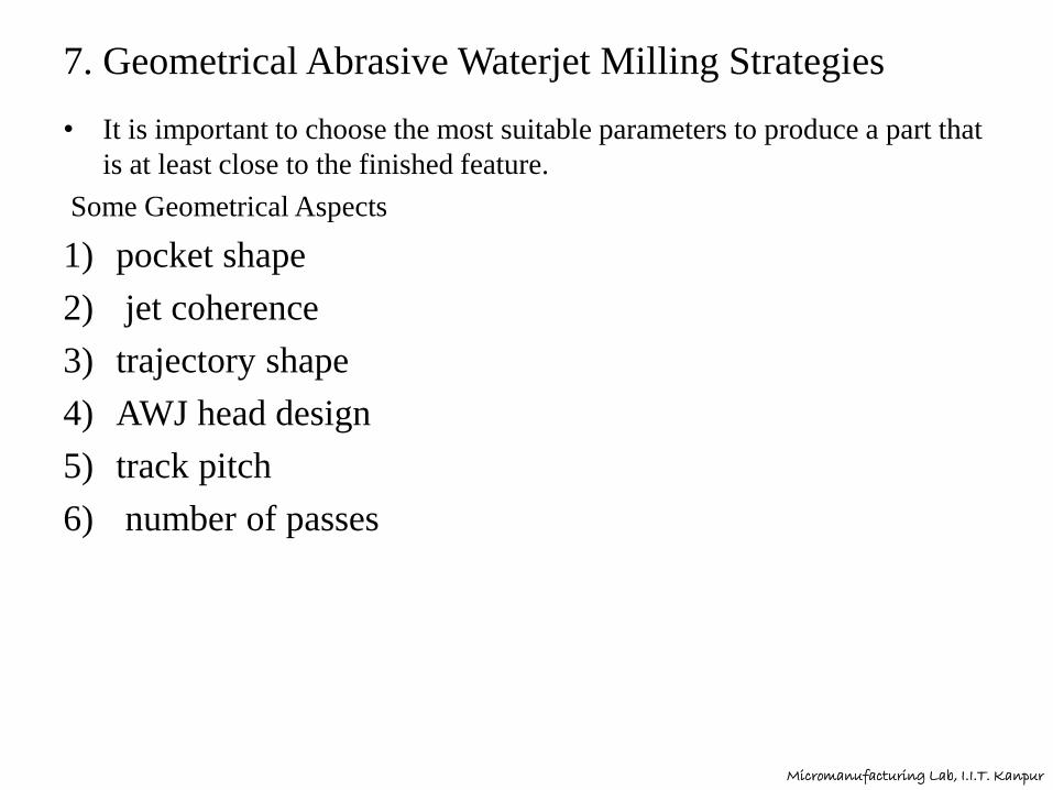
7. Geometrical Abrasive Waterjet Milling Strategies
• It is important to choose the most suitable parameters to produce a part that
is at least close to the finished feature.
Some Geometrical Aspects
1) pocket shape
2) jet coherence
3) trajectory shape
4) AWJ head design
5) track pitch
6) number of passes
Micromanufacturing Lab, I.I.T. Kanpur

8. Process Parameter of AWJM [8]
Process Parameter Symbol ( Unit) Parameter Value
Orifice diameter do [mm] 0.356
Abrasive Mesh Size # mesh 60/80/100/150
Abrasive Mass Flow Rate Mab
[ g/min]78/102/144/246/282/386
Water Pressure Pw 172/207
Stand Of Distance ( S.o.d ) [mm] 12/13/25/28/51
Feed Rate Vf
[mm/ min]76.2/152.4/228.6
Overlapping Pitch mm 0.254
Number Of Passes 1/2/3/4
Micromanufacturing Lab, I.I.T. Kanpur

9. AWJ milling strategies
• Both the achieved waviness and surface roughness must be investigated
when assessing the quality of the AWJ milling process in terms of produced
surface
• The focus is always to obtain pockets with a shape that is as close as
possible to the designed one. To achieve a constant pocket depth, a constant
surface exposure time to the jet is required, These aspects are extensively
analyzed together with the effects of three different milling strategies
1) Mild jet milling:- The abrasive mass flow rate reduction keeps the jet
energy low.
2) Milling with high feed rate
3) Discredited milling:-
• It is used for hard materials and consists in adding a certain amount of
abrasive to a stationary jet (feed rate =0)
• The jet plain is turned on over the workpiece, then the abrasive is fed
to the cutting head to create a cavity, Then the jet is turned off.
• After moving the machining head and turning the jet on again, another
cavity is created and so on. The final pattern creates a single larger
cavity. Micromanufacturing Lab, I.I.T. Kanpur

• Various milling paths can be used in the case of mild jet and fast traverse
jet.
• The best results are obtained with a fast jet, where the influence of the
strategies on the peak to valley distance on the pocket bottom is minimal
Micromanufacturing Lab, I.I.T. Kanpur

Innovative Abrasive water jet Milling Path cycle
Fig10.- Innovative Milling Jet path cycle [9]
Micromanufacturing Lab, I.I.T. Kanpur

10. Influence of Jet Impingement angle
a) Forward Milling
High Jet Angle AWJM Low Jet Angle AWJM
Fig11- Girt Embedment in Forward Milling with (a) High jet Angle
impingement, (b) Low jet Angle Impingement [10]
(a) (b)
Micromanufacturing Lab, I.I.T. Kanpur
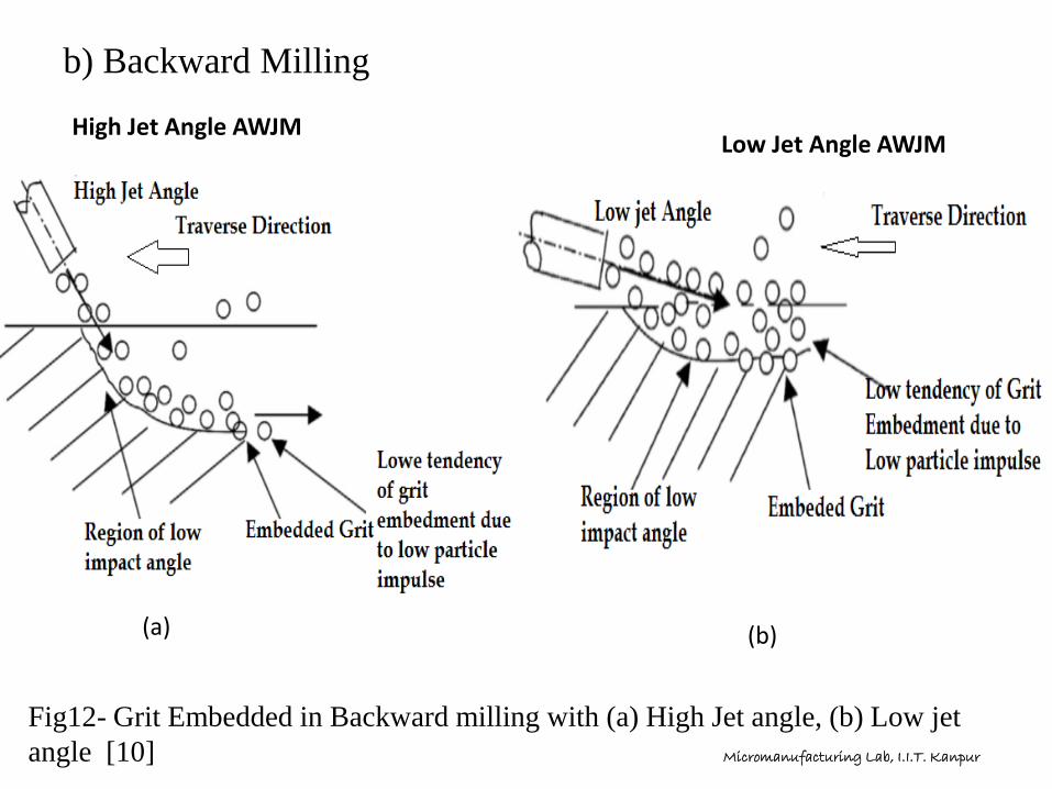
b) Backward Milling
High Jet Angle AWJMLow Jet Angle AWJM
Fig12- Grit Embedded in Backward milling with (a) High Jet angle, (b) Low jet
angle [10]
(a) (b)
Micromanufacturing Lab, I.I.T. Kanpur

11. Effect of impact angle, Abrasive & Water Pressure
• Waviness and roughness are directly proportional with the impingement
angle. Indeed, as it decreases also the two output variables decrease.
• If water pressure increases and abrasive mesh decreases, the material
removal rate and the waviness increase, On the other hand, pressure and
abrasive mesh cause opposite effects on the material removal rate and on
the waviness.
• Abrasive particles embedment can cause harmful damages when
components are put in service, such as fatigue life reduction or coating
delamination of workpiece surface. Therefore, it is important to understand
the factors that contribute to this phenomenon. At low jet feed rate, the
milling strategy has an impact in the grit embedment.
• Forward Milling is used for Surface Morphology and Backward Milling is
used for to groove the surface.
• The obtained surface roughness is in the range of 1.2-1.8 μm, the waviness
is 5-170 μm, and finally the MRR ranges between 12 and 20 mm3/s
Micromanufacturing Lab, I.I.T. Kanpur
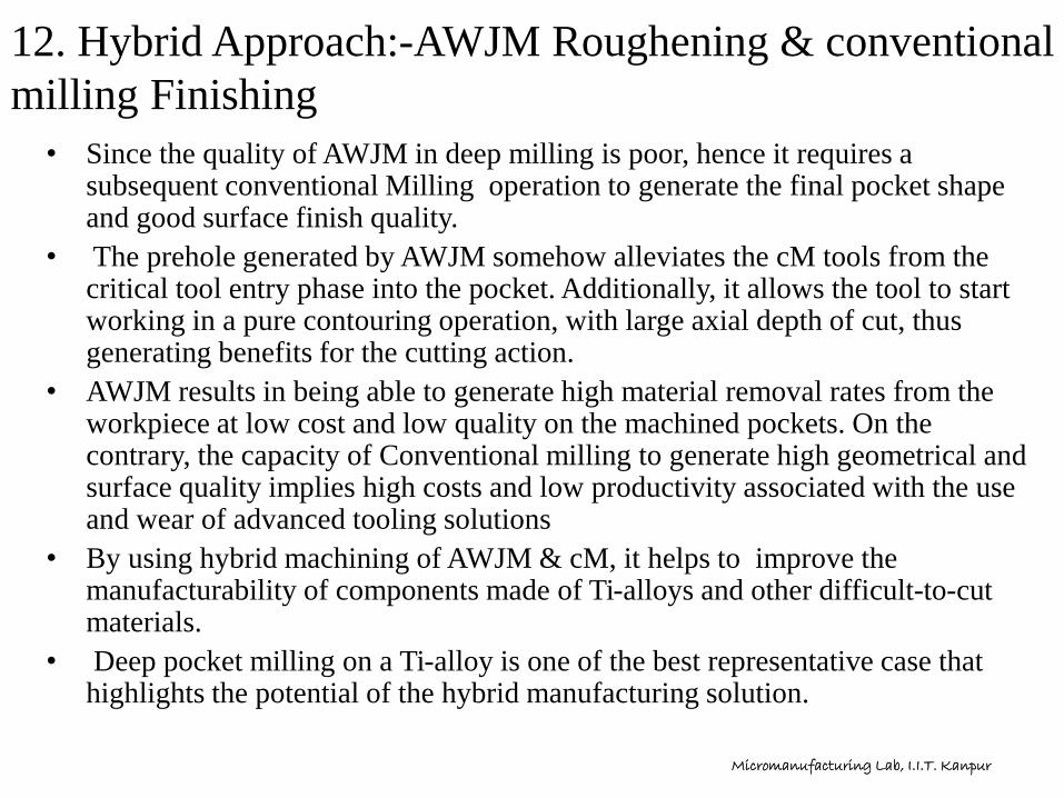
12. Hybrid Approach:-AWJM Roughening & conventional
milling Finishing
• Since the quality of AWJM in deep milling is poor, hence it requires a subsequent conventional Milling operation to generate the final pocket shape and good surface finish quality.
• The prehole generated by AWJM somehow alleviates the cM tools from the critical tool entry phase into the pocket. Additionally, it allows the tool to start working in a pure contouring operation, with large axial depth of cut, thus generating benefits for the cutting action.
• AWJM results in being able to generate high material removal rates from the workpiece at low cost and low quality on the machined pockets. On the contrary, the capacity of Conventional milling to generate high geometrical and surface quality implies high costs and low productivity associated with the use and wear of advanced tooling solutions
• By using hybrid machining of AWJM & cM, it helps to improve the manufacturability of components made of Ti-alloys and other difficult-to-cut materials.
• Deep pocket milling on a Ti-alloy is one of the best representative case that highlights the potential of the hybrid manufacturing solution.
Micromanufacturing Lab, I.I.T. Kanpur

13. Hybrid Machine cycle
a) Abrasive Waterjet Cycle :-
• For remove more material from the surface of Workpiece or more
Surface roughening .
b) Conventional Milling cycle :-
• After AWJM process finishing operation is done by conventional
milling process
AWJM Cycle
Surface Roughening of
Workpiece by using
AWJ Milling
Conventional Milling
Cycle
Surface Finishing of
workpiece by using
Conventional Milling
Step 1 Step 2
Micromanufacturing Lab, I.I.T. Kanpur

13.a) AWJM cycle
Fig13- Jet deflection during milling operation[11]
Fig – Spiral shape trajectory for AWJM
Fig14- Workpiece after AWJM process[11]
Micromanufacturing Lab, I.I.T. Kanpur

• Coming back to the AWJM operation, particular attention has to be paid not
only to the process parameters, i.e., water pressure, abrasive size, mass
flow rate, and cutting head feedrate, but also to the geometrical ones.
• Waterjet trajectory and distance between each parallel track (pitch) are two
geometrical characteristics that must be carefully selected due to their
influence on the final product.
• Single AWJ pass exploiting the jet erosion power is adopted in the
following for creating the target depth, by selecting a suitable combination
of process parameters and trajectory design.
Fig15- Visual comparison between pockets machined with different strategies [11]
(a) 7 revolutions, resulting in swallow-tail shape
(b) 6 revolutions with tuned process parameters, resulting in a more regularly
roughed pocket.
(c) 6 revolutions with higher Vf and lower mab resulting in a central thin wall
Micromanufacturing Lab, I.I.T. Kanpur

13.b) Conventional Milling Cycle
• The pocket roughed through AWJM must be finally machined using
conventional Milling.
• The first aspect to consider regards the optimal pocket shape. The pocket
that shows the best surface regularity together with the highest depth
allowing the cM tool to work in a pure contouring fashion must be
preferred.
• The efficiency of the AWJM roughing operation is investigated in terms of
total production time saving.
• The analysis is conducted comparing the machining time of the cM
operation starting from the bulk material and the one starting from the
AWJM roughed pocket.
• The final target is to find the break-even condition, in terms of total
machining time, between the workpiece entirely machined with cM and the
one machined by adopting the hybrid strategy AWJM + cM.
Micromanufacturing Lab, I.I.T. Kanpur

Step 1- Roughening of
Workpiece by
AWJM
Step 2- Finishing Slot
by Conventional milling
Final Finish Workpiece after Hybrid milling[ AWJM + c M ]
Fig16. Hybrid Milling Process [12] Micromanufacturing Lab, I.I.T. Kanpur
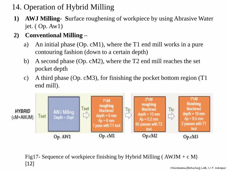
14. Operation of Hybrid Milling
1) AWJ Milling- Surface roughening of workpiece by using Abrasive Water
jet. ( Op. Aw1)
2) Conventional Milling –
a) An initial phase (Op. cM1), where the T1 end mill works in a pure
contouring fashion (down to a certain depth)
b) A second phase (Op. cM2), where the T2 end mill reaches the set
pocket depth
c) A third phase (Op. cM3), for finishing the pocket bottom region (T1
end mill).
Fig17- Sequence of workpiece finishing by Hybrid Milling ( AWJM + c M) [12]
Micromanufacturing Lab, I.I.T. Kanpur
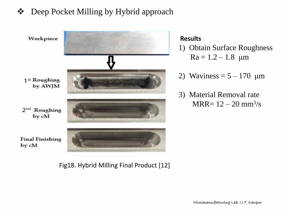
❖ Deep Pocket Milling by Hybrid approach
Results
1) Obtain Surface Roughness
Ra = 1.2 – 1.8 μm
2) Waviness = 5 – 170 μm
3) Material Removal rate
MRR= 12 – 20 mm3/s
Fig18. Hybrid Milling Final Product [12]
Micromanufacturing Lab, I.I.T. Kanpur

Conclusion• Hybrid manufacturing can help to solve advanced manufacturing
challenges such as the deep pocket manufacturing in difficult-to-cut
materials like titanium, Inconel and other alloys.
• The conjunct use of Abrasive Waterjet Milling (AWJM) and cM can be
integrated in a single hybrid approach to tackle the limited machinability of
these materials with standard cutting technologies by increasing the overall
process capability.
• It is demonstrated that this complementary hybrid approach, applied to
traditional cM strategies, is more effective in time saving as the pocket
depth increases (up to 13% in a 25 mm deep pocket compared to the 19
mm deep one)
• Final finish obtain by hybrid milling is 1 to 2 μm , less chance of braking
tool because roughing of workpiece done by contact less Abrasive jet , less
machining time and high process capabilities are the advantage of hybrid
milling approach.
• Eventually, the overall hybrid process chain layout must be designed in
order to evaluate all the other aspects such as the workpiece loading and
unloading time on the machines.
Micromanufacturing Lab, I.I.T. Kanpur
Reference [1] Titanium machining guide, by Kennametal.
,https://www.kennametal.com/content/dam/
kennametal/kennametal/common/Resources/Catalogs-
Literature/Metalworking/Titanium_ material_machining_guide_Aerospace.pdf.
(2017) (accessed 17th November 2017).
[2] M. Kuttolamadom, J. Jones, L. Mears, T. Kurfess, A. Choragudi. Investigation of the
Machining of Titanium Components for Lightweight Vehicles, 2010, No. 2010-01-
0022 SAE Technical Paper
[3] New Test Results in Cycloid-Forming Trochoidal Milling István Szalóki, SándorCsuka, Sándor Sipos
[4] K.M.C. O ¨jmertz, M. Jonasson, G. Holmqvist, Analysis of surfaces produced by
abrasive waterjet milling techniques, Bhr Group Conference series publication, vol.
21, Mechanical Engineering Publications Limited, 1996, pp. 753768.
[5] M. Hashish. Waterjet pocket milling of titanium aluminide. In Proceedings of the
19th International Conference on Water Jetting, P. Longman, ed., BHR Group,
Cranfield, UK, 2008, pp. 365-376
Micromanufacturing Lab, I.I.T. Kanpur

[6] P. Miles, A. Henning. Deep pocket milling with abrasive waterjets. In
Proceedings of 23rd International Conference on Water Jetting 2016,
Seattle, WA (pp. US Waterjet Conference, Berkeley, CA, 2016, pp. 113-
126.
[7] T. Nguyen, J. Wang, N.M. Kwok, H. Li, Q.P. Ha. Predictive models for the
geometrical characteristics of channels milled by abrasive waterjet. In
Automation Science and Engineering (CASE), 2015 IEEE International
Conference on, 2015, pp. 14591464. IEEE
[8] M. Hashish. Milling with abrasive waterjets: a preliminary investigation.
(1987) In Proceedings of 4th US Waterjet Conference, Berkeley, CA (pp. 1-
10).
[9] S. Anwar, D.A. Axinte, A.A. Becker, Finite element modelling of
overlapping abrasive waterjet milled footprints, Wear 303 (1) (2013)
426436.
[10] P.H. Shipway, G. Fowler, I.R. Pashby, Characteristics of the surface of a
titanium alloy following milling with abrasive waterjets, Wear 258 (1)
(2005) 123132.
Micromanufacturing Lab, I.I.T. Kanpur

[11] P.H. Shipway, G. Fowler, I.R. Pashby, Characteristics of the surface of a
titanium alloy following milling with abrasive waterjets, Wear 258 (1)
(2005) 123132.
[12] Hybrid Abrasive Waterjet and Milling Process
Francesco Vigano `, Paolo Parenti and Massimiliano Annoni Politecnico di
Milano, Milano, Italy
Micromanufacturing Lab, I.I.T. Kanpur

Thank You
Micromanufacturing Lab, I.I.T. Kanpur