Embed Size (px)
Citation preview
Electronics and Communications in Japan, Part 1, Vol. 71, No. 4 , 1988 Translated from Denshi Tsushin Gakkai Ronbunshi, V o l . 69-B, No. 7, July 1986, pp. 676-685
Hybrid ARQ System Employing Soft Decoding Algorithm
Hideo Kobayashi, Member
Research and Development Laboratories, Kokusai Denshin Denwa Co., Ltd., Japan 153
SUMMARY
It is known that by applying a soft de- coding algorithm to the error-detecting code in the ARQ system, a hybrid ARQ system can be realized in which error detection and cor- rection are possible. This paper discusses the application of the soft decoding algor- ithm to the ARQ system, where the multi- valued digital modulation is employed. A scheme for a practical system is proposed, including the detection of channel measure- ment information in the multivalued digital modulation system and estimation of error patterns. By the proposed method, the hybrid ARQ system can easily be realized by adding some peripheral circuits to the conventional ARQ receiver. Theoretical study is made on the number of error patterns that can be esti- mated for a long block length as well as the probability of miss and the probability of retransmission request. The proposed scheme was applied experimentally to the ARQ system employing SG VIII V.29 modem based on CCITT recommendation, and the usefulness of the proposed scheme was verified by experiment.
1. Introduction
In most of the present data communica- tion systems in which a high quality is re- quired, the ARQ system is employed. This is because the hardware implementation is easy, and the reliability is much higher than the forward error-correcting system (FEC). One of the problems in the ARQ system is that once an error of even a bit is detected in a block, the whole block must be retransmitted, which is not efficient.
To cope with this problem, the hybrid ARQ system is proposed with the features of both ARQ and FEC systems. system, all errors that can be corrected are corrected on the receiver side, and only the errors that cannot be corrected are detected and retransmitted. Two schemes are consid- ered for the hybrid ARQ system: 1) employ
In the proposed
70
the code for which the error-detection and error-correction are both possible [ l ] ; and 2) use the soft decoding algorithm in the error-detecting code [ 2 ] .
Sundberg et al. studied the latter method, which is considered highly practical for the following reasons. The error-de- tecting code used in the conventional ARQ system can be applied directly, thereby im- proving the coding efficiency. error-correcting ability can be realized without degrading the ability of the error- detecting code. Sundberg et al., however, is only theoreti- cal, assuming the binary transmission.
Then a new
The discussion made by
Consequently, the method cannot di- rectly be applied to the ARQ system employing a highly efficient digital modulation scheme, such as the multiphase PSK and multivalued QAM, which are applied widely in the present digital communication systems. Neither has there been a discussion on the hardware im- plementation of the idea.
It should also be noted that the theo- retical analysis by Sundberg et al. is ap- plicable only to the error-detecting code with short block length. The performance cannot accurately be estimated for the block length of several hundreds bit, as is used in the actual ARQ system, and the estimation of the improvement of the transmission effi- ciency is insufficient.
With the foregoing as background, this paper discusses first the ARQ system in which the soft decoding algorithm [ 8 ] proposed by the authors can be applied to the ARQ system based on the multivalued digital modulation- demodulation. It is shown also that the hybrid ARQ system can be realized by adding only some peripheral circuits to the con- ventional ARQ receiver. Then a theoretical discussion is made on the performance of the error-detecting code with a large block length, as in the actual ARQ system, using the soft decoding algorithm. Considering the
1SSN8756-6621/88/0004-0070$7.50/0 0 1988 Scripta Technica, Inc.

el CIIANNEL
ERROR
I I
I I I I I I I I I I f I
4 I
I ANALOG I
I I
I
0 1 : Selected when an error q' is not detected I[' SW 02 : Selected when an error
is detected
Fig. 1. Block diagram of ARQ system using soft decoding algorithm.
case where the V.29 modem [ 4 ] of CCITT recom- mendation is used as the modem of the ARQ system, the experimental system was con- structed. The improvement of the transmis- sion efficiency of the proposed hybrid ARQ system is examined by experiment.
2 . Soft Decoding Algorithm
This section shows that the hybrid ARQ system is realized by applying the soft de- coding algorithm to the decoding in the ARQ system. digital modulation system, the channel mea- surement information detection and the esti- mation of error patterns are described, which are needed in the implementation of the pro- posed scheme.
Assuming the case of the multivalued
2.1 System structure
Figure 1 is the block diagram of the proposed communication system used to describe the proposed scheme. The encoder produces the error-detecting code by adding redundant (n - k) bits to the k information bits. The transmitted code sequence composed of n-bits goes to the modulator, and the modulated sig- nal S ( t ) is transmitted to the channel.
Let the k-bit information part be rep- resented by the polynomial M ( x ) . Let the generator polynomial for the redundant bits be G ( x ) , and the n-bit transmitted code sequence be F(x). Then the following rela- tion applies to M ( x ) , G(x) and F(x):
F ( x ) = M ( z ) x n - k - R ( z )
= G ( 4 Q(4 (1)
p-k where & ( x ) is the quotient when M(x) - is divided by G ( x ) ; R(x) is the remainder.
On the receiving side, the conventional hard decision as well as the soft decoding are performed on the signal r ( t ) which con- tains the channel noise. The channel mea- surement information (a, B ) for each element* is detected; a is the information indicating the easiness of producing an error in the re- ceived signal, and B is the information in- dicating from which signal region the error is derived if the received element is in error. The details of the detection of the channel measurement information ( a , B ) is described in Sect. 2.2.
Forthe result oftheharddecision F'(z), the existence of the error is checked, using the algebraic decoding; F'(x) contains the error E(x) due to the channel noise, and is represented as follows:
F' (x ) = F (x) f E (x ) (2)
n-1. , where E(x) = e
e is 1 when the demodulated bit is in error,
and is 0 otherwise. The error detection by the algebraic decoding is made by examining whether or not G(x) divides F ' ( x ) in Eq. ( 2 ) . When G(x) divides F'(x), one can consider that E ( x ) = 0 as is seen from Eqs. (1) and (2), and it is determined that there is no error. decoder and M(x) is sent to the receiver. When an error is detected in a block, the following manipulation is made to correct the error.
+ e x + e x2 + s.9 + e 0 1 2 n- 1 x
i
The zedundant bit is removed in the
For the block for which an error i s de- tected, the channel measurement information a for each element is compared, and several elements with the highest possibilities of error are detected. Then using the channel measurement B for the detected elements and
*By element is meant the modulation element. In the m-valued transmission, in general, log m bits can be transmitted by a modulation element.
2
71

the result of the hard decision, several pos- sible patterns for the error Ei(z) (i - 1
- z) are estimated. The details of the error pattern estimation are described in Sect. 2 . 3 .
Fofming the sum of the estimated error pattern Ei(x) and F ' ( x )
the existence of an error is checked by the algebraic decoding. Assume that the error is not detected when the jth estimated error pattern E . ( x ) is used, that one can consider
that E ( x ) = 8.(x) as is seen from Eqs. (2) and ( 3 ) , and the error can be corrected. If the error is detected for all estimated error patterns, one should conclude that the same pattern does not exist in the estimated error patterns as the error E ( x ) produced on the channel. The error correction then is a failure.
J
3
However, in such a case, the error is detected. Consequently, the decoding algor- ithm discussed earlier is applied. Thus, a hybrid ARQ system with both error-detecting and error-correcting abilities is realized. This idea can be realized by adding the part surrounded by the dashed line in Fig. 1 to the conventional ARQ receiver, and are the channel-measurement information-detecting circuit and the error-pattern estimating circuit. In the following, the case of mul- tivalued digital modulation is assumed, and the channel-measurement information detection and the error-pattern estimation are de- scribed, which are needed in the implementa- tion of the proposed algorithm.
2.2 Channel-measurement information detect ion
This section describes the channel- measurement information detection, which is needed to indicate the receiving state for each element. Kobayashi et al. proposed the channel-measurement information detection for the multiphase PSK system [ 3 ] . In the chan- nel-measurement information (a, 8 ) defined in that scheme, a indicates the easiness of producing an error, and 6 is the information indicating from which signal region the er- ror element is derived if a received element is an error. Such information can a lso be used in the system containing more than one adjacent signal region, such as the multi- valued QAM system.
In most of the decoding which is used widely in the present digital communication system, such as the multiphase PSK and the multivalued QAM, the quadrature detection
Fig. 2. Figure for extracting the analog in- formation.
using two orthogonal reference carriers is often employed. From such a viewpoint, the detection of the channel-measurement informa- tion ( a , B) is discussed in the following, using the in-phase and quadrature baseband components (x, 9). which can easily be ob- tained from the conventional demodulator. As the factor for the signal degradation, it is assumed that the additive white noise is dominant.
Consider the general case as shown in Fig. 2 , where the orthogonal detected compo- nents (2, y) exist in the signal region Si, and there exist several signal regions ad- jacent to S Since the additive white noise
is assumed as the degrading factor, the de- tected component (x, y) is distributed on the noise ball with the transmitted signal as the center. Consequently, when the de- tected component (x, y) in the signal region S. is in error, the probability is the high- est that the actually transmitted signal is the one with the smallest distance to (x, y) among the transmit signals (zk, y k ) . If the distance is smaller, the probability is larger that the signal is in error. From such a viewpoint, the channel-measurement in- formation (a, 6) in this paper is represented as follows:
i'
2
1 d = Min ( d ( k ) ) 52 d (1) k=l -m ( k Z t )
B P s, where
d ( k ) = J ( z - - c e l , ) 2 + ( y - Y k I 2
2 . 3 Error-pattern estimation
The error pattern for correction is determined as follows. The procedure uses the channel-measurement information (a, 8 )
( 4 )
72

Fig. 3. System configuration of 4DPSK equipment.
obtained by the method in Sect. 2.2 for each element, and the orthogonal components (x, 3). For the block, for which an error is de- tected by the algebraic decoding, the chan- nel-measurement information a for the ele- ments is compared, and J elements with the smallest value of a are selected.
Let the locations of the selected J elements, in the order of smaller u, be il, i ... , iJth. lated as follows:
Then a. of J elements are re- 2’
d i l < d i < d i < . . . . . . < d i - (5) 2 - 9 - I
Equation ( 5 ) represents the relations among the elements which may contain the demodula- tion error in the block, as seen from the receiving state of the elements. In other words, the i th element has the highest proba- bility of error in the block, and the iJth
element has the Jth highest probability of
error.
1
Assuming that the binary transmission is used as the demodulation scheme, and the error correction of up to 3 bits in a block is considered, the error pattern to be esti- mated is represented by Eq. (5) as follows:
where 2, = K C 2 , 2 in the relation’J 2 K 1 L .
= LC3 and J , K and L are 2
Equation (6) shows the error estima- tion pattern for single-error correction, where J elements given by E q . (5) are used to estimate J kinds of error patterns. larly, Eqs. ( 7 ) and ( 8 ) give the error pat- tern for 2-error and 3-error corrections, respectively. Those patterns are obtained by selecting K and L elements with the smal- lest values of a. in Eq. (5), and combining those to synthesize ll and 2 kinds of error patterns, respectively.
Simi-
2
Equations (6) to ( 8 ) give the error estimation patterns assuming the binary transmission. The error estimation pattern can also be determined for the multivalued transmission, where the differential coding and the scrambling are applied to the input data as follows. In the following, the de- scription is made assuming the four-phase differential phase-modulation (4DPSK). It is assumed that the relation of Eq. (5) applies to the block for which an error is detected.
The operation of the modulator-demodu- lator of 4DPSK is described briefly first.
1 A El (z)= X i l A E 2 (z)= zt2
Figure 3 is the structure of the modulator- demodulator of 4DPSK. The binary input data composed of 0 , 1 after scrambling is parti-
parallel converter (S/P). The pair of P-ch and &-ch bits ( p i , qi) at the ith element is assigned the phase 8 following the rule of i’ the Grey code. Table 1 shows the relation between ( p i , qi) and B i . The differential coding is applied to 9;’ resulting in the differential phase qi:
(6) tioned into P-ch and Q-ch data by the serial-
( 7 )
qi = $ i - l + 0; ( m o d 2 n ) (9)
Let the transmitted signal then be S ( t ) A noise is added to S ( t ) on the channel, and P ( t ) is given as the input to the demodula- tor. The demodulator performs the orthogonal
7 3

Table 1. Relation be- tween ( p i , qi) and ei
detection of r ( t ) , producing the basebang components (x, y) .
is oktained by the region decision for (X, y ) ; Jli contains the phase error $i due to the channel noise, and is represented as fol- lows :
The demodulated phase Jli
n 'I.i =-ki + di ( m o d 2 .> (10)
where $i is quantized with a / 2 step.
The differential decodingnis applied to J l i , resulting in the following Bi:
B i =$i - ( m o d 2 > Applying the operation inverse to Table 1, the Grey decoding is performed on B i , result-
ing in the bit pair (ii, G i ) . From (gi, B i ) , the parallel serial converter (P/S) and the descrambler produce the output.
(11) A A A
The error pattern is estimated by the foregoing 4DPSK modulation-demodulation as follows, assuming, for example, that the channel-measurement information a of the ith elements is one of Eq. (5).
ei and Bi+l are represented by Eqs. (9) to (11) as follows:
A B i = ( P i + $ i 1 - ('I.C-1 + d i - l 1
= ei + ( $ i - $i-l > (12)
(13) n e i + l = e i + l + ( $ i + l - d i )
It is seen from Eq. (12) that the ith ele- ment is in error when ($i - $i-l) # 0. for example, only the ith element pi be in er ror .
other I$ being 0 . Then, Bi and are rep-
resented as follows by Eqs. (12) and ( 1 3 ) :
Let,
In other words, let $i # 0 with all *.
(14)
(15)
A B i = e i + 4;
e i + , = e,+l - $i A
A s seen from Eqs. (14) and (15), the demodulation error of one element is con- verted into the two consecutive element errors by the differential decoding. Conse- quently, the estimation of the error pattern must be made over two elements to perform the error correction. A s seen from Eqs. (14) and (151, Bi and 8i+l on the transmitter
side can be estimated using si, 6i+l and oi. Since Bi and Bi+l are represented by $i-l, 3, and pi+l by Eq. ( l l ) , they are deter-
mined from the orthogonal components (z, 3).
$i can be estimated using the analog information B of the ith element. This is seen as follows: Bi is the information in- dicating from where the error originates when a demodulation error occurs. In the case of PSK, it indicates from which of the adjacent phase regions the error derives. Consequently, the channel-measurement infor- mation Bi can be identified as $i. error pattern & ( X I over two elements i and i + 1 is represented as follows:
?(z) = Di (4 + Di + (5)
The
A A
(16)
where B.(z) and f i i + l ( ~ ) denotes the esti- mated error patterns for the ithand (i+l)th elements, respectively.
2
In this case, the error patterns f i i
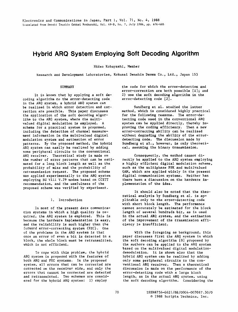
i' 'i+l and fi to be estimated for 4 and 6 A i+l i can be determined as indicated in Table 2 , by utilizing the properties of 4DPSK. The error patterns shown in Table 1 assume that the demodulation error can occur only be- tween the adjacent signal regions, andno de- modulation error occurs over two consecutive elements. These assumptions are satisfied with a high probability when the signal-to- noise power ratio (S/N) is relatively high.
It is seen from Table 2 that there can be only four estimated error patterns, which are (OlOl), ( O l l O ) , (1001) and (1010). Rep- resenting those by polynomials, ing expressions are obtained:
x 2 i - 1 + 5 2 i + l
z2i-1 + , 2 i
5 2 i - 2 + 5 2 i + l
5 2 i - 2 + 5 2 i I ?(a =
Since the received signal
the follow-
is de- scrambled, the effect of descrambling must be taken into consideration for the esti- mated error patterns given by Eq. (17 ) . In this case, the estimated error pattern ED(x)
7 4
Table 2 . Error estimation pattern in 4DPSK system
-7 r /2
n / 2
0 0 1 0 1 0 n / 2 1 0 A /2 0 1
7r 0 1 7r 1 0 [37r/2 1 0 37r/2 0 1
+ , Z i + Z 4
5 2 i - 1 + , 2 6 + , Z i + 4 + z 2 i + S + , 2 i + 2 2
+ x Z i + 2 4
z 2 i - 2 +,Zi +,Z-+8 + x 2 i + 6 f X Z i + 2 1
+ & i + Z 3 I As seen from Eq. (19), the demodulation error of an element on the channel is spread to the 6-bit error through the descrambler.
Thus, the estimated error pattern for the correction of the demodulation error of a modulation element in a block can be deter- mined as in Eq. (191, by the relation given in Table 2 . The estimated error pattern for the demodulation error over two or three modulation elements in a block can be syn- thesized from the estimated error patterns for the single element error, as in the case of Eqs. ( 6 ) to (8). Consider, for example, one to three errors of 6 bits in a block. The error can be corrected using Eq. (19) and estimating the error patterns corresponding to Eqs. ( 6 ) to (8).
Thus, for the block for which an error is detected, the error pattern can be
estimated using the channel-measurement in- formation ( a , B) and the orthogonal detected components ( x , y ) . The analog information (a, B) can be determined from the orthogonal detected components (z, y ) . Consequently, the proposed hybrid ARQ system can be real- ized by taking out and processing the ortho- gonal detected components from the demodula- tor of the conventional ARQ system. In this paper, the estimation of the error pattern is described for the 4DPSK system. In this case, the channel-measurement information B corresponds to the phase error of the de- tected output. By contrast, in the QAM sys- tem, for example, B can be considered as the amplitude error in the orthogonal detector output, and the error pattern can be esti- mated in the same way as was discussed in this section.
3 . Theoretical Analysis
This section assumes the hybrid ARQ system using binary transmission as the modu- lation scheme and the cyclic redundancy- check code (CRC) as the error-detecting code, as was described in Sect. 2 . A theo- retical analysis of the improvement is made from a theoretical viewpoint.
3.1 Analysis
The error correction of up to 3 bits in a block is considered in the estimation of error patterns, and Eqs. (6) t o (8) are employed. As the generator polynomial for the CRC code used in the analysis, the fol- lowing expression of 16th-order is employed:
In this case the error-detecting abil- ity is such that all errors up to 3 bits, as well as all errors in the odd bits in a block, can be detected. Based on the fore- going assumption, the number of error pat- terns to be estimated, the miss probability and retransmission request probability are calculated in the following.
In the proposed decoding algorithm, the
miss probability $E and the retransmission
request probability $& are represented as follows:
P& = P3
In the conventional ARQ system, the C miss probability PUE and the retransmission
75

C request probability PRE are represented as f o l l o w s :
P& = P i (23)
where P to P are as follows: 1 4
P l : the miss probability in the con-
ventional ARQ system; P 2 : the additional miss probability
produced by the hybrid realiza- tion of ARQ system;
bility in the hybrid ARQ system; and
P 3 : the retransmission request proba-
P 4 : block error probability.
P i s represented as follows: 4
P, = 1 - ( 1 - P e l " (25)
P is the bit error rate in the channel, and
y1 is the number of bits in a block. C
The probabilities P1 to P3 are shown i n Table 3, where m is the number of error bits in a block. In Table 3 P(m) is the probability that m bit errors are produced in a block, which is represented as follows:
P (4 = .c, ( 1 - Pc)*-m * PT (26)
( J ) , P g ) and P h i ) represent, respec- tively, the probabilities that 1, 2 and 3 bit
errors in a block can be corrected using the estimated error patterns of Eqs. ( 6 ) to ( 8 ) . They are given as follows:
( J rn Q (s) d s ) n-1- i d z
where q ( x ) i s the probability density func- tion, considering the additive white noise, which is given as follows:
0' is the noise power and A is the trans- mitted signal level.
In Table 3 Rll is the probability that 3-bit error-correcting manipulation is ap- plied to a single-bit error, resulting in a 4-bit error. It is given as follows (see Appendix 1):
Table 3 . Probabilities PI, P2 and P3 for m-bit error
76

R Z 1 , RZ2 and R23 represent the probabilities that the 2-bit error-correcting manipulation is applied to a 2-bit error, resulting in a 4-bit error. They are given as follows (see Appendix 2):
R, = Pi:)/ P (2 ) (32)
The theoretical discussion in this section is made assuming that the miss proba- bility for the even-bit error of 4 or more
bits in a block is l d 5 (see Appendix 3 ) . Ply P and P are determined from Table 3 as
follows : 2 3
( 3 5 )
Using Eqs. ( 3 5 ) to (371, the miss probabili- ties and the retransmission request proba- bilities in the conventional and the hybrid ARQ systems can be calculated.
3.2 Result of calculation
From the viewpoint of hardware reali- zation, the values of J , K and L to determine the number of error patterns to be estimated should be as small as possible. On the other hand, it is anticipated from the theo- retical analysis in the previous section that the error-correcting ability will increase with the number of estimated error patterns, at the same time increasing the miss proba- bility. This section discusses the miss and retransmission request probabilities as func- tions of J , K and L .
Figures 4 and 5 show the results of calculation for the miss and retransmission request probabilities as functions of J , K and L , for the information bit length of 512. It is seen from Figs. 4 and 5 that the re- transmission request probability is improved little if the value of K to determine the number of error patterns to be estimated f o r
-J
Fig. 4 . Probability of P& vs. J , K and L .
k=512bits
2 3 4 5 6 7 8 9 10
-J
Fig. 5. Probability of { E vs. J , K and L .
the 2-error correction is increased beyond 3 , while the miss probability increases rapidly when K exceeds 4 . When the value of L to determine the number of error patterns to be
77

estimated for 3-error correction is increased to 3, the miss probability increases, while the retransmission probability does not change much compared with the case of K = 3 and L = 0.
Figure 6 shows the miss and retransmis- sion probabilities as functions of E / N (signal-to-noise power ratio), in comparison with the conventional ARQ system. of simulation for the retransmission request probability is also shown in the figure. It is seen from Fig. 6 that the retransmission request probability is little improved if the value of J to determine the number of error patterns for single error correction is in- creased beyond 5.
b o
The result
By the foregoing results, it is con- cluded that J , K and L should be set as 5, 3 and 0, respectively. In this case, there are eight error patterns in total to be esti- mated. By this choice of parameters, the re- transmission request probability can be im- proved by approximately 3 dB, compared with the conventional scheme. On the other hand, the miss probability is increased by approxi- mately 1 dB. Thus, it is seen that the pro- posed decoding algorithm can improve drastic- ally the retransmission request probability at a little sacrifice of the excellent error- detecting ability of CRC code. It is seen from the result of simulation that the pre- sented theoretical analysis is effective also for long block length.
imulation Results
Eb/No (dB)
Fig. 6. Probability of PuE and PRE vs. E I N b 0'
4 . Experimental System
To verify the features of the proposed hybrid and ARQ system, an experimental sys- tem was constructed. A s the modem in the experimental system, V.29 of CCITT recommen- dation was used, which is used widely in the digital facsimile in telephone lines, for example. V.29 has both functions of 4- phase DPSK (4800 bps) and 16-valued (9600 bps).
The error correction unit in the ex- perimental system receives the quantized orthogonal detected components (x, y) from the demodulator of the V.29 modem. Using the orthogonal components, the detection of channel-measurement information and estima- tion of error pattern are performed by the methods described in Sect. 2. The informa- tion bit length in the encoder can be set as 512, 1024 or 2048. The values of J , K and L can be independently set up to 5, consid- ering the result of theoretical discussions in Sect. 3.2.
4.1 Result of experiment
Figure 7 shows the result of experi- ment for the relation between the retrans- mission request probability and J , K , L ,
10"
(
C
.: 10 ' v) .- E v) C
L Y
2 % 10' x Y .- I .- n n
a L
10 .'
10
Noise Bandwidth =3.1 kHz
o K = O , L=O O K = 2 , L=O
K - 3 , L=O A K = 4 , L = o x K = 3 , L = 3
u 1 2 3 4 5
-J
Fig. 7. Probability of <E vs. J , K and L
(experimental results).

for the case of 4-phase DPSK. The noise bandwidth is set as 3.1 kHz. It is seen from Fig. 7 that the result is almost the same as the theoretical result for the bi- nary transmission. In other words, by set- ting that J = 5 for single-error correction and K = 3 for 2-error correction, the re- transmission request probability almost con- verges. correction, the retransmission request pro- bability is improved little.
Even if L is set as 3 for 3-error
Figure 8 shows the test result for the retransmission request probability as a
10”
lo-‘
L a 10-6
lo-’
Noise Bandwid th=3 .1 k H z
4800bps (4DPSK) k =512 bits
Convent iona l A R Q
*--a Hybr id ARQ
1(111111111111 10 1 2 14 16 18 20 2 2
S / N (dB)
Fig. 8. Probability of P& and <E vs. SIN
(experimental results).
function of SIN, where the noise bandwidth is set as 3.1 kHz. The information bit length is set as 512 for 4-phase DPSK and 1024 for 16-valued QAM. It is set that J = 5, K = 3 and L = 0, and in total, there are eight error patterns to be estimated.
It is seen from Fig. 8 that the re- transmission request probability is improved by approximately 3 dB by applying the pro- posed decoding algorithm. On the other hand, a sufficient number of data was not acquired to evaluate the miss probability. Estimating from the theoretical discussion on the binary transmission system given in Sect. 3 , the miss probability can be sup-
pressed below lo-’ for the channel with the block error rate of which is satisfac- tory in practice.
It is seen from Fig. 8 that the re- transmission request probability is improved by approximately 3 dB by applying the pro- posed decoding algorithm. On the other hand, a sufficient number of data was not acquired to evaluate the miss probability. Estimating from the theoretical discussion on the binary transmission system given in Sect. 3, the miss probability can be sup- pressed below 10 for the channel with the
block error rate of which is satisfac- tory in practice.
-9
4.2 Application to HDLC procedure
This section discusses.the application of the proposed decoding algorithm to the REJ scheme [5] in the HDLC (high-level data link control) procedure. Figure 9 shows the result of theoretical calculation for the trasnmission throughput efficiency for the REJ scheme, utilizing the result of Fig. 8. The processing time required in the error correction by the proposed decoding algorithm
Fig. 9. Throughput efficiency.
7 9
is assumed to be the same as the transmis- s i o n time for one block, and the number M of outstanding frames is assumed as one larger than the conventional REJ scheme. It is seen from Fig. 9 that the hybrid ARQ system em- ploying the proposed decoding algorithm can improve drastically the throughput efficiency compared with the conventional system, where the error is detected and then retransmission is made.
5. Conclusions
This paper discussed the ARQ system with soft decoding algorithm, employing the multivalued digital modulation scheme. For the case where the multivalued digital modu- lation is employed, the detection of the channel-measurement information, as well as the estimation of the error pattern for the case where the input data are differentially encoded and scrambled, are proposed.
The proposed method is very practical, where the hybrid ARQ system is realized by taking out and processing the orthogonal de- tected components from the conventional ARQ decoder. A theoretical analysis is presented for the large block length, which is actu- ally employed in the ARQ system. The rela- tion among the number of error patterns to be estimated, miss probability, and the re- transmission request probability are investi- gated. An experimental system was actually constructed for the proposed method, and the usefulness of the method was verified by ex- periment.
The hybrid ARQ system proposed in this paper will especially be effective in the
satellite channel, where the additive white noise is the dominant factor in the degrada- tion of the signal quality, and there exists a large propagation delay.
Acknowledgement. The author appre- ciates the suggestions of Dr. Kaji, Presi- dent, Dr. Nosaka, Vice-president, Dr. Mura- tani, Deputy Director, Dr. Okawa, Head of Radio Comm. System Lab., KDD Lab. He also acknowledges the suggestions of Dr. Yana- gidaira, and the assistance in the construc- tion of the hybrid ARQ system by members of Mitsubishi Co.
1.
2.
3 .
4 .
5.
6.
REFERENCES
A.R.K. Sastry. Performance of Hybrid Error Control Schemes on Satellite Chan- nels, I.E.E.E. Trans. Commun., COM-23, 7, pp. 689-694 (July 1975). C.W. Sundberg. A Class of Soft Deci- sion Error Detectors for the Gaussian Channel, I.E.E.E. Trans. Commun., COM-24, 1, pp. 106-112 (Jan. 1976). H. Kobayashi, H. Yanagidaira, S. Shin- tani and K. Kawai. Application of Wag- ner code to multiphase modulation sys- tem, Trans. (B) I.E.C.E., Japan, J66-B, 10, pp. 1215-1222 (Oct. 1983). CCITT recommendations, Yellow Book Vol. VIII. W. Bux, K. Kummerle and H.L. Truong. Balanced HDLC Procedures: A Perform- ance Analysis, I.E.E.E. Trans. Commun.,
Ito and Maeda. Analysis of miss proba- bility frame in HDLC, Nat. Conv. I.E.C.E., Japan, No. 1571 (1980).
COM-28, 11, pp. 1889-1898 (Nov. 1980).
APPENDIX
1. Definition of RI,
Let the location of the single error bit in theblockbe II; RI1 is the probability that L bit locations for 3-error correction set by E q . (5) are in the following relation to I p
I , a ( 2 1 , 2 2 , ..'... 9 t L 1 ( A l )
2 . Definitions of Re, , R22 and 4,
are the probabilities that the locations of K bits for 2-error correction set by Eq. (5) are in the following relations to Il and 12:
80

Table Al. Miss probability of CRC code
Block Length
2 o o
Number of Error B i t s 6 8 1 0
3.1 2x 10⁻⁶ 3.0 3 x 10⁻⁵ 2.80 x 10⁻⁶ 3 89x10-6
(3 .73~10-6 ) 2 89x10-6
4 0 0 1(2.84x10⁻⁶) I 3 . 2 8 ~ 1 0 - 6
5 0 0
3 14x10-6 2 .68~10-6
600
2 79x10-6 (2 94x10-6)
3 05x10-6
8 0 0
1 0 0
3 24x10-6 2 .95~10-6
I 3 3 5 x 1 0 4 2 85x10-6 /3.08x10-6 I t.-LU "
1 3 lOxlO- ' / 3 . 0 7 ~ 1 0 - 6 3 23x10-6 I I X 1u-"
( 0 ) Exact Value
3 . Miss Probability of CRC Code
Several studies have been made on the miss probability of the CRC code in the ran- dom error channel, but a theoretical method has not been presented. Reference [6] pre- sented a quantitative discussion on the 4 - bit error in a block, using a computer, and concluded that the miss probability of CRC code of 16th-order is approximately 112 . 15
-- - 3 . 0 5 ~ 1 0 - ~ 2 ' 6
However, no result has been given for the 6, 8 and 10-bit errors. In this paper, to ob- tain a rough measure for the miss probabil- ity, random errors were generated by 4 , 6, 8 and 10 bits in a block, and the miss prob- ability is determined by computer simulation. The result is shown in Table A1 where it is seen that the miss probability can be ap- proximated by l d 5 also for 6, 8 and 10- bit errors.
AUTHOR
Hideo Kobayashi received B.E. and M.S. from Tohoku University, Sendai Japan, in 1975 and 1977, respectively. Since 1977 he has been with the R ti D Labs. of KDD, Tokyo, Japan, where he has been engaged in research on digital satellite communication systems, especially on high-performance digital modulation technique.
81