Embed Size (px)
Citation preview

Hybrid kinoform fanout holograms in dichromated gelatin
Brian Robertson,Antti Vasara
Jari Turunen, Hiroyuki Ichikawa, J. Michael Miller, Mohammad R. Taghizadeh, and
The technique for fabricating hybrid holograms, introduced by Bartelt and Case [Appl. Opt. 21, 2886 (1982)],is applied here to record extremely high-efficiency (>90%) space-invariant fanout holograms in dichromatedgelatin. The object wave front corresponding to that produced by a kinoform with a continuous-phase profileis derived by appropriate spatial filtering from a binary computer-generated hologram fabricated usingelectron-beam lithography.
1. Introduction
Kinoforms1 with continuous-phase profiles can theo-retically reconstruct arrays of equal-intensity lightspots with a diffraction efficiency approaching 100%.24These computer-generated holographic (CGH) grat-ings are therefore ideal optical elements in such appli-cations as array generation in digital optical comput-ing (for a comprehensive review of optical arraygenerators, see Ref. 5). The fabrication of opticalelements with continuous surface-relief or refractive-index profiles is unfortunately an extremely demand-ing task. Much of the recent research in the field ofarray generation has therefore been devoted to thedesign of kinoforms with only a few discrete, equallyspaced phase levels (see, e.g., Refs. 4 and 6-11), sincesuch holograms can, at least in principle, be fabricatedstraightforwardly using standard microlithographictechnology. The main problem with this approach isthat it requires nonstandard etch depth accuracy.
Recently, promising results have been obtained inrecording continuous-phase kinoforms on photoresistas surface-relief gratings using controlled laser-beamexposure.3 In this paper, a technique for recordingcontinuous-phase profiles is demonstrated, which isbased on the concept of the hybrid hologram.12 This is
A. Vasara is with the Department of Technical Physics, HelsinkiUniversity of Technology, 02150 Espoo, Finland. The other authorsare with the Department of Physics, Heriot-Watt University, Ric-carton, Edinburgh EH14 4AS, UK.
Received 9 October 1990.0003-6935/91/263711-10$05.00/0.© 1991 Optical Society of America.
a volume phase hologram recorded optically using aplane reference wave and an object wave generated,with the aid of spatial filtering, by a binary CGH (seeFig. 1). The phase profile of the kinoform is coded inthe form of pulse width and pulse density variations onthe CGH.
The optimization and the potential performance ofcontinuous-phase kinoforms are discussed in SectionII. Coding of the kinoform profile in binary form andthe effects of fabrication errors that occur when plot-ting the mask are analyzed numerically in Section III.In Section IV, the effects of spatial filtering and thenonlinearity of the recording material are investigated.Experimental results for a fanout hologram designedto generate an array of 1 X 8 spots, recorded in dichro-mated gelatin (DCG), are discussed in Section V. Thearray uniformity (defined as the maximum deviationof signal beam intensity from the average value) ob-tained in the first experiments is better than ±4%, theoverall diffraction efficiency of the interferometricDCG copy being 88% of the incident power. A mere 4%of the light appears in the unwanted high diffractionorders, which allows for an unlimited working field(within the angular acceptance of the volume grating).
II. Kinoforms with Continuous-Phase Profiles
We consider in this section the properties of phase-only gratings with trapezoidal phase profiles (see Fig.2) of the form
¢(x) = 01 + L(0 1+1 - 01)(x - IL), x [I/L, (1 + 1)/L), (1)
where = 0,..., L - 1, 01 = 0(1/L), and we havenormalized the grating period to unity. The ampli-tudes of the diffraction orders of this grating are givenanalytically by the Fourier coefficients of the gratingprofile. For order m we obtain
10 September 1991 / Vol. 30, No. 26 / APPLIED OPTICS 3711

CGH -2 Li SF L, DCG
f, ff- 2 ':-f f2 -
Fig. 1. Experimental setup for recording a hybrid hologram. CGHis a computer-generated hologram with the kinoform profile codedinto pulse width and pulse density variations of a binary-amplitudecarrier grating; -2,..., 2 denote the diffraction orders of the carriergrating. L and L2 are lenses with focal lengths f1 and f2. SF is aspatial filter that effectively passes through the first order of thecarrier grating while blocking the others. DCG is a volume holo-graphic plate.
*1
¢ (x) g '
0 /L 2/L (1-1)/L i/L (1+)/L (L-2)/L (L-1)/L 1
X
Fig. 2. General form of the phase profile considered in this work.
L-lU = (7rL)i E sinc[(B -27rm)/2lrL]
1=0
X expli[o, + B,/2L - rm(21 + 1)/L]}. (2)
Here we used the abbreviations B1 = L(0 1 +1 -Ok) andsinc(x) = sin(7rx)/7rx.
Our purpose is to equalize the intensities Pm = I UmJ2of the N = M 2 - M, + 1 adjacent orders m =M1,.. , M2 by controlling the grating profile. To thisend, we need L N independent phase values l ormore. Moreover, we wish to maximize the diffractionefficiency, i.e., the amount of incident power diffractedinto the desired orders. Therefore, to characterize thequality of the solution, we define a merit function as
M2~~~~~~
Mf (Pm -PIN)2 (3)m=M
where P e [0, 1] denotes the goal diffraction efficiency(e.g., Ref. 13). The initial choice of the goal efficiencywas typically 97%; if the grating efficiency failed toapproach this value during the design process, a lowergoal efficiency was substituted to achieve an arrayuniformity of better than 1%. (Owing to the form ofthe merit function, the uniformity does not convergebelow a certain limit if the goal efficiency is too high.)
A wide range of nonlinear optimization methods is
Table 1. Diffraction Efficiencies of Various Kinoform Solutions with Oddand Even Fanout
N PE N PE
3 92.6 2 8/r 2
5 92.6 4 91.97 93.5 8 96.09 99.2 16 94.3
11 97.6 32 95.313 97.4 64 96.515 97.0 128 96.4
available for minimizing Mf. The calculations leadingto the results in Table I were performed using theprocedure outlined below. The algorithm consists oftwo major steps, i.e., finding an approximate solutionusing an approximate merit function that is quick toevaluate and a refinement step with the merit functionthat describes the kinoform profile of Eq. (1) exactly.
In the first step, the grating period was divided into aset of L cells of equal width with a constant phase Olwithin each cell as in Ref. 13. An initial sinusoidaldistribution of phases was substituted, and the meritfunction, Eq. (3), was evaluated. A trial change ofeither Ai or -A was applied to the phase value cj ofeach cell sequentially ( = 0, . . , L - 1), and thechange was accepted only if the merit function de-creased. This process was performed cyclically untilthe number of changes accepted during a single cycle ofshifting all phases once fell below a predeterminedlimit, usually L/20. Next, the value of the trial changewas halved, and the iteration process described abovewas repeated. The initial value of the trial change wastypically 0.5 rad, and we typically performed three tofive iteration steps of this kind.
After these three to five iterations, the rate of in-crease of the diffraction efficiency slowed down con-siderably, while the uniformity had reached a value ofapproximately 1%. At this stage, the program shiftedinto a refinement algorithm, which calculated the mer-it function using the exact Eq. (2) for the continuousprofile. This change reduced the uniformity to 5-10%,depending on N and the ratio LIN. The iterationprocess described above was repeated using the new,exact merit function, starting (typically) from a trialchange of 0.05 rad. Few iteration steps [(1)-(3)] wereneeded to obtain an acceptable uniformity (below 1%).The diffraction efficiency was also increased some-what as a result of this smoothing of the phase profile.The efficiencies of the solutions given in Table I arebelieved to be close to optimum, but slight improve-ments can be obtained by increasing the number ofcells (we used typically LIN = 4-10) and/or by con-tinuing the iteration.
The results for odd fanout N in Table I were calcu-lated by equalizing the N = 2M + 1 diffraction orders-M, . . . , M, whereas two different methods were usedto obtain solutions with even N. First, N = 2M orders-M+1 ... ,Mwereequalized. Second,N= 2Moddorders -2M + 1, . . , 2M - 1 alone were equalizedwhile keeping the even orders automatically at zerointensity by requiring that the phase profile +(x) satis-
3712 APPLIED OPTICS / Vol. 30, No. 26 / 10 September 1991
1.4 I
1.2 -
-x 0.8
0.6
0.4
0.2 lI I0 0.2 0.4 0.6
One period
Fig. 3. Profile of the kinoform generatingbeams in diffraction orders -3,..., 4.
0.8
eight equal-intensity
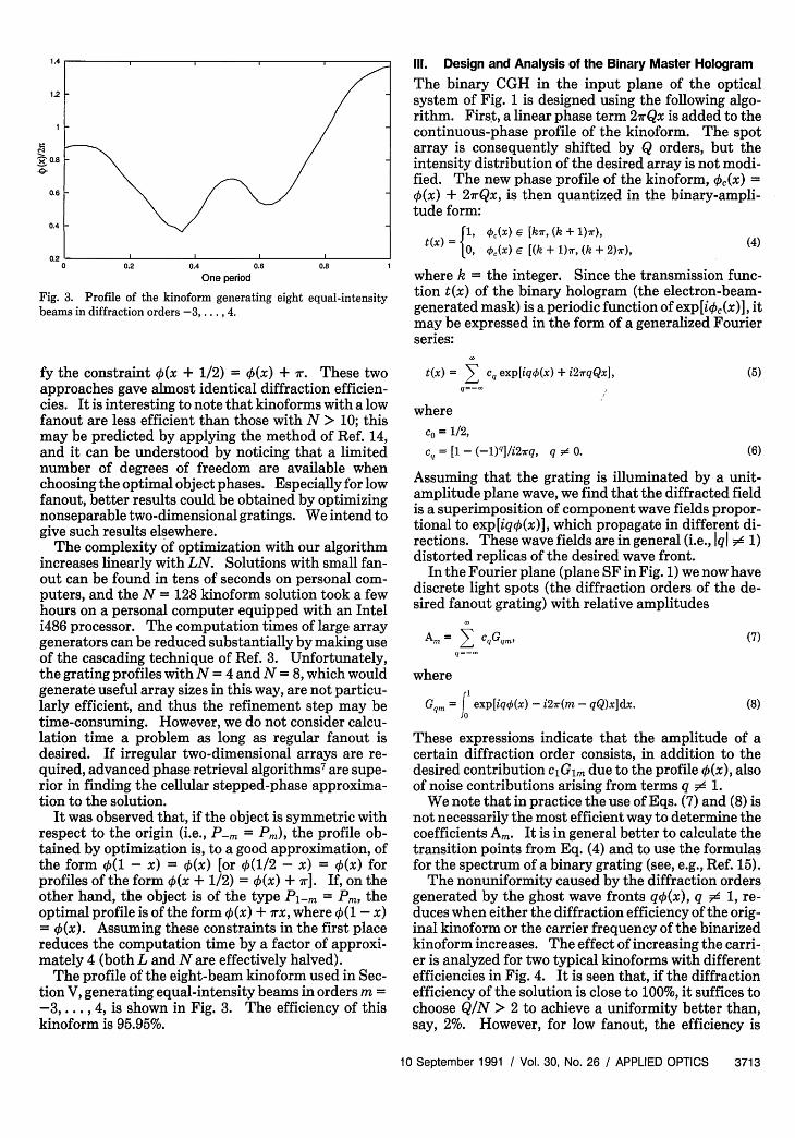
111. Design and Analysis of the Binary Master Hologram
The binary CGH in the input plane of the opticalsystem of Fig. 1 is designed using the following algo-rithm. First, a linear phase term 2 7rQx is added to thecontinuous-phase profile of the kinoform. The spotarray is consequently shifted by Q orders, but theintensity distribution of the desired array is not modi-fied. The new phase profile of the kinoform, '.(x) =0(x) + 27rQx, is then quantized in the binary-ampli-tude form:
OX : =I (X) [r, (k + 1)7r),t(x) = ,(x) e [(k + 1)ir, (k + 2)ir), (4)
where k = the integer. Since the transmission func-tion t(x) of the binary hologram (the electron-beam-generated mask) is a periodic function of exp[i5,(x)], itmay be expressed in the form of a generalized Fourierseries:
fy the constraint 0(x + 1/2) = (x) + r. These twoapproaches gave almost identical diffraction efficien-cies. It is interesting to note that kinoforms with a lowfanout are less efficient than those with N > 10; thismay be predicted by applying the method of Ref. 14,and it can be understood by noticing that a limitednumber of degrees of freedom are available whenchoosing the optimal object phases. Especially for lowfanout, better results could be obtained by optimizingnonseparable two-dimensional gratings. We intend togive such results elsewhere.
The complexity of optimization with our algorithmincreases linearly with LN. Solutions with small fan-out can be found in tens of seconds on personal com-puters, and the N = 128 kinoform solution took a fewhours on a personal computer equipped with an Inteli486 processor. The computation times of large arraygenerators can be reduced substantially by making useof the cascading technique of Ref. 3. Unfortunately,the grating profiles with N = 4 and N = 8, which wouldgenerate useful array sizes in this way, are not particu-larly efficient, and thus the refinement step may betime-consuming. However, we do not consider calcu-lation time a problem as long as regular fanout isdesired. If irregular two-dimensional arrays are re-quired, advanced phase retrieval algorithms7 are supe-rior in finding the cellular stepped-phase approxima-tion to the solution.
It was observed that, if the object is symmetric withrespect to the origin (i.e., P-rn = Pm), the profile ob-tained by optimization is, to a good approximation, ofthe form 0(1 - x) = (x) [or 0(1/2 - x) = (x) forprofiles of the form 0(x + 1/2) = 0(x) + 7r]. If, on theother hand, the object is of the type P1_m = P theoptimal profile is of the form ¢ (x) + 7rx, where (1 - x)= 0(x). Assuming these constraints in the first placereduces the computation time by a factor of approxi-mately 4 (both L and N are effectively halved).
The profile of the eight-beam kinoform used in Sec-tion V, generating equal-intensity beams in orders m =-3,.. ., 4, is shown in Fig. 3. The efficiency of thiskinoform is 95.95%.
t(x) = cq exp[iq0(x) + i2rqQxj,
whereC = 1/2,
cq = [1 - (1)q]/i2rq, q 5 0.
(5)
(6)
Assuming that the grating is illuminated by a unit-amplitude plane wave, we find that the diffracted fieldis a superimposition of component wave fields propor-tional to exp[iq0(x)], which propagate in different di-rections. These wave fields are in general (i.e., Iq #d 1)distorted replicas of the desired wave front.
In the Fourier plane (plane SF in Fig. 1) we now havediscrete light spots (the diffraction orders of the de-sired fanout grating) with relative amplitudes
Am = Z CqGqm,
where
Gqm = f exp[iq0(x) - i2r(m - qQ)x]dx.
(7)
(8)
These expressions indicate that the amplitude of acertain diffraction order consists, in addition to thedesired contribution ciGim due to the profile 0(x), alsoof noise contributions arising from terms q 1.
We note that in practice the use of Eqs. (7) and (8) isnot necessarily the most efficient way to determine thecoefficients Am. It is in general better to calculate thetransition points from Eq. (4) and to use the formulasfor the spectrum of a binary grating (see, e.g., Ref. 15).
The nonuniformity caused by the diffraction ordersgenerated by the ghost wave fronts qq(x), q d 1, re-duces when either the diffraction efficiency of the orig-inal kinoform or the carrier frequency of the binarizedkinoform increases. The effect of increasing the carri-er is analyzed for two typical kinoforms with differentefficiencies in Fig. 4. It is seen that, if the diffractionefficiency of the solution is close to 100%, it suffices tochoose QIN > 2 to achieve a uniformity better than,say, 2%. However, for low fanout, the efficiency is
10 September 1991 / Vol. 30, No. 26 / APPLIED OPTICS 3713

05 10 20
Q
Fig. 4. Array uniformities given by two kinofunction of the carrier 27rQx. Open circles: eiefficiency, 95.95%. Solid circles: nine beams,99.1%.
50 100
form solutions as aight beams; original, original efficiency,
typically in the 92-96% range (see Table I), and one isforced to choose a high value of QIN (>10).
The transition point positions of the binary CGHcan be optimized to improve the uniformity arbitrari-ly. Whether this will improve the quality of the DCGcopy is not immediately clear, since the spatially fil-tered wave front in the DCG plane is modified duringoptimization, and the profile that is finally recon-structed does not necessarily approach the original0(x). This is discussed in more detail in Section IV.
One should also note that amplitude variations areintroduced in the process of spatial filtering. Everyphase-only grating has an infinite number of nonzeroFourier coefficients (in practice these generate only afinite number of propagating diffraction orders).Therefore the desired contribution cannot be totallyseparated from the noise however large the value of Qis. How significant these intensity variations will bedepends primarily on the width of the spatial filter(which passes orders Q + M'l, . . , Q + M'2 throughwhile blocking the others), but it also depends on thediffraction efficiency of the original kinoform. Theseeffects are also analyzed numerically in the followingsection. We note that it may be possible to remove thehigher orders by introducing a slight amount of ab-sorption in the hologram structure before binarization.
With high values of QIN (in practice with QIN > 2),the derivative dk(x)/dx is small everywhere comparedto the slope 27rQ of the carrier, and the phase profilek0 (x) thus appears almost linear. In these conditions,
the number of fringes (transition point pairs) withinone grating period is approximately equal to Q, and theaverage feature size is T/2Q, where T is the gratingperiod. The smallest feature size is typically close tothe average feature size.
We conclude this section by analyzing the fabrica-tion accuracy required in recording the CGH toachieve a satisfactory array uniformity in plane SF ofFig. 1. To this end, we optimized the transition pointsof the binary eight-beam masks for several values ofthe carrier Q to eliminate the effects caused by the
Table II. Array Uniformity as a Function of the Fabrication Error and theCarrier 0 for the Eight-Beam Klnoform Solution: the Expectation Value
and the Standard Deviation of the Slope C In AR = CNAXmaxd
Q (C) SD(C)
10 750 25020 1075 39030 1375 50050 1475 52575 1925 600
120 2625 825250 6375 2750
overlap of the undesired high carrier orders. Randomnoise, Axp E [-AXmax, AXmax], was then added to alltransition points xp in the mask. Using fifty noiserealizations for each mask and several values of AXmax,we established that the uniformity (expressed in per-cent) is of the form AR = CNAxmax/d, where d nowdenotes the grating period that was normalized to uni-ty above. The value of the dimensionless slope Cdepends strongly on the carrier frequency; increasingit will therefore tighten the manufacturing tolerances.Since increasing Q improves the uniformity in theabsence of fabrication errors, an optimum value of thecarrier exists. This value depends on the diffractionefficiency of the continuous grating solution, the num-ber of beams in the array, and the grating period andmust in general be evaluated numerically in each case.The expectation value and the standard deviation ofthe array uniformity for the eight-beam kinoformmask are given in Table II as a function of the carrier.
IV. Nonlinear Effects in Recording the Hybrid Hologram
The field distribution in the plane of the DCG plate,produced by the N' = M 2 - M'l + 1 diffracted orderstransmitted by the spatial filter, is given by the expres-sion
Q+M 2'
V(x) = E Am exp[i27r(Q - m)x]. (9)m=Q+M',
Here we have compensated for the tilt between thepropagation direction of the incident wave and theorientation of the DCG plate by introducing the termexp(-i27rQx).
As a result of spatial filtering, the field distributionU(x) can no longer be phase only. (It could be strictlyphase only, i.e., binary phase, only if the order m = 0alone were filtered out; see Ref. 16.) DCG cannotrecord this amplitude information linearly if high dif-fraction efficiency is required,'2' 1 7 whereas the phaseinformation is recorded with excellent accuracy. Lin-ear recording of the amplitude information could beachieved at the expense of diffraction efficiency as inRef. 12, but loss of efficiency is precisely what we wishto avoid. Therefore the copying procedure will neces-sarily alter the intensity distribution in the final array.To estimate the order of magnitude of the effects ofthis distortion, we assume that the amplitude informa-tion is totally discarded, which may occur if the ampli-tude variations are small and DCG is saturated (seeFig. 4 of Ref. 12). In these circumstances, the phase
3714 APPLIED OPTICS / Vol. 30, No. 26 / 10 September 1991
0.2
0.15 F_
0.1 I_0r~
C
0.05
I.
0
~II
, -- *6 _-* -------

0.8
0.6
0.4
0.2
00 0.2 0.4 0.6 0.8
One period
Fig. 5. Amplitude variations in the DCG plane of Fig. 1 caused bythe SF as a function of the number of diffraction orders passedthrough. Eight-beam kinoform with efficiency of 95.95%, carrier Q= 120. Dashed line, 8 orders; dashed-dotted line, 20 orders; solidline, 500 orders.
1,
0.8 -
* 0.6
._
E< 0.4
0.2 1-
0 0.2 0.4 0.6 0.8One period
0
Fig. 6. Same as Fig. 5 but for a nine-beam kinoform with efficiencyof 99.1% and carrier Q = 20. Dashed line, 9 orders; dashed-dottedline, 19 orders; solid line, 39 orders.
1.2
0.8
IL
0.4
0.2
0 0.2 0.4 0.6 0.8One period
Fig. 7. Phase profile in the DCG plane caused by spatial filtering asa function of the number of diffraction orders passed through.Eight-beam kinoform. Dashed-dotted line, 8 orders; solid line, 500orders. This is indistinguishable from the original phase profile inthe scale shown.
1.2
r 0.8
CO 0.6
EL
0.4
0.2
00 0.2 0.4 0.6 0.8
One period
Fig. 8. Same as Fig. 7 but for the high-efficiency nine-beam solu-tion. Dashed line, 9 orders; solid line, 39 orders.
profile reconstructed by the DCG hologram is of theform q!DCG(x) = arctanJIm[V(x)]/Re[V(x)]}, where Reand Im represent the real and the imaginary parts ofV(x) [given by Eq. (9)]. The amplitudes of the finaldiffraction orders produced by the DCG copy are, ne-glecting other sources of error such as the Bragg angleselectivity, given by the Fourier coefficients:
F = exp[iODCG(x) - i2irmxjdx. (10)
No simple relationship exists between the coefficientsFm and Am, and numerical methods must therefore beapplied to investigate the reconstruction fidelity.
Figures 5 and 6 show the dependence of the ampli-tude variations in the DCG plane on the number ofdiffraction orders passed through the spatial filter.Two different kinoform solutions are considered:eight beams with 95.95% efficiency in Fig. 5 and ninebeams with 99.1% efficiency in Fig. 6. The value of Q is250 in Fig. 5 but only 20 in Fig. 6. It is observed thatsignificant amplitude variations take place in bothcases if only the desired diffraction orders are passed
through. The dip that is observed in Fig. 5 around x =0 and x = 1 is due to the functional form (x) + rx, 4 (x)- 0(1 - x) of the phase profile. This dip is not ob-served in the profile produced by a mask generatingnine beams, since the original design profile does notcontain the abrupt jump.
The phase profiles generated by the spatially fil-tered binary CGHs corresponding to the two kino-forms are compared with the desired profiles in Figs. 7and 8. It is seen that a small number of diffractionorders suffices to yield a good approximation of theoriginal phase profile. In Figs. 9 and 10 we display theresults corresponding to Figs. 5 and 7, obtained byreoptimizing the transition points of the mask to makeall eight desired orders equal in magnitude in the planeof the spatial filter (SF). The reoptimization is seen toalter both the amplitude and the phase profiles in anundesired manner, leading, e.g., to the appearance ofsharp dips. Array uniformity resulting from the phaseprofiles generated by the optimized and nonoptimizedeight-beam masks was calculated using Eq. (10), andthe results are shown in Fig. 11. When the eightdesired orders alone were retained, a uniformity of the
10 September 1991 / Vol. 30, No. 26 / APPLIED OPTICS 3715
I,''1 I
I,IDIC
'II'I'
F-
I I~~~~~~~~~~
I, '~~~~~~~~~~~~~~~~~~~~~~~~
X | X l l
1
1

0.8
W'aE
0.8
0.4
0.2
00.2 0.4 0.6
One period
Fig. 9. Same as Fig. 7 but with the transition pgenerate equal-intensity beams in the desired ordDashed line, 8 orders; dashed-dotted line, 20 ordorders.
1.2
i 0.8
a)Cl)CO 0.60
0.4
0.2
000 0.2 0.4 0.6
One period
Fig. 10. Same as Fig. 8 but with optimizedDashed line, 8 orders; solid line, 500 orders.
0.08
0.06
E
0.02
0 5 10 20 50 100
Number of orders passed
Fig. 11. Array uniformity produced by the DCGmized (solid circles) and an optimized (open cisponding to the eight-beam kinoform.
order of 6% was obtained in both cases.orders retained, the uniformity stabilizmately 3% for the nonoptimized solutiofor the optimized transition points are ring. If the number of diffraction through is in the 20-100 range (i.e., the d
10 do not appear in the phase profile smoothed by thesmall number of orders included), the array uniformityremains below 2%. However, if a larger number oforders are retained, the uniformity deteriorates mono-tonically.
We finally note that the model used in this section isfar from rigorous and is only aimed to give a generalidea of some phenomena that can be expected. Morethorough investigations that take into account the vol-ume effects are under way.
V. Experimental Results
0.8 1 A set of experiments was performed to verify the feasi-bility of the present copying technique. During the
oints optimized to copying process, the period of the kinoform was re-ders around m = Q. duced from 2500 zm (mask) to 998 + 2 zm (DCG copy)Lers; solid line, 500 by choosing fi = 2.5f2 in Fig. 1. Down-imaging of this
kind is a valuable benefit of the present technique,since it can be used to reduce the dimensions of thereconstruction setup, which is important in realizingminiature optical processing systems.
A binary-amplitude mask corresponding to the con-tinuous-phase profile of the kinoform generating eightequal-intensity diffraction orders (see Fig. 3) was fab-ricated using electron-beam lithography. We chose Q= 250, which implies a theoretical uniformity of 2.57%.With a grating period of 2.5 mm, the average featuresize is 5 m, and the smallest feature was 1.3 Am. Themask could therefore be easily manufactured with theelectron-beam writer capable of recording submicronfeatures. As expected, visual inspection of the mask
0.8 l by an optical microscope revealed a regular Ronchi-grating-like pattern.
transition points. . Assuming that the absolute positional accuracy ofthe electron-beam writer is, as specified, AXma = 0.1Am, direct numerical analysis gave an expectation val-ue of 3.4% for uniformity, the standard deviation being0.5%. (These values contain contributions from boththe overlap of higher carrier orders and fabricationerrors.) The actual uniformity of the array generatedby the mask was found to be slightly better than ex-pected, i.e., 2.8%, indicating that the accuracy of thewriter may exceed the specifications.
_ ¢_ Intensity profiles produced by the mask in the DCGplane were measured using a scanning slit and a photo-diode. These results are shown in Fig. 12. Figure12(a) shows the object wave front generated when thespatial filter was set to transmit approximately 200diffraction orders, while Fig. 12(b) gives the profile
200 500 generated when all but the eight desired central orderswere removed (see Fig. 5). Theoretical and experi-
rcopy of a nonopt- mental profiles are in good agreement, exhibiting, e.g.,identical numbers of maxima and minima and havingabout the same.relative amplitude variations.
A set of DCG copies was recorded at 488 nm usingWith over 20 the experimental system described in Fig. 1. The
;ed at approxi- object beam was aligned normal to the holographictn. The results plate, while the reference beam was incident at 300 toather interest- it. For all the holographic copies recorded, gelatinorders passed derived from Kodak 649F spectroscopic plates waslips seen in Fig. used. In addition, the preprocessing and processing
3716 APPLIED OPTICS / Vol. 30, No. 26 / 10 September 1991
A"
C -'
'C-.C -
'F
CI
'FC'
''''I I ..
_ \ , As~~~~~eC..~
II ^
I so
0.04

(a) (a)
(b)
Fig. 12. Intensity profiles produced by the binary-amplitude maskin the DCG plane as a function of the number of diffraction orderspassed through the spatial filter: (a) approximately 200 diffractionorders; (b) 8 diffraction orders.
(a)
(b)
Fig. 13. Array produced by the DCG copy with approximately 200orders included. The signal beams are correctly exposed in (a) andstrongly overexposed in (b).
techniques were based on those of Chang and Leon-ard.1 8
Owing to the almost uniform high-quality objectwave front, (Bragg) diffraction efficiencies of over 95%were easily obtained. Two photographs of the output
\ /e
(b)
Fig. 14. Intensity profiles of light that is passed through the DCGcopy: (a) approximately 200 diffraction orders and (b) 8 orders werecopied.
array generated by a DCG copy of the binary-ampli-tude CGH are shown in Fig.13. In Fig.13(a) the signalbeams are exposed correctly, and in Fig. 13(b) they arestrongly overexposed to show some of the faint higherorders. For this particular DCG copy, the gratingdiffraction efficiency was measured to be 96.3%, whileits real efficiency was 87.7%. Losses were due to Fres-nel reflection at the front face (5.8%; the DCG copy wassealed with an antireflection-coated cover plate tominimize reflection losses at the output face) and ab-sorption and scattering losses in the DCG, optical ce-ment, and cover plate (about 3%). The efficiency intothe central 8 orders was measured to be 96% of theBragg diffracted light, which agrees well with the95.95% efficiency of the original kinoform solution.Array uniformity of this high-efficiency copy was mea-sured to be 3.2%. This uniformity did not measurablyvary when the copy was replayed at longer wavelengths(514.5 and 633 nm), thus demonstrating the potentialto be used over a large range of frequencies. It wasnoticed, however, that there existed a slight depen-dence of the uniformity on replay angle. For example,a tilt of 1° could cause it to increase from 3.2 to 4.0%.In most practical interconnect applications, such asmall variation does not cause a problem.
Higher grating diffraction efficiencies of almost98.5% (real efficiency, 89.1%) were obtained; however,owing to saturation of the refractive-index modula-tion, the uniformity of the output grew slightly worse,increasing to 5%.
We also performed some initial experiments on re-cording an object wave front in which all but the 8central orders were filtered out. To investigate theeffects of saturation of the refractive-index modula-tion in the recording of the amplitude information, wemeasured the intensity profile of the wave front dif-fracted in the first Bragg angle. (To avoid interfer-ence by other Bragg orders, the measurement was ac-
10 September 1991 / Vol. 30, No. 26 / APPLIED OPTICS 3717
Ii

(II
1,1 II III II
I,
: 75I 70
, 65.I.D GO.00 55.
4 50." 450
W40.t' 35
30.25.20.15.
10.5-C,
Fig. 15. Intensity distribution of the spot array generated by theDCG copy with 200 orders included.
-15 -10 -5 6 o is15 1 0 1a 5Replay angle 25
Fig. 17. Angular acceptance of the DCG copy: zeroth-order poweras a function of the deviation of the replay angle from the exactBragg angle (0 in the figure).
is v
III 1,
I
I I
II
/ I
Fig. 16. Intensity profile of one spot in the array.
tually performed in the image plane of the DCGgrating.) The results in Fig. 14 show that the satura-tion is indeed significant: the amplitude variations inFig. 14(b) are considerably smaller than those in Fig.12(b). The array uniformity obtained in this prelimi-nary experiment was 37%, i.e., considerably larger thanthat predicted by the simple theory of the previoussection. This indicates that the model should be re-fined to obtain quantitative results if the object wavefront has large intensity variations.
To investigate the hologram's performance whenshifted to longer wavelengths, a DCG copy was re-played at 633 nm. A charge-coupled device scan of thespot array in Fig. 15 shows the intensity profile acrossthe central 8 orders, and Fig. 16 shows the spot profileof just 1 order. Owing to the finite number of the CCDpixels and their somewhat different sensitivities, thearray uniformity cannot be measured reliably fromFig. 15, but it shows that the (Rayleigh) compressionratio5 of the array is approximately 2.4: the measuredfull width of the spot, 66 Am A 3%, agrees well with thetheoretical value of 62 ,um. Similar work on copyingbinary-amplitude CGHs onto DCG16 shows that goodquality performance at 830 nm is also possible.
The intensity of the brightest undesired spot was
Fig. 18. Two-dimensional array obtained by crossing two one-di-mensional DOG copies.
approximately 5% of the signal beam power. This lowvalue is important in applications where a large work-ing field is required around the array. One way toachieve this goal is to optimize the surrounding ordersto zero power, as was done in Ref. 19 for binary grat-ings, but the diffraction efficiency in the array is thenreduced significantly. The second approach, whichwe prefer and have demonstrated here, is to design andto record a hologram with a high enough efficiency toensure that the unwanted orders are necessarily belowthe allowed noise threshold. The working field of ourhybrid holograms is limited only by the angular accep-tance of the volume grating. The angular acceptanceis approximately 1 in Fig. 17; it could, however, beincreased considerably by using a thinner gelatin layerand/or a larger Bragg grating period.
The technique described here is suitable for thegeneration of patterns considerably larger than the 1 X8 array demonstrated here. Masks for fanout up to N= 128 have been designed, and work is under way torealize a higher fanout. A large fanout may require ahigher carrier frequency. However, for the mask witha highly desirable fanout of N = 32 with Q = 250 andAx.a = 4 X 10⁻⁵ (this corresponds, e.g., to a .1-A.mpatterning accuracy and d = 2.5-mm grating period),the expectation value of the array uniformity is as lowas 3.1%.
3718 APPLIED OPTICS / Vol. 30, No. 26 / 10 September 1991
a~~~~~~~++4
+ + + +
+ + '++ ++ ++++ +*
+~~~~~~~~ +
+ ++ +
+ +
+ +
+
+ +
+ +4+
\

Two-dimensional arrays are easy to generate: twoone-dimensional CGHs are simply crossed to producethe object wave front. One of the CGHs should bebinary-phase, but the phase angle is not critical. Thecrossing of the one-dimensional gratings can also beperformed in the design phase as in the case of Dam-mann gratings. 2 It is also possible (although some-what awkward since they are off-axis) to cross twoDCG copies. The result of such an experiment isdisplayed in Fig. 18. We established that 85% of theincident light was diffracted in the desired 64 diffrac-tion orders.
VI. Conclusions
Previous work on copying CGHs on volume materialshas shown that significant advantages arise when use ismade of this hybrid technique. 16 2 0 21 One can, e.g.,combine an array generator with a focusing lens orrecord binary-phase holograms using a binary-ampli-tude mask to produce the object wave16 (thus avoidingthe critical etching step). Finally, one can modify thegrating period at will in the copying stage: Only onebinary-amplitude mask is needed for a given fanout.
We have demonstrated the additional capability ofthe hybrid technique to generate optical elements withaccurate continuous-phase profiles; such componentsare extremely difficult to manufacture using previous-ly known methods. In particular, we have demon-strated that highly efficient low-noise kinoform arraygenerators can be recorded interferometrically inDCG, using a spatially filtered output of a speciallydesigned CGH as the object wave.
It is interesting to compare the method discussedabove to the alternative multistep lithographic tech-nique. Both methods allow one to manufacture a largenumber of holograms on a single substrate. Stepped-phase kinoforms in, e.g., quartz are highly stable andresistant to heat and varying environmental condi-tions. Properly dried and sealed DCG holograms arealso immune to environmental conditions, and theyhave high damage thresholds against laser-inducedheating.2 0 Continuous-phase holograms have a some-what higher design efficiency, but this advantage isreduced by absorption in gelatin and the presence ofother Bragg orders. Therefore, the decisive factor willprobably be the ease and cost-effectiveness of manu-facturing these elements. The microlithographictechnology is well established, but the etching toler-ances are considerably tighter than in typical very-large-scale integration applications.
The fabrication of a stepped-phase kinoform with2 N phase levels requires N masks and etching steps,whereas the hybrid method requires only one mask, anoptical exposure, and the processing of the DCG plate.In addition, the present technique can easily be ex-tended to include the mass production of hybrid kino-forms in recently developed photopolymers,22 whichrequire less complex processing procedures than DCG.
The authors thank H. P. Herzig, F. Wyrowski, and0. Bryngdahl for interesting discussions during theICO-15 meeting and for providing Refs. 3 and 14. We
also thank J. Westerholm for help in optimizing thegrating solutions in Table I, and the EBLF group atRutherford Appleton Laboratory for fabricating theelectron-beam masks. Financial support from Pilk-ington plc, the Academy of Finland, The Royal Soci-ety, Finnish Cultural Foundation, The British Coun-cil, Jenny and Antti Wihuri Foundation, EmilAaltonen Foundation, and Alfred Kordelin Founda-tion is gratefully acknowledged.
References1. L. P. Lesem, P. M. Hirsch, and J. A. Jordan, "The kinoform: a
new wavefront reconstruction device," IBM J. Res. Dev. 13,150-155 (1969).
2. H. Dammann and K. Gortler, "High-efficiency multiple imagingby means of multiple phase gratings," Opt. Commun. 3,312-315(1971).
3. H. P. Herzig, "Design and fabrication of highly efficient fan-outelements," Jpn. J. Appl. Phys. 29, L1307-L1309 (1990).
4. A. Vasara, J. Turunen, J. Westerholm, and M. R. Taghizadeh,"Stepped-phase kinoforms," in Optics in Complex Systems, F.Lanzl, H.-J. Preuss, and G. Weigelt, eds., Proc. Soc. Photo-Opt.Instrum. Eng. 1319, 298-299 (1990).
5. N. Streibl, "Beamshaping with optical array generators," J.Mod. Opt. 36, 1559-1573 (1989).
6. H. Dammann, "Blazed synthetic phase-only holograms," Optik31, 95-104 (1970).
7. F. Wyrowski, "Diffractive optical elements: iterative calcula-tion of quantized, blazed phase structures," J. Opt. Soc. Am. A 7,961-969 (1990).
8. J. Turunen, J. Fagerholm, A. Vasara, and M. R. Taghizadeh,"Detour-phase kinoform interconnects: the concept and fabri-cation considerations," J. Opt. Soc. Am. A 7, 1202-1208 (1990).
9. S. J. Walker and J. Jahns, "Array generation with multilevelphase gratings," J. Opt. Soc. Am. A 7, 1509-1513 (1990).
10. J. N. Mait, "Design of binary-phase and multiphase fouriergratings for array generation," J. Opt. Soc. Am. A 7, 1514-1528(1990).
11. M. Ekberg, M. Larsson, S. Hard, and B. Nilsson, "Multilevelphase holograms manufactured by electron-beam lithography,"Opt. Lett. 15, 568-569 (1990).
12. H. Bartelt and S. K. Case, "High-efficiency hybrid computer-generated holograms," Appl. Opt. 21, 2886-2890 (1982).
13. J. Turunen, A. Vasara, and J. Westerholm, "Kinoform phaserelief synthesis: a stochastic method," Opt. Eng. 28, 1162-1167(1989).
14. F. Wyrowski, "Characteristics of diffractive optical elements/digital holograms," in Computer and Optically Formed Holo-graphic Optics, I. Cindrich and S. N. Lee, eds., Proc. Soc. Photo-Opt. Instrum. Eng. 1211, 2-11 (1990).
15. J. Turunen, A. Vasara, J. Westerholm, G. Jin, and A. Salin,"Optimization and fabrication of grating beamsplitters," J.Phys. D 21, S102-S105 (1988).
16. B. Robertson, M. R. Taghizadeh, J. Turunen, and A. Vasara,"High-efficiency, high bandwidth optical interconnects in dich-romated gelatin," Opt. Lett. 15, 694-696 (1990).
17. I. R. Redmond, "Holographic optical elements in dichromatedgelatin," Ph.D. dissertation (Heriot-Watt University, Edin-burgh, UK, 1989).
18. B. J. Chang and C. D. Leonard, "Dichromated gelatin for thefabrication of holographic optical elements," Appl. Opt. 14,2407-2417 (1979).
19. M. Heissmeyer, U. Krackhardt, and N. Streibl, "A Dammanngrating with diffraction orders of arbitrary intensity etched intoA12 03," Opt. Commun. 76, 103-106 (1990).
10 September 1991 / Vol. 30, No. 26 / APPLIED OPTICS 3719
20. B. Robertson, M. R. Taghizadeh, J. Turunen, and A. Vasara,"Fabrication of space-invariant fan-out components in dichro-mated gelatin," Appl. Opt. 29,1134-1141 (1990).
21. L. Wang, W.-Z. Ceng, and R. K. Kostuk, "Efficient multiple-image holographic optical element," Opt. Eng. 29, 257-262(1990).
22. W. K. Smothers, T. J. Trout, A. M. Weber, and D. J. Mickish,"Hologram recording in Dupont's new photopolymer material,"in Holographic Systems, Components, and Applications, Proc.Inst. Electr. Eng. 311, 184-189 (1989).
3720 APPLIED OPTICS / Vol. 30, No. 26 / 10 September 1991