Embed Size (px)
Citation preview
SSRG International Journal of Electrical and Electronics Engineering (SSRG-IJEEE) – volume 3 Issue 1 January 2016
ISSN: 2348 – 8379 www.internationaljournalssrg.org Page 17
Hybrid Neuro-Fuzzy controller based
Adaptive Neuro-Fuzzy Inference System
Approach for Multi-Area Load Frequency
Control of Interconnected Power System O Anil Kumar
1, Ch Rami Reddy
2
1pursuing M.Tech (EEE),
2working as Assistant Professor (EEE),
Nalanda Institute Of Engineering and Technology (NIET), Kantepudi(V), Sattenpalli(M), Guntur (D)-522438,
Andhra Pradesh.
Abstract- This paper concentrated on the design and
analysis of Neuro-Fuzzy controller based Adaptive
Neuro-Fuzzy inference system (ANFIS) architecture
for Load frequency control of interconnected areas,
to regulate the frequency deviation and power
deviations. Any mismatch between generation and
demand causes the system frequency to deviate from
its nominal value. Thus high frequency deviation
may lead to system collapse. So there is necessity
robust controller required to maintain the nominal
system frequency. The proposed ANFIS controller
combines the advantages of fuzzy controller as well
as quick response and adaptability nature of
artificial neural network however the control
technology implemented with sugeno rule to obtain
the optimum performance. In order to keep system
performance near its optimum, it is desirable to
track the operating conditions and use updated
parameters near its optimum. This ANFIS replaces
the original conventional proportional Integral (PI)
controller and a fuzzy logic (FL) controller were
also utilizes the same area criteria error input. The
advantage of this controller is that it can handle the
non- linarites at the same time it is faster than other
conventional controllers. Simulation results show
that the performance of the proposed ANFIS based
Neuro-Fuzzy controller damps out the frequency
deviation and reduces the overshoot of the different
frequency deviations.
Keywords — Adaptive Neuro-Fuzzy Inference
System, Conventional PI Controller, Fuzzy Logic
Controller, Load Frequency Control, Neuro-Fuzzy
Controller.
I.INTRODUCTION
Nowadays, electricity generation is very
important because of its increasing necessity and
enhanced environmental awareness such as reducing
pollutant emissions. The dynamic behaviour of the
system depends on changes in the operating point.
The quality of generated electricity in power system
in dependent on the system output, which has to be
of constant frequency and must maintain the
scheduled power and voltage. Therefore, load
frequency control, LFC, is very important in order to
supply reliable electric power with good quality for
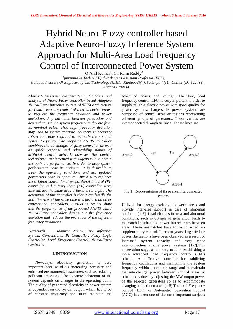
power systems. Large-scale power systems are
composed of control areas or regions representing
coherent groups of generators. These various are
interconnected through tie lines. The tie lines are
Fig 1: Representation of three area interconnected
system.
Utilized for energy exchange between areas and
provide inter-area support in case of abnormal
condition [1-5]. Load changes in area and abnormal
conditions, such as outages of generation, leads to
mismatch in scheduled power interchanges between
areas. These mismatches have to be corrected via
supplementary control. In recent years, large tie-line
power fluctuations have been observed as a result of
increased system capacity and very close
interconnection among power systems [1-2].This
observation suggests a strong need of establishing a
more advanced load frequency control (LFC)
scheme. An effective controller for stabilizing
frequency oscillations and maintaining the system
frequency within acceptable range and to maintain
the interchange power between control areas at
scheduled values by adjusting the MW output power
of the selected generators so as to accommodate
changing in load demands [4-5].The load Frequency
control (LFC) or Automatic Generation control
(AGC) has been one of the most important subjects
SSRG International Journal of Electrical and Electronics Engineering (SSRG-IJEEE) – volume 3 Issue 1 January 2016
ISSN: 2348 – 8379 www.internationaljournalssrg.org Page 18
concerning power system engineers in the last
decades. Many investigations in the area of LFC
problem have been reported and a number of control
strategies have been employed in the design of load
frequency(LF) controller in order to achieve better
dynamic performance[6-8].In recent years, fuzzy
system applications have received increasing
attention in power system operation and
control[8,9,10,11,12 ].Among the various types of
load frequency controllers, The most widely
employed is the conventional proportional
integral(PI) controller [5-6].Conventional controller
is simple for implementation but takes more time
and gives large frequency deviation. A number of
state feedback controllers based on linear optimal
control theory have been proposed to achieve better
performance [6].Fixed gain controllers are designed
at nominal operating conditions and fail to provide
best control performance over a wide range of
operating conditions. So, to keep system
performance near its optimum, it is desirable to track
the operating conditions and use updated parameters
to compute the control. Recently, fuzzy-logic control
application to power system are rapidly developing
especially power system stabilization problem [8,
10, 14, 15] as well as load frequency control
problem. The basic feature of fuzzy logic controllers
(FLCs) is that the control strategy can be simply
expressed by a set of rules which describe the
behaviour of the controller using linguistic terms.
Proper control action is then inferred from this rule
base. In additional, FLCs are relatively easy to
develop and simple to implement. The required
fuzzy rules knowledge is usually provided by a
control engineer who has analyzed extensive
mathematical modelling and development of control
algorithms for various power systems. In addition,
the design of the conventional FLC is inefficient in
the ability of self-tuning. This paper proposes a new
ANFIS based Neuro-fuzzy controller that grasps the
merits of adaptive control and Neuro-fuzzy
techniques and overcomes their drawbacks [12- 14].
With the help of MATLAB, simulations are
performed for load frequency control of two area
system by the proposed ANFIS based Neuro-Fuzzy
controller and also with conventional PI and Fuzzy
logic controller for comparison. The proposed
adaptive Neuro-Fuzzy inference system trains the
parameters of the Fuzzy logic controller and
improves the system performance. Simulation results
shows the superior performance of the proposed
Neuro-fuzzy controller in comparison with the
conventional PI controller and Fuzzy logic controller
in terms of the settling time, overshoot against
various load changes.
The main objectives of Load frequency control are
i) To maintain constant frequency throughout
the system,
ii) To preserve the tie-line power at scheduled
level irrespective of load changes in any
area
iii) To diminish Area Control Error(ACE)
iv) To minimize Peak time, Peak overshoot
and settling time.
II. MULTI AREA POWER SYSTEM
A. Load Frequency Problems:
If the system is connected to numerous
loads in a power system, then the system
frequency and speed change with the
characteristics of the governor as the load changes.
If it’s not required to maintain the frequency
constant in a system then the operator is not
required to change the setting of the generator. But
if constant frequency is required the operator can
adjust the velocity of the turbine by changing the
characteristics of the governor when required. If a
change in load is taken care by two generating
stations running parallel then the complex nature
of the system increases.
The ways of sharing the load by two machines
are as follow: 1) suppose there are two generating
stations that are connected to each other by tie line.
If the change in load is either at A or at B and the
generation of A is regulated so as to have constant
frequency then this kind of regulation is called as
Flat Frequency Regulation. 2) The other way of
sharing the load is that both A and B would
regulate their generations to maintain the
frequency constant. This is called parallel
frequency regulation. 3) The third possibility is
that the change in the frequency of a particular
area is taken care of by the generator of that area
thereby maintain the tie-line loading. This method
is known as flat tie line loading control. 4) In
Selective Frequency control each system in a
group is taken care of the load changes on its own
system and does not help the other systems, the
group for changes outside its own limits. 5) In Tie-
line Load-bias control all the power systems in the
interconnection aid in regulating frequency
regardless of where the frequency change
originates.
B. Dynamics Of The Power System
The automatic load frequency control loop
is mainly associated with the large size
generators. The main aim of the automatic load
frequency control (ALFC) can be to maintain
the desired unvarying frequency, so as to
divide loads among generators in addition to
SSRG International Journal of Electrical and Electronics Engineering (SSRG-IJEEE) – volume 3 Issue 1 January 2016
ISSN: 2348 – 8379 www.internationaljournalssrg.org Page 19
managing the exchange of tie line power in
accordance to the scheduled values.
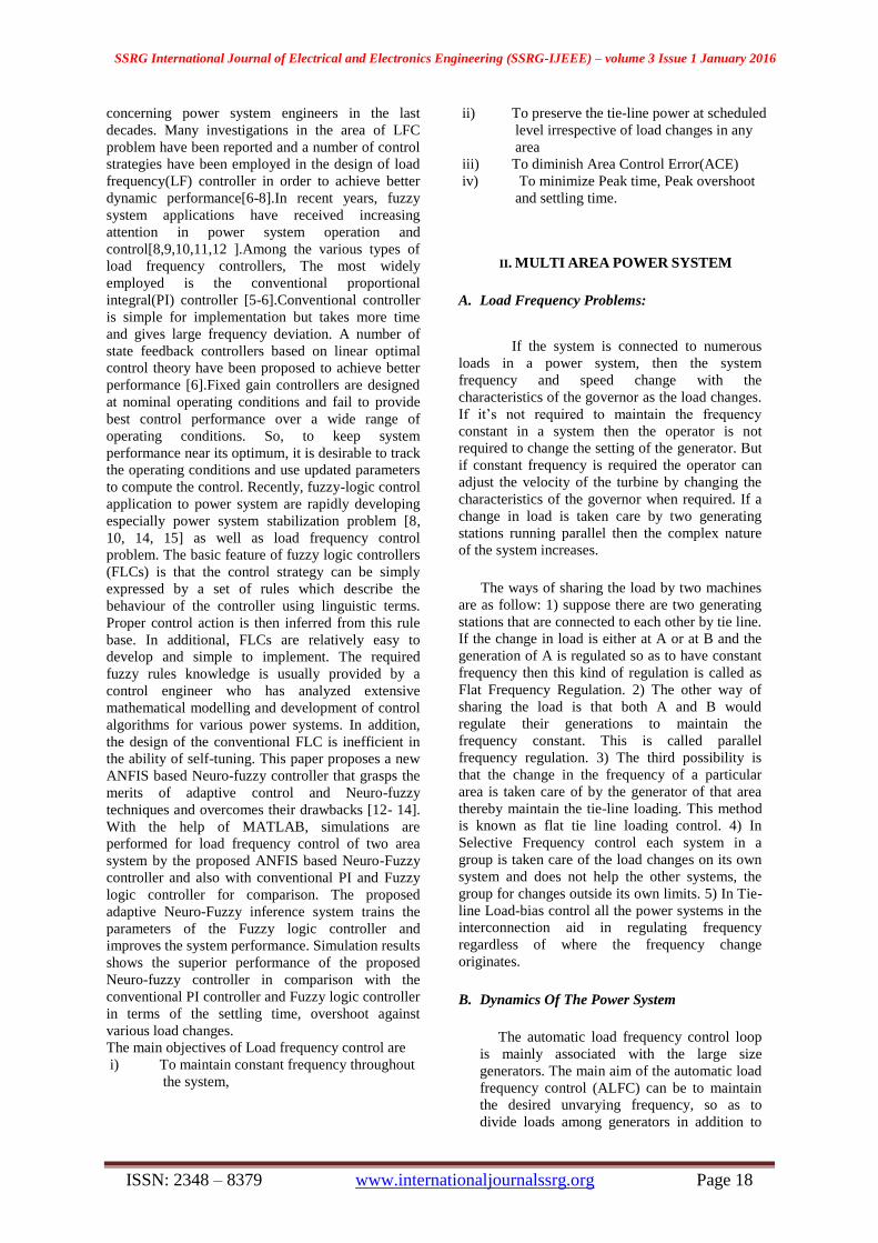
Various load frequency control loop are as given
away in the Fig. 2.1 components of the
Fig.2: Block diagram of Automatic load frequency
control
i)TURBINES : Turbines are used in power systems
for the conversion of the natural energy, like the
energy obtained from the steam or water, into
mechanical power (Pm) which can be conveniently
Supplied to the generator.
The mathematical model representation of the
turbine is,
Where ΔPV(s) = the input to the turbine
ΔPT =the output from the turbine
ii) GOVERNOR: - The governors are used in the
Power system to control the speed.
The mathematical model representation of the
turbine is,
Where Δ Pg= governor output
GENERATORS
Generators receive mechanical power from
the turbines and then convert it to electrical Power.
However our interest concerns the speed of the rotor
rather than the power Transformation
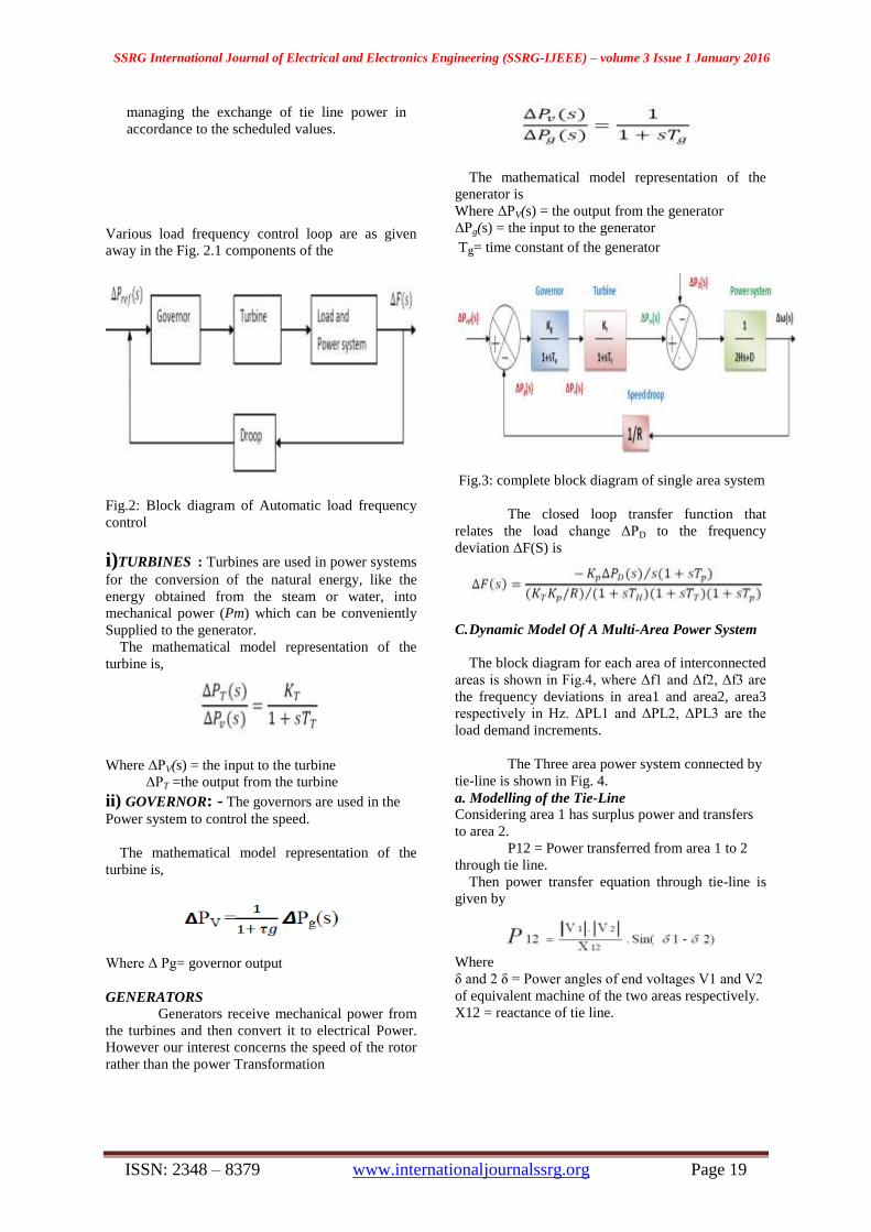
The mathematical model representation of the
generator is
Where ΔPV(s) = the output from the generator
ΔPg(s) = the input to the generator
Tg= time constant of the generator
Fig.3: complete block diagram of single area system
The closed loop transfer function that
relates the load change ΔPD to the frequency
deviation ΔF(S) is
C. Dynamic Model Of A Multi-Area Power System
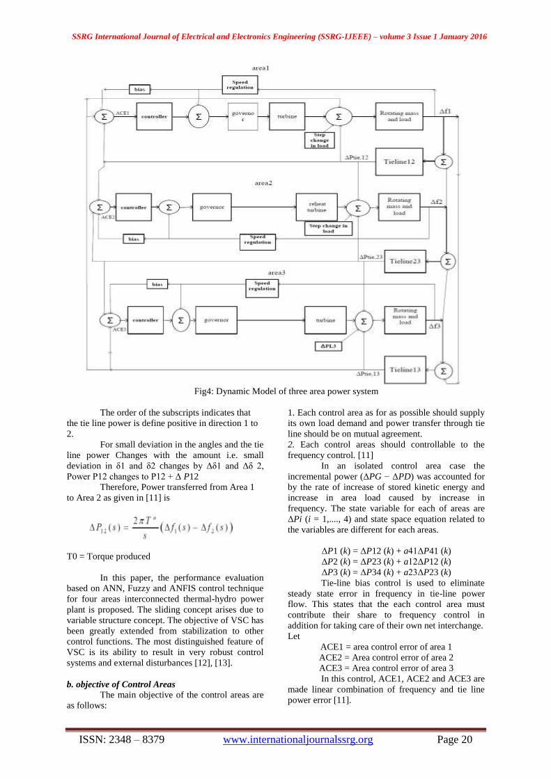
The block diagram for each area of interconnected
areas is shown in Fig.4, where Δf1 and Δf2, Δf3 are
the frequency deviations in area1 and area2, area3
respectively in Hz. ΔPL1 and ΔPL2, ΔPL3 are the
load demand increments.
The Three area power system connected by
tie-line is shown in Fig. 4.
a. Modelling of the Tie-Line
Considering area 1 has surplus power and transfers
to area 2.
P12 = Power transferred from area 1 to 2
through tie line.
Then power transfer equation through tie-line is
given by
Where
δ and 2 δ = Power angles of end voltages V1 and V2
of equivalent machine of the two areas respectively.
X12 = reactance of tie line.
SSRG International Journal of Electrical and Electronics Engineering (SSRG-IJEEE) – volume 3 Issue 1 January 2016
ISSN: 2348 – 8379 www.internationaljournalssrg.org Page 20
Fig4: Dynamic Model of three area power system
The order of the subscripts indicates that
the tie line power is define positive in direction 1 to
2.
For small deviation in the angles and the tie
line power Changes with the amount i.e. small
deviation in δ1 and δ2 changes by Δδ1 and Δδ 2,
Power P12 changes to P12 + Δ P12
Therefore, Power transferred from Area 1
to Area 2 as given in [11] is
T0 = Torque produced
In this paper, the performance evaluation
based on ANN, Fuzzy and ANFIS control technique
for four areas interconnected thermal-hydro power
plant is proposed. The sliding concept arises due to
variable structure concept. The objective of VSC has
been greatly extended from stabilization to other
control functions. The most distinguished feature of
VSC is its ability to result in very robust control
systems and external disturbances [12], [13].
b. objective of Control Areas
The main objective of the control areas are
as follows:
1. Each control area as for as possible should supply
its own load demand and power transfer through tie
line should be on mutual agreement.
2. Each control areas should controllable to the
frequency control. [11]
In an isolated control area case the
incremental power (ΔPG − ΔPD) was accounted for
by the rate of increase of stored kinetic energy and
increase in area load caused by increase in
frequency. The state variable for each of areas are
ΔPi (i = 1,...., 4) and state space equation related to
the variables are different for each areas.
ΔP1 (k) = ΔP12 (k) + a41ΔP41 (k)
ΔP2 (k) = ΔP23 (k) + a12ΔP12 (k)
ΔP3 (k) = ΔP34 (k) + a23ΔP23 (k)
Tie-line bias control is used to eliminate
steady state error in frequency in tie-line power
flow. This states that the each control area must
contribute their share to frequency control in
addition for taking care of their own net interchange.
Let
ACE1 = area control error of area 1
ACE2 = Area control error of area 2
ACE3 = Area control error of area 3
In this control, ACE1, ACE2 and ACE3 are
made linear combination of frequency and tie line
power error [11].

SSRG International Journal of Electrical and Electronics Engineering (SSRG-IJEEE) – volume 3 Issue 1 January 2016
ISSN: 2348 – 8379 www.internationaljournalssrg.org Page 21
ACE1 = Δ P12 + b1 Δ f 1
ACE2 = Δ P23 + b 2Δ f 2
ACE3 = Δ P31 + b 3Δ f 3
Where the constant b1, b2, b3 are called
area frequency bias of area 1, area 2, area 3
respectively.
Now Δ PR1 , Δ PR2 , Δ PR3and are mode
integral of ACE1, ACE2, ACE3 respectively.
III.PROPOSED SIMULINK MODEL
The implemented Simulink model worked
with the versatile nuero fuzzy interface framework is
proposed. The fuzzy logic controller which is used
to give required preparing information. The
functions are controlled by neuron process.
Fig 5: Proposed Simulink Model
The Simulink model developed with
dynamic representations. The proposed controller
can arranged to reduce the disturbances in power
system even at number of operating devices in areas.
The basic steps followed for designing the ANFIS
Controller in MATLAB/Simulink is outlined:
1. Draw the Simulink model with fuzzy controller
and Simulate it with the given rule base.
2. The first step for designing the ANFIS controller
is collecting the training data while simulating the
model with fuzzy controller.
3. The two inputs, i.e., ACE and d (ACE)/dt and the
output signal gives the training data.
4. Use anfisedit to create the ANFIS .fis file.
5. Load the training data collected in Step 2 and
generate the FIS with gbell MF’s.
6. Train the collected data with generated FIS up to a
Particular no. of Epochs.
7. Save the FIS. This FIS file is the neuro-fuzzy
enhanced
Fig 6: Proposed Anfis Control Strategy by Fuzzy
Fuzzy Logic Controllers:
Since power system dynamic characteristics are
complex and variable, conventional control methods
cannot provide desired results. Intelligent controller
can be replaced with conventional controller to get
fast and good dynamic response in load frequency
problems.
Fuzzy Logic Controller (FLC) can be more useful
in solving large scale of controlling problems with
respect to conventional controller are slower. Fuzzy
logic controller is designed to minimize fluctuation
on system outputs.
There are many studied on power system with
fuzzy logic controller. A fuzzy logic controller
consist of three section namely fuzzier, rule base and
defuzzifier as shown in fig
SSRG International Journal of Electrical and Electronics Engineering (SSRG-IJEEE) – volume 3 Issue 1 January 2016
ISSN: 2348 – 8379 www.internationaljournalssrg.org Page 22
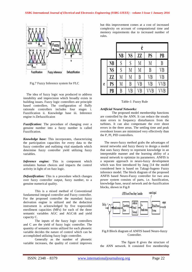
Fig.7 Fuzzy Inference system for FLC
The idea of fuzzy logic was produced to address
instability and imprecision which broadly exists in
building issues. Fuzzy logic controllers are principle
based controllers. The configuration of fluffy
rationale controllers includes four stages i.
Fuzzification ii. Knowledge base iii. Inference
engine iv.Defuzzificaion
Fuzzification: The procedure of changing over a
genuine number into a fuzzy number is called
Fuzzification.
Knowledge base: This incorporates, characterizing
the participation capacities for every data to the
fuzzy controller and outlining vital standards which
determine fuzzy controller yield utilizing fuzzy
variables.
Inference engine: This is component which
simulates human choices and impacts the control
activity in light of on fuzz logic.
Defuzzification: This is a procedure which changes
over fuzzy controller output, fuzzy number, to a
genuine numerical quality.
This is a mixed method of Conventional
fundamental integral controller and Fuzzy controller.
For the proposed controller the mamdani fuzzy
derivation engine is utilized and the deduction
instrument is acknowledged by five trapezoidal
enrollment capacities (MFs) for each of the three
semantic variables AGC and AGC/dt and yield
capacity C.
The inputs of the fuzzy logic controllers
and C are the yield of fuzzy logic controller. The
quantity of semantic terms utilized for each phonetic
variable decides the nature of control which can be
accomplished utilizing fuzzy logic controller.
Generally as the number of phonetic
variable increases, the quality of control improves
but this improvement comes at a cost of increased
complexity on account of computational time and
memory requirements due to increased number of
rules.
Table-1: Fuzzy Rule
Artificial Neural Networks:
The proposed model membership functions
are controlled by the ANN. It can reduce the steady
state errors in frequency disturbances from the
turbines. It can also compensate the over shoot
errors in the three areas. The settling time and peak
overshoot losses are minimized very effectively than
the P, PI, PID controllers.
The neuro-fuzzy method grabs the advantages of
neural networks and fuzzy theory to design a model
that uses fuzzy theory to represent knowledge in an
interpretable manner and the learning ability of a
neural network to optimize its parameters. ANFIS is
a separate approach in neuro-fuzzy development
which was first introduced by Jang [14 the model
considered here is based on Takagi-Sugeno Fuzzy
inference model. The block diagram of the proposed
ANFIS based Neuro-Fuzzy controller for two area
power system consists of parts, i.e. fuzzification,
knowledge base, neural network and de-fuzzification
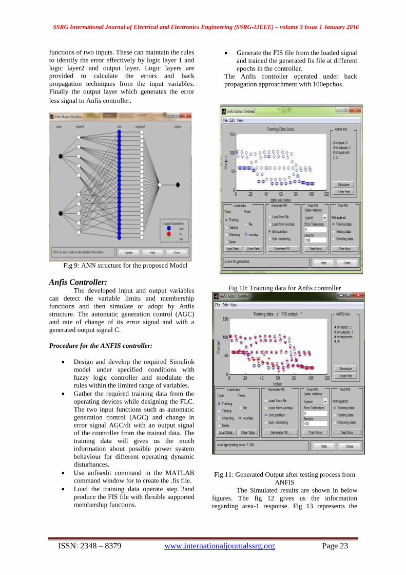
blocks, shown in Fig.8
Fig.8 Block diagram of ANFIS based Neuro-fuzzy
Controller.
The figure 8 gives the structure of
the ANN network. It consisted five membership
SSRG International Journal of Electrical and Electronics Engineering (SSRG-IJEEE) – volume 3 Issue 1 January 2016
ISSN: 2348 – 8379 www.internationaljournalssrg.org Page 23
functions of two inputs. These can maintain the rules
to identify the error effectively by logic layer 1 and
logic layer2 and output layer. Logic layers are
provided to calculate the errors and back
propagation techniques from the input variables.
Finally the output layer which generates the error
less signal to Anfis controller.
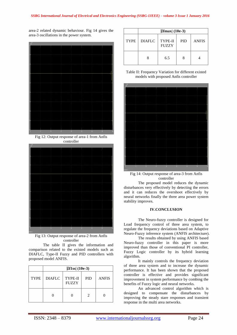
Fig 9: ANN structure for the proposed Model
Anfis Controller: The developed input and output variables
can detect the variable limits and membership
functions and then simulate or adopt by Anfis
structure. The automatic generation control (AGC)
and rate of change of its error signal and with a
generated output signal C.
Procedure for the ANFIS controller:
Design and develop the required Simulink
model under specified conditions with
fuzzy logic controller and modulate the
rules within the limited range of variables.
Gather the required training data from the
operating devices while designing the FLC.
The two input functions such as automatic
generation control (AGC) and change in
error signal AGC/dt with an output signal
of the controller from the trained data. The
training data will gives us the much
information about possible power system
behaviour for different operating dynamic
disturbances.
Use anfisedit command in the MATLAB
command window for to create the .fis file.
Load the training data operate step 2and
produce the FIS file with flexible supported
membership functions.
Generate the FIS file from the loaded signal
and trained the generated fis file at different
epochs in the controller.
The Anfis controller operated under back
propagation approachment with 100epchos.
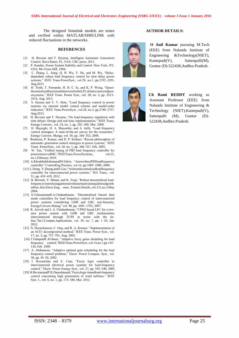
Fig 10: Training data for Anfis controller
Fig 11: Generated Output after testing process from
ANFIS
The Simulated results are shown in below
figures. The fig 12 gives us the information
regarding area-1 response. Fig 13 represents the
SSRG International Journal of Electrical and Electronics Engineering (SSRG-IJEEE) – volume 3 Issue 1 January 2016
ISSN: 2348 – 8379 www.internationaljournalssrg.org Page 24
area-2 related dynamic behaviour. Fig 14 gives the
area-3 oscillations in the power system.
Fig 12: Output response of area-1 from Anfis
controller
Fig 13: Output response of area-2 from Anfis
controller
The table II gives the information and
comparison related to the existed models such as
DIAFLC, Type-II Fuzzy and PID controllers with
proposed model ANFIS.
|Δf1ss| (10e-3)
TYPE
DIAFLC
TYPE-II
FUZZY
PID
ANFIS
0
0
2
0
|Δfmax| (10e-3)
TYPE
DIAFLC
TYPE-II
FUZZY
PID
ANFIS
8
6.5
8
4
Table II: Frequency Variation for different existed
models with proposed Anfis controller
Fig 14: Output response of area-3 from Anfis
controller
The proposed model reduces the dynamic
disturbances very effectively by detecting the errors
and it can reduces the overshoot effectively by
neural networks finally the three area power system
stability improves.
IV.CONCLUSION
The Neuro-fuzzy controller is designed for
Load frequency control of three area system, to
regulate the frequency deviations based on Adaptive
Neuro-Fuzzy inference system (ANFIS architecture).
The results obtained by using ANFIS based
Neuro-fuzzy controller in this paper is more
improved than those of conventional PI controller,
Fuzzy Logic controller by its hybrid learning
algorithm.
It mainly controls the frequency deviation
of three area system and to increase the dynamic
performance. It has been shown that the proposed
controller is effective and provides significant
improvement in system performance by combing the
benefits of Fuzzy logic and neural networks.
An advanced control algorithm which is
designed to compensate the disturbances by
improving the steady stare responses and transient
response in the multi area networks.
SSRG International Journal of Electrical and Electronics Engineering (SSRG-IJEEE) – volume 3 Issue 1 January 2016
ISSN: 2348 – 8379 www.internationaljournalssrg.org Page 25
The designed Simulink models are testes
and verified within MATLAB/SIMULINK with
reduced fluctuations in the networks.
REFERENCES
[1] H. Bevrani and T. Hiyama, Intelligent Automatic Generation
Control. Boca Raton, FL, USA: CRC press, 2011. [2] P. Kundur, Power System Stability and Control. New York, NY,
USA: Mc-Graw Hill, 1994.
[3] C. Zhang, L. Jiang, Q. H. Wu, Y. He, and M. Wu, ―Delay-dependent robust load frequency control for time delay power
systems,‖ IEEE Trans.PowerSyst., vol.28, no.3, pp.2192–2201,
Aug.2013. [4] H. Trinh, T. Fernando, H. H. C. Iu, and K. P. Wong, ―Quasi-
decentralizedfunctionalobserversfortheLFCofinterconnectedpow
ersystems,‖ IEEE Trans. Power Syst., vol. 28, no. 3, pp. 3513–3514, Aug. 2013.
[5] S. Saxena and Y. V. Hote, ―Load frequency control in power
systems via internal model control scheme and model-order reduction,‖ IEEE Trans.PowerSyst., vol.28, no.3, pp.2749–2757,
Aug.2013.
[6] H. Bevrani and T. Hiyama, ―On load-frequency regulation with time delays: Design and real-time implementation,‖ IEEE Trans.
Energy Convers., vol. 24, no. 1, pp. 292–300, Mar. 2009. [7] H. Shayeghi, H. A. Shayanfar, and A. Jalili, ―Load frequency
control strategies: A state-of-the-art survey for the researcher,‖
Energy Convers. Manga. vol. 50, pp. 344–353, 2009. [8] Ibraheem, P. Kumar, and D. P. Kothari, ―Recent philosophies of
automatic generation control strategies in power systems,‖ IEEE
Trans. PowerSyst., vol. 20, no. 1, pp. 346–357, Feb. 2005. [9] W. Tan, ―Unified tuning of PID load frequency controller for
powerstemsviaIMC,‖IEEETrans.PowerSystems, vol.25,
no.1,February 2010. [10] A.KhodabakhshianandM.Edrisi, ―AnewrobustPIDloadfrequency
controller‖ ControlEng.Practice, vol.16, pp.1069–1080, 2008.
[11] L.Dong, Y.Zhang,andZ.Gao,―Arobustdecentralizedloadfrequency controller for interconnected power systems,‖ ISA Trans., vol.
51, pp. 410–419, 2012.
[12] H. Bevrani, Y. Mitani, and K. Tsuji, ―Robust decentralised load-frequencycontrolusinganiterativelinearmatrixinequalitiesalgorith
mProc.Inst.Electr.Eng.—ener.,Transm.Distrib.,vol.151,no.3,May
2004. [13] S.VelusamiandI.A.Chidambaram, ―Decentralized biased dual
mode controllers for load frequency control of interconnected
power systems considering GDB and GRC non-linearity, EnergyConvers.Manag‖ vol. 48, pp. 1691–1702, 2007.
[14] R. Arivoli and I. A. Chidambaram, ―CPSO based LFC for a two-
area power system with GDB and GRC nonlinearities interconnected through TCPS in series with the tie-
line,‖Int.J.Comput.Applications, vol. 38, no. 7, pp. 1–10, Jan.
2012. [15] N. Hoonchareon, C. Ong, and R. A. Kramer, ―Implementation of
an ACE1 decomposition method,‖ IEEE Trans. Power Syst., vol.
17, no. 3, pp. 757–761, Aug. 2002. [16] J.TalaqandF.Al-Basri, ―Adaptive fuzzy gains cheduling for load
frequency control,‖IEEETrans.PowerSyst.,vol.14,no.1,pp.145–
150, Feb. 1999. [17] A. Abdennour, ―Adaptive optimal gain scheduling for the load
frequency control problem,‖ Electr. Power Compon. Syst., vol.
30, pp. 45–56, 2002. [18] I. Kocaarslan and E. Cam, ―Fuzzy logic controller in
interconnected electrical power systems for load-frequency
control,‖ Electr. Power Energy Syst., vol. 27, pp. 542–549, 2005. [19] H.BevraniandP.R.Daneshmand,―Fuzzylogic-basedload-frequency
control concerning high penetration of wind turbines,‖ IEEE
Syst. J., vol. 6, no. 1, pp. 173–180, Mar. 2012.
AUTHOR DETAILS:
O Anil Kumar pursuing M.Tech
(EEE) from Nalanda Institute of
Engineering &Technology(NIET),
Kantepudi(V), Sattenpalli(M),
Guntur (D)-522438,Andhra Pradesh.
C Ch Rami REDDY working as
Assistant Professor (EEE) from
Nalanda Institute of Engineering &
Technology (NIET),Kantepudi(V),
Sattenpalli (M), Guntur (D)-
522438,Andhra Pradesh.


![Design features and research on the neuro-like learning ... · systems based on neuro-fuzzy logic: - an adaptive neuro-fuzzy inference system (ANFIS) [15]; - an adaptive neurofuzzy](https://img.pdfslide.net/doc/110x75/605ac52cb6bd5c4a7f031940/design-features-and-research-on-the-neuro-like-learning-systems-based-on-neuro-fuzzy.jpg)