Embed Size (px)
Citation preview
Hybrid noise control in a duct using a lightmicro-perforated plate
X. N. Wang, Y. S. Choy, and L. Chenga)
Department of Mechanical Engineering, The Hong Kong Polytechnic University, Hung Hom, Kowloon, HongKong Special Administrative Region, China
(Received 26 June 2012; revised 25 September 2012; accepted 1 October 2012)
A plate silencer consists of an expansion chamber with two side-branch cavities covered by
light but extremely stiff plates. It works effectively with a wide stopband from low-to-medium
frequencies only if the plate is extremely stiff, to ensure a strong reflection of acoustic wave to
the upstream in the duct. However, a plate with a slightly weak bending stiffness will result in non-
uniform transmission loss (TL) spectra with narrowed stopband. In this study, a hybrid silencer is
proposed by introducing micro-perforations into the plate to elicit the sound absorption in order
to compensate for the deficiency in the passband caused by the insufficient sound reflection in a
certain frequency range due to weaker plate stiffness. A theoretical model, capable of dealing with
the strong coupling between the vibrating micro-perforated plate and sound fields inside the cavity
and the duct, is developed. Through proper balancing between the sound absorption and reflection,
the proposed hybrid silencer provides a more flattened and uniform TL and a widened stopband
by more than 20% while relaxing the harsh requirement on the bending stiffness of the plate.
Theoretical predictions are validated by experimental data, with phenomenon explained through
numerical analyses. VC 2012 Acoustical Society of America. [http://dx.doi.org/10.1121/1.4763550]
PACS number(s): 43.50.Gf, 43.55.Ev [NX] Pages: 3778–3787
I. INTRODUCTION
Abatement of low frequency noise has always been a
challenging topic. Most traditional methods such as porous
duct lining and expansion chamber still suffer from serious
drawbacks. Despite its wide use in air conditioning and ven-
tilation systems, duct lining with a porous sound absorbing
material fails to perform well at low frequencies because of
its high characteristic impedance. Meanwhile fibrous materi-
als cause the environmental concerns such as accumulation
of dusts in the pores of the porous material and bacteria
breeding. Expansion chambers usually occupy a relatively
large volume in order to cope with low frequency noise, at
the expense of creating significant pressure loss in a flow
duct, and loosing efficiency at multiple frequencies at which
the chamber length equals half a wavelength.
Aiming at a compact, broadband, and relatively low fre-
quency noise control device, a continuous effort has been
made to develop silencers comprising an expansion chamber
with two side-branch cavities covered with plates.1,2 The
working principle of such a device, referred to as a plate si-
lencer, makes use of a sound reflection mechanism inside a
duct. Upon proper tuning of the plate parameters, the plate,
flush-mounted with the inner duct wall, reflects the sound to
the upstream side, creating favorable interference with the
incoming sound. While the promises of this new technique
were well demonstrated in our previous work, there still exist
some serious limitations hampering its application, which
are mainly twofold: (1) The plate should have a very high
bending stiffness and a very low mass ratio. For example, to
ensure a reasonable level of structural response induced by
an acoustic incident wave, the mass ratio of plate to air
should be about unity. Meanwhile the dimensionless bending
stiffness should be about 0.07, which is equivalent to an alu-
minum plate 1.4 mm thick with the same width. However, a
1.4 mm thick aluminum plate has a mass ratio to air of
approximately 25.3, which far exceeds the desirable mass ra-
tio range. Therefore, a plate silencer purely based on sound
reflection puts a very harsh requirement which can hardly be
satisfied by conventional materials, not even the specially
designed sandwich plates2 or the carbon fiber (CF) rein-
forced composite plates3 in the most rigorous sense. Failing
to do so results in a significant reduction in both the trans-
mission loss (TL) level and the stopband. (2) The perform-
ance of the silencer is highly non-uniform across the
frequency range, as demonstrated by the drastic fluctuation
as well as the existence of troughs (passband) in the medium
frequency range of the TL curve. This not only directly con-
tributes to narrowing the stopband of the device but also lim-
its the use of the device for broadband noise control.
In order to achieve a wider stopband, a hybrid silencer
is proposed in this work by introducing micro-perforations
into a very light and moderately stiff plate. The purpose of
the micro-perforations is to add sound absorptions to com-
pensate for the deficiency in the passband caused by the
insufficient sound reflection due to the plate with a weaker
strength to mass ratio. The proposed hybrid silencer differs
from the existing plate silencer in that sound reflection and
absorption take a dominant effect at different frequency
ranges to provide a more flattened/uniformed TL curve. That
is the reason why this silencer is referred to as “hybrid.” By
the same token, the harsh requirement in terms of high
a)Author to whom correspondence should be addressed. Electronic mail:
3778 J. Acoust. Soc. Am. 132 (6), December 2012 0001-4966/2012/132(6)/3778/10/$30.00 VC 2012 Acoustical Society of America
Redistribution subject to ASA license or copyright; see http://acousticalsociety.org/content/terms. Download to IP: 158.132.161.103 On: Fri, 27 Dec 2013 09:57:40
bending stiffness is relaxed along with an enlargement of the
stopband, as will be shown later in the paper. The proposed
hybrid silencer also differs from the traditional micro-
perforated plate (MPP) absorber design, which is proposed by
Maa4 and extensively used in the different areas such as room
acoustics,5–7 barrier design,8 and duct.9–12 A typical MPP
absorber takes the form of an MPP in front of a backing cavity
that can achieve Helmholtz sound absorption.13–15 In the past,
the use of a micro-perforated tube or plate in a single expan-
sion chamber9,10 or multiple chamber11 was also investigated,
entirely for sound absorption with an acoustically rigid micro-
perforated structure. Up to now, most existing studies in such
studies focused on the function of the MPP device itself with-
out considering the vibration of the plate and its vibroacoustic
coupling with the sound field in the duct.
The proposed hybrid silencer consists of two light and
moderately stiff plates with micro-perforations, covering
two rectangular cavities. With the grazing in-coming waves
passing over the surface of the plate, the plate is excited to
vibrate, which in turn radiates sound both upstream and
downstream. Meanwhile, the radiated sound pressure in both
the duct and inside the cavity interacts with the plate vibra-
tion, forming a strongly coupled vibroacoustic system. With
the micro-perforations, part of the acoustic energy is
absorbed and by the same token, the response of the plate, as
well as its sound radiation, is expected to be affected. The
balance between the compromised sound reflection and
enhanced sound absorption is the key to achieve a flattened
and widened stopband in the TL curve, conducive to broad-
band noise control.
The objectives of this study are (1) to establish a theo-
retical vibroacoustic model, which takes into account the full
coupling between the MPP and the sound field in a duct and
cavity; (2) to understand the underlying physics related to
the sound reflection and absorption due to the use of micro-
perforation as well as its impact on the silencer performance;
and (3) to propose guidelines toward the optimal design of
an effective hybrid silencer.
In what follows, Sec. II outlines the theoretical model
for the plate silencer with micro-perforations. Modal expan-
sion is used to solve the fully coupled system among the
plate, the cavity, the duct and the micro-perforated orifices.
A performance analysis will be carried out in Sec. III. The
response of the plate, interaction between sound absorption,
and sound radiation from the plate will be analyzed. An opti-
mization process is to be conducted in order to search for
optimal physical parameters such as properties of perfora-
tions and structural properties of the plate so that the best
performance can be obtained. An experimental validation
will be given in Sec. IV.
II. FORMULATION
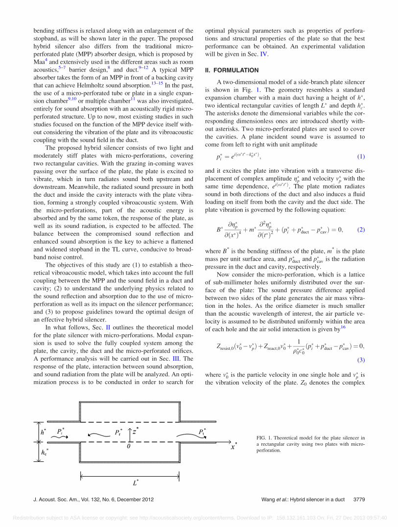
A two-dimensional model of a side-branch plate silencer
is shown in Fig. 1. The geometry resembles a standard
expansion chamber with a main duct having a height of h�,two identical rectangular cavities of length L� and depth h�c .
The asterisks denote the dimensional variables while the cor-
responding dimensionless ones are introduced shortly with-
out asterisks. Two micro-perforated plates are used to cover
the cavities. A plane incident sound wave is assumed to
come from left to right with unit amplitude
p�i ¼ eiðx�t��k�0x�Þ; (1)
and it excites the plate into vibration with a transverse dis-
placement of complex amplitude g�p and velocity v�p with the
same time dependence, eiðx�t�Þ. The plate motion radiates
sound in both directions of the duct and also induces a fluid
loading on itself from both the cavity and the duct side. The
plate vibration is governed by the following equation:
B�@g�p@ðx�Þ4
þ m�@2g�p@ðt�Þ2
þ ðp�i þ p�duct � p�cavÞ ¼ 0; (2)
where B* is the bending stiffness of the plate, m* is the plate
mass per unit surface area, and p�duct and p�cav is the radiation
pressure in the duct and cavity, respectively.
Now consider the micro-perforation, which is a lattice
of sub-millimeter holes uniformly distributed over the sur-
face of the plate: The sound pressure difference applied
between two sides of the plate generates the air mass vibra-
tion in the holes. As the orifice diameter is much smaller
than the acoustic wavelength of interest, the air particle ve-
locity is assumed to be distributed uniformly within the area
of each hole and the air solid interaction is given by16
Zresist;0ðv�0� v�pÞþZreact;0v�0þ1
q�0c�0ðp�i þ p�duct� p�cavÞ ¼ 0;
(3)
where v�0 is the particle velocity in one single hole and v�p is
the vibration velocity of the plate. Z0 denotes the complex
FIG. 1. Theoretical model for the plate silencer in
a rectangular cavity using two plates with micro-
perforation.
J. Acoust. Soc. Am., Vol. 132, No. 6, December 2012 Wang et al.: Hybrid silencer in a duct 3779
Redistribution subject to ASA license or copyright; see http://acousticalsociety.org/content/terms. Download to IP: 158.132.161.103 On: Fri, 27 Dec 2013 09:57:40
acoustic impedance of the hole normalized by the character-
istic impedance of the air q�0c�0. Zresist;0 and Zreact;0 are the re-
sistant and reactant parts of Z0, respectively, which are
proposed by Maa,4
Z0 ¼ Zresist;0 þ Zreact;0
¼ 32l�s�
q�0c�0ðd�Þ2
1þ K2
32
� �0:5
þffiffiffi2p
Kd�
32s�
" #
þ ix�s�
c�01þ 1þ K2
32
� ��0:5
þ 0:85d�
s�
" #; (4)
where s� is the thickness of the plate, d� is the diameter
of the hole, l� is the coefficient of viscosity, and
K ¼ d�=2ffiffiffiffiffiffiffiffiffiffiffiffiffiffiffiffiffiq�0x
�=l�p
.
All the dimensional variables used are nondimensional-
ized by three quantities: Air density q�0, speed of sound in
free space c�0, and duct height h� as
x¼ x�
h�; z¼ z�
h�; hc ¼
h�ch�; L¼ L�
h�; gp ¼
g�ph�;
f ¼ f �h�
c�0; m¼ m�
q�0h�; B¼ B�
q�0ðh�Þ3ðc�0Þ
2;
p¼ p�
q�0ðc�0Þ2; d¼ d�
h�; s¼ s�
h�; l¼ l�
q�0c�0h�: (5)
Assuming the plate is in harmonic motion vp ¼ @gp=@t¼ ixgp, Eq. (2) can be written as
B
ix@4vp
@x4þ mixvp þ ðpi þ pduct � pcavÞ ¼ 0: (6)
Equation (3) turns into
Zresist;0ðv0 � vpÞ þ Zreact;0v0 þ pi þ pduct � pcav ¼ 0: (7)
An average air velocity �v0 is obtained by averaging the dis-
crete air particle velocity over each orifice across the adja-
cent imperforated region of the plate as
�v0 ¼ v0r; (8)
where r is the perforation ratio of the plate. The dynamics of
the plate described in Eqs. (6) and (7) can be solved by the
standard Galerkin procedure in which vpðxÞ is expanded as a
series of in vacuo modes ujðnÞ of the clamped-clamped
plates with modal amplitude Vp;j
vpðxÞ ¼X1j¼1
Vp;jujðnÞ; n ¼ x=Lþ 1=2; (9)
where
ujðnÞ ¼ A1;jekjn þ A2;je
�kjn þ A3;jsinðkjnÞ
þ A4;jcosðkjnÞ; (10)
with
A1;j¼1
2ð1� ejÞ; A2;j¼
1
2ð1þ ejÞ; A3;j¼ ej; A4;j¼�1;
(11)
ej ¼coshðkjÞ � cosðkjÞsinhðkjÞ � sinðkjÞ
; cosðkjÞ � coshðkjÞ ¼ 1: (12)
So �v0 is also expanded over the same series ujðnÞ as
�v0ðxÞ ¼X1j¼1
�V0;jujðnÞ: (13)
So v0ðxÞ ¼P1
j¼1 V0;jujðnÞ with V0;j ¼ �V 0;j=r.
Therefore, Eqs. (6) and (7) become
B
ix
bj
L
� �4
þmix
( )Vp;jþ
ð1
0
ðpiþpduct�pcavÞujðnÞdn¼0;
(14)
Zresist;0ðV0;j � Vp;jÞ þ Zreact;0V0;j
þð1
0
ðpi þ pduct � pcavÞujðnÞdn ¼ 0; (15)
respectively.
Given the average velocity distribution for the whole
plate with micro-perforations, �vðxÞ, which is defined as
�vðxÞ ¼ ð1� rÞvpðxÞ þ �v0ðxÞ, the radiated pressure pduct can
be calculated as17
pductðx; zÞ ¼L
2
X1n¼0
cn/nðzÞ
�ð1
0
�vðx0Þ/nðz0Þ½Hðx� x0Þe�iknðx�x0Þ
þHðx0 � xÞeþiknðx�x0Þ�dn0; (16)
with
cn ¼iffiffiffiffiffiffiffiffiffiffiffiffiffiffiffiffiffiffiffiffiffiffiffiffiffi
ðnp=xÞ2 � 1
q ; kn ¼xcn;
/nðzÞ ¼ffiffiffiffiffiffiffiffiffiffiffiffiffiffiffi2� d0n
pcosðnpzÞ; (17)
where H(x) is the Heaviside function, d0n is the Kronecker
delta, cn, kn, /n are, respectively, modal phase speed, modal
wave number, and the modal velocity potential. The source
is specified as a plate vibration at z0 ¼ 0, x0�[�L/2, L/2].
Assuming that the radiation pressure caused by the jthmodal vibration of unit amplitude uj is pduct;j, the duct modal
impedance is then defined as
Zduct;jl ¼ð1
0
pduct;jðx; 0ÞulðnÞdn: (18)
The sound pressure inside the cavity pcav, can be expressed
in terms of acoustic modes of rigid-walled cavity with a light
damping18
pcavðx; zÞ ¼Xr;s
�ixwrsðx; zÞLhcðj2
rs � k20 þ 2ifrsjrsk0Þ
�ð1
0
�vðx0; 0Þwrsðx0; 0Þdn0; (19)
3780 J. Acoust. Soc. Am., Vol. 132, No. 6, December 2012 Wang et al.: Hybrid silencer in a duct
Redistribution subject to ASA license or copyright; see http://acousticalsociety.org/content/terms. Download to IP: 158.132.161.103 On: Fri, 27 Dec 2013 09:57:40

where frs is the damping ratio of the (r,s)th acoustic mode
wrsðx; zÞ, and jrs is the corresponding acoustic wave number
of the acoustic mode wrsðx; zÞ, with wrsðx; zÞ and jrs given as
wrsðx; zÞ ¼ffiffiffiffiffiffiffiffiffiffiffiffiffiffiffiffiffiffiffiffiffiffiffiffiffiffiffiffiffiffiffiffiffiffiffiffið2� d0rÞð2� d0sÞ
pcos
rpx
L
� �cos
spz
hc
� �;
(20)
j2rs ¼
rpL
� �2
þ sphc
� �2
: (21)
Similarly, the cavity modal impedance is given as
Zcav;jl ¼ �ð1
0
pcav;jðx; 0ÞulðnÞdn: (22)
Therefore, Eqs. (14) and (15) can be cast into a set of linear
equations in terms of modal vibration in j mode as
LjVp;j þ ðZduct;jl � Zcav;jlÞ½ð1� rÞVp;j þ rV0;j� ¼ �Ij;
(23)
Zresist;0ðV0;j � Vp;jÞ þ Zreact;0V0;j
þ ðZduct;jl � Zcav;jlÞ½ð1� rÞVp;j þ rV0;j� ¼ �Ij; (24)
where Lj ¼ fðB=ixÞðbj=LÞ4 þ mixg, and Ij is the modal
coefficient of incident waves which is defined as
Ij ¼ð1
0
piujðnÞdn: (25)
V0;j and Vp;j can be solved through matrix inversion.
The total sound pressure transmitted to the downstream
is found by adding the incident wave pi to the far-field radia-
tion wave pduct, which can be found with the help of Eq. (16)
by taking only the plane wave mode with n ¼ 0 for x > L=2
pt ¼ pductjn¼0;x!þ1 þ pi: (26)
Similarly
pr ¼ pductjn¼0;x!�1: (27)
Hence, for an incident wave of unit amplitude, the TL
of the silencer can be calculated as
TL ¼ �20 log10
jptjjpij
: (28)
The coefficients of sound power reflected and absorbed are
calculated, respectively, by
b ¼���� pr
pi
����2
; a ¼ 1� b����� pt
pi
����2
; (29)
where pr is given by
pr ¼1
2
ðL=2
�L=2
�vðx0Þe�ik0x0dx0 ¼X1j¼1
�VjRj; (30)
with
Rj ¼ðL=2
�L=2
ujðn0Þe�ik0x0dx0: (31)
Rj is the complex amplitude of the reflected sound by the
induced vibration of the jth mode with unit amplitude, and�VjRj is defined as the modal reflection which evaluates the
reflection ability for each mode.
III. NUMERICAL RESULTS AND ANALYSES
A plate silencer with micro-perforations involves many
variables. A performance study is first carried out with most
variables fixed such that the length of the plate (L¼ 5), the
cavity depth (hc ¼ 1), the height of the duct (h¼ 1), and
the mass ratio of the plate (m ¼ 1). The bending stiffness of
the plate is a very influential parameter which is varied while
studying the effect of the micro-perforation properties such
as the diameter of the holes, the perforation ratio, and the
thickness of the plate. The performance of the plate-silencer
is evaluated by the logarithmic width of its stopband, defined
as the frequency range in which TL is everywhere equal
to or greater than a suitable criterion level (TLcr). Expressed
symbolically, f 2 ½f1; f2� in which TL � TLcr and TLcr
¼ 10 dB in the present study. A cost function is set as the ra-
tio of the band limits f2=f1 in the design optimization.
In order to ensure the accuracy of the calculation, the
duct, cavity, and plate modes are truncated to 50, 50, and 25,
respectively. A further increase in the number of modes does
not make a noticeable improvement in the calculation results
within the frequency range of interest of the present work.
A. Perforation effect
The effect of the micro-perforation on the TL is first
shown before detailed analyses are presented Secs. III B–III E.
Figure 2 compares the TL of the plate silencer with and
without micro-perforations under three configurations. The
TL curve of a plate silencer without perforation with
B¼ 0.07, previously determined as the optimal bending stiff-
ness for the plate silencer without any perforations, is shown
as the dotted line. Three peaks are observed, which have
been shown to be caused by the strong sound reflection from
the plate due to the dominance of the first two modes of the
plate. The stopband begins from f1 ¼ 0:044 and ends at
f2 ¼ 0:124, corresponding to f2=f1 ¼ 2:81. Note that the
bending stiffness required is very high. Reducing B by about
20% down to 0.057, the trough between the second and
third peak in the TL curve drastically drops down, resulting
in a TL of less than 10 dB so that the overall stopband is sig-
nificantly decreased to f2=f1 ¼ 2:21 (dashed line). Keeping
the same bending stiffness at B ¼ 0:057, perforations
with r ¼ 0:7% and nondimensional diameter d¼ 0.007
(dimensional diameter d*¼ 0.7 mm), are then added to the
plate. It can be seen that the micro-perforation effect can lift
up the trough point between the second and third peak so
that a more flattened TL curve is obtained. Meanwhile, com-
pared to TL of B¼ 0.07, while basically keeping the same f1,
the third peak on the TL curve is moved to a higher fre-
quency so that the stopband ends at a much higher frequency
J. Acoust. Soc. Am., Vol. 132, No. 6, December 2012 Wang et al.: Hybrid silencer in a duct 3781
Redistribution subject to ASA license or copyright; see http://acousticalsociety.org/content/terms. Download to IP: 158.132.161.103 On: Fri, 27 Dec 2013 09:57:40
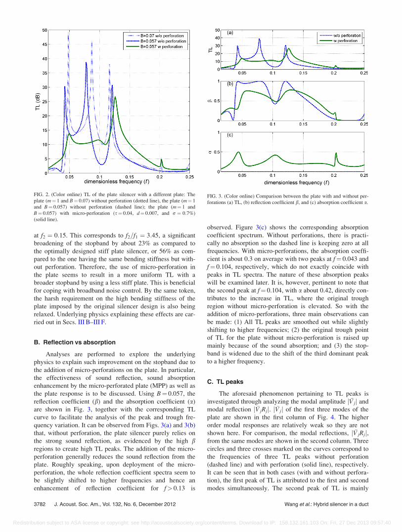
at f2 ¼ 0:15. This corresponds to f2=f1 ¼ 3:45, a significant
broadening of the stopband by about 23% as compared to
the optimally designed stiff plate silencer, or 56% as com-
pared to the one having the same bending stiffness but with-
out perforation. Therefore, the use of micro-perforation in
the plate seems to result in a more uniform TL with a
broader stopband by using a less stiff plate. This is beneficial
for coping with broadband noise control. By the same token,
the harsh requirement on the high bending stiffness of the
plate imposed by the original silencer design is also being
relaxed. Underlying physics explaining these effects are car-
ried out in Secs. III B–III F.
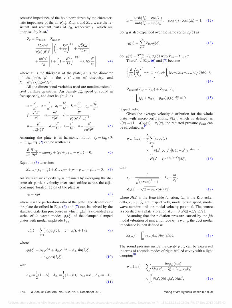
B. Reflection vs absorption
Analyses are performed to explore the underlying
physics to explain such improvement on the stopband due to
the addition of micro-perforations on the plate. In particular,
the effectiveness of sound reflection, sound absorption
enhancement by the micro-perforated plate (MPP) as well as
the plate response is to be discussed. Using B¼ 0.057, the
reflection coefficient (b) and the absorption coefficient (a)
are shown in Fig. 3, together with the corresponding TL
curve to facilitate the analysis of the peak and trough fre-
quency variation. It can be observed from Figs. 3(a) and 3(b)
that, without perforation, the plate silencer purely relies on
the strong sound reflection, as evidenced by the high bregions to create high TL peaks. The addition of the micro-
perforation generally reduces the sound reflection from the
plate. Roughly speaking, upon deployment of the micro-
perforation, the whole reflection coefficient spectra seem to
be slightly shifted to higher frequencies and hence an
enhancement of reflection coefficient for f> 0.13 is
observed. Figure 3(c) shows the corresponding absorption
coefficient spectrum. Without perforations, there is practi-
cally no absorption so the dashed line is keeping zero at all
frequencies. With micro-perforations, the absorption coeffi-
cient is about 0.3 on average with two peaks at f¼ 0.043 and
f¼ 0.104, respectively, which do not exactly coincide with
peaks in TL spectra. The nature of these absorption peaks
will be examined later. It is, however, pertinent to note that
the second peak at f¼ 0.104, with a about 0.42, directly con-
tributes to the increase in TL, where the original trough
region without micro-perforation is elevated. So with the
addition of micro-perforations, three main observations can
be made: (1) All TL peaks are smoothed out while slightly
shifting to higher frequencies; (2) the original trough point
of TL for the plate without micro-perforation is raised up
mainly because of the sound absorption; and (3) the stop-
band is widened due to the shift of the third dominant peak
to a higher frequency.
C. TL peaks
The aforesaid phenomenon pertaining to TL peaks is
investigated through analyzing the modal amplitude j �Vjj and
modal reflection j �VjRjj. j �Vjj of the first three modes of the
plate are shown in the first column of Fig. 4. The higher
order modal responses are relatively weak so they are not
shown here. For comparison, the modal reflections, j �VjRjj,from the same modes are shown in the second column. Three
circles and three crosses marked on the curves correspond to
the frequencies of three TL peaks without perforation
(dashed line) and with perforation (solid line), respectively.
It can be seen that in both cases (with and without perfora-
tion), the first peak of TL is attributed to the first and second
modes simultaneously. The second peak of TL is mainly
FIG. 2. (Color online) TL of the plate silencer with a different plate: The
plate (m¼ 1 and B¼ 0.07) without perforation (dotted line), the plate (m¼ 1
and B¼ 0.057) without perforation (dashed line); the plate (m¼ 1 and
B¼ 0.057) with micro-perforation (s¼ 0.04, d¼ 0.007, and r ¼ 0:7%)
(solid line).
FIG. 3. (Color online) Comparison between the plate with and without per-
forations (a) TL, (b) reflection coefficient b, and (c) absorption coefficient a.
3782 J. Acoust. Soc. Am., Vol. 132, No. 6, December 2012 Wang et al.: Hybrid silencer in a duct
Redistribution subject to ASA license or copyright; see http://acousticalsociety.org/content/terms. Download to IP: 158.132.161.103 On: Fri, 27 Dec 2013 09:57:40

dominated by the first mode while the third peak of TL is
due to the second modal contribution. For the micro-
perforated plate, the first peak of TL is reduced as a result of
a reduction in both j �V1j and j �V2j, as shown in Figs. 1(a) and
1(b). This is due to the fact that the introduction of the
micro-perforation brings about a certain degree of pressure
balance across the perforated panel through the holes so that
the resulting excitation on the plate is reduced, leading to an
ultimate reduction in the response of the plate. A similar
trend can also be observed from the variation of j �V1R1j and
j �V2R2j, shown in Figs. 4(2a) and 4(2b), respectively. Com-
pared to the plate without micro-perforation, the sound
reflection from the perforated plate is also reduced. It should
be noted that the terminology “reflection” is being used
loosely here to be consistent with previous work. In fact,
sound is “reflected” to upstream mainly due to the radiation
of the vibrating plate. In that sense, the reduced vibration
response of the perforated plate due to a better pressure bal-
ance is the direct cause of the impaired sound reflection.
Meanwhile, the radiation efficiency of the plate is, in princi-
ple, also impaired19,20 due to the micro-perforation. This
also contributes to the impaired sound reflection and conse-
quently reduced TL peak values.
The phase relationship between the air vibration of
the perforation and the plate vibration were checked (not
shown here). It was observed that they do not always have
a simple phase relationship, although they are rather in
phase in a large frequency range considered. The average
air velocity, �v0, however, has basically always the same
phase as the plate vibration. This suggests that the overall
behavior of the MPP is mainly dominated by the plate
vibration. The relative air motion of the perforation with
respect to the plate, although critical to the sound absorp-
tion of the MPP, is not the most dominant factor in terms of
the interaction between the MPP and the surrounding
acoustic media.
D. Peaks in sound absorption coefficient
The lifting of the TL trough is mainly attributed to the
peak of the sound absorption coefficient in that frequency
range. The hybrid silencer is a complex system involving the
coupling among the duct, plate, and cavity. This can be best
seen in terms of the system impedance. Figure 5 show the
total reactance (ImðZjlÞ ¼ ImðLj þ Zduct;jl � Zcav;jlÞ) for the
first two plate modes without perforations. When the cross-
modal coupling is ignored, the coupled system resonates
where the total reactance vanishes. The first resonance now
occurs at f¼ 0.182, which is beyond the second in vacuo nat-
ural frequency of the plate, from which one can see the
strong coupling between the plate and the cavity due to the
symmetrical nature of the first plate mode. The first and sec-
ond resonance points found in Figs. 5(a) and 5(b) marked
with a circle roughly correspond to the third and first peaks
in the sound absorption coefficient, respectively, as shown in
Fig. 3(c). On the other hand, the second peak of sound
absorption coefficient at f¼ 0.104 roughly corresponds to
the first cavity modal frequency where the cavity length is
half a wavelength. This will cause a strong response of the
plate at the first mode. Because the cross-modal effect is
ignored here, the resonance points in Fig. 5 may not exactly
match the absorption peaks in Fig. 3(c). Nevertheless, perfo-
rations on the plate play an important role of sound absorp-
tions in the system resonance while the plate without
perforations is only effective in reflecting sound at the first
two modes. Therefore sound absorption at the resonance can
compensate for the insufficiency of reflection in some fre-
quency range for the plate with a weaker bending stiffness.
FIG. 4. (Color online) Modal analysis. The first col-
umn is the modal amplitude j �V jj and the second
column is the modal reflection j �V jRjj, j¼ 1,2,3.
J. Acoust. Soc. Am., Vol. 132, No. 6, December 2012 Wang et al.: Hybrid silencer in a duct 3783
Redistribution subject to ASA license or copyright; see http://acousticalsociety.org/content/terms. Download to IP: 158.132.161.103 On: Fri, 27 Dec 2013 09:57:40

E. Structural impedance
Without perforation, the dynamics of the plate with
vibroacoustic coupling and the excitation force Ij can be
described as follows:2
fLj þ Zduct;jl � Zcav;jlgVp;j ¼ �Ij: (32)
In order to investigate the effect of the perforation on the
structural property, Eq. (23) is re-arranged into the following
form:
Lj
1� r1�
�V0;j
Vp;j
� �þ ðZduct;jl � Zcav;jlÞ
� �Vj ¼ �Ij; (33)
where �Vj ¼ ð1� rÞVp;j þ �V0;j represents the smeared-out
plate modal response including the average air velocity at
the holes and that of the solid part of the plate. Comparing
Eqs. (32) and (33) and keeping the same Zduct;jl and Zcav;jl, an
equivalent structure impedance of the plate with perforation
Zstruc eq;j can be identified as
Zstruct eq;j ¼Lj
1� r1�
�V0;j
Vp;j
� �: (34)
It is clear that, apart from the mass and bending stiffness of
the structure itself, Zstruc eq;j is also affected by the velocity
of the air motion of the perforation with respect to that of the
plate. Figure 6 shows the resistant part [Figs. 6(1a) and
6(2a)], and the reactant part [Figs. 6(1b) and 6(2b)], of
Zstruct eq;1 and Zstruct eq;2, with B¼ 0.057 and m¼ 1. Without
perforation (dashed line), there is no resistance on the plate.
Micro-perforations give raise to a resistive term for both the
first and second mode, thus introducing damping on the
plate. As shown in Figs. 6(2a) and 6(2b), the reactance curve
appears to slightly shift to higher frequencies and the system
becomes less massive for the frequency f> 0.05 for the first
mode and f> 0.09 for the second mode, respectively. This
can be regarded as a virtual negative mass effect brought up
by the micro-perforation. Due to the decrease in the effective
mass in the structural impedance at the second mode, the res-
onance of the system is shifted to a higher frequency. This is
the reason why the modal reflection j �VjRjj and the reflection
coefficient b curves are shifted to higher frequencies when
FIG. 5. (Color online) Total reactance of the first two modes. (a) Im(Z11)
and (b) Im(Z22) for which the zero reactance is marked by an open circle.
FIG. 6. (Color online) Equivalent
structural impedance Zstruc eq;j for
the first two modes, j¼ 1, 2. (1a)
The resistant part of the first mode;
(1b) reactant part of the first mode,
(2a) resistant part of the second
mode; and (2b) reactant part of the
second mode.
3784 J. Acoust. Soc. Am., Vol. 132, No. 6, December 2012 Wang et al.: Hybrid silencer in a duct
Redistribution subject to ASA license or copyright; see http://acousticalsociety.org/content/terms. Download to IP: 158.132.161.103 On: Fri, 27 Dec 2013 09:57:40

micro-perforation is added. Such a high frequency shift
results in a higher band limit f2, and subsequently the widen-
ing of the stopband.
F. Optimization of TL performance
The resistance and reactance of the micro-perforation
are controlled by parameters such as the hole diameters and
perforation ratio. They in turn affect the coupled system im-
pedance, sound reflection, sound absorption, and ultimately
the TL performance. Therefore, optimizations for parameters
of a micro-perforated plate are necessary to achieve the best
performance of the hybrid silencer. Figure 7 depicts the vari-
ation of bandwidth f2/f1 as a function of the optimal diameter
of the holes and perforation ratio for different bending stiff-
ness. Three curves represent the search results for an optimal
bandwidth with three typical bending stiffnesses. For the
plate with a relatively weak bending stiffness B¼ 0.05
(dashed line with stars), the corresponding stopband remains
at around f2/f1¼ 2.22 with a very slight dependence on the
hole size and perforation ratios. This is because the trough
points between the second and third peak in TL spectrum
(not shown here) are at a very low level and consequently
the addition of micro-perforation does not lead to any signifi-
cant increase in the TL at the trough point. For a very high
bending stiffness B¼ 0.075 (solid line with squares), without
perforation, the optimal stopband is relatively wide f2/
f1¼ 2.68. When the micro-perforation is added, the stopband
remains in the range of 2.7 to 2.9. This means that the high
bending stiffness of the plate itself can support the strong
sound reflection. This effect alone can already substantiate a
relatively broad stopband. The relative velocity of the holes
and perforated plates cannot significantly influence the struc-
tural impedance due to the dominance by such a high bend-
ing stiffness. Therefore there is no tremendous change of
the stopband when micro-perforation is introduced on the
plate. The significance of the micro-perforation can be best
seen when the bending stiffness of the plate falls into the
intermediate range. With B¼ 0.057 (dashed line with trian-
gles), excessive small perforation holes (d< 0.006) cannot
significantly enlarge the stopband (typically ranging from
f2/f1¼ 2.2 to 2.4). On the other hand, when the size of the
hole is further increased to d¼ 0.007 with the optimal perfo-
ration ratio r¼ 0.7%, the stopband is drastically increased to
f2/f1¼ 3.45. One can see an obvious change of the stopband
for the hole size varying from d¼ 0.006 to d¼ 0.007 with
proper selection of the perforation ratio. The above analyses
seem to suggest that in order for the micro-perforation to
take a dominant effect in enlarging the stopband of the
FIG. 7. (Color online) Optimization curve for different bending stiffness.
The percentage on each point shows the perforation ratio to achieve the opti-
mal f2/f1 with a corresponding diameter.
FIG. 8. (Color online) (a) Experi-
mental set-up for TL measurement.
(b) PMI reinforced by a CF.
J. Acoust. Soc. Am., Vol. 132, No. 6, December 2012 Wang et al.: Hybrid silencer in a duct 3785
Redistribution subject to ASA license or copyright; see http://acousticalsociety.org/content/terms. Download to IP: 158.132.161.103 On: Fri, 27 Dec 2013 09:57:40
hybrid silencer, a minimum level of bending stiffness of the
plate is required. This will ensure a minimum of sound
reflection in some frequency regions, while deficient ones
will be taken care of by the sound micro-perforation. When
properly designed, this hybrid silencer can provide a stop-
band which is even larger than a conventional plate silencer
with a much higher stiffness as shown in Fig. 7. This is also
a testimony of the hybrid nature of the proposed silencer, for
which both reflection and absorption need to achieve a bal-
ance to bring out the hybrid effect.
IV. EXPERIMENTAL VALIDATION
An experiment was conducted to confirm the tendency
predicted by the theoretical model. The TLs of the proto-
typed clamped plate with and without micro-perforations
were measured and compared. The TL was measured by the
four-microphone, two-load method.21 As shown in Fig. 8(a),
the incident noise is generated by a loudspeaker. Two pairs
of 1/2 in., phase-matched microphones (B&K 4187) (Br€uel
& Kjær, Denmark) connected with a conditioning amplifier
(B&K Nexus 2691) were used. The separation distance
between the microphones was 80 mm. Signals from the
microphones were acquired through an AD converter (NI-
PCI-4452) (National Instruments). Both A/D and D/A proc-
esses were controlled by an NI LABVIEW program and were
run by a loop of discrete frequency generation from 50 to
1000 Hz. By using two independent different downstream
loading conditions to simulate the physical anechoic termi-
nation, the TL of the tested silencer was determined. The
cross section of the duct was 100 mm� 100 mm and the
corresponding cut-on frequency of the duct was about
1700 Hz. The two cavities also had a cross section of
100 mm � 100 mm and the length of 500 mm. Two pieces of
composite plates which were made of polymethacrylimide
(PMI) with the reinforcement of CF tows were installed flush
with the duct.3 The plate was 520 mm long, 104 mm wide,
and 4 mm thick. The leading and trailing edges of the plates
are clamped and the effective length of the plates was
500 mm. The two lateral edges of the plates were inserted
into a thin gap between two constituent plates of the cavity
walls. There was a very small clearance between the lateral
edges of the plates and cavity wall such that the lateral edges
could freely vibrate to simulate the two-dimensional
behavior.
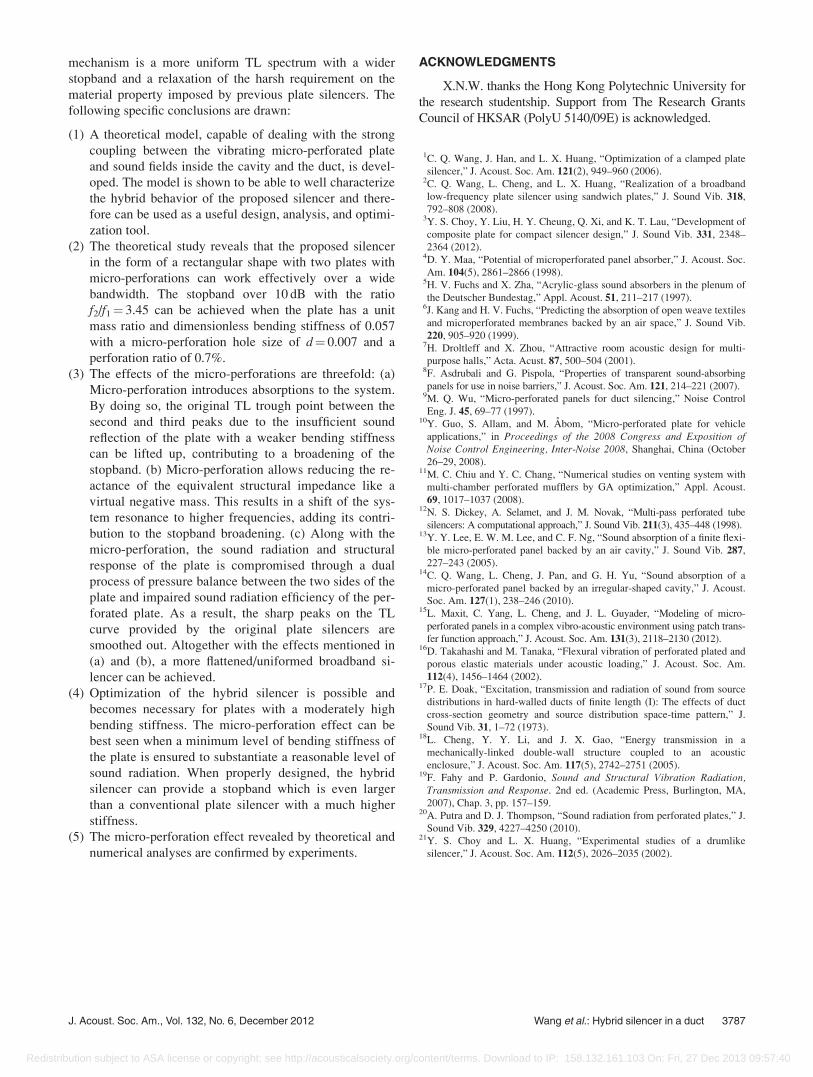
Figure 8(b) shows a photo of the configuration of the
PMI foam plate reinforced with CF. The use of PMI is to
reduce the mass of the plate while achieving the desired stiff-
ness. As a type of porous material, seen in Fig. 9(a), however,
the manufacturing process of drilling micro-perforated holes
by a laser machine turned out to be very tedious and difficult
to control the exact size of each hole as well as its shape. One
typical drilled micro-perforated hole is shown in Fig. 9(b),
illustrating the irregular shape of the hole. A close examina-
tion of the hole typology using a microscope revealed that
the range of the drilled-hole diameter varied from 0.2 to
0.9 mm by using the laser drilling on this type of material,
while the expected hole diameter is 0.4 mm. Therefore the
intention here is not to validate the accuracy of the theoretical
prediction. Instead, we would rather focus on confirming the
micro-perforation effect predicted in the above analyses.
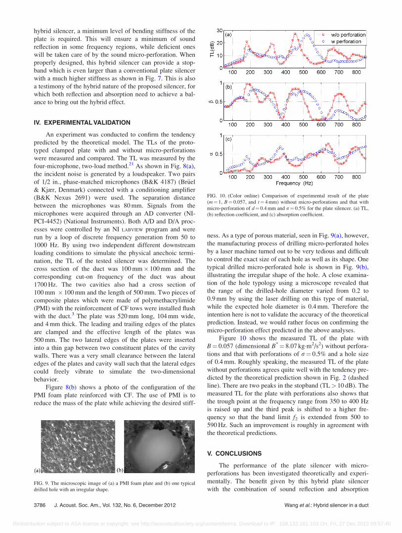
Figure 10 shows the measured TL of the plate with
B¼ 0.057 (dimensional B*¼ 8.07 kg�m2/s2) without perfora-
tions and that with perforations of r¼ 0.5% and a hole size
of 0.4 mm. Roughly speaking, the measured TL of the plate
without perforations agrees quite well with the tendency pre-
dicted by the theoretical prediction shown in Fig. 2 (dashed
line). There are two peaks in the stopband (TL> 10 dB). The
measured TL for the plate with perforations also shows that
the trough point at the frequency range from 350 to 400 Hz
is raised up and the third peak is shifted to a higher fre-
quency so that the band limit f2 is extended from 500 to
590 Hz. Such an improvement is roughly in agreement with
the theoretical predictions.
V. CONCLUSIONS
The performance of the plate silencer with micro-
perforations has been investigated theoretically and experi-
mentally. The benefit given by this hybrid plate silencer
with the combination of sound reflection and absorptionFIG. 9. The microscopic image of (a) a PMI foam plate and (b) one typical
drilled hole with an irregular shape.
FIG. 10. (Color online) Comparison of experimental result of the plate
(m¼ 1, B¼ 0.057, and t¼ 4 mm) without micro-perforations and that with
micro-perforation of d¼ 0.4 mm and r¼ 0.5% for the plate silencer. (a) TL,
(b) reflection coefficient, and (c) absorption coefficient.
3786 J. Acoust. Soc. Am., Vol. 132, No. 6, December 2012 Wang et al.: Hybrid silencer in a duct
Redistribution subject to ASA license or copyright; see http://acousticalsociety.org/content/terms. Download to IP: 158.132.161.103 On: Fri, 27 Dec 2013 09:57:40
mechanism is a more uniform TL spectrum with a wider
stopband and a relaxation of the harsh requirement on the
material property imposed by previous plate silencers. The
following specific conclusions are drawn:
(1) A theoretical model, capable of dealing with the strong
coupling between the vibrating micro-perforated plate
and sound fields inside the cavity and the duct, is devel-
oped. The model is shown to be able to well characterize
the hybrid behavior of the proposed silencer and there-
fore can be used as a useful design, analysis, and optimi-
zation tool.
(2) The theoretical study reveals that the proposed silencer
in the form of a rectangular shape with two plates with
micro-perforations can work effectively over a wide
bandwidth. The stopband over 10 dB with the ratio
f2/f1¼ 3.45 can be achieved when the plate has a unit
mass ratio and dimensionless bending stiffness of 0.057
with a micro-perforation hole size of d¼ 0.007 and a
perforation ratio of 0.7%.
(3) The effects of the micro-perforations are threefold: (a)
Micro-perforation introduces absorptions to the system.
By doing so, the original TL trough point between the
second and third peaks due to the insufficient sound
reflection of the plate with a weaker bending stiffness
can be lifted up, contributing to a broadening of the
stopband. (b) Micro-perforation allows reducing the re-
actance of the equivalent structural impedance like a
virtual negative mass. This results in a shift of the sys-
tem resonance to higher frequencies, adding its contri-
bution to the stopband broadening. (c) Along with the
micro-perforation, the sound radiation and structural
response of the plate is compromised through a dual
process of pressure balance between the two sides of the
plate and impaired sound radiation efficiency of the per-
forated plate. As a result, the sharp peaks on the TL
curve provided by the original plate silencers are
smoothed out. Altogether with the effects mentioned in
(a) and (b), a more flattened/uniformed broadband si-
lencer can be achieved.
(4) Optimization of the hybrid silencer is possible and
becomes necessary for plates with a moderately high
bending stiffness. The micro-perforation effect can be
best seen when a minimum level of bending stiffness of
the plate is ensured to substantiate a reasonable level of
sound radiation. When properly designed, the hybrid
silencer can provide a stopband which is even larger
than a conventional plate silencer with a much higher
stiffness.
(5) The micro-perforation effect revealed by theoretical and
numerical analyses are confirmed by experiments.
ACKNOWLEDGMENTS
X.N.W. thanks the Hong Kong Polytechnic University for
the research studentship. Support from The Research Grants
Council of HKSAR (PolyU 5140/09E) is acknowledged.
1C. Q. Wang, J. Han, and L. X. Huang, “Optimization of a clamped plate
silencer,” J. Acoust. Soc. Am. 121(2), 949–960 (2006).2C. Q. Wang, L. Cheng, and L. X. Huang, “Realization of a broadband
low-frequency plate silencer using sandwich plates,” J. Sound Vib. 318,
792–808 (2008).3Y. S. Choy, Y. Liu, H. Y. Cheung, Q. Xi, and K. T. Lau, “Development of
composite plate for compact silencer design,” J. Sound Vib. 331, 2348–
2364 (2012).4D. Y. Maa, “Potential of microperforated panel absorber,” J. Acoust. Soc.
Am. 104(5), 2861–2866 (1998).5H. V. Fuchs and X. Zha, “Acrylic-glass sound absorbers in the plenum of
the Deutscher Bundestag,” Appl. Acoust. 51, 211–217 (1997).6J. Kang and H. V. Fuchs, “Predicting the absorption of open weave textiles
and microperforated membranes backed by an air space,” J. Sound Vib.
220, 905–920 (1999).7H. Droltleff and X. Zhou, “Attractive room acoustic design for multi-
purpose halls,” Acta. Acust. 87, 500–504 (2001).8F. Asdrubali and G. Pispola, “Properties of transparent sound-absorbing
panels for use in noise barriers,” J. Acoust. Soc. Am. 121, 214–221 (2007).9M. Q. Wu, “Micro-perforated panels for duct silencing,” Noise Control
Eng. J. 45, 69–77 (1997).10Y. Guo, S. Allam, and M. Abom, “Micro-perforated plate for vehicle
applications,” in Proceedings of the 2008 Congress and Exposition ofNoise Control Engineering, Inter-Noise 2008, Shanghai, China (October
26–29, 2008).11M. C. Chiu and Y. C. Chang, “Numerical studies on venting system with
multi-chamber perforated mufflers by GA optimization,” Appl. Acoust.
69, 1017–1037 (2008).12N. S. Dickey, A. Selamet, and J. M. Novak, “Multi-pass perforated tube
silencers: A computational approach,” J. Sound Vib. 211(3), 435–448 (1998).13Y. Y. Lee, E. W. M. Lee, and C. F. Ng, “Sound absorption of a finite flexi-
ble micro-perforated panel backed by an air cavity,” J. Sound Vib. 287,
227–243 (2005).14C. Q. Wang, L. Cheng, J. Pan, and G. H. Yu, “Sound absorption of a
micro-perforated panel backed by an irregular-shaped cavity,” J. Acoust.
Soc. Am. 127(1), 238–246 (2010).15L. Maxit, C. Yang, L. Cheng, and J. L. Guyader, “Modeling of micro-
perforated panels in a complex vibro-acoustic environment using patch trans-
fer function approach,” J. Acoust. Soc. Am. 131(3), 2118–2130 (2012).16D. Takahashi and M. Tanaka, “Flexural vibration of perforated plated and
porous elastic materials under acoustic loading,” J. Acoust. Soc. Am.
112(4), 1456–1464 (2002).17P. E. Doak, “Excitation, transmission and radiation of sound from source
distributions in hard-walled ducts of finite length (I): The effects of duct
cross-section geometry and source distribution space-time pattern,” J.
Sound Vib. 31, 1–72 (1973).18L. Cheng, Y. Y. Li, and J. X. Gao, “Energy transmission in a
mechanically-linked double-wall structure coupled to an acoustic
enclosure,” J. Acoust. Soc. Am. 117(5), 2742–2751 (2005).19F. Fahy and P. Gardonio, Sound and Structural Vibration Radiation,
Transmission and Response. 2nd ed. (Academic Press, Burlington, MA,
2007), Chap. 3, pp. 157–159.20A. Putra and D. J. Thompson, “Sound radiation from perforated plates,” J.
Sound Vib. 329, 4227–4250 (2010).21Y. S. Choy and L. X. Huang, “Experimental studies of a drumlike
silencer,” J. Acoust. Soc. Am. 112(5), 2026–2035 (2002).
J. Acoust. Soc. Am., Vol. 132, No. 6, December 2012 Wang et al.: Hybrid silencer in a duct 3787
Redistribution subject to ASA license or copyright; see http://acousticalsociety.org/content/terms. Download to IP: 158.132.161.103 On: Fri, 27 Dec 2013 09:57:40