Embed Size (px)
Citation preview
SECURITY AND COMMUNICATION NETWORKSSecurity Comm. Networks 2011; 4:33–43
Published online 9 December 2009 in Wiley Online Library (wileyonlinelibrary.com). DOI: 10.1002/sec.175
SPECIAL ISSUE PAPER
Hybrid pattern matching for trusted intrusiondetectionBenfano Soewito, Lucas Vespa, Ning Weng∗ and Haibo Wang
Department of Electrical and Computer Engineering, Southern Illinois University, Carbondale, IL, U.S.A.
ABSTRACT
Intrusion Detection Systems (IDSs) rely on pattern matching to detect and thwart a network attack by comparing packetswith a database of known attack patterns. The key requirements of trusted intrusion detection are accurate pattern matching,adaptive, and reliable reconfiguration for new patterns. To address these requirements, this paper presents a trusted intrusiondetection by utilizing hybrid pattern matching engines: FPGA-based and multicore-based pattern matching engine. Toachieve synchronization of these two pattern matching engines, methodologies including multi-threading DFA and clusteredstate coding have been developed. These hybrid pattern matching engines increases the reliability and trustworthy of intrusiondetection systems. Copyright © 2009 John Wiley & Sons, Ltd.
KEYWORDS
trusted computing; pattern matching; instruction detection; security
*Correspondence
Ning Weng, Department of Electrical and Computer Engineering, Southern Illinois University, Carbondale, IL 62901, U.S.A.E-mail: [email protected]
1. INTRODUCTION
Recent years have witnessed a dramatic increase of interestin the pattern matching problem, especially in networksecurity applications such as virus scanner, spam filters, andIntrusion Detection Systems (IDSs) [1--4]. The IDSs rely onthe pattern matching to determine an attack by comparingpackets with attack patterns. As such, the first requirementof trusted IDSs is accurate pattern matching.
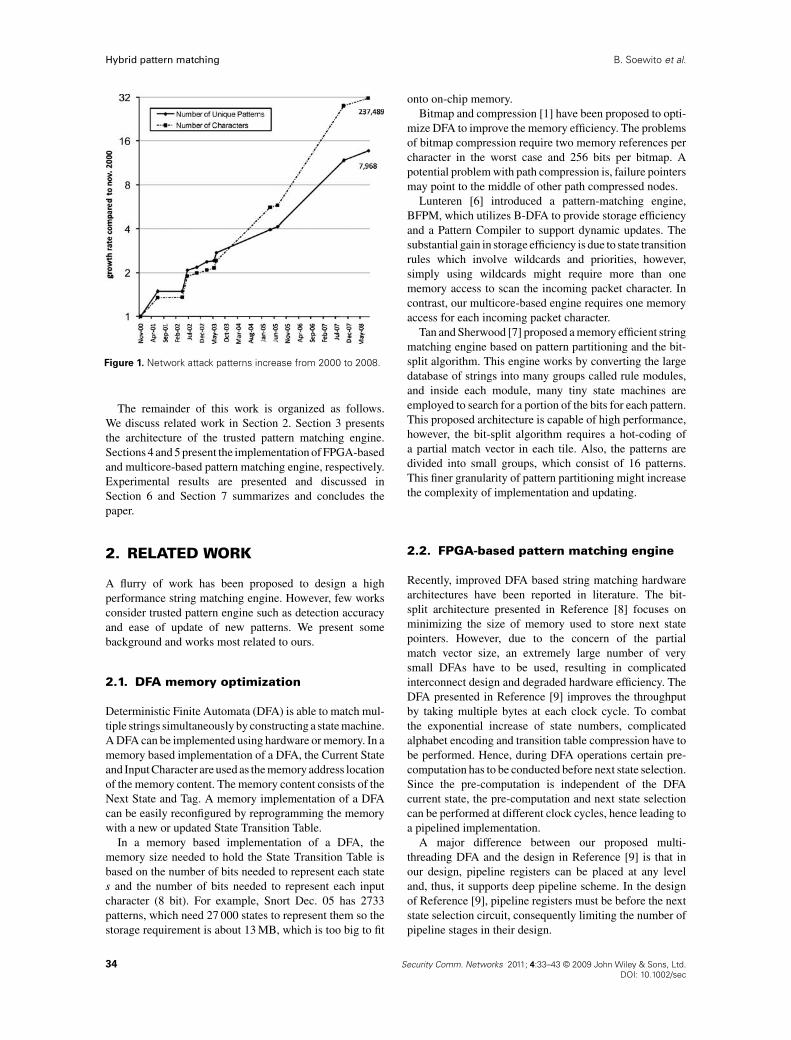
Meanwhile, new attack patterns are being createdfrequently, Figure 1 shows how the size of the Snort ruledatabase [5] has grown over time. We expect this trendwill continue. Therefore, adaptive pattern matching is thesecond requirement of a trusted IDSs. During the runtimefrequently reconfiguration, fault can be easily introducedeither accidently or maliciously, therefore, faithful patternreconfiguration is the third requirement to achieve a trustedIDSs.
To address these three requirements of IDSs, thispaper presents a trusted pattern matching engine shownin Figure 3. Our trusted matching engine improves itstrustworthy by employing two different pattern enginesworking in parallel. Each incoming packet is scanned byboth FPGA-based and multicore-based detection engines.The combined results of these two engines are used todetermine the packet type and the engine integrity.
One subtle issue for our trusted pattern engine isbalancing performance between our FPGA-based andmulticore-based matching engine. This is particularlychallenging as more patterns are added during runtime.To achieve this performance-balance, our two matchingengines must be reconfigurable for different performancerequirements. Our FPGA-based matching engine achievesreconfigurable performance using multi-threading DFA;our Multicore-based matching engine achieves scalableperformance by duplicating the memory-efficient softwarematching engine. The multi-threading FPGA-based andmulticore-based software matching engines are discussedin Sections 4 and 5, respectively.
Although pattern matching has been studied for manydifferent purposes in computer networks, our work isdifferent than previous work. The key features of our systemconsist of
� A trusted pattern matching engine which can improvethe attack detection accuracy and self integrity.
� A multi-threading FPGA-based detection engine,which can achieve high performance and is easilyreconfigurable for new patterns.
� An exceptionally memory efficient multicore-basedpattern matching engine which achieves memoryefficiency through novel state coding.
Copyright © 2009 John Wiley & Sons, Ltd. 33
Hybrid pattern matching B. Soewito et al.
Figure 1. Network attack patterns increase from 2000 to 2008.
The remainder of this work is organized as follows.We discuss related work in Section 2. Section 3 presentsthe architecture of the trusted pattern matching engine.Sections 4 and 5 present the implementation of FPGA-basedand multicore-based pattern matching engine, respectively.Experimental results are presented and discussed inSection 6 and Section 7 summarizes and concludes thepaper.
2. RELATED WORK
A flurry of work has been proposed to design a highperformance string matching engine. However, few worksconsider trusted pattern engine such as detection accuracyand ease of update of new patterns. We present somebackground and works most related to ours.
2.1. DFA memory optimization
Deterministic Finite Automata (DFA) is able to match mul-tiple strings simultaneously by constructing a state machine.A DFA can be implemented using hardware or memory. In amemory based implementation of a DFA, the Current Stateand Input Character are used as the memory address locationof the memory content. The memory content consists of theNext State and Tag. A memory implementation of a DFAcan be easily reconfigured by reprogramming the memorywith a new or updated State Transition Table.
In a memory based implementation of a DFA, thememory size needed to hold the State Transition Table isbased on the number of bits needed to represent each states and the number of bits needed to represent each inputcharacter (8 bit). For example, Snort Dec. 05 has 2733patterns, which need 27 000 states to represent them so thestorage requirement is about 13 MB, which is too big to fit
onto on-chip memory.Bitmap and compression [1] have been proposed to opti-
mize DFA to improve the memory efficiency. The problemsof bitmap compression require two memory references percharacter in the worst case and 256 bits per bitmap. Apotential problem with path compression is, failure pointersmay point to the middle of other path compressed nodes.
Lunteren [6] introduced a pattern-matching engine,BFPM, which utilizes B-DFA to provide storage efficiencyand a Pattern Compiler to support dynamic updates. Thesubstantial gain in storage efficiency is due to state transitionrules which involve wildcards and priorities, however,simply using wildcards might require more than onememory access to scan the incoming packet character. Incontrast, our multicore-based engine requires one memoryaccess for each incoming packet character.
Tan and Sherwood [7] proposed a memory efficient stringmatching engine based on pattern partitioning and the bit-split algorithm. This engine works by converting the largedatabase of strings into many groups called rule modules,and inside each module, many tiny state machines areemployed to search for a portion of the bits for each pattern.This proposed architecture is capable of high performance,however, the bit-split algorithm requires a hot-coding ofa partial match vector in each tile. Also, the patterns aredivided into small groups, which consist of 16 patterns.This finer granularity of pattern partitioning might increasethe complexity of implementation and updating.
2.2. FPGA-based pattern matching engine
Recently, improved DFA based string matching hardwarearchitectures have been reported in literature. The bit-split architecture presented in Reference [8] focuses onminimizing the size of memory used to store next statepointers. However, due to the concern of the partialmatch vector size, an extremely large number of verysmall DFAs have to be used, resulting in complicatedinterconnect design and degraded hardware efficiency. TheDFA presented in Reference [9] improves the throughputby taking multiple bytes at each clock cycle. To combatthe exponential increase of state numbers, complicatedalphabet encoding and transition table compression have tobe performed. Hence, during DFA operations certain pre-computation has to be conducted before next state selection.Since the pre-computation is independent of the DFAcurrent state, the pre-computation and next state selectioncan be performed at different clock cycles, hence leading toa pipelined implementation.
A major difference between our proposed multi-threading DFA and the design in Reference [9] is that inour design, pipeline registers can be placed at any leveland, thus, it supports deep pipeline scheme. In the designof Reference [9], pipeline registers must be before the nextstate selection circuit, consequently limiting the number ofpipeline stages in their design.
34 Security Comm. Networks 2011; 4:33–43 © 2009 John Wiley & Sons, Ltd.DOI: 10.1002/sec
B. Soewito et al. Hybrid pattern matching
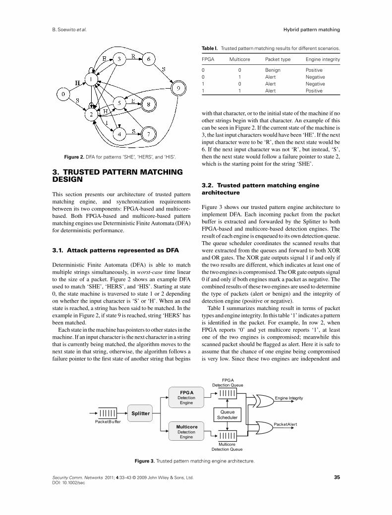
Figure 2. DFA for patterns ‘SHE’, ‘HERS’, and ‘HIS’.
3. TRUSTED PATTERN MATCHINGDESIGN
This section presents our architecture of trusted patternmatching engine, and synchronization requirementsbetween its two components: FPGA-based and multicore-based. Both FPGA-based and multicore-based patternmatching engines use Deterministic Finite Automata (DFA)for deterministic performance.
3.1. Attack patterns represented as DFA
Deterministic Finite Automata (DFA) is able to matchmultiple strings simultaneously, in worst-case time linearto the size of a packet. Figure 2 shows an example DFAused to match ‘SHE’, ‘HERS’, and ‘HIS’. Starting at state0, the state machine is traversed to state 1 or 2 dependingon whether the input character is ‘S’ or ‘H’. When an endstate is reached, a string has been said to be matched. In theexample in Figure 2, if state 9 is reached, string ‘HERS’ hasbeen matched.
Each state in the machine has pointers to other states in themachine. If an input character is the next character in a stringthat is currently being matched, the algorithm moves to thenext state in that string, otherwise, the algorithm follows afailure pointer to the first state of another string that begins
Table I. Trusted pattern matching results for different scenarios.
FPGA Multicore Packet type Engine integrity
0 0 Benign Positive0 1 Alert Negative1 0 Alert Negative1 1 Alert Positive
with that character, or to the initial state of the machine if noother strings begin with that character. An example of thiscan be seen in Figure 2. If the current state of the machine is3, the last input characters would have been ‘HE’. If the nextinput character were to be ‘R’, then the next state would be6. If the next input character was not ‘R’, but instead, ‘S’,then the next state would follow a failure pointer to state 2,which is the starting point for the string ‘SHE’.
3.2. Trusted pattern matching enginearchitecture
Figure 3 shows our trusted pattern engine architecture toimplement DFA. Each incoming packet from the packetbuffer is extracted and forwarded by the Splitter to bothFPGA-based and multicore-based detection engines. Theresult of each engine is enqueued to its own detection queue.The queue scheduler coordinates the scanned results thatwere extracted from the queues and forward to both XORand OR gates. The XOR gate outputs signal 1 if and only ifthe two results are different, which indicates at least one ofthe two engines is compromised. The OR gate outputs signal0 if and only if both engines mark a packet as negative. Thecombined results of these two engines are used to determinethe type of packets (alert or benign) and the integrity ofdetection engine (positive or negative).
Table I summarizes matching result in terms of packettypes and engine integrity. In this table ‘1’ indicates a patternis identified in the packet. For example, In row 2, whenFPGA reports ‘0’ and yet multicore reports ‘1’, at leastone of the two engines is compromised; meanwhile thisscanned packet should be flagged as alert. Here it is safe toassume that the chance of one engine being compromisedis very low. Since these two engines are independent and
FPG ADetectionEngine
Splitter
MulticoreDetectionEngine
Engine Integrity
PacketAlertPacketBuffer
FPGADetection Queue
QueueScheduler
MulticoreDetection Queue
Figure 3. Trusted pattern matching engine architecture.
Security Comm. Networks 2011; 4:33–43 © 2009 John Wiley & Sons, Ltd. 35DOI: 10.1002/sec
Hybrid pattern matching B. Soewito et al.
completely different in nature, the chance of both enginesbeing compromised is minute.
3.3. Matching engines performancebalancing and synchronization
One subtle issue for our trusted pattern engine is balancingperformance between the FPGA-based and multicore-basedmatching engine without one engine slowing down anotherone. This is particularly challenging as more patterns areadded during the runtime. To achieve this runtime synchro-nization, the two matching engines must be reconfigurablefor new patterns and easily tuned for different performance.
FPGA and multicore technologies are chosen toimplement these two matching engines because bothtechnologies are easily reconfigurable and easily tuned fordifferent performance by changing the number of packets tobe scanned in parallel. Our FPGA-based matching enginescans multiple packets in parallel using multi-threadingDFA (in Section 4). However, our multicore-based match-ing engine achieves parallelism by replicating the cluster-coded software matching engine (in Section 5). Once theperformance is balanced, the queue scheduler in Figure 3will synchronize these two engines to make sure thatmatching results are based on the same packet. In summary,this trusted pattern matching engine improves the detectionaccuracy by employing two different detection engines.
4. DETERMINISTIC FINITEAUTOMATA ON FPGA
This section presents multi-threading FPGA patternmatching engine architecture and the procedure to designthis multi-threading engine from DFA.
4.1. Multi-threading DFA
In conventional DFA-based string matching operations,packets to be examined are fed to the DFA one by onein a serial manner. This is analogous with different tasksbeing processed by a single-threading microprocessor ina sequential order. Similar to multi-threading techniquesimproving microprocessor performance, the throughput ofDFA-based string matching operations can be improved ifmultiple packets can be examined by the same DFA inparallel. In this paper, the DFA that can process multiplepackets at the same time is referred to as a multi-threadingDFA. Techniques to implement multi-threading DFAs aredescribed as follows.
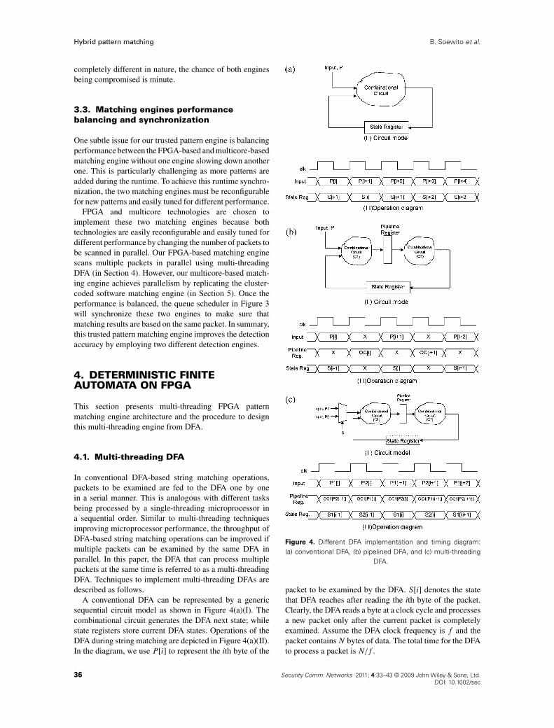
A conventional DFA can be represented by a genericsequential circuit model as shown in Figure 4(a)(I). Thecombinational circuit generates the DFA next state; whilestate registers store current DFA states. Operations of theDFA during string matching are depicted in Figure 4(a)(II).In the diagram, we use P[i] to represent the ith byte of the
Figure 4. Different DFA implementation and timing diagram:(a) conventional DFA, (b) pipelined DFA, and (c) multi-threading
DFA.
packet to be examined by the DFA. S[i] denotes the statethat DFA reaches after reading the ith byte of the packet.Clearly, the DFA reads a byte at a clock cycle and processesa new packet only after the current packet is completelyexamined. Assume the DFA clock frequency is f and thepacket contains N bytes of data. The total time for the DFAto process a packet is N/f .
36 Security Comm. Networks 2011; 4:33–43 © 2009 John Wiley & Sons, Ltd.DOI: 10.1002/sec
B. Soewito et al. Hybrid pattern matching
In general, the complexity of the combinational circuitis proportional to the number of string patterns encoded inthe DFA. Hence, if many string patterns are contained in anDFA, the propagation delay of the combinational circuit isincreased and the maximum clock frequency of the DFAis reduced. A straight forward approach to address thisproblem is to apply re-timing techniques: dividing the logicpropagation paths into sub-paths and inserting pipelineregisters in between. Although re-timing techniques havebeen widely applied in designing high-speed data pathcircuits, the use of such techniques in DFA design is rarelyreported. This is mainly because an DFA needs both currentinput and current state to generate its next state. Whileadding pipeline stages in the combinational circuit increasesthe clock frequency, it postpones the generation of DFAcurrent state. As a result, the overall DFA performance isnot improved. This is further illustrated in the followingexample.
Assume that the combinational circuit of the DFA shownin Figure 4(a) is partitioned into two parts and pipelineregisters are inserted between the partitioned circuits. Theresultant pipelined DFA and its operation are sketched inFigure 4(b). Note that C1 and C2 are used to label the twopartitioned circuits in the figure. At the ith clock cycle,P[i], the ith byte of packet P, is fed to the DFA and thestate register stores state S[i − 1], which corresponds toDFA input P[i − 1]. The C1 output, which is resulted frominputs P[i − 1] and S[i − 1], is latched into the pipelineregister at the end of the ith clock cycle, and is furtherprocessed by C2 during the (i + 1)th clock cycle. The DFAstate corresponding to input P[i] is latched to the stateregister at the end of the (i + 1)th clock cycle. Therefore,the DFA has to wait till the (i + 2)th clock cycle to takethe next input P[i + 1]. Apparently, the pipelined designdoubles the DFA clock frequency but takes an input everytwo clock cycles. Hence, the time to process a packet is stillthe same as that of the conventional DFA.
During half of the operation cycles, the combinationalcircuits and registers in the above design do not produceor store valid data. For example, the data stored in thestate register during the (i + 1)th clock cycle is uselessfor the operation of the DFA. For a pipelined DFA, werefer to a clock cycle as a utilized cycle for a register or acombinational circuit if the register stores a valid state or thecombinational circuit generates valid outputs. In addition,we call the clock cycles that the hardware does not store orgenerate valid data as its idle cycles. In Figure 4(b)(II), weuse ‘X’ to label the idle cycles.
An interesting property of pipelined DFAs is that datastored or produced during idle cycles do not affect thecorrectness of the DFA operation during its utilized cycles.This creates the possibility to let the idle DFA hardwareprocess other packets without affecting the DFA operationdesignated for the original packet. Thus, multiple packetscan be processed by a single DFA and a multi-threadingoperation is achieved. In network processing domain, thereis virtually no dependency between packets; therefore, allpackets can be processed in parallel. Figure 4(c) shows
a two-threading DFA and its operations. During the oddclock cycles, data from Packet P1 are fed to the DFA. Inan even clock cycle, the DFA takes input from Packet P2.As a snapshot of its operation, we assume at the ith clockcycle, where i is an odd number, data P1[i] (the ith byte ofP1) is fed to the DFA. Also, the DFA state register storesstate S1[i − 1], which corresponds to DFA input P1[i − 1].Thus, during the ith clock cycle, combinational circuitC1 computes partial results, which will be used by C2 togenerate DFA state S1[i] in the (i + 1)th clock cycle. Parallelwith the computation for Packet P1, circuit C2 computesthe DFA state S2[i − 1] for Packet P2 during the ith clockcycle. Consequently, at the (i + 1)th clock cycle the stateregister stores state S2[i − 1] and circuit C1 processes inputP2[i] from Packet P2. Note that for an DFA with M pipelinestages, M packets can be processed simultaneously. Hence,we refer to it as a M-threading DFA.
If we ignore the performance penalty caused by theDFA input multiplexer and pipeline stage registers, thethroughput of M-threading DFA is M times faster than aconventional DFA (though the latencies of the two are thesame). To maximize the system throughput, M is preferredto be as large as possible. On FPGA implementations,
Algorithm 1 Steps to construct multithreading FPGAmatching engine
Security Comm. Networks 2011; 4:33–43 © 2009 John Wiley & Sons, Ltd. 37DOI: 10.1002/sec
Hybrid pattern matching B. Soewito et al.
Figure 5. Levelization.
the value of M can be maximized by adding a pipelinestage after each look-up table (LUT). Modern FPGAs haveabundant DFFs to support this deep pipeline scheme. Thisobservation is supported by our experimental results to bepresented in Section 6.
4.2. Method to derive multi-thread DFA
Here we present a methodology to derive a multi-threadedDFA. There are four steps: Construct DeterministicFinite Automata (DFA), Making acyclic, Levelization, andPartition, as shown in Algorithm 1 (lines 1–7).
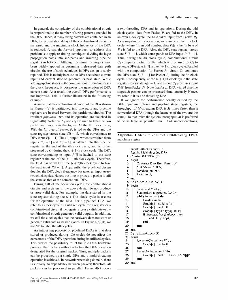
The key step is to make the DFA acyclic (lines 8–21). Thetechnique to make the DFA acyclic starts with generatingVerilog code to represent the DFA. Then the Verilog codeis synthesized, generating a netlist. Then a directed graphis formed from the netlist. Each component in the netlist isa node in the graph. At this point the graph still containscycles. To remove the cycles we add dummy D flip-flopsand primary inputs and outputs on every component thatcontains a cycle.
The second key step is levelization (lines 22–30). Inthis step we start by labeling each node in the graph witha number representing its hierarchical level in the graph.All labeling begins with the primary inputs being assignedlevel zero. Subsequently, the nodes that have input from theprimary inputs are labeled with level one and so on. Figure 5shows an example of the levelization.
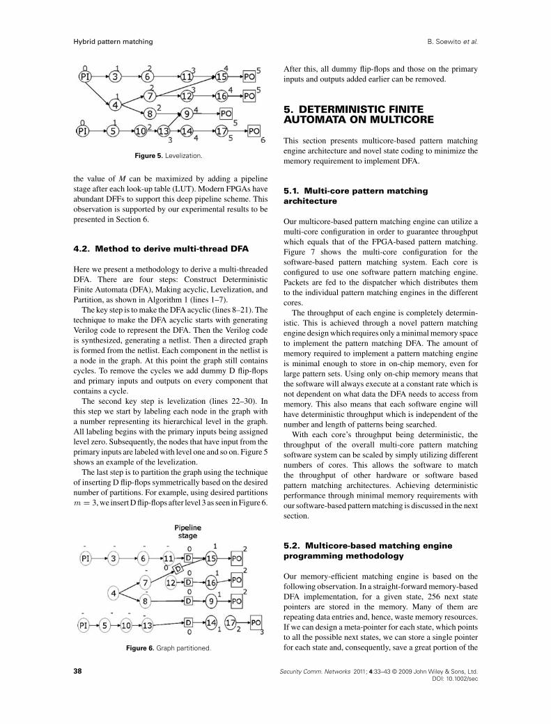
The last step is to partition the graph using the techniqueof inserting D flip-flops symmetrically based on the desirednumber of partitions. For example, using desired partitionsm = 3, we insert D flip-flops after level 3 as seen in Figure 6.
Figure 6. Graph partitioned.
After this, all dummy flip-flops and those on the primaryinputs and outputs added earlier can be removed.
5. DETERMINISTIC FINITEAUTOMATA ON MULTICORE
This section presents multicore-based pattern matchingengine architecture and novel state coding to minimize thememory requirement to implement DFA.
5.1. Multi-core pattern matchingarchitecture
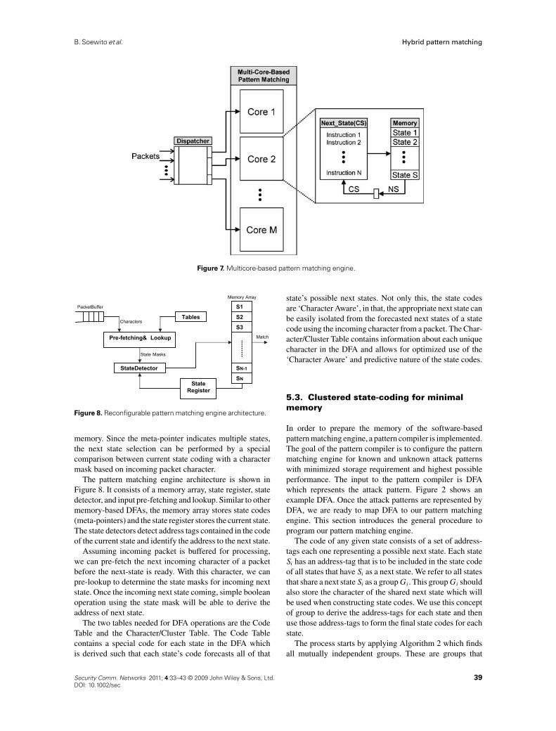
Our multicore-based pattern matching engine can utilize amulti-core configuration in order to guarantee throughputwhich equals that of the FPGA-based pattern matching.Figure 7 shows the multi-core configuration for thesoftware-based pattern matching system. Each core isconfigured to use one software pattern matching engine.Packets are fed to the dispatcher which distributes themto the individual pattern matching engines in the differentcores.
The throughput of each engine is completely determin-istic. This is achieved through a novel pattern matchingengine design which requires only a minimal memory spaceto implement the pattern matching DFA. The amount ofmemory required to implement a pattern matching engineis minimal enough to store in on-chip memory, even forlarge pattern sets. Using only on-chip memory means thatthe software will always execute at a constant rate which isnot dependent on what data the DFA needs to access frommemory. This also means that each software engine willhave deterministic throughput which is independent of thenumber and length of patterns being searched.
With each core’s throughput being deterministic, thethroughput of the overall multi-core pattern matchingsoftware system can be scaled by simply utilizing differentnumbers of cores. This allows the software to matchthe throughput of other hardware or software basedpattern matching architectures. Achieving deterministicperformance through minimal memory requirements withour software-based pattern matching is discussed in the nextsection.
5.2. Multicore-based matching engineprogramming methodology
Our memory-efficient matching engine is based on thefollowing observation. In a straight-forward memory-basedDFA implementation, for a given state, 256 next statepointers are stored in the memory. Many of them arerepeating data entries and, hence, waste memory resources.If we can design a meta-pointer for each state, which pointsto all the possible next states, we can store a single pointerfor each state and, consequently, save a great portion of the
38 Security Comm. Networks 2011; 4:33–43 © 2009 John Wiley & Sons, Ltd.DOI: 10.1002/sec
B. Soewito et al. Hybrid pattern matching
Figure 7. Multicore-based pattern matching engine.
Match
Memory Array
.........PacketBuffer
State Masks
Characters
Pre-fetching& Lookup
Tables
StateDetector
StateRegister
SN-1
S2
S3
SN
S1
Figure 8. Reconfigurable pattern matching engine architecture.
memory. Since the meta-pointer indicates multiple states,the next state selection can be performed by a specialcomparison between current state coding with a charactermask based on incoming packet character.
The pattern matching engine architecture is shown inFigure 8. It consists of a memory array, state register, statedetector, and input pre-fetching and lookup. Similar to othermemory-based DFAs, the memory array stores state codes(meta-pointers) and the state register stores the current state.The state detectors detect address tags contained in the codeof the current state and identify the address to the next state.
Assuming incoming packet is buffered for processing,we can pre-fetch the next incoming character of a packetbefore the next-state is ready. With this character, we canpre-lookup to determine the state masks for incoming nextstate. Once the incoming next state coming, simple booleanoperation using the state mask will be able to derive theaddress of next state.
The two tables needed for DFA operations are the CodeTable and the Character/Cluster Table. The Code Tablecontains a special code for each state in the DFA whichis derived such that each state’s code forecasts all of that
state’s possible next states. Not only this, the state codesare ‘Character Aware’, in that, the appropriate next state canbe easily isolated from the forecasted next states of a statecode using the incoming character from a packet. The Char-acter/Cluster Table contains information about each uniquecharacter in the DFA and allows for optimized use of the‘Character Aware’ and predictive nature of the state codes.
5.3. Clustered state-coding for minimalmemory
In order to prepare the memory of the software-basedpattern matching engine, a pattern compiler is implemented.The goal of the pattern compiler is to configure the patternmatching engine for known and unknown attack patternswith minimized storage requirement and highest possibleperformance. The input to the pattern compiler is DFAwhich represents the attack pattern. Figure 2 shows anexample DFA. Once the attack patterns are represented byDFA, we are ready to map DFA to our pattern matchingengine. This section introduces the general procedure toprogram our pattern matching engine.
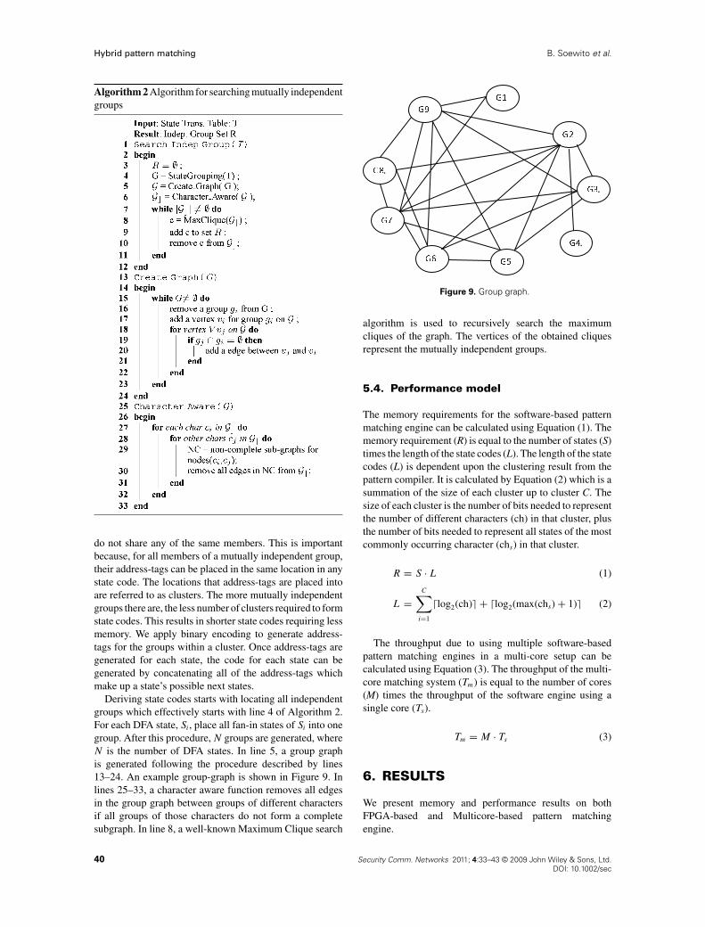
The code of any given state consists of a set of address-tags each one representing a possible next state. Each stateSi has an address-tag that is to be included in the state codeof all states that have Si as a next state. We refer to all statesthat share a next state Si as a group Gi. This group Gi shouldalso store the character of the shared next state which willbe used when constructing state codes. We use this conceptof group to derive the address-tags for each state and thenuse those address-tags to form the final state codes for eachstate.
The process starts by applying Algorithm 2 which findsall mutually independent groups. These are groups that
Security Comm. Networks 2011; 4:33–43 © 2009 John Wiley & Sons, Ltd. 39DOI: 10.1002/sec
Hybrid pattern matching B. Soewito et al.
Algorithm 2 Algorithm for searching mutually independentgroups
do not share any of the same members. This is importantbecause, for all members of a mutually independent group,their address-tags can be placed in the same location in anystate code. The locations that address-tags are placed intoare referred to as clusters. The more mutually independentgroups there are, the less number of clusters required to formstate codes. This results in shorter state codes requiring lessmemory. We apply binary encoding to generate address-tags for the groups within a cluster. Once address-tags aregenerated for each state, the code for each state can begenerated by concatenating all of the address-tags whichmake up a state’s possible next states.
Deriving state codes starts with locating all independentgroups which effectively starts with line 4 of Algorithm 2.For each DFA state, Si, place all fan-in states of Si into onegroup. After this procedure, N groups are generated, whereN is the number of DFA states. In line 5, a group graphis generated following the procedure described by lines13–24. An example group-graph is shown in Figure 9. Inlines 25–33, a character aware function removes all edgesin the group graph between groups of different charactersif all groups of those characters do not form a completesubgraph. In line 8, a well-known Maximum Clique search
Figure 9. Group graph.
algorithm is used to recursively search the maximumcliques of the graph. The vertices of the obtained cliquesrepresent the mutually independent groups.
5.4. Performance model
The memory requirements for the software-based patternmatching engine can be calculated using Equation (1). Thememory requirement (R) is equal to the number of states (S)times the length of the state codes (L). The length of the statecodes (L) is dependent upon the clustering result from thepattern compiler. It is calculated by Equation (2) which is asummation of the size of each cluster up to cluster C. Thesize of each cluster is the number of bits needed to representthe number of different characters (ch) in that cluster, plusthe number of bits needed to represent all states of the mostcommonly occurring character (chs) in that cluster.
R = S · L (1)
L =C∑
i=1
�log2(ch)� + �log2(max(chs) + 1)� (2)
The throughput due to using multiple software-basedpattern matching engines in a multi-core setup can becalculated using Equation (3). The throughput of the multi-core matching system (Tm) is equal to the number of cores(M) times the throughput of the software engine using asingle core (Ts).
Tm = M · Ts (3)
6. RESULTS
We present memory and performance results on bothFPGA-based and Multicore-based pattern matchingengine.
40 Security Comm. Networks 2011; 4:33–43 © 2009 John Wiley & Sons, Ltd.DOI: 10.1002/sec
B. Soewito et al. Hybrid pattern matching
6.1. FPGA-based pattern matching engine
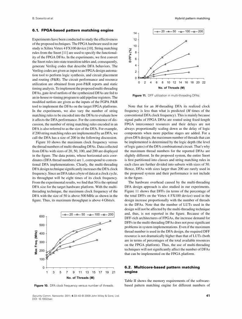
Experiments have been conducted to study the effectivenessof the proposed techniques. The FPGA hardware used in ourstudy is Xilinx Virtex 4 FX100 device [10]. String matchingrules from the Snort [11] are used to specify the functional-ity of the FPGA DFAs. In the experiments, we first convertthe Snort rules into state transition tables and, consequently,generate Verilog codes that describe DFA behaviors. TheVerilog codes are given as input to an FPGA design automa-tion tool to perform logic synthesis, and circuit placementand routing (P&R). The circuit performance and resourceutilization are obtained from post-P&R reports and statictiming analysis. To implement the proposed multi-threadingDFAs, gate-level netlists of the synthesized DFAs are fed toan in-house re-timing program to add pipeline registers. Themodified netlists are given as the inputs of the FGPA P&Rtool to implement the DFAs on the target FPGA platforms.In the experiments, we also vary the number of stringmatching rules to be encoded into the DFAs to evaluate howit affects the DFA performance. For the convenience of dis-cussion, the number of string matching rules encoded in anDFA is also referred to as the size of the DFA. For example,if 200 string matching rules are implemented by an DFA, wecall the DFA has a size of 200 in the following discussion.
Figure 10 shows the maximum clock frequency versusthe thread numbers of multi-threading DFAs. Data collectedfrom DFAs with sizes of 20, 50, 100, and 200 are displayedin the figure. The data points, whose horizontal-axis coor-dinates (DFA thread numbers) are 1, correspond to conven-tional DFA implementations. Clearly, the multi-threadingDFA design technique significantly increases the DFA clockfrequency. Since an DFA takes a byte of data at a clock cycle,its throughput will be eight times of its clock frequency.From the experimental results, we find that 50 is the optimalDFA size for the target hardware platform. With the multi-threading technique, the maximum clock frequency of theDFA with the size of 50 is above 500 MHz as shown in thefigure. Thus, its maximum throughput is above 4 Gbits/s.
0
100
200
300
400
500
600
31 75 119 13 15 17 19 21
No. of Threads (M)
Max
Freq
.(M
Hz)
20 50 100 200
Figure 10. DFA clock frequency versus number of threads.
0
2
4
6
8
10
12
14
420 86 10 12 14 16 18 20 22
No. of Threads (M)
DFF
's(%
)
20 50 100 200
Figure 11. DFF utilization in multi-threading DFAs.
Note that for an M-threading DFA its realized clockfrequency is less than what is predicted (M times of theconventional DFA clock frequency). This is mainly becausesignal paths of FPGA DFAs are routed using fixed-lengthFPGA interconnect resources and their delays are notalways proportionally scaling down as the delay of logiccomponents when more pipeline stages are added. For agiven DFA design, the maximum number of threads that canbe implemented is determined by the logic depth (the levelof logic gates) of the DFA combinational circuit. That’s whythe maximum thread numbers for the reported DFAs areslightly different. In the proposed system, the entire Snortis first partitioned into classes and string matching rules ineach class are further divided into subsets with sizes of 50.Hence, DFAs with sizes larger than 200 are rarely used inthe proposed system and their performance is not includein the figure.
The hardware overhead caused by the multi-threadingDFA design approach is also studied in our experiments.Figure 11 shows that DFFs (in terms of the percentage ofthe total DFFs on the Virtex 4 FX100 device) used in thedesign increase proportionally with the number of threadsin the DFAs. Note that the number of LUTs used in thedesign will not be affected by the multi-threading techniqueand, thus, is not reported in the figure. Because of theDFF-rich architectures of FPGAs, the increase demand forDFFs in the multi-threading DFAs does not pose significantproblems in system implementations. Even if the maximumthread number is used in the DFA design, the required DFFresource is not dramatically higher than that of LUTs (bothare in terms of percentages of the total available resourceson the FPGA platform). Thus, the use of multi-threadingtechniques will not significantly affect the number of DFAsthat can be implemented on the FPGA platform.
6.2. Multicore-based pattern matchingengine
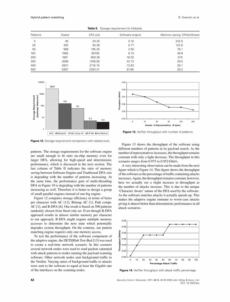
Table II shows the memory requirements of the software-based pattern matching engine for different numbers of
Security Comm. Networks 2011; 4:33–43 © 2009 John Wiley & Sons, Ltd. 41DOI: 10.1002/sec
Hybrid pattern matching B. Soewito et al.
Table II. Storage requirement (in kilobyte).
Patterns States DFA size Software engine Memory saving: DFA/software
5 93 23.25 0.10 232.520 302 94.38 0.77 122.650 568 195.25 2.50 78.1
100 1060 397.50 8.15 48.8200 1601 600.38 16.03 37.5300 3098 1258.56 42.73 29.5400 4837 2116.19 72.63 29.1500 5267 2304.31 81.65 28.2
2800
154
60
5.4 4.2
1
10
100
1000
10000
Sto
rage
Req
uire
men
t(b
ytes
per
char
acte
r)
AC BitmapAC Path Compr AC B-FSM Our Method
Figure 12. Storage requirement comparison with related work.
patterns. The storage requirements for the software engineare small enough to fit onto on-chip memory even forlarger DFA, allowing for high-speed and deterministicperformance, which is discussed in the next section. Thelast column of Table II indicates the ratio of memorysaving between Software Engine and Traditional DFA sizeis degrading with the number of patterns increasing. Atthe same time, the performance gain of multi-threadingDFA in Figure 10 is degrading with the number of patternsincreasing as well. Therefore it is better to design a groupof small parallel engines instead of one big engine.
Figure 12 compares storage efficiency in terms of bytesper character with AC [12], Bitmap AC [1], Path compr.AC [1], and B-DFA [6]. Our result is based on 500 patternsrandomly chosen from Snort rule set. Even though B-DFAapproach results in almost similar memory per characterto our approach, B-DFA might require multiple memoryaccesses to determine the next state which potentiallydegrades system throughput. On the contrary, our patternmatching engine requires only one memory access.
To test the performance of the software component ofthe adaptive engine, the DETERlab Test-Bed [13] was usedto create a real-time network scenario. In this scenarioseveral network nodes were used to send packets saturatedwith attack patterns to nodes running the payload scanningsoftware. Other network nodes sent background traffic tothe Verifier. Varying ratios of background traffic to attackswere sent to the software to equal at least the Gigabit rateof the interfaces on the scanning nodes.
0.94
0.95
0.96
0.97
0.98
0.99
105 20 50 100 200
Number of Representatives (8 bytes)
Thro
ughp
ut(G
bit/s
)
Figure 13. Verifier throughput with number of patterns.
Figure 13 shows the throughput of the software usingdifferent numbers of patterns in its payload search. As thenumber of representatives increases, the throughput remainsconstant with only a light decrease. The throughput in thisscenario ranges from 0.975 to 0.952 Gbit/s.
A very interesting observation can be made from the nextfigure which is Figure 14. This figure shows the throughputof the software as the percentage of traffic containing attacksincreases. Again, the throughput remains constant, however,here we actually see a slight increase in throughput asthe number of attacks increase. This is due to the unique‘Character Aware’ nature of the DFA used by the software.As the software matches attacks it actually speeds up. Thismakes the adaptive engine immune to worst-case attacksgiving it almost better than deterministic performance in allattack scenarios.
0.94
0.94
0.94
0.94
0.95
0.95
0.95
100 20 30 40 50 60 70 80 90 100Percentage Attack Traffic
Thro
ughp
ut (G
bit/s
)
Figure 14. Verifier throughput with attack traffic percentage.
42 Security Comm. Networks 2011; 4:33–43 © 2009 John Wiley & Sons, Ltd.DOI: 10.1002/sec
B. Soewito et al. Hybrid pattern matching
7. CONCLUSION
In this work, we first identify three key requirementsof trusted intrusion detection: accurate pattern matching,adaptive, and reliable reconfiguration for new patterns. Toaddress these requirements, we present a hybrid patternmatching engine: FPGA-based and multicore-based patternmatching engines. These two engines work in parallelto improve detection accuracy and cross-examine to self-check integrity of the engine. These are very important,considering frequent run-time reconfiguration is required toadapt new attack patterns. Particularly, two key techniques(multi-threading and novel clustered state coding) areemployed to optimize FPGA-based and multicore-basedengine respectively. Automatical methods to design thesetwo engine have been developed and tested. Experimentalresults have shown the efficiency of our approach.
In summary, we have presented a trusted pattern matchingengine architecture, optimization techniques, and designmethods. This trusted pattern matching engine will increasethe trustworthiness of network security applications, such asvirus scanner, spam filter, and intrusion detections systems.
REFERENCES
1. Tuck N, Sherwood T, Calder B, Varghese G. Determin-istic memory-efficient string matching algorithms forintrusion detection. In Proceedings of the IEEE Infocom
Conference, 2004; 333–340.2. Denning D. An intrusion–detection model. IEEE
Transactions on Software Engineering 1987; 13(2): 222–232.
3. Roesch M. Snort—lightweight intrusion detectionfor networks. In Proceedings of the 13th Systems
Administration Conference, 1999.4. Soewito B, Vespa L, Mahajan A, Weng N, Wang H. Self
addressable memory-based fsm (sam-fsm): a scalable
intrusion detection engine. IEEE Network Special Issue
on Recent Developments in Network Intrusion Detection
2009; 23(1): 14–21.5. Snort. Snort Rule Database, 2007. Available at: http://
www.snort.org/pub-bin/downloads.cgi6. van Lunteren J. High-performance pattern-matching
for intrusion detection. INFOCOM 2006. 25th IEEE
International Conference on Computer Communications.
Proceedings, 2006; 1–13.7. Tan L, Sherwood T. A high throughput string matching
architecture for intrusion detection and prevention. InISCA ’05: Proceedings of the 32nd Annual International
Symposium on Computer Architecture, Washington, DC,USA, 2005; 112–122 (IEEE Computer Society).
8. Tan L, Sherwood T. Architectures for bit-split stringscanning in intrusion detection. IEEE Micro 2006; (1):2–9.
9. Brodie B, Cytron R, Taylor D. A scalable architecturefor high-throughput regular-expression pattern matching.In Proceedings of 33rd International Symposium on
Computer Architecture, 2006.10. Xilinx, Inc. Virtex-IV Pro and Virtex-IV Pro X Platform
FPGAs: Complete Data Sheet, 2004. Available at:http://www.xilinx.com
11. Snort, Inc. The Open Source Network Instrusion Detec-
tion System, 2004. Available at: http://www.snort.org12. Schwab S, Corasick M. Efficient string matching: an aid
to bibliographic search. Communications of the ACM
1975; 18(6): 333–340.13. Aho A, Wilson B, Ko C, Hussain A. Seer: a security
experimentation environment for deter. In DETER:
Proceedings of the DETER Community Workshop
on Cyber Security Experimentation and Test on
DETER Community Workshop on Cyber Security
Experimentation and Test 2007, Berkeley, CA, USA,2007 (USENIX Association).
Security Comm. Networks 2011; 4:33–43 © 2009 John Wiley & Sons, Ltd. 43DOI: 10.1002/sec