Embed Size (px)
Citation preview

M. Rebato, F. Boccardi, M. Mezzavilla, S. Rangan and M. Zorzi, ”Hybrid Spectrum Sharing in mmWave Cellular Networks,” in IEEETransactions on Cognitive Communications and Networking, vol. 3, no. 2, pp. 155-168, June 2017. doi: 10.1109/TCCN.2017.2707551
Hybrid Spectrum Sharing in mmWave CellularNetworks
Mattia Rebato, Federico Boccardi, Senior Member, IEEE, Marco Mezzavilla, Member, IEEE, Sundeep Rangan,Fellow, IEEE, Michele Zorzi, Fellow, IEEE
Abstract—While spectrum at millimeter wave (mmWave) fre-quencies is less scarce than at traditional frequencies below6 GHz, still it is not unlimited, in particular if we consider therequirements from other services using the same band and theneed to license mmWave bands to multiple mobile operators.Therefore, an efficient spectrum access scheme is critical toharvest the maximum benefit from emerging mmWave technolo-gies. In this paper, we introduce a new hybrid spectrum accessscheme for mmWave networks, where data packets are scheduledthrough two mmWave carriers with different characteristics. Inparticular, we consider the case of a hybrid spectrum schemebetween a mmWave band with exclusive access and a mmWaveband where spectrum is pooled between multiple operators. Tothe best of our knowledge, this is the first study proposinghybrid spectrum access for mmWave networks and providinga quantitative assessment of its benefits. Our results show thatthis approach provides advantages with respect to traditionalfully licensed or fully pooled spectrum access schemes, thoughfurther work is needed to achieve a more complete understandingof both technical and non technical implications.
Index Terms—5G, mmWave, cellular systems, spectrum access,hybrid access, spectrum sharing.
I. INTRODUCTION
Millimeter wave (mmWave) communications are emergingas a key disruptive technology for both cellular networks(5G and beyond) [2]–[6] and wireless Local Area Networks(802.11ad and beyond) [7], [8]. While spectrum is extremelylimited in traditional bands below 6 GHz, mmWave frequen-cies offer potentially up to two orders of magnitude greaterbandwidths. In addition, thanks to the small wavelength, anddue to the need to compensate for the higher path lossat these frequencies, mmWave communications are typicallycharacterized by transmission and reception with very narrowbeams, enabling further gains from directional isolation be-tween mobiles [9], [10].
This combination of massive bandwidth and spatial degreesof freedom may make it possible for mmWave to meet someof the boldest 5G requirements, including higher peak per-userdata rate, high traffic density, and very low latency [11], [12].
M. Rebato and M. Zorzi are with the Department of InformationEngineering, University of Padova, Italy (e-mail: [email protected];[email protected]).
F. Boccardi is with Ofcom, London SE1 9HA, U.K. (e-mail: [email protected]).
M. Mezzavilla and S. Rangan are with NYU WIRELESS, Tandon Schoolof Engineering, New York University, Brooklyn, NY (e-mail: [email protected]; [email protected])
A preliminary version of this paper was presented at the MED-HOC-NETconference, June 2016 [1].
However, even the abundant spectrum at mmWave is obviouslynot unlimited, in particular if we consider the requirementsfrom other services (e.g., satellite and fixed services [13])and the need to license mmWave bands to multiple mobileoperators. Therefore, an efficient spectrum access schemeis critical to harvest the maximum benefit from emergingmmWave technologies [14].
As regulatory authorities are considering opening up somemmWave bands for cellular use, the licensing and usagemodels for these bands require some studies. At root, themmWave bands present three unique features not present atlower frequencies. First, due to the massive bandwidth andspatial degrees of freedom, the mmWave bands could be highlyunder-utilized if large bandwidths are allocated exclusively toa single operator. For example, a scaling law analysis in [15] aswell as simulations in [16] demonstrate that links may becomepower-limited in wide bandwidth regimes, thereby forgoingthe benefits of the large numbers of degrees of freedom.Second, mmWave communications are typically characterizedby transmissions with very narrow beams. Third, mmWavesignals suffer from major propagation-related shortcomings,such as a relatively short range and the difficulty of providinga robust connection, which makes it challenging to provide aconsistent user experience. To overcome these shortcomings,mmWave networks have been usually envisioned in the contextof heterogeneous deployments [17]–[20], where part of theconnection is carried out with an anchor over a traditionalsub-6 GHz carrier and part via a mmWave carrier.
More recent results have shown that even stand-alonemmWave systems can be deployed, and in this case it becomesof interest to study systems where the use of different bands inthe very wide mmWave spectrum (e.g., at lower frequencies– around 30 GHz – and at higher frequencies – around 70GHz) may provide complementary features, thereby enablinga more efficient use of the spectrum resources, especiallyin the context of a spectrum sharing paradigm [14]. Sucha heterogeneous mmWave deployment paradigm is consistentwith the choice made by the 2015 World Radio Conference,where different bands, ranging from about 24 GHz to 86 GHz,were selected for further studies on their use in future 5Gsystems [21].
These features raise some broad questions that are the mainmotivation for this paper, e.g., how the mmWave spectrumshould be utilized amongst multiple operators and, specifically,to what extent spectrum should be shared and how the opti-mal spectrum sharing arrangement varies with the different
arX
iv:1
610.
0133
9v2
[cs
.NI]
27
Jul 2
017

frequency bands. The main goal of this paper is to providesome initial answers to these important questions, with focuson technical and network performance issues.1
A. Traditional spectrum access models for mobile communi-cations
Traditionally, wireless data services have been deliveredmainly by using two different spectrum access models. Underthe exclusive model, each mobile operator is granted theexclusive right of use of a spectrum band to provide mobileservices. Exclusive spectrum access has been one of the keyfactors for the successful deployment of cellular systems sincetheir inception, and it is by far the default model to providemobile services. Under the license-exempt (also referred to asunlicensed) model, spectrum is allowed to be used by severalusers/mobile operators. While there is no guaranteed access toan instantaneously fixed amount of spectrum, politeness rules(e.g., based on a listen-before-talk principle) are in place topromote a fair use of the spectrum. The license-exempt spec-trum model has been one of the key factors for the successfuldeployment of WiFi as a ubiquitous way of connecting devicesto the Internet. The spectrum pooling model has also beenconsidered as an intermediate paradigm, where a small numberof operators are granted access to the same spectrum resources,with rules that are known a priori [22]. Although spectrumpooling still does not provide guarantees for the access toan instantaneously fixed amount of spectrum, it does ensuresome level of predictability and of short-term and long-termfairness [23]. We note that spectrum pooling is a subcase ofco-primary spectrum sharing, where an operator is authorizedto share a band with a limited number of other spectrum users(for example sharing between fixed links and satellite serviceslicensed on the same band) [23], [24]. Many other sharingparadigms have been considered in addition to co-primarysharing, like sharing between a primary and a secondaryuser (vertical sharing) [25], [26], sharing on a geographicbasis [27], licensed shared access (e.g., via databases) [28],and sharing via license-exemption [29]. However, herein wemainly consider spectrum pooling, although our results can beextended also to the case of license-exemption.
B. The emergence of hybrid spectrum access for sub-6 GHzwireless communications
Recently, new technologies have emerged that aggregatespectrum in both exclusive and license-exempt bands, routingpackets to the carrier frequency that best matches their require-ments. Aggregation is implemented in a way to permit a veryrapid switch between exclusive and license-exempt carriers,effectively realizing a hybrid spectrum access regime. Exam-ples of these technologies are Long Term Evolution-LicensedAssisted Access (LTE-LAA), LTE-WiFi Link Aggregation(LWA) and LTE-WiFi integration at the IP layer (LWIP) [30]–[34]. LAA is an extension of carrier aggregation that allowsaggregating licensed carriers with license-exempt spectrum at
1We recognize that economic factors will also require study, and that amore complete picture will eventually need to include both.
5 GHz, in the same bands used for WiFi. In particular, ituses licensed spectrum for control-related transmissions whilesending data over either licensed or licence-exempt spectrumvia MAC-layer switching2. LWA is a framework standardizedby 3GPP aiming at providing a tight radio-level interactionbetween LTE and WiFi. Using LWA, aggregation between LTEand WiFi is implemented at the base station at the PDCP layer,where scheduling decisions can be made based on real-timechannel conditions. LWIP is similar to LWA, but aggregatestraffic at the IP layer in a way to route IP packets to either anLTE base station or a WiFi access point via an IPSec tunnel.
C. Which spectrum access for mmWave networks?
As discussed above, an efficient spectrum access schemeis a key requirement to maximally benefit from emergingmmWave technologies [14]. Recent works compared exclusivespectrum allocation with different types of spectrum poolingor unlicensed models, showing different results as a functionof the assumptions used. Reference [35] introduced a newsignaling report among mobile operators, to establish aninterference database to support scheduling decisions, withboth a centralized and a distributed supporting architecture. Inthe centralized case, a new architectural entity receives infor-mation about the interference measured by each network anddetermines which links cannot be scheduled simultaneously. Inthe decentralized case, the victim network sends a message tothe interfering network with a proposed coordination pattern.The two networks can further refine the coordination patternvia multiple stages. Reference [36] studied the feasibility ofspectrum pooling in mmWave networks under the assump-tion of ideal antenna patterns and showed that spectrumpooling might be beneficial even without any coordinationbetween the different operators. In particular, [36] showedthat uncoordinated pooling provides gains at both 28 GHzand 73 GHz. Reference [14] further developed the resultsin [35] and [36], focusing on the effect of coordination and ofinaccurate beamforming, and showed that, while coordinationmay not be needed under ideal assumptions, it does providesubstantial gains when considering more realistic channel andinterference models and antenna patterns. Moreover, it showedthat, under realistic assumptions, spectrum pooling withoutcoordination might be more feasible at high mmWave frequen-cies (e.g., 70 GHz) than at low mmWave frequencies (e.g.,28 or 32 GHz), due to the higher directionality of the beams.Reference [37] compares different resource sharing paradigmsand shows that a full spectrum and infrastructure sharingconfiguration provides significant advantages, even withoutresorting to complex signaling protocols for the exchangeof information between multiple operators’ networks. Refer-ence [38] investigates the use of spectrum sharing as a functionof cell association and beamforming, through the formulationof various optimization problems for different levels of inter-operator coordination, and characterizes the performance gains
2An equitable coexistence between LAA and WiFi is guaranteed bymandating that both LAA and WiFi implement a set of politeness protocols,whose details have been recently defined by the European Telecommunica-tions Standards Institute (ETSI) Broadband Radio Access Networks (BRAN)committee.

achievable in different scenarios. Finally, reference [39] studiesboth technical and economic implications of resource sharingin mmWave networks. The work shows that open deploymentsof neutral small cells that serve subscribers of any serviceprovider encourage market entry. In fact, neutral small cellsmake it easier for networks to reach a sufficient number ofsubscribers than unlicensed spectrum would.
D. The contribution of this paper: hybrid spectrum access formmWave networks
This paper extends the previous results in [1], [14], [37]and [38] to the case of hybrid spectrum allocation. In otherwords, differently from the previous works, where exclusiveaccess and spectrum pooling were compared, in this workwe propose a spectrum access paradigm that builds on bothexclusive access and spectrum pooling. We introduce the useof an iterative algorithm to evaluate the equilibrium point ofthe system, and therefore to precisely appraise our hybrid spec-trum sharing procedure. Note that this algorithm is not meantto represent how a real system would work but is just onepossible tool to evaluate the system. Moreover, with the use ofthis algorithm we can easily test different allocation procedures(such as joint carrier and cell or carrier-only), thus we canfurther show the benefit of the hybrid procedure suggestedunder different parameters and different power constraints. Inparticular, motivated by the results in [14] where pooling wasproved to be more feasible at high mmWave frequencies, westudy the performance of a hybrid spectrum scheme whereexclusive access is used at frequencies in the 20/30 GHz rangewhile pooling is used at frequencies around 70 GHz3. Thetwo bands are aggregated at the MAC layer as illustrated inFigure 1, and users are allocated to one or the other band tomaximize the rate, based on cell load and interference.
Differently from the LAA case, in this study we assume thatall the operators sharing the pooled band have access to ananchor in the licensed spectrum. Moreover, differently fromLAA, that includes politeness techniques based on a listen-before-talk protocol permitting coexistence with WiFi withinthe same 5 GHz bands, here we investigate the possibilityof providing politeness between different operators sharingthe pooled mmWave band by exploiting mmWave directionalcharacteristics (narrower beams and shorter range) throughload information and an interference-aware scheduler4.
Finally, we note that we consider aggregation between alicensed and a pooled carrier rather that between a licensed anda license-exempt carrier. Overall, the different spectrum shar-ing assumptions (pooled and unlicensed, with and without an
3In the following we will refer to the 28 GHz and 73 GHz bands, forwhich many measurements are available in the literature (e.g., see [3], [40]–[43]). However, we note that the results herein, possibly with some minormodifications, would apply to adjacent bands as well. In particular, the resultsobtained for the 28 GHz band apply also to the two bands selected by the2015 World Radio Conference (WRC-15) [21] for sharing and compatibilitystudies for 5G, i.e., 24.25 – 27 GHz and 31.8 – 33.5 GHz. The results obtainedfor 73 GHz apply to the 66 – 76 GHz band, again selected by WRC-15 forsharing and compatibility studies for 5G.
4Note that with this term we generically indicate a scheduler that is able tochoose the less interfered carrier. However, this work does not aim to analyzein depth any particular kind of scheduler.
!"#$%&'()*+,-#$.& /(0"''&1,-%#2-*& (/00#*0'
3/%/&2/(4*%'
5#(*$'*+&'2*(%0,1&
67897&:;<
=""-*+&'2*(%0,1
>&?7&:;<
Figure 1: Block diagram of the joint scheduling that allocates user packets inthe different bands.
anchor in licensed spectrum) and the very different directionalcharacteristics lead us to designing a different solution forhybrid spectrum access at mmWave, compared to the solutionsalready available for sub-6 GHz spectrum.
We compare our proposal with two baselines, one relyingon exclusive spectrum access at both 28 GHz and 73 GHzand the other relying on pooling at both 28 GHz and 73 GHz.To the best of our knowledge, this is the first study provid-ing evidence on the benefits of hybrid spectrum access formmWave networks. Our initial assessment shows that thisapproach provides advantages for the average user with respectto traditional fully licensed or fully pooled spectrum accessschemes, in terms of increased throughput, spectral efficiency,and better balancing of the available resources, which resultsin higher fairness. These results motivate further work towardsachieving a more complete understanding of both technical andnon-technical implications of different sharing paradigms.
The rest of the paper is organized as follows. In Section II,we describe the proposed hybrid spectrum allocation schemeand the two baselines we will use for comparison, and inSection III we provide the simulation methodology used forthis study. In Section IV, we introduce our base station andcarrier association algorithms, and in Section V we presenta numerical evaluation and discuss the results. Finally, wedescribe some future research steps and conclude the paperin Section VI.
II. SPECTRUM ACCESS MODES: EXCLUSIVE, POOLED ANDHYBRID
We begin by more precisely defining the various modes forspectrum access. We consider a scenario with M operatorsindexed by m ∈ {1, . . . ,M}. Each operator owns distinctbase stations (BSs) with no infrastructure sharing betweenoperators. Each BS supports two mmWave bands: one at alow carrier c` and one at a high carrier ch. In each carrier c, a
BSOP2
250 MHz licensed @28 GHz
1 GHz shared unlicensed @73 GHz
BSOP1
BSOP3
BSOP4
Figure 2: Example of the hybrid spectrum paradigm: four operators share 1 GHz in the 70 GHz range, while having each exclusive access to 250 MHz inthe 20/30 GHz range.
BS can radiate a maximum total power P (c)TX over the available
bandwidth W (c).Each carrier can be pooled or exclusive. Let W (c)
tot bethe total system bandwidth available at carrier c. Exclusiveaccess means that each operator is assigned a bandwidthW (c) = W
(c)tot /M , such that bands assigned to different
operators are disjoint. As a result, in the exclusive case, thereis no co-channel interference between different operators. Acarrier being pooled instead means that it is shared by allM operators, so that in this case all operators use the samebandwidth and W (c) = W
(c)tot . Hence, in this case there is
co-channel interference between operators.In this paper, we propose and evaluate the following novel
hybrid spectrum access model for systems with two carriers:
• Hybrid: The low frequency carrier c` is exclusive whilethe high frequency carrier ch is pooled (see Fig. 2 for anexample),
which will be compared with the following two baselineapproaches:
• Exclusive only: Both carriers are licensed for exclusiveuse for all operators;
• Pooled only: Both carriers are pooled for all operators.
The use of the hybrid access scheme is motivated by theresults in [14] that showed that while at “low” c` mmWavefrequencies (e.g., 20/30 GHz) spectrum pooling requires coor-dination between different operators, at higher ch mmWavefrequencies (e.g., 70 GHz) pooling works well even in anuncoordinated setup. As an example of a possible use ofthis paradigm, data requiring higher reliability (e.g., controlsignaling) is routed through exclusive mmWave spectrumwhile best-effort data uses pooled mmWave spectrum.
We note that this approach is reminiscent of the LAAframework, recently standardized by 3GPP [30]. LAA is anextension of carrier aggregation in which licensed carriers areaggregated with license-exempt spectrum at 5 GHz. The maindifferences between LAA and the approach we propose isthat here we consider aggregation between a licensed and a
pooled carrier rather than between a licensed and a license-exempt carrier5. Moreover, differently from LAA, that includespoliteness techniques to allow coexistence with WiFi withinthe same 5 GHz bands, here we investigate the possibilityof aggregating licensed and pooled carriers, by exploiting thedirectional characteristics (narrower beams and shorter range)of mmWave bands via an interference-aware scheduler.
From a spectrum authorization perspective, the differencebetween LAA and the scheme we propose here is that LAAis built to work on a shared band that is license-exempt,i.e., where everyone can have an access point compliant withthe RLAN standard and deploy it. Some of these accesspoints might be LAA access points (and therefore exploitan exclusively licensed carrier in a different frequency band),while others might be WiFi access points (and therefore onlyuse license-exempt spectrum). The way regulators ensure thatLAA and WiFi access points equitably share the spectrumis by mandating the use of a set of politeness protocols.In this paper we consider the case where the spectrum isshared (pooled) by a limited number of users, all of whichhave access to an exclusively-licensed band at a differentfrequency. From a technical perspective, there is a significantdifference related to the use of politeness protocols. Due to thespecific authorization assumption we make, we do not considerpoliteness protocols, and design our proposed user/carrierallocation technique accordingly. In our future works we planto extend this to the case of license-exempt spectrum, and wewill investigate the required politeness protocols. We note thatthe politeness protocols used for LAA/WiFi at 5 GHz havebeen specifically designed to account for the characteristics ofthe interference at traditional sub-6 GHz band. New studiesmust be done to understand how politeness protocols should
5We highlight that the main difference between pooled and license-exemptfrequencies is that if we enable a licence-exempt use of the band, we oughtto consider mechanisms to ensure an equitable use of the spectrum. From atechnical perspective, this would require further steps compared to what wehave proposed up to now. At lower frequencies (5 GHz) this is already done,but mechanisms used there (e.g., listen-before-talk) might not apply or mightnot be optimized for mmWave frequencies.

be designed for cellular communications at mmWave. We willfurther discuss this topic in Section VI.
III. EVALUATION METHODOLOGY
A precise mathematical analysis of the capacity underdifferent spectrum access models is difficult due to the inter-relations among interfering operators, the coupling introducedby load-aware association policies, and the complex character-ization of the multiple-input multiple-output (MIMO) channelmodel. Such an analysis requires careful modeling and the useof approximations, and will be part of our future work. Here, inorder to provide a proof-of-concept evaluation for the proposedhybrid spectrum access approach under realistic scenarios formmWave cellular systems, we study the different spectrumaccess schemes through a careful simulation methodology,where detailed models are used for all important effects andvariables (including in particular channel characteristics andassociation policies), as described below.
Deployment model: For each operator m ∈ {1, . . . ,M},the positions of the user equipments (UEs) and of the BSs aremodeled according to two Poisson Point Processes (PPPs),with densities λUE and λBS in some area A. This correspondsto considering an unplanned deployment, where base stationsare not optimally located.
Rate and scheduling model: We let H(c)ij denote the
MIMO channel matrix from BS i to UE j at carrier c. Forsimplicity, in this initial study we assume that the channel gainis flat across time and frequency. We assume beamformingwith single-stream transmissions (i.e., no spatial multiplexing)to any one UE. We let w(c)
RXijand w
(c)TXij
denote the RX and TXbeamforming vectors that would be used if BS i were servingUE j. The generation of the channel matrices and selection ofthe beamforming vectors is discussed below.
With single-stream beamforming, the effective single-inputsingle-output (SISO) channel gain along the serving link isgiven by:
G(c)ij =
∣∣∣w(c)HRXij
H(c)ij w
(c)TXij
∣∣∣2 . (1)
Now, consider the gain from an interfering BS k. An interfer-ing BS may be from the same operator as that of the UE ora different operator within a common pooled band. In eithercase, the UE will experience a time-varying interference as theinterfering BS directs its transmissions to the different UEs itis serving. We let G(c)
ijk be the average channel gain from theinterfering BS k to user j of BS i, defined as:
G(c)ijk =
1
N(c)k
∑j′
∣∣∣w(c)HRXij
H(c)kj w
(c)TXkj′
∣∣∣2 , (2)
where the averaging is over all UEs j′ served by BS k. TheSignal-to-Interference-plus-Noise Ratio (SINR) is then givenby:
γ(c)ij =
P(c)TXi
PL(c)ij
G(c)ij∑
k 6=i
P(c)TXk
PL(c)kj
G(c)ijk +W (c)N0
, (3)
where P(c)TXi
is the total transmit power from the BS in theavailable bandwidth W (c) at carrier c, N0 is the thermal noise
power spectral density and PL(c)ij is the path loss between BS
i and UE j and is computed as described in the followingparagraphs. The summation in the denominator of (3) is overall BSs k in the band, including BSs of both the same operatorand other operators. Note that, within the cell, we assume thatUEs are scheduled on orthogonal resources (e.g., in time orfrequency) and hence there is no intra-cell interference.
MIMO Channel Model: The MIMO channel matrices aregenerated according to a statistical channel model derived froma set of extensive measurement campaigns in New York City[41]–[44]. Details of this model are given in [40]. Briefly, eachlink is independently determined to be in one of three states:line-of-sight (LOS), non-line-of-sight (NLOS) or outage (out)with a probability that depends on the link distance d (seeTable I). For links in outage, there is no connection between
out pout(d) = max(0, 1− e−aoutd+bout)
LOS pLOS(d) = (1− pout(d))e−aLOSd
NLOS pNLOS(d) = 1− pout(d)− pLOS(d)
Table I: Path loss model functions to compute the probability to be in one ofthe three states, where aout = 0.0334 m−1, bout = 5.2 and aLOS = 0.0149m−1 (all these values are taken from [40]).
the BS and the UE. For LOS and NLOS links, the omni-directional path loss follows a distance-dependent attenuationgiven by:
PL(d)[dB] = α+ β10 log10(d) + ξ, (4)
where ξ ∼ N(0, σ2) is the log-normal shadowing, and theparameters α, β, σ, derived in [40], are reported in Table IIand depend on the carrier and on the LOS or NLOS link state.
Frequency State α β σ
28 GHzNLOS 72 2.9 8.7 dBLOS 61.4 2 5.8 dB
73 GHzNLOS 86.6 2.45 8.0 dBLOS 69.8 2 5.8 dB
Table II: Path loss model parameters derived from real measurements madein NYC [40]. Values for both the 28 and 73 GHz bands, and for both LOSand NLOS conditions.
We consider a wrap-around procedure that replicates eachtransmitting BS in eight different additional areas around themain area. With this method, we remove the cell-edge effectsby considering all the interfering terms, thereby correctlyevaluating the statistics of interest for all the users.
The channel is also composed of a random number K ofclusters with random angles, angular spread and power. Themodels for the large-scale parameters are also carrier and link-state dependent.
We model the antennas as a uniform planar array (UPA)with λ/2 spacing at both the BS and the UE. Once the large-scale parameters are randomly generated, a random matrixH
(c)ij can be generated from the UPA array and random small-
scale complex fading applied to each sub-path in the pathcluster. Further details are in [40].

w(c)TXmij
(θ, φ) =1√nTX
1
exp(0) exp(−j2π∆φ)
exp(0) exp(−j2π∆2φ)
...
exp(−j2π(
√nTX − 1)∆θ
)exp(−j2π(
√nTX − 2)∆φ)
exp(−j2π(
√nTX − 1)∆θ
)exp(−j2π(
√nTX − 1)∆φ)
, (5)
Beamforming: For each channel matrix H(c)ij we compute
the BF vectors at the transmitter (or receiver) as reported at thetop of this page, where ∆ is the spacing between the elementsof the array, (θ, φ) are the horizontal and vertical angles of thedirection of transmission (or reception in the RX case), andnTX is the normalization factor, which corresponds to the totalnumber of elements in the antenna array [45]. Note that theonly difference between RX and TX is the number of antennaelements. Among other simplifications, this model assumesperfect beam tracking and the ability to form an arbitraryBF vector. Therefore, we can generate a beamforming vectorfor any possible angle between 0 and 360 degrees. We alsoassume perfect alignment between the beams of each UE andits serving BS.
Antenna configuration and Power Limits: We considerthree different transmitter and receiver configurations:
i) Both bands use the same number of antenna ele-ments: nTX = 64 and nRX = 16, and are subject tothe same constraint on the Equivalent IsotropicallyRadiated Power (EIRP), i.e.:
E[|x(c)
H
mijx(c)mij |2
]≤ PTX, c ∈ {c`, ch}, (6)
where x(c)mij is the symbol exchanged between BS iand UE j of operator m using carrier c.
ii) We double the number of antenna elements perdimension for the higher band6. Moreover, we nor-malize the beamforming coefficients in a way tosatisfy the same EIRP constraint for both bands asin i).
iii) As in ii), we double the number of antenna elementsper dimension for the higher band. However, weconsider different EIRP constraints for the differentbands:
E[|x(c)H
mijx(c)mij |2]≤ P (c)
TX , c ∈ {c`, ch}. (7)
Under the assumption of nTX = 64 and nRX = 16for c` and nTX = 256 and nRX = 64 for ch, we canassume the following values for the antenna arraygains:
6For example, due to the reduced wavelength, with the same antenna arraydimension at 73 GHz we can fit about 2.6 times more elements per dimensionthan at 28 GHz.
G(c`) = 10 log10(64) ' 18 dB,
G(ch) = 10 log10(265) ' 24 dB.(8)
Then:
P(ch)TX [dB] = P
(c`)TX [dB] +G(ch) −G(c`)
= P(c`)TX [dB] + 6.
(9)
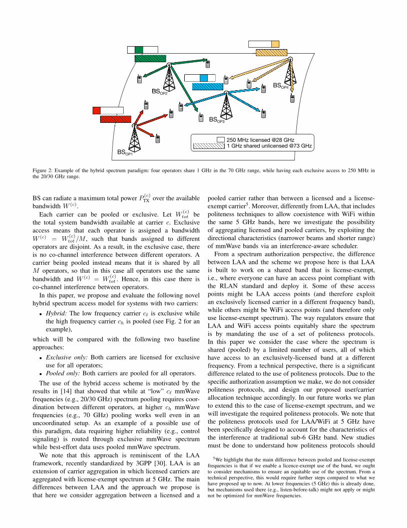
We provide a graphical representation of the implications ofthe different configurations on the transmit beams in Figure 3,and summarize the parameters for the different configurationsin Table III. Configuration i) implies that the same beamwidthis used for the two bands. Moreover, due to the increased pathloss at higher frequencies, the higher band provides a reducedcoverage area. Configuration ii) implies that a narrower beamis used for the higher frequency. However, EIRP normalizationat the higher frequency implies that also in this case thehigher frequency might provide a reduced coverage area.Configuration iii) implies that a narrower beam is used for thehigher frequency. Allowing a higher EIRP for the higher bandallows an increased coverage area (which becomes similar tothat of the lower band), although the drawback is an increasedinterference to the other cells.
IV. DISTRIBUTED CELL AND CARRIER ASSOCIATION
The network performance under any spectrum access model(exclusive, pooled or hybrid) will depend on how a UE isassigned a serving BS and a carrier. This problem is called celland carrier association and can be formalized as follows. Indexthe set of all BSs by i and all UEs by j. Let Im and Jm be thesubsets of base stations and UEs for operator m7. In cell andcarrier association, each UE j must be assigned a serving BScell i∗(j) and a carrier c∗(j). The selection (i∗(j), c∗(j)) willbe called the cell-carrier assignment. Importantly, we assumethat the UE can only be assigned a cell from its own operator’snetwork.
Although joint cell and carrier assignment has been dis-cussed extensively in the past, most works in this area havefocused on macro/pico user association [46]–[48], whereas ref-erence [49] considers user association in multi-carrier settings.All these works perform a “one-shot” optimization where allUEs are reallocated together.
7Note that Jm represents the set of users for operator m, while Jm standsfor their number, so Jm = |Jm|, ∀m ∈M. The same concept is also usedfor operators and BSs, thus Im = |Im| and M = |M|.
# UE antenna
elements
# BS antenna
elements
BS Power limit
PTX [dBm]
28 GHz 73 GHz 28 GHz 73 GHz 28 GHz 73 GHz
i) 16 16 64 64 30 30
ii) 16 64 64 256 30 24
iii) 16 64 64 256 30 30
Table III: Antenna element sizes and transmit power limits for the various power constraints.
!"#$%& '(#$%&
Figure 3: Examples of beamforming and coverage in the two bands for the three power constraint scenarios. The left drawing is case i), the one in the middleis constraint ii) and finally, the right drawing is case iii).
Unlike in these related papers, here we consider the fol-lowing simple distributed method: each new UE decides aninitial cell-carrier assignment when it enters connected modein the network. We consider an uncoordinated approach whereeach UE that joins the network receives status informationfrom the BSs that it can reach and then makes the associationdecision. We observe that the proposed distributed schemesdo not require any major changes to the signaling proceduresof today’s systems. Moreover, they do not require exchangeof information among the BSs. The amount of informationexchanged is limited to the load of the carrier’s BS andthe channel of the link for the two carriers. The downlinkSINR values γ(c)ij can be determined from measurement reportsexchanged (assuming they account for the beamforming gain)and the load information is received from the pool of candidatebase stations. Then, the cell-carrier assignment is chosen toensure the desired rate and provide load balancing in thenetwork.
To perform the cell-carrier assignment, we consider twopossible greedy heuristics:
• Load-aware joint carrier and cell association. In thiscase, the UE jointly selects the serving BS and the carrierso as to maximize its rate without considering the effectof this choice on the other UEs. Specifically, the UEselects the cell-carrier assignment via the maximization.
(c∗, i∗) = arg maxi∈Im,c∈C
(W (c)
1 +N(c)i
log2
(1 + γ
(c)ij
)),
(10)where N
(c)i is the number of UEs already associated
to the c-th carrier of the i-th base station; W (c) is thebandwidth of the c-th carrier, and γ
(c)ij is the SINR
between UE j and BS i if allocated to carrier c, given inEq. (3) which includes the spatial channel characteristicsand beamforming directions. For pooled carriers, it willalso include the interference from other operators in the
same band. We let ηj denote the resulting maximum ratefor the UE:
ηj =W (c∗)
1 +N(c∗)i∗
log2
(1 + γ
(c∗)i∗j
). (11)
When computing the rate ηj , we split the bandwidthamong all the users associated to the BS even if duringthe simulation we allocate the entire bandwidth to a singleUE at a time. Furthermore, with this procedure, the ratiobetween the total bandwidth W (c) and the number ofusers (1+N
(c)mi ) associated to the specific carrier provides
the average amount of resources allocated to the j-th userover time.
• Load-aware carrier-only association. BS and carrier se-lection are decoupled, i.e., the UE allocation to theserving BS is kept fixed for the entire simulation, whilethe UE is allowed to select only the carrier as a functionof the load and of the SINR. That is, the carrier is updatedvia
(c∗) = arg maxc∈C
(W (c)
1 +N(c)i∗
log2
(1 + γ
(c)i∗j
)), (12)
where, instead of trying all the possible BSs i ∈ Im,the algorithm is constrained to keep the current BS i,i.e., i ≡ i∗, and only optimizes the choice of the carrierc ∈ C.
Both these greedy procedures are computable with theknowledge of load and channel state conditions that areobtained from N
(c)i and γ(c)i∗j , respectively.
A. Observations and Extensions
The distributed approach described above results in alightweight implementation that enables responsiveness torapid fluctuations of the channel state and traffic conditions.Nonetheless, relying on distributed rate optimization may lead
0 1000 2000 3000 4000 5000Steps
0.48
0.5
0.52
0.54
0.56
0.58
0.6
0.62
0.64
0.66A
ssocia
tion p
robabili
ty
30 BSs/km2
60 BSs/km2
90 BSs/km2
120 BSs/km2
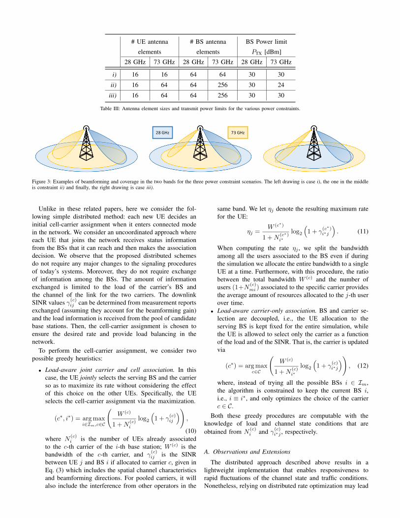
Figure 4: Example of the convergence for the probability that a user isassociated to carrier c` = 28 GHz. Here reported is a run for hybrid case i).The algorithm is initialized with a 0.5 value for each carrier and convergesto a stable value which depends on the BS density.
to sub-optimal solutions. Conversely, a centralized frameworkcan generate optimal solutions, but the excessive control sig-naling may affect the responsiveness to channel and traffic dy-namics. The performance gap between distributed approachesand a centralized implementation will be the objective of ourfuture work.
We also note that the approaches in Equations (10) and (12)assume a round-robin scheduling. However, the results can beeasily extended to a proportionally fair scheduler, by capturingthe effect of different UE rates.
B. Cell and carrier selection simulation
In the simulation, we use a methodology to evaluate thesteady-state behavior of the network. More precisely, weimplement an iterative procedure (described in the following)which converges to the long-term load distribution betweenthe two carriers achieved in the hybrid scheme.
In the first phase of the simulation, conditioned on allchannel gains, each UE j ∈ Jm in the area is associatedto the BS i ∈ Im with the highest signal strength. Notethat the choice of BS i is not random but instead based onminimum path loss and so, given the shadowing conditions,deterministic. After the selection of the best BS, we randomlyassociate the UE to the BS band at c` or ch, according to somefixed probabilities Pc` and Pch = 1−Pc` . In this study, theseinitial assignment probabilities are taken equal to 1
2 .In the second phase of the simulation, we iteratively update
the cell-carrier assignment by randomly picking one UE at atime (referred to in the following as UE j). For the selected UEj, we update its cell and carrier using (10) or only its carrierusing (12). We repeat this iterative procedure by re-allocatinga random UE at each step, until convergence to a point isreached. We use the numerical results of Figure 4 to quantifythe convergence point and, using this method, we can identifythe percentage of users that are connected to c` or ch. We notethat (cf. Figure 4) the probability that a user is associated to
0 10 20 30 40# of UEs
0
0.1
0.2
0.3
0.4
0.5
0.6
0.7
0.8
0.9
1
Em
piric
al C
DF
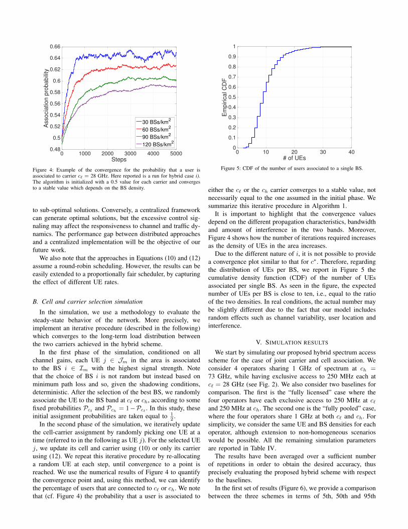
Figure 5: CDF of the number of users associated to a single BS.
either the c` or the ch carrier converges to a stable value, notnecessarily equal to the one assumed in the initial phase. Wesummarize this iterative procedure in Algorithm 1.
It is important to highlight that the convergence valuesdepend on the different propagation characteristics, bandwidthand amount of interference in the two bands. Moreover,Figure 4 shows how the number of iterations required increasesas the density of UEs in the area increases.
Due to the different nature of i, it is not possible to providea convergence plot similar to that for c∗. Therefore, regardingthe distribution of UEs per BS, we report in Figure 5 thecumulative density function (CDF) of the number of UEsassociated per single BS. As seen in the figure, the expectednumber of UEs per BS is close to ten, i.e., equal to the ratioof the two densities. In real conditions, the actual number maybe slightly different due to the fact that our model includesrandom effects such as channel variability, user location andinterference.
V. SIMULATION RESULTS
We start by simulating our proposed hybrid spectrum accessscheme for the case of joint carrier and cell association. Weconsider 4 operators sharing 1 GHz of spectrum at ch =73 GHz, while having exclusive access to 250 MHz each atc` = 28 GHz (see Fig. 2). We also consider two baselines forcomparison. The first is the “fully licensed” case where thefour operators have each exclusive access to 250 MHz at c`and 250 MHz at ch. The second one is the “fully pooled” case,where the four operators share 1 GHz at both c` and ch. Forsimplicity, we consider the same UE and BS densities for eachoperator, although extension to non-homogeneous scenarioswould be possible. All the remaining simulation parametersare reported in Table IV.
The results have been averaged over a sufficient numberof repetitions in order to obtain the desired accuracy, thusprecisely evaluating the proposed hybrid scheme with respectto the baselines.
In the first set of results (Figure 6), we provide a comparisonbetween the three schemes in terms of 5th, 50th and 95th
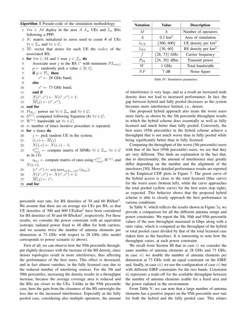
Algorithm 1 Pseudo-code of the simulation methodology
1: ∀m ∈ M deploy in the area A Jm UEs and Im BSsfollowing a PPP;
2: N : matrix initialized to zeros used to count # of UEs∀i ∈ Im and ∀c ∈ C;
3: M : vector that stores for each UE the index of theassociated BS;
4: for ∀m ∈M and ∀ user j ∈ Jm do5: Associate user j to the BS i∗ with minimum PLmij ;6: p← randomly pick a value ∈ [0, 1];7: if p < Pc` then8: c∗ ← 28 GHz band;9: else
10: c∗ ← 73 GHz band;11: end if12: N(i∗, c∗)← N(i∗, c∗) + 1;13: M(j)← (i∗, c∗);14: end for15: PTXic
: power set ∀i ∈ Im and ∀c ∈ C;16: G(c): computed following Equation (8) ∀c ∈ C;17: W (c): bandwidth set ∀c ∈ C;18: n: number of times iterative procedure is repeated;19: for n times do20: j ← pick random UE in the system;21: (i, c)←M(j)22: N(i, c)← N(i, c)− 1;23: γ
(c)mij ← compute matrix of SINRs ∀i ∈ Im, ∀c ∈ C
as in (3);24: ηmj ← compute matrix of rates using γ(c)mij , W (c), and
N(i, c);25: (c∗, i∗)← arg maxi∈Im,c∈C (ηmj);26: N(i∗, c∗)← N(i∗, c∗) + 1;27: M(j)← i∗;28: end for
percentile user rate, for BS densities of 30 and 60 BS/km2.We assume that there are on average ten UEs per BS, so thatUE densities of 300 and 600 UEs/km2 have been consideredfor BS densities of 30 and 60 BSs/km2, respectively. For theseresults, we consider the power constraint with an equivalentisotropic radiated power fixed to 48 dBm for both carriers,and we assume twice the number of antenna elements perdimension at 73 GHz with respect to 28 GHz (this modelcorresponds to power scenario ii) above).
First of all, we can observe how the 95th percentile through-put slightly decreases with the increase of the BS density, sincedenser topologies result in more interference, thus affectingthe performance of the best users. This effect is decreased,and in fact almost vanishes, in the fully licensed case due tothe reduced number of interfering sources. For the 5th and50th percentiles, increasing the density results in a throughputincrease, because the average coverage area is reduced andthe BSs are closer to the UEs. Unlike in the 95th percentilecase, here the gain from the closeness of the BS outweighs theloss due to the increased interference. Especially in the fullypooled case, considering also multiple operators, the amount
Notation Value Description
M 4 Number of operatorsA 0.3 km2 Area of simulationλUE {300, 600} UE density per km2
λBS {30, 60} BS density per km2
f {28, 73} GHz Carrier frequencyPTX {24, 30} dBm Transmit powerW 1 GHz Total bandwidthNF 7 dB Noise figure
Table IV: Simulation parameters.
of interference is very large, and as a result an increased nodedensity does not lead to increased performance. In fact, thegap between hybrid and fully pooled decreases as the systembecomes more interference limited, i.e., denser.
Our proposed hybrid approach also treats the worst usersmore fairly, as shown by the 5th percentile throughput resultsin which the hybrid scheme does essentially as well as fullylicensed and much better than fully pooled. Conversely, thebest users (95th percentile) in the hybrid scheme achieve athroughput that is not much worse than in fully pooled whilebeing significantly better than in fully licensed.
Comparing the throughput of the worst (5th percentile) userswith that of the best (95th percentile) users, we see that theyare very different. This finds an explanation in the fact that,due to directionality, the amount of interference may greatlydiffer depending on the number and the alignment of theinterferers [50]. More detailed performance results are reportedin the Empirical CDF plots in Figure 7. The green curve ofthe hybrid access is close to the total licensed (blue curve)for the worst users (bottom left), while the curve approachesthe total pooled (yellow curve) for the best users (top right),as expected. This behavior shows that the proposed hybridscheme is able to closely approach the best performance invarious conditions.
In Table V, which reflects the results shown in Figure 7a, weprovide a comparison for all the different antenna setups andpower constraints. We report the 5th, 50th and 95th percentilevalues of the user throughput measured in Gbps along with aratio value, which is computed as the throughput of the hybridor total pooled cases divided by that of the total licensed case(taken here as the baseline). It is interesting to note how thethroughput varies, at each power constraint.
We recall from Section III that in case i) we consider thesame number of antenna elements at 28 GHz and 73 GHz,in case ii) we double the number of antenna elements perdimension at 73 GHz with an equal constraint on the EIRP,and, finally, in case iii) we use the configuration of case ii) butwith different EIRP constraints for the two bands. Constraintii) represents a trade-off for the available throughput betweenthe number of antenna elements usable for a fixed area andthe power radiated in the environment.
From Table V, we can note that a large number of antennaelements has a positive impact on the 95th percentile user ratefor both the hybrid and the fully pooled case. This relates

5 50 95 Percentile
0
0.5
1
1.5
2
2.5
3T
hro
ug
hp
ut
pe
r U
E [
Gb
ps]
Power constraint ii)
fully licensedhybridfully pooled
(a) Case with BS density equal to 30 BSs/km2.
5 50 95 Percentile
0
0.5
1
1.5
2
2.5
3
Th
rou
gh
pu
t p
er
UE
[G
bp
s]
Power constraint ii)
fully licensedhybridfully pooled
(b) Case with BS density equal to 60 BSs/km2.
Figure 6: Comparison of the throughput measured for the hybrid case and the two baselines. Empirical CDF values of the throughput for the 5th, 50th and95th percentiles in the power constraint case ii).
0 1 2 3 4 5 6Throughput per UE [Gbps]
0
0.2
0.4
0.6
0.8
1
Em
piric
al C
DF
Power constraint ii)
fully licensedhybridfully pooled
(a) Case with BS density equal to 30 BSs/km2.
0 1 2 3 4 5 6Throughput per UE [Gbps]
0
0.2
0.4
0.6
0.8
1
Em
piric
al C
DF
Power constraint ii)
fully licensedhybridfully pooled
(b) Case with BS density equal to 60 BSs/km2.
Figure 7: Comparison of the throughput measured for the hybrid case and the two baselines. Empirical CDF curves of the throughput for the power constraintcase ii).
Power constraint i) Power constraint ii) Power constraint iii)Value Ratio Value Ratio Value Ratio
Fully licensed 5% 0.0328 1.00 0.0362 1.00 0.0674 1.00Hybrid 5% 0.0147 0.45 0.0190 0.52 0.0265 0.39Fully pooled 5% 0.0003 0.0091 0.0007 0.019 0.0007 0.010
Fully licensed 50% 0.3455 1.00 0.3848 1.00 0.4176 1.00Hybrid 50% 0.3736 1.08 0.4492 1.17 0.5081 1.22Fully pooled 50% 0.3143 0.91 0.4795 1.25 0.4878 1.17
Fully licensed 95% 0.9188 1.00 1.0770 1.00 1.0218 1.00Hybrid 95% 1.9194 2.09 2.1810 2.03 2.0252 1.98Fully pooled 95% 2.1926 2.39 2.6970 2.49 2.5461 2.49
Table V: Values of the throughput (measured in Gbps) for the hybrid case and the two baselines. Rates for the 5th, 50th and 95th percentiles and all thepower constraints, simulations with a BS density of 30 BSs/km2. The ratio values are computed as the throughput of the hybrid or total pooled cases dividedby that of the total licensed case, which is taken as a reference.
to coverage, along with the amount of interference generatedwithin the cell: using more antennas results in narrower beams,and hence reduced interference, which in turn leads to higher
throughput. Further, by looking at the ratio values reportedin Table V, we can better understand the performance gainsobtained with a hybrid scheme vs. a total pooled spectrum

-40 -20 0 20 40 60 80SINR [dB]
0
0.2
0.4
0.6
0.8
1E
mpiric
al C
DF
fully licensedhybridfully pooled
Figure 8: Comparison of the SINR measured for the hybrid case and thetwo baselines. Empirical CDF for the power constraint case ii) and with BSdensity equal to 60 BSs/km2.
access. In the more realistic scenario, i.e., power constraint ii),the 5% user throughput of the hybrid case is smaller than thatobtained via a fully licensed scheme (about 50% smaller), andon the other hand much higher than the rate achieved witha total pooled approach (about 32 times higher). A similarbehavior is observed for all the power configurations at the 5thpercentile, while the opposite occurs if we consider the 95%user throughput. This last behavior is less pronounced and forthis reason we can conclude that our hybrid procedure exhibitsdesirable performance, and represents a tradeoff between thetwo baselines. This is due to the fairness that originates fromour opportunistic carrier selection.
We also show in Figure 8 the Empirical CDF of the SINRfor the hybrid spectrum access scheme and the two baselinesfully licensed and fully pooled. When bandwidth sharing isincreased, the average SINR decreases and the CDF curvemoves to the left. However, it is important to highlight thatour approach does not have the goal of optimizing the SINRbut rather tries to maximize the user rate, considering alsothe load in terms of UEs connected to the BS, which is notconsidered in Fig. 8.
We present a further evaluation in Figure 9, aiming to assessthe performance impact of different available bandwidths (1,3 and 5 GHz) for the ch frequency carrier. Once again, thehybrid scheme exhibits similar trends as in the fully licensedcase for the worst users, while approaching the fully pooledcase performance gains for the best users. Even if the thermalnoise and the interference increase with larger bandwidth,improvements in the throughput are observed in each scenariowhen the band increases. Moreover, the gap between thehybrid and total pooled schemes is reduced when the totalbandwidth used at 73 GHz is increased.
Finally, we report in Figure 10 a comparison between thedifferent association algorithms, where each UE either jointlyselects the serving BS and the frequency band (left plot), orcan only choose the optimal carrier while keeping the BSassociation fixed (right plot). From these results, we can ob-serve that the throughput provided by carrier-only association
is higher than by joint association for the best users (95thpercentile), while the opposite occurs for the median and worst(5th percentile) users. This can be explained by observing thatin the carrier-only association it is not possible to redistributeusers to balance the load among BSs, and therefore the bestusers are likely to be those that happen to be associated tolightly loaded BSs, enjoying a higher rate compared to whatthey would achieve under the joint cell and carrier association.For the same reason, the worst users (likely associated tohighly loaded BSs) experience very poor performance. On thecontrary, joint cell and carrier association tends to distributeusers among BSs and carriers more equitably, and results in afairer system.
VI. CONCLUSION AND FUTURE WORKS
In this paper, we have introduced a new hybrid spectrumaccess scheme for mmWave networks, where data packetsare scheduled through two mmWave carriers with differentcharacteristics. In particular, we have proposed a spectrumsharing scheme which combines a lower mmWave band withexclusive access and a higher mmWave band where spectrumis pooled between multiple operators. Our investigation showsthat this approach provides advantages for the average userwith respect to traditional fully licensed or fully pooledspectrum access schemes, in terms of increased throughput andspectral efficiency. The approach offers also better balancingof the available resources with respect to the fully pooled case,resulting in higher fairness. This work opens a promising lineof research towards a more flexible and efficient use of theradio spectrum, and will provide useful input and insights tostandardization and spectrum policy.
However, further work is needed to reach a more completeunderstanding of different aspects. First, the study in this paperconsiders the case where the higher mmWave band is pooledbetween multiple operators all having a licensed anchor inanother mmWave band at a lower frequency. It would beinteresting to study a more general spectrum arrangementwhere the higher mmWave band is entirely license-exempt,i.e., can be accessed by heterogeneous users with and withoutan anchor at a lower frequency. The main challenge in thiscase is how to design politeness mechanisms in a very direc-tional propagation environment. On one side traditional listen-before-talk techniques would not provide a reliable solution.On the other side, more recent directional MAC approachesintroduced for 802.11ad (that is based on fully unlicensedspectrum access) would be suboptimal in a hybrid mmWavespectrum context. Second, our study is based on a distributeduncoordinated algorithm. We chose this approach because itallows an initial assessment based on a practical mechanismthat has a low impact on signaling and architecture design.On the other hand, we believe that centralized approachescould also provide a realistic solution, in particular in networkswhere infrastructure sharing is used. Third, while this studyprovides an initial, proof-of-concept assessment based onsimulation, we believe that a mathematical analysis could leadto a more fundamental understanding of the different factorsunderlying hybrid spectrum access. Finally, it would also be
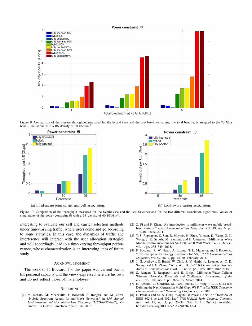
1 3 5 Total bandwidth at 73 GHz [GHz]
0
1
2
3
4
5
6
7
Th
rou
gh
pu
t p
er
UE
[G
bp
s]
Power constraint ii)
fully licensed 5%hybrid 5%fully pooled 5%fully licensed 50%hybrid 50%fully pooled 50%fully licensed 95%hybrid 95%fully pooled 95%
Figure 9: Comparison of the average throughput measured for the hybrid case and the two baselines varying the total bandwidth assigned to the 73 GHzband. Simulations with a BS density of 60 BSs/km2.
5 50 95 Percentile
0
0.5
1
1.5
2
2.5
3
Th
rou
gh
pu
t p
er
UE
[G
bp
s]
Power constraint ii)
fully licensedhybridfully pooled
(a) Load-aware joint carrier and cell association.
5 50 95 Percentile
0
0.5
1
1.5
2
2.5
3
Thro
ughput per
UE
[G
bps]
Power constraint ii)
fully licensedhybridfully pooled
(b) Load-aware carrier association.
Figure 10: Comparison of the throughput measured for the hybrid case and the two baselines and for the two different association algorithms. Values ofsimulations of the power constraint ii) with a BS density of 60 BSs/km2.
interesting to evaluate our cell and carrier selection methodsunder time-varying traffic, where users come and go accordingto some statistics. In this case, the dynamics of traffic andinterference will interact with the user allocation strategiesand will accordingly lead to a time-varying throughput perfor-mance, whose characterization is an interesting item of futurestudy.
ACKNOWLEDGMENT
The work of F. Boccardi for this paper was carried out inhis personal capacity and the views expressed here are his ownand do not reflect those of his employer
REFERENCES
[1] M. Rebato, M. Mezzavilla, F. Boccardi, S. Rangan, and M. Zorzi,“Hybrid Spectrum Access for mmWave Networks,” in 15th AnnualMediterranean Ad Hoc Networking Workshop (MED-HOC-NET), Vi-lanova i la Geltru, Barcelona, Spain, Jun. 2016.
[2] Z. Pi and F. Khan, “An introduction to millimeter-wave mobile broad-band systems,” IEEE Communications Magazine, vol. 49, no. 6, pp.101–107, June 2011.
[3] T. S. Rappaport, S. Sun, R. Mayzus, H. Zhao, Y. Azar, K. Wang, G. N.Wong, J. K. Schulz, M. Samimi, and F. Gutierrez, “Millimeter WaveMobile Communications for 5G Cellular: It Will Work!” IEEE Access,vol. 1, pp. 335–349, 2013.
[4] F. Boccardi, R. W. Heath, A. Lozano, T. L. Marzetta, and P. Popovski,“Five disruptive technology directions for 5G,” IEEE CommunicationsMagazine, vol. 52, no. 2, pp. 74–80, February 2014.
[5] J. G. Andrews, S. Buzzi, W. Choi, S. V. Hanly, A. Lozano, A. C. K.Soong, and J. C. Zhang, “What Will 5G Be?” IEEE Journal on SelectedAreas in Communications, vol. 32, no. 6, pp. 1065–1082, June 2014.
[6] S. Rangan, T. Rappaport, and E. Erkip, “Millimeter-Wave CellularWireless Networks: Potentials and Challenges,” Proceedings of theIEEE, vol. 102, no. 3, pp. 366–385, March 2014.
[7] E. Perahia, C. Cordeiro, M. Park, and L. L. Yang, “IEEE 802.11ad:Defining the Next Generation Multi-Gbps Wi-Fi,” in 7th IEEE ConsumerCommunications and Networking Conference, Jan 2010.
[8] E. Perahia and M. X. Gong, “Gigabit Wireless LANs: An Overview ofIEEE 802.11ac and 802.11ad,” SIGMOBILE Mob. Comput. Commun.Rev., vol. 15, no. 3, pp. 23–33, Nov. 2011. [Online]. Available:http://doi.acm.org/10.1145/2073290.2073294

[9] W. Roh, J. Y. Seol, J. Park, B. Lee, J. Lee, Y. Kim, J. Cho, K. Cheun, andF. Aryanfar, “Millimeter-wave beamforming as an enabling technologyfor 5G cellular communications: theoretical feasibility and prototyperesults,” IEEE Communications Magazine, vol. 52, no. 2, pp. 106–113,February 2014.
[10] T. S. Rappaport, R. W. Heath Jr., R. C. Daniels, and J. N. Murdock,Millimeter Wave Wireless Communications. Pearson Education, 2014.
[11] A. Osseiran, F. Boccardi, V. Braun, K. Kusume, P. Marsch, M. Maternia,O. Queseth, M. Schellmann, H. Schotten, H. Taoka, H. Tullberg, M. A.Uusitalo, B. Timus, and M. Fallgren, “Scenarios for 5G mobile andwireless communications: the vision of the METIS project,” IEEECommunications Magazine, vol. 52, no. 5, pp. 26–35, May 2014.
[12] NGMN Alliance, “5G white paper,” Next Generation Mobile Networks,White paper, February 2015.
[13] F. Guidolin, M. Nekovee, L. Badia, and M. Zorzi, “A study on thecoexistence of fixed satellite service and cellular networks in a mmWavescenario,” in IEEE International Conference on Communications (ICC),Jun 2015, pp. 2444–2449.
[14] F. Boccardi, H. Shokri-Ghadikolaei, G. Fodor, E. Erkip, C. Fischione,M. Kountouris, P. Popovski, and M. Zorzi, “Spectrum Pooling inMmWave Networks: Opportunities, Challenges, and Enablers,” IEEECommunications Magazine, vol. 54, no. 11, pp. 33–39, November 2016.
[15] F. Gomez-Cuba, S. Rangan, and E. Erkip, “Scaling Laws for Infrastruc-ture Single and Multihop Wireless Networks in Wideband Regimes,”in IEEE International Symposium on Information Theory (ISIT), June2014, pp. 76–80.
[16] M. Rebato, M. Mezzavilla, S. Rangan, F. Boccardi, and M. Zorzi,“Understanding Noise and Interference Regimes in 5G Millimeter-WaveCellular Networks,” in 22th European Wireless Conference, May 2016.
[17] A. Ghosh, T. A. Thomas, M. C. Cudak, R. Ratasuk, P. Moorut,F. W. Vook, T. S. Rappaport, G. R. MacCartney, S. Sun, and S. Nie,“Millimeter-wave enhanced local area systems: A high-data-rate ap-proach for future wireless networks,” IEEE Journal on Selected Areasin Communications, vol. 32, no. 6, pp. 1152–1163, June 2014.
[18] J. G. Andrews, “Seven ways that HetNets are a cellular paradigm shift,”IEEE Communications Magazine, vol. 51, no. 3, pp. 136–144, March2013.
[19] H. Ishii, Y. Kishiyama, and H. Takahashi, “A novel architecture for LTE-B: C-plane/U-plane split and Phantom Cell concept,” in IEEE GlobecomWorkshops, Dec 2012, pp. 624–630.
[20] H. Elshaer, M. N. Kulkarni, F. Boccardi, J. G. Andrews, and M. Dohler,“Downlink and Uplink Cell Association with Traditional Macrocellsand Millimeter Wave Small Cells,” IEEE Transactions on WirelessCommunications, vol. 15, no. 9, pp. 6244–6258, Sept 2016.
[21] ITU-R, “Final acts WRC-15,” Tech. Rep., Dec. 2015.[22] T. A. Weiss and F. K. Jondral, “Spectrum pooling: an innovative strategy
for the enhancement of spectrum efficiency,” IEEE CommunicationsMagazine, vol. 42, no. 3, pp. S8–14, Mar 2004.
[23] METIS, “Deliverable 5.1, intermediate description of spectrum needsand usage principles,” Tech. Rep., 2013.
[24] T. Irnich, J. Kronander, Y. Seln, and G. Li, “Spectrum sharing sce-narios and resulting technical requirements for 5G systems,” in IEEE24th International Symposium on Personal, Indoor and Mobile RadioCommunications (PIMRC Workshops), Sept 2013, pp. 127–132.
[25] A. K. Gupta, A. Alkhateeb, J. G. Andrews, and R. W. Heath, “Gainsof restricted secondary licensing in millimeter wave cellular systems,”IEEE Journal on Selected Areas in Communications, vol. 34, no. 11,pp. 2935–2950, Nov 2016.
[26] H. A. Safavi-Naeini, S. Roy, and S. Ashrafi, “Spectrum Sharing ofRadar and Wi-Fi Networks: The Sensing/Throughput Tradeoff,” IEEETransactions on Cognitive Communications and Networking, vol. 1,no. 4, pp. 372–382, Dec 2015.
[27] G. Zheng and Q. Guan, “Routing and spectrum sharing in geo-locationdatabase assisted secondary multi-hop networks,” in IEEE InternationalConference on Communications (ICC), June 2014, pp. 1669–1674.
[28] M. Matinmikko, H. Okkonen, M. Palola, S. Yrjola, P. Ahokangas, andM. Mustonen, “Spectrum sharing using licensed shared access: theconcept and its workflow for lte-advanced networks,” IEEE WirelessCommunications, vol. 21, no. 2, pp. 72–79, April 2014.
[29] S. Bhattarai, J. M. J. Park, B. Gao, K. Bian, and W. Lehr, “An Overviewof Dynamic Spectrum Sharing: Ongoing Initiatives, Challenges, anda Roadmap for Future Research,” IEEE Transactions on CognitiveCommunications and Networking, vol. 2, no. 2, pp. 110–128, June 2016.
[30] 3GPP TR 36.889 v1.0.1, “Study on licensed-assisted access to unli-censed spectrum,” Tech. Rep., 2015.
[31] A. Mukherjee, J. F. Cheng, S. Falahati, H. Koorapaty, D. H. Kang,R. Karaki, L. Falconetti, and D. Larsson, “Licensed-Assisted Access
LTE: coexistence with IEEE 802.11 and the evolution toward 5G,” IEEECommunications Magazine, vol. 54, no. 6, pp. 50–57, June 2016.
[32] F. M. Abinader, E. P. L. Almeida, F. S. Chaves, A. M. Cavalcante, R. D.Vieira, R. C. D. Paiva, A. M. Sobrinho, S. Choudhury, E. Tuomaala,K. Doppler, and V. A. Sousa, “Enabling the coexistence of LTE andWi-Fi in unlicensed bands,” IEEE Communications Magazine, vol. 52,no. 11, pp. 54–61, Nov 2014.
[33] 3GPP, “Liaison from 3GPP on LWA and LWIP,” Tech. Rep., Mar 2016.[34] A. Galanopoulos, F. Foukalas, and T. A. Tsiftsis, “Efficient Coexistence
of LTE With WiFi in the Licensed and Unlicensed Spectrum Aggrega-tion,” IEEE Transactions on Cognitive Communications and Networking,vol. 2, no. 2, pp. 129–140, June 2016.
[35] G. Li, T. Irnich, and C. Shi, “Coordination context-based spectrum shar-ing for 5G millimeter-wave networks,” in IEEE International Conferenceon Cognitive Radio Oriented Wireless Networks and Communications(CROWNCOM), 2014, pp. 32–38.
[36] A. K. Gupta, J. G. Andrews, and R. W. Heath, “On the Feasibilityof Sharing Spectrum Licenses in mmWave Cellular systems,” IEEETransactions on Communications, vol. 64, no. 9, pp. 3981–3995, Sept2016.
[37] M. Rebato, M. Mezzavilla, S. Rangan, and M. Zorzi, “Resource Sharingin 5G mmWave Cellular Networks,” in IEEE INFOCOM Millimeter-wave Networking Workshop (mmNet 2016), San Francisco, USA, Apr.2016.
[38] H. Shokri-Ghadikolaei, F. Boccardi, C. Fischione, G. Fodor, andM. Zorzi, “On the value of Beamforming and Coordination for SpectrumSharing in mmWave Cellular Networks,” IEEE Journal on SelectedAreas in Communications, vol. 34, no. 11, pp. 2902–2917, Nov 2016.
[39] F. Fund, S. Shahsavari, S. S. Panwar, E. Erkip, and S. Rangan,“Spectrum and infrastructure sharing in millimeter wave cellularnetworks: An economic perspective,” CoRR, vol. abs/1605.04602,2016. [Online]. Available: http://arxiv.org/abs/1605.04602
[40] M. Akdeniz, Y. Liu, M. Samimi, S. Sun, S. Rangan, T. Rappaport, andE. Erkip, “Millimeter Wave Channel Modeling and Cellular Capac-ity Evaluation,” IEEE Journal on Selected Areas in Communications,vol. 32, no. 6, pp. 1164–1179, June 2014.
[41] Y. Azar, G. Wong, K. Wang, R. Mayzus, J. Schulz, H. Zhao, F. Gutierrez,D. Hwang, and T. Rappaport, “28 GHz Propagation Measurements forOutdoor Cellular Communications Using Steerable Beam Antennas inNew York City,” in IEEE International Conference on Communications(ICC), June 2013, pp. 5143–5147.
[42] H. Zhao, R. Mayzus, S. Sun, M. Samimi, J. Schulz, Y. Azar, K. Wang,G. Wong, F. Gutierrez, and T. Rappaport, “28 GHz Millimeter WaveCellular Communication Measurements for Reflection and PenetrationLoss in and Around Buildings in New York City,” in IEEE InternationalConference on Communications (ICC), June 2013, pp. 5163–5167.
[43] M. Samimi, K. Wang, Y. Azar, G. Wong, R. Mayzus, H. Zhao, J. Schulz,S. Sun, F. Gutierrez, and T. Rappaport, “28 GHz Angle of Arrivaland Angle of Departure Analysis for Outdoor Cellular CommunicationsUsing Steerable Beam Antennas in New York City,” in IEEE 77thVehicular Technology Conference (VTC Spring), June 2013.
[44] M. K. Samimi and T. S. Rappaport, “3-D statistical channel model formillimeter-wave outdoor mobile broadband communications,” in IEEEInternational Conference on Communications (ICC), June 2015, pp.2430–2436.
[45] D. Tse and P. Viswanath, Fundamentals of Wireless Communication.New York, NY, USA: Cambridge University Press, 2005.
[46] H. Kim, G. de Veciana, X. Yang, and M. Venkatachalam, “Distributed α-optimal user association and cell load balancing in wireless networks,”IEEE/ACM Transactions on Networking, vol. 20, no. 1, pp. 177–190,Feb 2012.
[47] P. Coucheney, C. Touati, and B. Gaujal, “Fair and efficient user-networkassociation algorithm for multi-technology wireless networks,” in IEEEINFOCOM, April 2009, pp. 2811–2815.
[48] Q. Ye, B. Rong, Y. Chen, M. Al-Shalash, C. Caramanis, and J. G.Andrews, “User association for load balancing in heterogeneous cellularnetworks,” IEEE Transactions on Wireless Communications, vol. 12,no. 6, pp. 2706–2716, June 2013.
[49] C. Kim, R. Ford, and S. Rangan, “Joint interference and user associationoptimization in cellular wireless networks,” in 48th Asilomar Conferenceon Signals, Systems and Computers, Nov 2014, pp. 511–515.
[50] M. Rebato, J. Park, P. Popovski, E. de Carvalho, and M. Zorzi, “Stochas-tic Geometric Coverage Analysis in mmWave Cellular Networks with aRealistic Channel Model,” in IEEE Global Communications Conference:Mobile and Wireless Networks (Globecom2017 MWN), Dec. 2017.


![Challenge: COSMOS: A City-Scale Programmable Testbed for ... · new system designs. It should incorporate emerging spectrum tech-niques (e.g., dynamic spectrum sharing [21ś23], mmWave](https://img.pdfslide.net/doc/110x75/5ed191cb38f837763c35f6ce/challenge-cosmos-a-city-scale-programmable-testbed-for-new-system-designs.jpg)