Embed Size (px)
Citation preview
Hybrid VRF Next Generation 2-Pipe Heat Recovery Systems
HVRF YLM Series AN2.1 - NZ
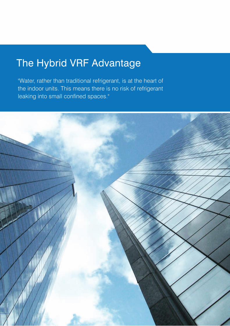
The Hybrid VRF Advantage
"Water, rather than traditional refrigerant, is at the heart of the indoor units. This means there is no risk of refrigerant leaking into small confined spaces."
2
3
Hybrid VRF is next generation technology from Mitsubishi Electric, the world leader in VRF
Solutions. This unique 2-Pipe Heat Recovery VRF System replaces refrigerant with water
between the Branch Box Controller and the indoor units. This revolutionary design removes
the need for expensive and on-going leak detection servicing and is specifically designed
for occupied spaces where quiet, energy efficient, simultaneous heating and cooling is
valued. Hybrid VRF provides a truly integrated solution for hotels, offices, hospitals and
schools where occupant comfort is paramount.
Put simply, Hybrid VRF is a 2-Pipe Heat Recovery VRF with water between the Hybrid Branch Circuit (HBC) Controller and indoor units. You can install and design it as VRF whilst enjoying the features of a chiller system. This provides a complete modern solution for office buildings, hotels, medical centres, schools, high-rise buildings, shopping centres and other commercial premises.
Hybrid VRF is quick, easy and flexible to design and install using the same control and network as VRF systems. Furthermore, the decentralised system means phased installation is possible with the same high levels of seasonal efficiency expected with VRF.
With water at the indoor units, Hybrid VRF provides comfortable and stable air temperature control with no refrigerant in occupied spaces, removing the need for leak detection.
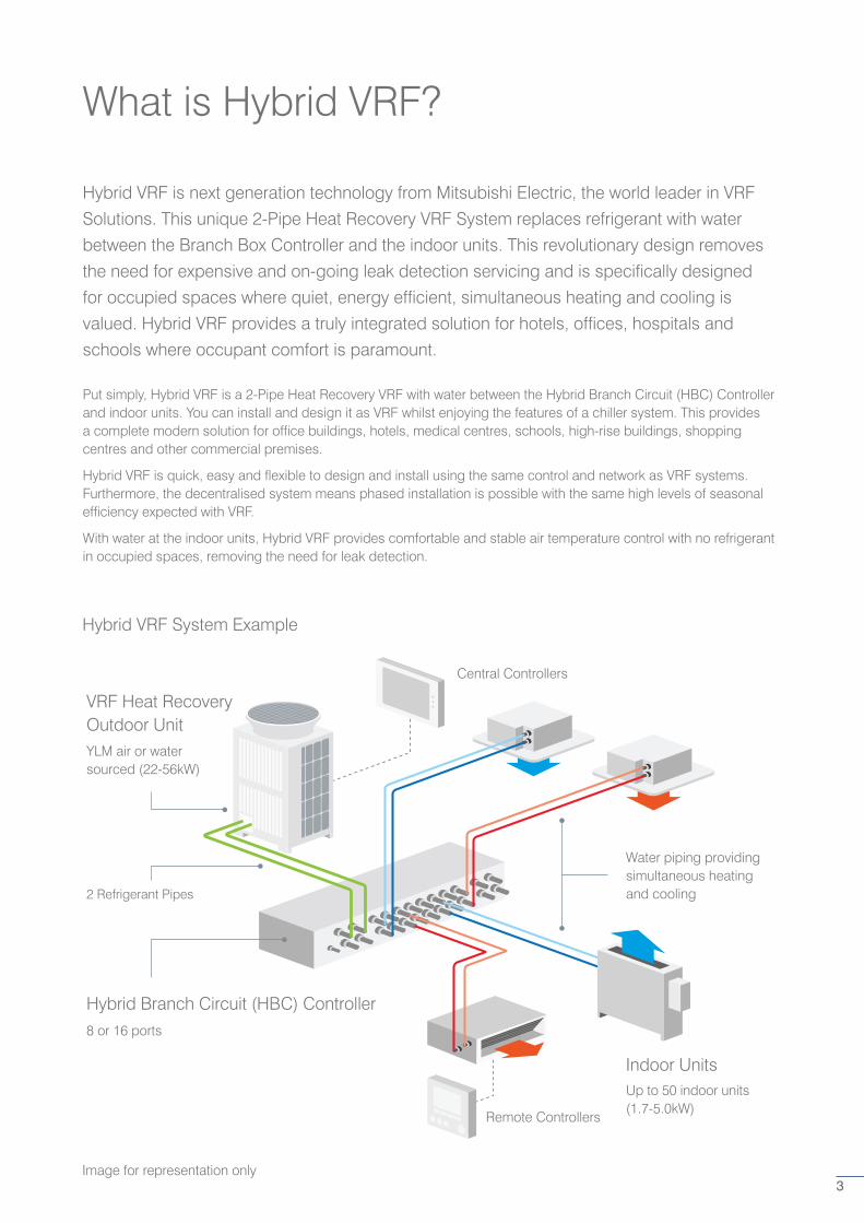
Hybrid VRF System Example
Image for representation only
2 Refrigerant Pipes
VRF Heat Recovery Outdoor Unit
Water piping providing simultaneous heating and cooling
Up to 50 indoor units (1.7-5.0kW)
Remote Controllers
Hybrid Branch Circuit (HBC) Controller
YLM air or water sourced (22-56kW)
Central Controllers
Indoor Units
8 or 16 ports
What is Hybrid VRF?

4
The Hybrid VRF Advantage
“Hybrid VRF removes the need for leak detection, reducing the total cost of the system and on-going maintenance of the leak detection systems itself.”
5
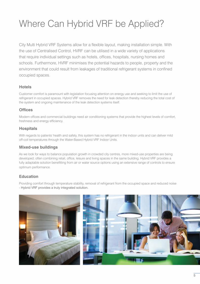
Where Can Hybrid VRF be Applied?
City Multi Hybrid VRF Systems allow for a flexible layout, making installation simple. With
the use of Centralised Control, HVRF can be utilised in a wide variety of applications
that require individual settings such as hotels, offices, hospitals, nursing homes and
schools. Furthermore, HVRF minimises the potential hazards to people, property and the
environment that could result from leakages of traditional refrigerant systems in confined
occupied spaces.
Hotels
Customer comfort is paramount with legislation focusing attention on energy use and seeking to limit the use of refrigerant in occupied spaces. Hybrid VRF removes the need for leak detection thereby reducing the total cost of the system and ongoing maintenance of the leak detection systems itself.
Offices
Modern offices and commercial buildings need air conditioning systems that provide the highest levels of comfort, freshness and energy efficiency.
Hospitals
With regards to patients' health and safety, this system has no refrigerant in the indoor units and can deliver mild off-coil temperatures through the Water-Based Hybrid VRF Indoor Units.
Mixed-use buildings
As we look for ways to balance population growth in crowded city centres, more mixed-use properties are being developed; often combining retail, office, leisure and living spaces in the same building. Hybrid VRF provides a fully adaptable solution benefitting from air or water source options using an extensive range of controls to ensure optimum performance.
Education
Providing comfort through temperature stability, removal of refrigerant from the occupied space and reduced noise - Hybrid VRF provides a truly integrated solution.
Hybrid VRF Key Features & Benefits
No Refrigerant in Occupied and Confined Spaces
• Ideal for applications where the limitation of refrigerant in occupied spaces is desired. HVRF removes the need to implement leak detection systems that would have traditionally been required in spaces such as hotel bedrooms, hospitals, nursing homes or meeting rooms.
Mitigate the Effect of Ongoing Refrigerant Cost Increases
• The NZ ETS (Emissions Trading Scheme) puts a price on greenhouse gas emissions and provides an incentive to reduce emissions and promote strategies to absorb carbon dioxide. This is known as the SGG (Synthetic Greenhouse Gas) Levy. Due to the increasing cost of refrigerant associated with ETS Synthetic Greenhouse Gas Levy (NZ), building capital costs can be higher. HVRF reduces this as it uses less refrigerant in the total system.
Energy Saving
• Save more energy by heat recovery operation if heating and cooling operations are required at the same time.
• The more frequently heating and cooling simultaneous operation occurs, the higher the energy saving effect becomes.
• Even higher efficiency operation is now possible by utilising the Centralised Control and the scheduled operation.
High Sensible Cooling and Stable Room Temperatures
• Typically 10% increase in sensible cooling vs. VRF.
• Providing superior levels of comfort.
Less Material/Equipment
• Mitsubishi Electric's unique 2-Pipe Heat Recovery System requires less pipes than a 4-Pipe Chiller System.
• The system does not require an external pump and control panel that are usually necessary for chillers.
6
Quiet Operation
• Water-Based Indoor Units: Ducted, Cassette and Concealed Floor Consoles - based on Mitsubishi Electric VRF Indoor Units.
• Low noise levels, variable airflow.
Fully Packaged Solution
• Valves, Pumps and Heat Exchangers are all contained within the HBC.
• Commissioning is simple; pipe sizes are all defined with minor third party items required.
• Uses the same controls and M-NET Network as VRF.
Flexible Application Options
• Air Source YLM (22-56kW) - using the latest City Multi VRF YLM Technology including an aluminium heat exchanger, reduced weight and improved seasonal efficiency.
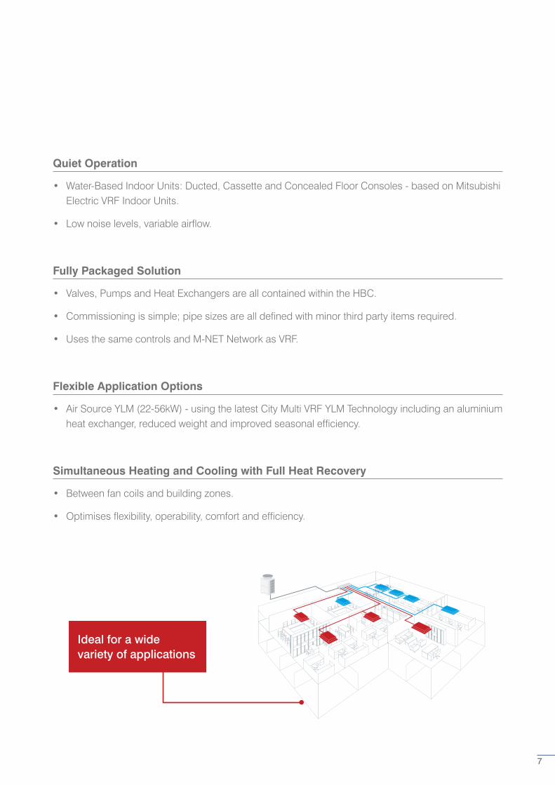
Simultaneous Heating and Cooling with Full Heat Recovery
• Between fan coils and building zones.
• Optimises flexibility, operability, comfort and efficiency.
Ideal for a wide variety of applications
7
Manageable Phased Installation
• Modular, smaller footprint and low weight outdoor units.
• Flexible range of VRF options.
Simplified 2-Pipe Design and Installation
• 2 pipes throughout system - no complex 4-pipe design.
• Flexible design using up to 50 indoor units per system over 4 Hybrid Branch Controllers.
• Copper or plastic pipe on water side.
Heat Recovery Defrost Method
• Typical defrost times of 5 minutes with immediate return to heating.
• Improving comfort throughout the heating season, ideal for office applications.
• No defrost on Water Source VRF Models.
Intuitive Load Adjusting
• The latest YLM VRF refrigerant control plus water side optimisation: flow control valves, inverter driven pumps and heat recovery.
• Providing only the capacity needed, improving efficiency and comfort.
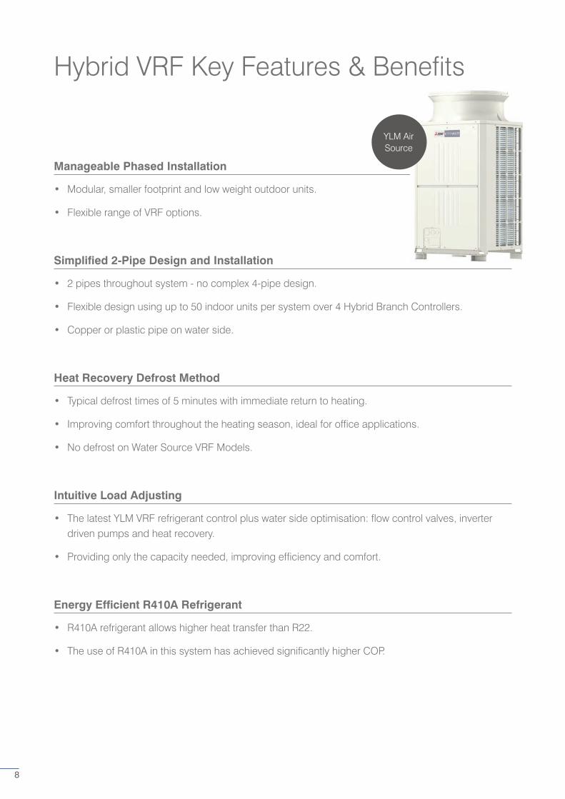
Energy Efficient R410A Refrigerant
• R410A refrigerant allows higher heat transfer than R22.
• The use of R410A in this system has achieved significantly higher COP.
YLM Air Source
Hybrid VRF Key Features & Benefits
8

Eliminate the Need for Leak Detection
$600,000 –
$450,000 –
$300,000 –
$150,000 –
$0 –Yr 1 Yr 3 Yr 5 Yr 7 Yr 9 Yr 11 Yr 13 Yr 15
Hotel Maintenance Costs* Hybrid VRF VRF + Leak Detection
In commercial buildings, additional leak detection systems specific to air conditioning are often installed to safeguard occupants due to increasing safety regulations. This affects hotels in particular, where air conditioners are installed in the room space and occupants safety is critical.
The leak detection system is designed to alarm if refrigerant was to leak into the room space and thus shut down the system to try and prevent harm to the occupants in the room space. These systems can be expensive and add to the cost of design, build and maintenance.
Hotel Solution
Hybrid VRF removes the need for leak detection in each room because there is no refrigerant piped into the room space, just water! This means there is no risk of refrigerant escaping into the room space. The Water-Based Fan Coil Units reduce draughts, improving comfort for guests, whilst providing overall savings in ongoing maintenance costs of the equipment for the hotelier.
Throughout a system’s lifetime, annual testing and the recalibration of leak detection sensors adds significant cost to a VRF system. Using Hybrid VRF instead removes this need and could provide as much as 30% in maintenance savings over 15 years.
*Based on a real project using costs from a Mitsubishi Electric Business Solutions Partner, UK.
9
10
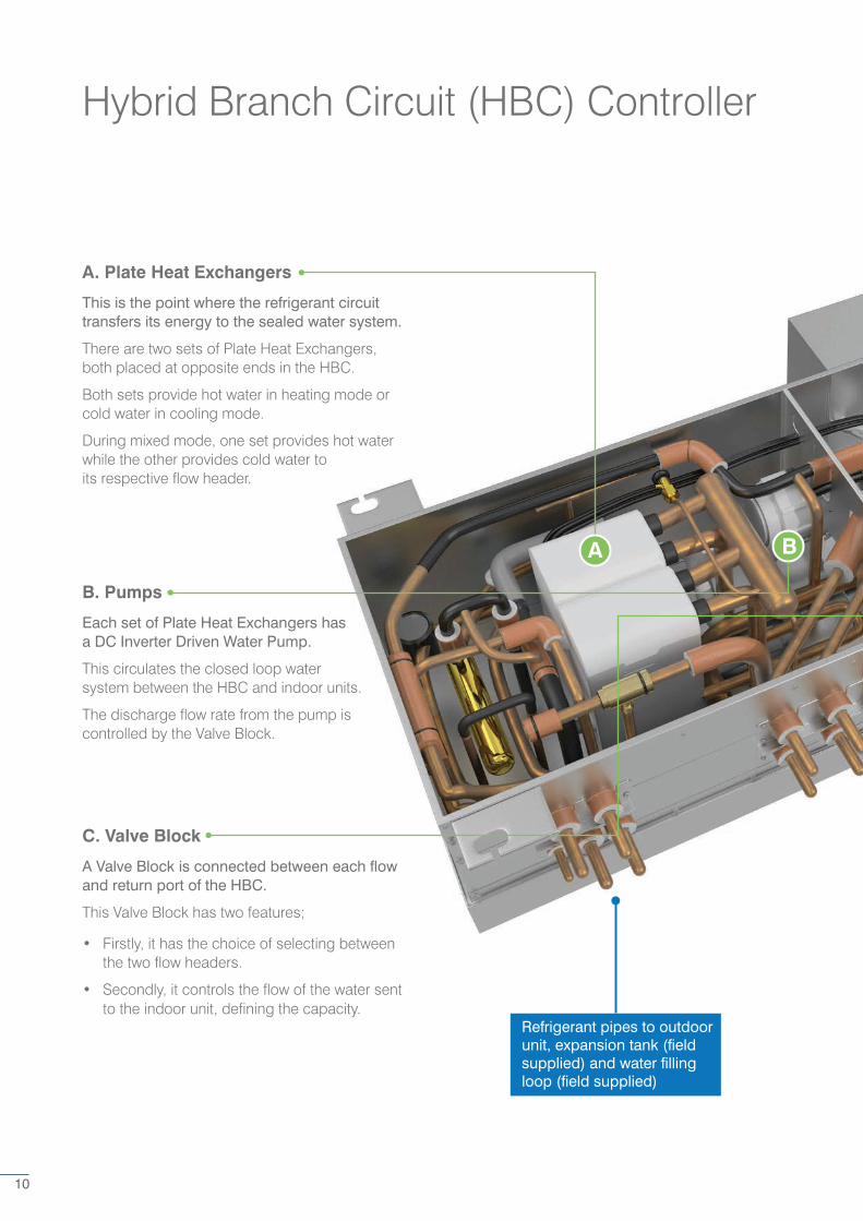
Hybrid Branch Circuit (HBC) Controller
A. Plate Heat Exchangers
This is the point where the refrigerant circuit transfers its energy to the sealed water system.
There are two sets of Plate Heat Exchangers, both placed at opposite ends in the HBC.
Both sets provide hot water in heating mode or cold water in cooling mode.
During mixed mode, one set provides hot water while the other provides cold water to its respective flow header.
B. Pumps
Each set of Plate Heat Exchangers has a DC Inverter Driven Water Pump.
This circulates the closed loop water system between the HBC and indoor units.
The discharge flow rate from the pump is controlled by the Valve Block.
C. Valve Block
A Valve Block is connected between each flow and return port of the HBC.
This Valve Block has two features;
• Firstly, it has the choice of selecting between the two flow headers.
• Secondly, it controls the flow of the water sent to the indoor unit, defining the capacity.
Refrigerant pipes to outdoor unit, expansion tank (field supplied) and water filling loop (field supplied)
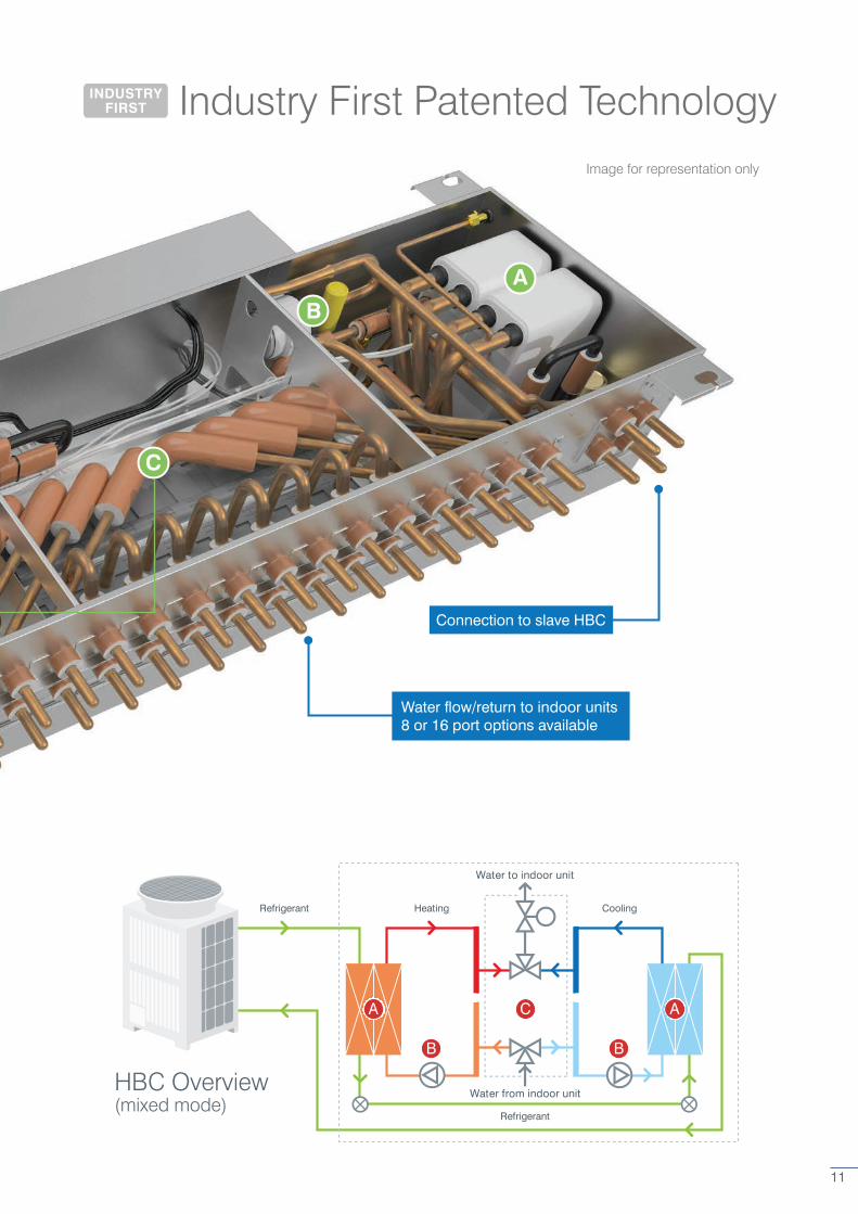
Industry First Patented TechnologyINDUSTRY FIRST
11
Connection to slave HBC
Water flow/return to indoor units 8 or 16 port options available
Image for representation only
Water to indoor unit
HeatingRefrigerant Cooling
Water from indoor unit
Refrigerant
A AC
B B
HBC Overview(mixed mode)
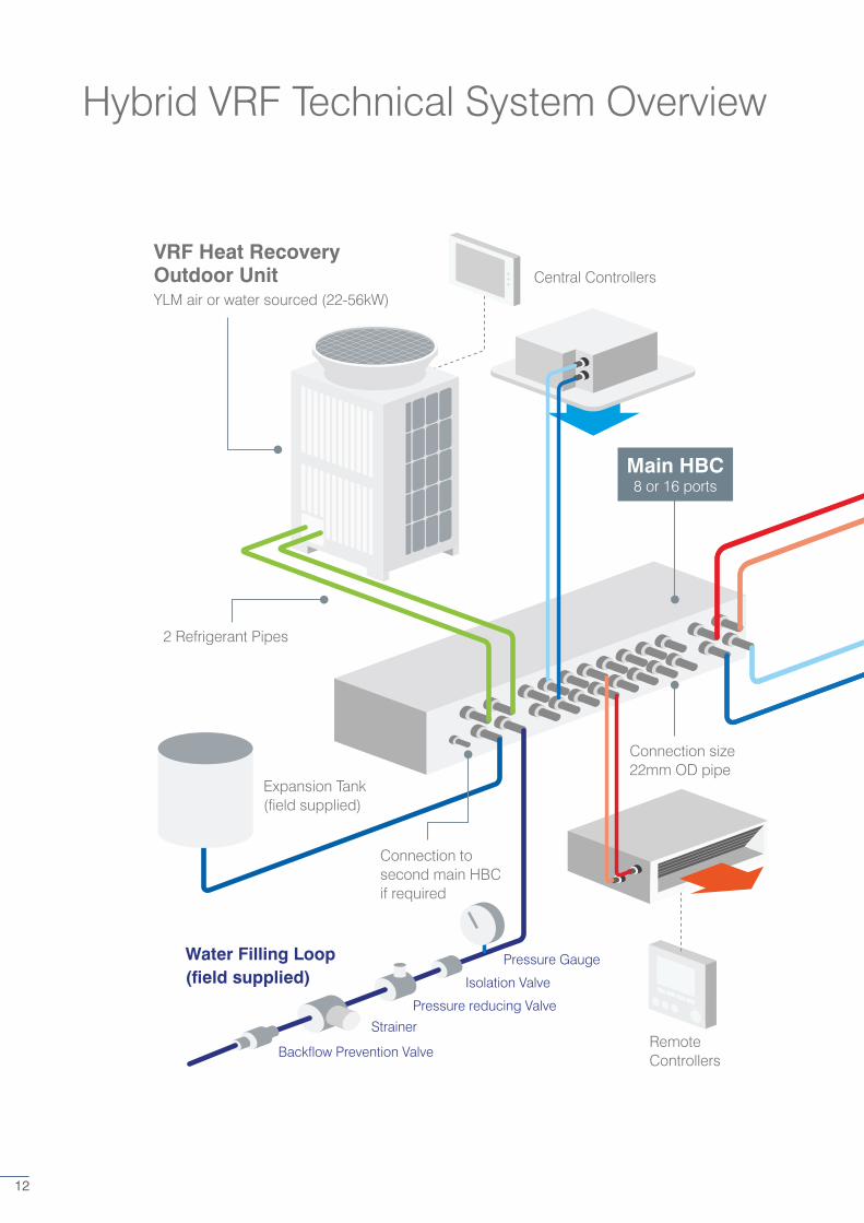
Hybrid VRF Technical System Overview
VRF Heat Recovery Outdoor UnitYLM air or water sourced (22-56kW)
Main HBC8 or 16 ports
Water Filling Loop (field supplied)
Central Controllers
2 Refrigerant Pipes
Expansion Tank (field supplied)
Connection size 22mm OD pipe
Connection to second main HBC if required
Remote Controllers
Pressure Gauge
Isolation Valve
Pressure reducing Valve
Strainer
Backflow Prevention Valve
12
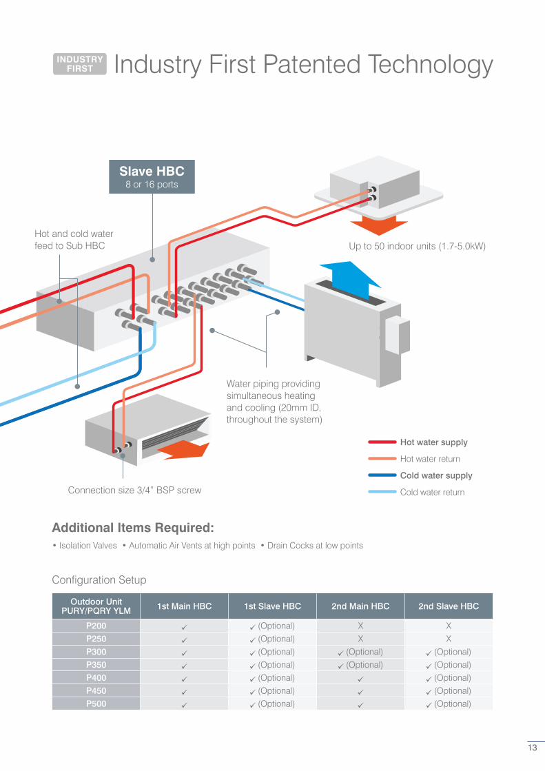
Industry First Patented Technology
Slave HBC8 or 16 ports
Hot and cold water feed to Sub HBC Up to 50 indoor units (1.7-5.0kW)
Water piping providing simultaneous heating and cooling (20mm ID, throughout the system)
Connection size 3/4” BSP screw
Hot water supply
Hot water return
Cold water supply
Cold water return
Additional Items Required:• Isolation Valves • Automatic Air Vents at high points • Drain Cocks at low points
Configuration Setup
Outdoor Unit PURY/PQRY YLM 1st Main HBC 1st Slave HBC 2nd Main HBC 2nd Slave HBC
P200 (Optional) X XP250 (Optional) X XP300 (Optional) (Optional) (Optional)P350 (Optional) (Optional) (Optional)P400 (Optional) (Optional)P450 (Optional) (Optional)P500 (Optional) (Optional)
INDUSTRY FIRST
13
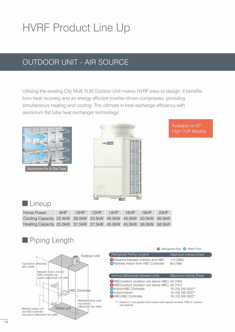
Lineup
Piping Length
Horse Power 8HP 10HPCooling CapacityHeating Capacity
22.4kW 28.0kW12HP
33.5kW14HP
40.0kW16HP
45.0kW18HP
50.0kW20HP
56.0kW25.0kW 31.5kW 37.5kW 45.0kW 45.0kW 56.0kW 58.0kW
Refrigerant Piping Lengths
Vertical differentials between units
Distance between outdoor and HBC 110 [360] Farthest indoor from HBC Controller 60 [196]
Outdoor Unit
Between indoor units top-bottom differential 15m [49ft]
Between indoor unit and HBC controller top-bottom differential 15m [49ft]
Between indoor unit and HBC Controller top-bottom differential 15m [49ft]
Top-bottom differential
Indoor unit
HBC controllerHBC Controller
Top-bottom differential50m [164ft]
Between indoor unit and HBC controller top-bottom differential 15m [49ft]
Between indoor units top-bottom differential 15m [49ft]
HEAT SOURCE UNITThe CITY MULTI WR2 series provides all of the advantages of
the R2 series with the added advantages of a water heat
source system, making it suitable for wider range of
applications in high rises, frigid climates, coastal areas, etc.
Lineup
Piping length
Horse Power 8HP 10HPCapacity 22.4kW 28.0kW
12HP33.5kW
14HP40.0kW
16HP45.0kW
18HP50.0kW
20HP56.0kW
Refrigerant Piping Lengths Maximum meters [Feet]
Vertical differentials between units Maximum meters [Feet]
Distance between heat source and HBC Farthest indoor from HBC controller
Heat source unit
Between indoor units top-bottom differential 15m [49ft]
Between indoor unit and HBC controller top-bottom differential 15m [49ft]
Between indoor unit and HBC controller top-bottom differential 15m [49ft]
Top-bottom differential
Indoor unit
HBC controllerHBC controller
Top-bottom differential50m [164ft]
Between indoor unit and HBC controller top-bottom differential 15m [49ft]
Between indoor units top-bottom differential 15m [49ft]
HBC/outdoor (outdoor unit above HBC) 50 [164]HBC/outdoor (outdoor unit below HBC) 40 [131]Indoor/HBC Controller 15 (10) [49 (32)]*1 Indoor/indoor 15 (10) [49 (32)]*1 HBC/HBC Controller 15 (10) [49 (32)]*1
*1. Values in ( ) are applied when indoor total capacity exceeds 130% of outdoor unit capacity.
HBC/heat source (heat source unit above HBC)HBC/heat source (heat source unit below HBC)Indoor/HBC controllerIndoor/indoorHBC/HBC controller
*1. Values in ( ) are applied when indoor total capacity exceeds 130% of outdoor unit capacity.
110 [360] 60 [196]
50 [164]40 [131]15 (10) [49 (32)]*1 15 (10) [49 (32)]*1 15 (10) [49 (32)]*1
NEW
R
RR
R
W
: Refrigerant Pipe : Water PipeR W : Refrigerant Pipe : Water PipeR W
WW
R
RR
R
W
WW
Maximum metres [Feet]
Maximum metres [Feet]
HVRF Product Line Up
OUTDOOR UNIT - AIR SOURCE
Utilising the existing City Multi YLM Outdoor Unit makes HVRF easy to design. It benefits
from heat recovery and an energy efficient inverter-driven compressor, providing
simultaneous heating and cooling. The ultimate in heat exchange efficiency with
aluminium flat tube heat exchanger technology!
Aluminium Fin & Flat Tube
Available on EP High COP Models
14
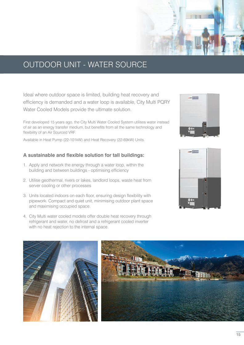
OUTDOOR UNIT - WATER SOURCE
15
Ideal where outdoor space is limited, building heat recovery and
efficiency is demanded and a water loop is available, City Multi PQRY
Water Cooled Models provide the ultimate solution.
First developed 15 years ago, the City Multi Water Cooled System utilises water instead of air as an energy transfer medium, but benefits from all the same technology and flexibility of an Air Sourced VRF.
Available in Heat Pump (22-101kW) and Heat Recovery (22-69kW) Units.
A sustainable and flexible solution for tall buildings:
1. Apply and network the energy through a water loop, within the building and between buildings - optimising efficiency
2. Utilise geothermal, rivers or lakes, landlord loops, waste heat from server cooling or other processes
3. Units located indoors on each floor, ensuring design flexibility with pipework. Compact and quiet unit, minimising outdoor plant space and maximising occupied space.
4. City Multi water cooled models offer double heat recovery through refrigerant and water, no defrost and a refrigerant cooled inverter with no heat rejection to the internal space.
With the connection of three Expansion Controllers (AE-50E/EW-50E), a
maximum of 200 units/groups can be connected to an AE-200E.
This system also allows the use of other controllers such as PAC-YT52CRA or AT-50B.
[Advanced functions]
• Error information
• Operation lock
• Language selection
[Advanced functions]
• 10.4 inch LCD touch screen display
• Web access – central control
available via web browser
Remote Controller
Centralised Controller
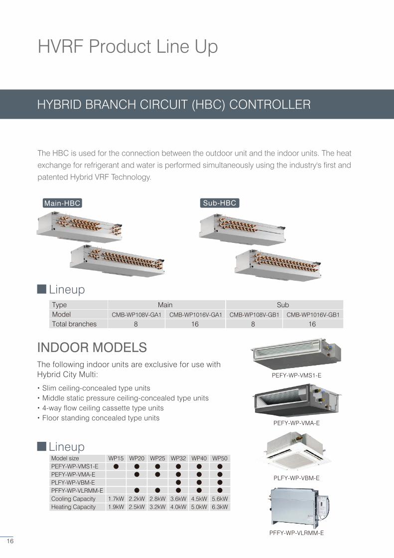
Lineup
CMB-WP108V-GA1 CMB-WP1016V-GA1Model8
CMB-WP1016V-GB1
MainType
16 8 16Total branches
PAR-32MAA
AE-200E
PAC-YT52CRA
PEFY-WP-VMS1-E
PFFY-WP-VLRMM-E
PEFY-WP-VMA-E
PLFY-WP-VBM-E
AT-50B
INDOOR MODELSThe following indoor units are exclusive for use with Hybrid City Multi:
LineupModel sizePEFY-WP-VMS1-EPEFY-WP-VMA-EPLFY-WP-VBM-EPFFY-WP-VLRMM-ECooling CapacityHeating Capacity
WP15
1.7kW1.9kW
WP20
2.2kW2.5kW
WP25
2.8kW3.2kW
WP32
3.6kW4.0kW
WP40
4.5kW5.0kW
WP50
5.6kW6.3kW
Sub-HBCMain-HBC
CMB-WP108V-GB1
Sub•365-day time scheduler
•Energy consumption monitoring
•Programmable floor plan
• Timer
• Temperature range setting
・Slim ceiling-concealed type units・Middle static pressure ceiling-concealed type units・4-way flow ceiling cassette type units・Floor standing concealed type units
HVRF Product Line Up
HYBRID BRANCH CIRCUIT (HBC) CONTROLLER
The HBC is used for the connection between the outdoor unit and the indoor units. The heat
exchange for refrigerant and water is performed simultaneously using the industry's first and
patented Hybrid VRF Technology.
16
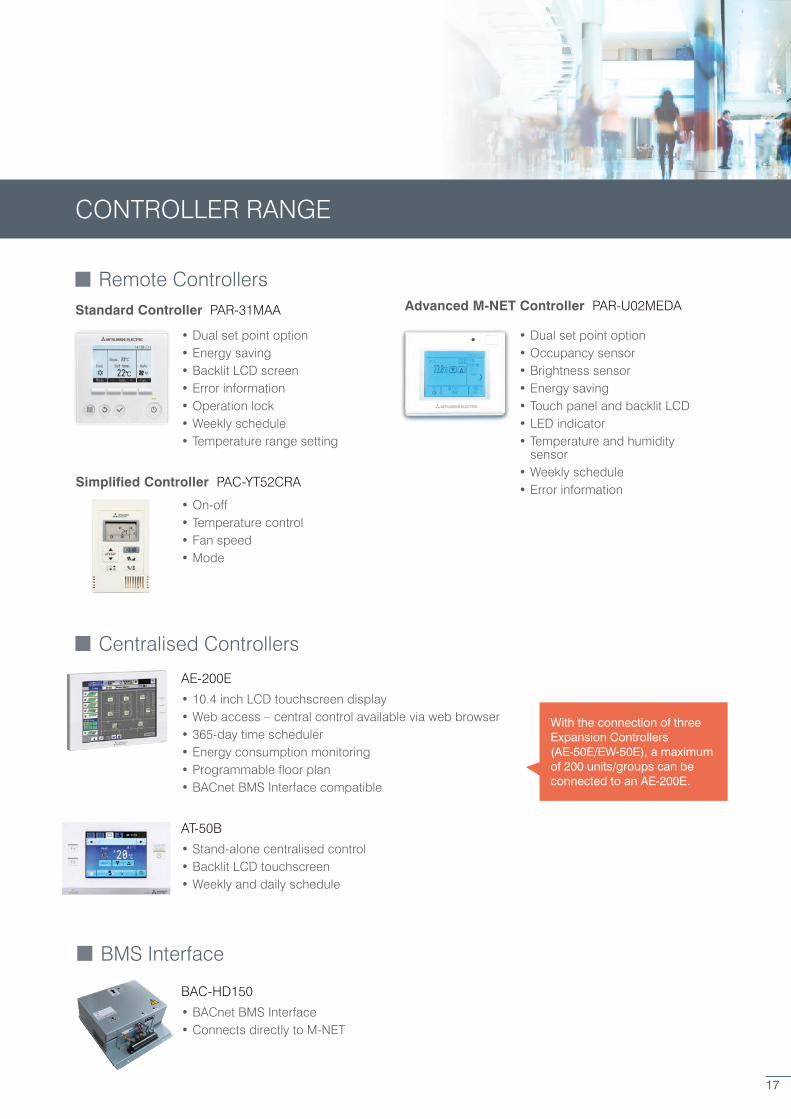
CONTROLLER RANGE
Remote Controllers
Centralised Controllers
• Dual set point option• Energy saving• Backlit LCD screen • Error information • Operation lock • Weekly schedule• Temperature range setting
• On-off• Temperature control• Fan speed• Mode
• Dual set point option• Occupancy sensor• Brightness sensor• Energy saving• Touch panel and backlit LCD• LED indicator• Temperature and humidity
sensor• Weekly schedule• Error information
Standard Controller PAR-31MAA
Simplified Controller PAC-YT52CRA
Advanced M-NET Controller PAR-U02MEDA
• Stand-alone centralised control• Backlit LCD touchscreen• Weekly and daily schedule
AT-50B
• 10.4 inch LCD touchscreen display• Web access – central control available via web browser• 365-day time scheduler • Energy consumption monitoring• Programmable floor plan• BACnet BMS Interface compatible
AE-200E
BMS Interface
• BACnet BMS Interface• Connects directly to M-NET
BAC-HD150
With the connection of three Expansion Controllers (AE-50E/EW-50E), a maximum of 200 units/groups can be connected to an AE-200E.
17
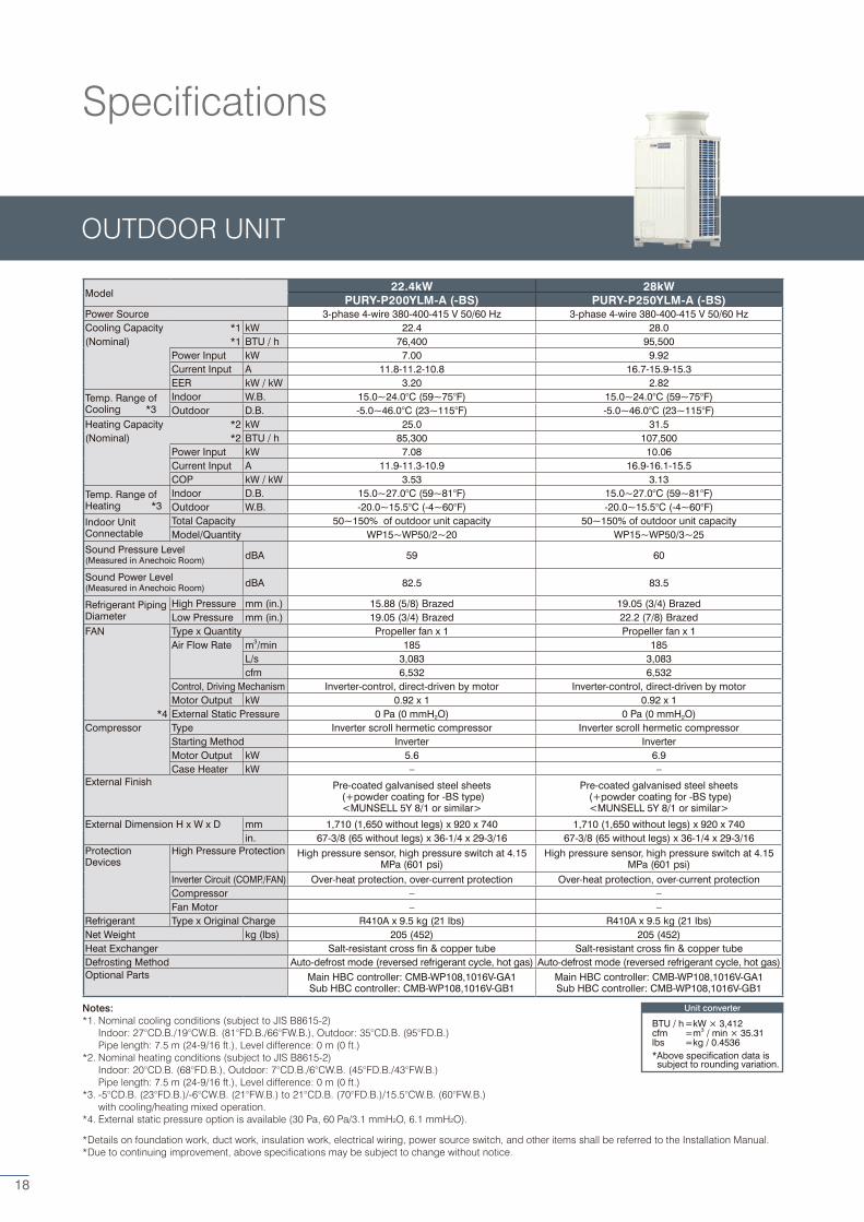
Model 22.4kW 28kW
PURY-P200YLM-A (-BS) PURY-P250YLM-A (-BS)Power Source 3-phase 4-wire 380-400-415 V 50/60 Hz 3-phase 4-wire 380-400-415 V 50/60 HzCooling Capacity *1 kW 22.4 28.0(Nominal) *1 BTU / h 76,400 95,500
Power Input kW 7.00 9.92Current Input A 11.8-11.2-10.8 16.7-15.9-15.3EER kW / kW 3.20 2.82
Temp. Range ofCooling *3
Indoor W.B. 15.0~24.0°C (59~75°F) 15.0~24.0°C (59~75°F)Outdoor D.B. -5.0~46.0°C (23~115°F) -5.0~46.0°C (23~115°F)
Heating Capacity *2 kW 25.0 31.5(Nominal) *2 BTU / h 85,300 107,500
Power Input kW 7.08 10.06Current Input A 11.9-11.3-10.9 16.9-16.1-15.5COP kW / kW 3.53 3.13
Temp. Range ofHeating *3
Indoor D.B. 15.0~27.0°C (59~81°F) 15.0~27.0°C (59~81°F)Outdoor W.B. -20.0~15.5°C (-4~60°F) -20.0~15.5°C (-4~60°F)
Indoor UnitConnectable
Total Capacity 50~150% of outdoor unit capacity 50~150% of outdoor unit capacityModel/Quantity WP15~WP50/2~20 WP15~WP50/3~25
Sound Pressure Level (Measured in Anechoic Room) dBA 59 60
Sound Power Level (Measured in Anechoic Room) dBA 82.5 83.5
Refrigerant PipingDiameter
High Pressure mm (in.) 15.88 (5/8) Brazed 19.05 (3/4) BrazedLow Pressure mm (in.) 19.05 (3/4) Brazed 22.2 (7/8) Brazed
FAN Type x Quantity Propeller fan x 1 Propeller fan x 1Air Flow Rate m3/min 185 185
L/s 3,083 3,083cfm 6,532 6,532
Control, Driving Mechanism Inverter-control, direct-driven by motor Inverter-control, direct-driven by motorMotor Output kW 0.92 x 1 0.92 x 1
*4 External Static Pressure 0 Pa (0 mmH2O) 0 Pa (0 mmH2O)Compressor Type Inverter scroll hermetic compressor Inverter scroll hermetic compressor
Starting Method Inverter InverterMotor Output kW 5.6 6.9Case Heater kW – –
External Finish Pre-coated galvanised steel sheets (+powder coating for -BS type)<MUNSELL 5Y 8/1 or similar>
Pre-coated galvanised steel sheets (+powder coating for -BS type)<MUNSELL 5Y 8/1 or similar>
External Dimension H x W x D mm 1,710 (1,650 without legs) x 920 x 740 1,710 (1,650 without legs) x 920 x 740in. 67-3/8 (65 without legs) x 36-1/4 x 29-3/16 67-3/8 (65 without legs) x 36-1/4 x 29-3/16
ProtectionDevices
High Pressure Protection High pressure sensor, high pressure switch at 4.15 MPa (601 psi)
High pressure sensor, high pressure switch at 4.15 MPa (601 psi)
Inverter Circuit (COMP./FAN) Over-heat protection, over-current protection Over-heat protection, over-current protectionCompressor – –Fan Motor – –
Refrigerant Type x Original Charge R410A x 9.5 kg (21 lbs) R410A x 9.5 kg (21 lbs)Net Weight kg (lbs) 205 (452) 205 (452)Heat Exchanger Salt-resistant cross fin & copper tube Salt-resistant cross fin & copper tubeDefrosting Method Auto-defrost mode (reversed refrigerant cycle, hot gas) Auto-defrost mode (reversed refrigerant cycle, hot gas)Optional Parts Main HBC controller: CMB-WP108,1016V-GA1
Sub HBC controller: CMB-WP108,1016V-GB1Main HBC controller: CMB-WP108,1016V-GA1Sub HBC controller: CMB-WP108,1016V-GB1
Notes:*1. Nominal cooling conditions (subject to JIS B8615-2) Indoor: 27°CD.B./19°CW.B. (81°FD.B./66°FW.B.), Outdoor: 35°CD.B. (95°FD.B.) Pipe length: 7.5 m (24-9/16 ft.), Level difference: 0 m (0 ft.)*2. Nominal heating conditions (subject to JIS B8615-2) Indoor: 20°CD.B. (68°FD.B.), Outdoor: 7°CD.B./6°CW.B. (45°FD.B./43°FW.B.) Pipe length: 7.5 m (24-9/16 ft.), Level difference: 0 m (0 ft.)*3. -5°CD.B. (23°FD.B.)/-6°CW.B. (21°FW.B.) to 21°CD.B. (70°FD.B.)/15.5°CW.B. (60°FW.B.) with cooling/heating mixed operation.*4. External static pressure option is available (30 Pa, 60 Pa/3.1 mmH2O, 6.1 mmH2O).
*Details on foundation work, duct work, insulation work, electrical wiring, power source switch, and other items shall be referred to the Installation Manual. *Due to continuing improvement, above specifications may be subject to change without notice.
Unit converter
BTU / h =kW × 3,412cfm =m3 / min × 35.31lbs =kg / 0.4536*Above specification data is subject to rounding variation.
OUTDOOR UNIT
Specifications
18
Notes:*1. Nominal cooling conditions (subject to JIS B8615-2) Indoor: 27°CD.B./19°CW.B. (81°FD.B./66°FW.B.), Outdoor: 35°CD.B. (95°FD.B.) Pipe length: 7.5 m (24-9/16 ft.), Level difference: 0 m (0 ft.)*2. Nominal heating conditions (subject to JIS B8615-2) Indoor: 20°CD.B. (68°FD.B.), Outdoor: 7°CD.B./6°CW.B. (45°FD.B./43°FW.B.) Pipe length: 7.5 m (24-9/16 ft.), Level difference: 0 m (0 ft.)*3. -5°CD.B. (23°FD.B.)/-6°CW.B. (21°FW.B.) to 21°CD.B. (70°FD.B.)/15.5°CW.B. (60°FW.B.) with cooling/heating mixed operation.*4. External static pressure option is available (30 Pa, 60 Pa/3.1 mmH2O, 6.1 mmH2O).
*Details on foundation work, duct work, insulation work, electrical wiring, power source switch, and other items shall be referred to the Installation Manual. *Due to continuing improvement, above specifications may be subject to change without notice.
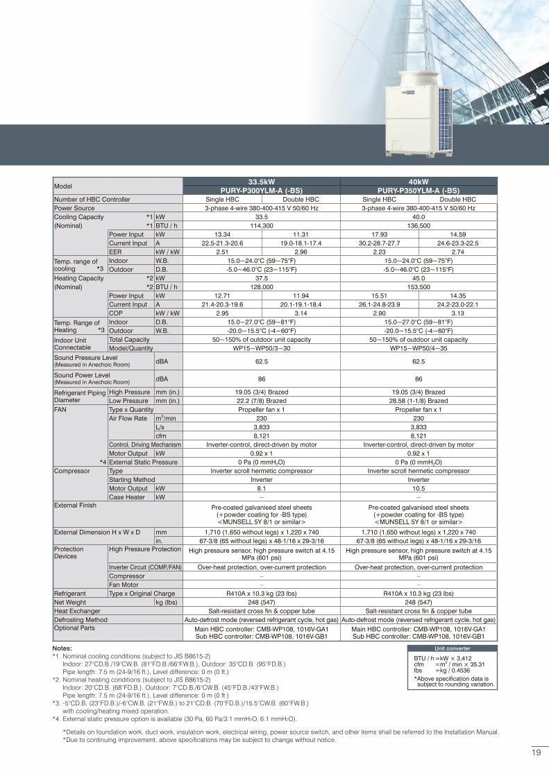
Model 33.5kW 40kW
PURY-P300YLM-A (-BS) PURY-P350YLM-A (-BS)Number of HBC Controller Single HBC Double HBC Single HBC Double HBCPower Source 3-phase 4-wire 380-400-415 V 50/60 Hz 3-phase 4-wire 380-400-415 V 50/60 HzCooling Capacity *1 kW 33.5 40.0(Nominal) *1 BTU / h 114,300 136,500
Power Input kW 13.34 11.31 17.93 14.59Current Input A 22.5-21.3-20.6 19.0-18.1-17.4 30.2-28.7-27.7 24.6-23.3-22.5EER kW / kW 2.51 2.96 2.23 2.74
Temp. range ofcooling *3
Indoor W.B. 15.0~24.0°C (59~75°F) 15.0~24.0°C (59~75°F)Outdoor D.B. -5.0~46.0°C (23~115°F) -5.0~46.0°C (23~115°F)
Heating Capacity *2 kW 37.5 45.0(Nominal) *2 BTU / h 128,000 153,500
Power Input kW 12.71 11.94 15.51 14.35Current Input A 21.4-20.3-19.6 20.1-19.1-18.4 26.1-24.8-23.9 24.2-23.0-22.1COP kW / kW 2.95 3.14 2.90 3.13
Temp. Range ofHeating *3
Indoor D.B. 15.0~27.0°C (59~81°F) 15.0~27.0°C (59~81°F)Outdoor W.B. -20.0~15.5°C (-4~60°F) -20.0~15.5°C (-4~60°F)
Indoor UnitConnectable
Total Capacity 50~150% of outdoor unit capacity 50~150% of outdoor unit capacityModel/Quantity WP15~WP50/3~30 WP15~WP50/4~35
Sound Pressure Level (Measured in Anechoic Room) dBA 62.5 62.5
Sound Power Level (Measured in Anechoic Room) dBA 86 86
Refrigerant PipingDiameter
High Pressure mm (in.) 19.05 (3/4) Brazed 19.05 (3/4) BrazedLow Pressure mm (in.) 22.2 (7/8) Brazed 28.58 (1-1/8) Brazed
FAN Type x Quantity Propeller fan x 1 Propeller fan x 1Air Flow Rate m3/min 230 230
L/s 3,833 3,833cfm 8,121 8,121
Control, Driving Mechanism Inverter-control, direct-driven by motor Inverter-control, direct-driven by motorMotor Output kW 0.92 x 1 0.92 x 1
*4 External Static Pressure 0 Pa (0 mmH2O) 0 Pa (0 mmH2O)Compressor Type Inverter scroll hermetic compressor Inverter scroll hermetic compressor
Starting Method Inverter InverterMotor Output kW 8.1 10.5Case Heater kW – –
External Finish Pre-coated galvanised steel sheets (+powder coating for -BS type)<MUNSELL 5Y 8/1 or similar>
Pre-coated galvanised steel sheets (+powder coating for -BS type)<MUNSELL 5Y 8/1 or similar>
External Dimension H x W x D mm 1,710 (1,650 without legs) x 1,220 x 740 1,710 (1,650 without legs) x 1,220 x 740in. 67-3/8 (65 without legs) x 48-1/16 x 29-3/16 67-3/8 (65 without legs) x 48-1/16 x 29-3/16
ProtectionDevices
High Pressure Protection High pressure sensor, high pressure switch at 4.15 MPa (601 psi)
High pressure sensor, high pressure switch at 4.15 MPa (601 psi)
Inverter Circuit (COMP./FAN) Over-heat protection, over-current protection Over-heat protection, over-current protectionCompressor – –Fan Motor – –
Refrigerant Type x Original Charge R410A x 10.3 kg (23 lbs) R410A x 10.3 kg (23 lbs)Net Weight kg (lbs) 248 (547) 248 (547)Heat Exchanger Salt-resistant cross fin & copper tube Salt-resistant cross fin & copper tubeDefrosting Method Auto-defrost mode (reversed refrigerant cycle, hot gas) Auto-defrost mode (reversed refrigerant cycle, hot gas)Optional Parts Main HBC controller: CMB-WP108, 1016V-GA1
Sub HBC controller: CMB-WP108, 1016V-GB1Main HBC controller: CMB-WP108, 1016V-GA1Sub HBC controller: CMB-WP108, 1016V-GB1
Unit converter
BTU / h =kW × 3,412cfm =m3 / min × 35.31lbs =kg / 0.4536*Above specification data is subject to rounding variation.
19
Notes:*1. Nominal cooling conditions (subject to JIS B8615-2) Indoor: 27°CD.B./19°CW.B. (81°FD.B./66°FW.B.), Outdoor: 35°CD.B. (95°FD.B.) Pipe length: 7.5 m (24-9/16 ft.), Level difference: 0 m (0 ft.)*2. Nominal heating conditions (subject to JIS B8615-2) Indoor: 20°CD.B. (68°FD.B.), Outdoor: 7°CD.B./6°CW.B. (45°FD.B./43°FW.B.) Pipe length: 7.5 m (24-9/16 ft.), Level difference: 0 m (0 ft.)*3. -5°CD.B. (23°FD.B.)/-6°CW.B. (21°FW.B.) to 21°CD.B. (70°FD.B.)/15.5°CW.B. (60°FW.B.) with cooling/heating mixed operation.*4. External static pressure option is available (30 Pa, 60 Pa/3.1 mmH2O, 6.1 mmH2O).
*Details on foundation work, duct work, insulation work, electrical wiring, power source switch, and other items shall be referred to the Installation Manual. *Due to continuing improvement, above specifications may be subject to change without notice.
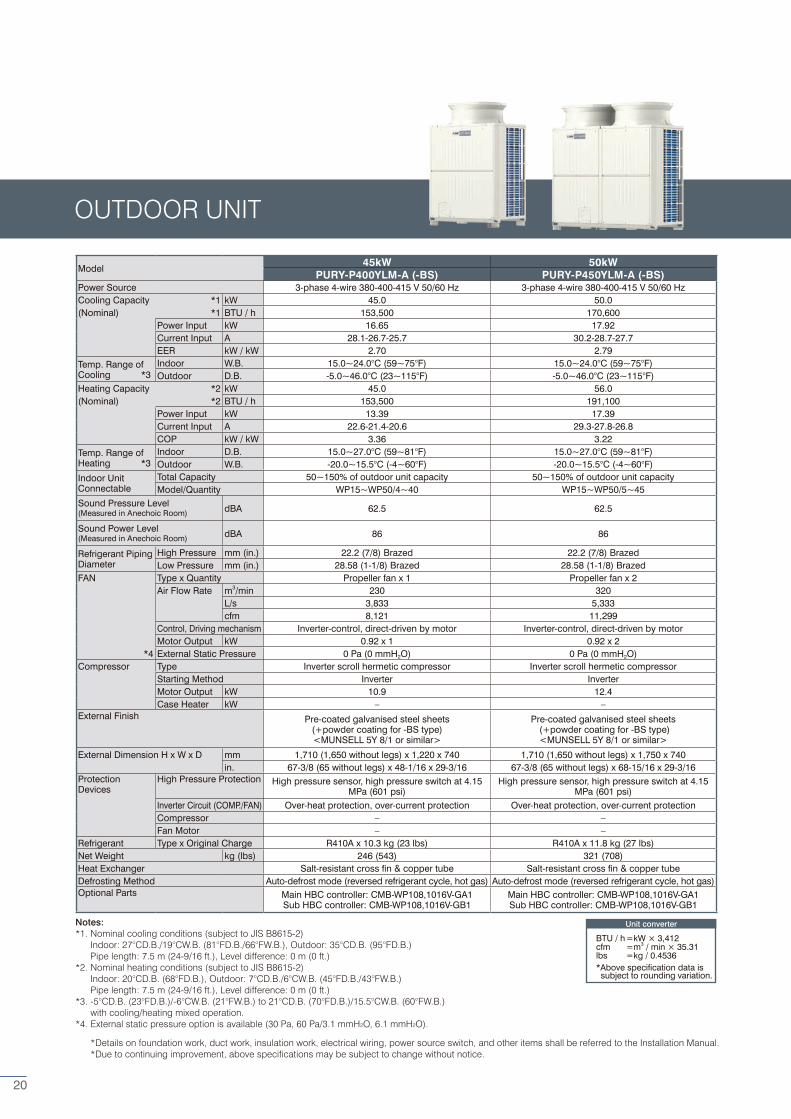
Model 45kW 50kW
PURY-P400YLM-A (-BS) PURY-P450YLM-A (-BS)Power Source 3-phase 4-wire 380-400-415 V 50/60 Hz 3-phase 4-wire 380-400-415 V 50/60 HzCooling Capacity *1 kW 45.0 50.0(Nominal) *1 BTU / h 153,500 170,600
Power Input kW 16.65 17.92Current Input A 28.1-26.7-25.7 30.2-28.7-27.7EER kW / kW 2.70 2.79
Temp. Range ofCooling *3
Indoor W.B. 15.0~24.0°C (59~75°F) 15.0~24.0°C (59~75°F)Outdoor D.B. -5.0~46.0°C (23~115°F) -5.0~46.0°C (23~115°F)
Heating Capacity *2 kW 45.0 56.0(Nominal) *2 BTU / h 153,500 191,100
Power Input kW 13.39 17.39Current Input A 22.6-21.4-20.6 29.3-27.8-26.8COP kW / kW 3.36 3.22
Temp. Range ofHeating *3
Indoor D.B. 15.0~27.0°C (59~81°F) 15.0~27.0°C (59~81°F)Outdoor W.B. -20.0~15.5°C (-4~60°F) -20.0~15.5°C (-4~60°F)
Indoor UnitConnectable
Total Capacity 50~150% of outdoor unit capacity 50~150% of outdoor unit capacityModel/Quantity WP15~WP50/4~40 WP15~WP50/5~45
Sound Pressure Level (Measured in Anechoic Room) dBA 62.5 62.5
Sound Power Level (Measured in Anechoic Room) dBA 86 86
Refrigerant PipingDiameter
High Pressure mm (in.) 22.2 (7/8) Brazed 22.2 (7/8) BrazedLow Pressure mm (in.) 28.58 (1-1/8) Brazed 28.58 (1-1/8) Brazed
FAN Type x Quantity Propeller fan x 1 Propeller fan x 2Air Flow Rate m3/min 230 320
L/s 3,833 5,333cfm 8,121 11,299
Control, Driving mechanism Inverter-control, direct-driven by motor Inverter-control, direct-driven by motorMotor Output kW 0.92 x 1 0.92 x 2
*4 External Static Pressure 0 Pa (0 mmH2O) 0 Pa (0 mmH2O)Compressor Type Inverter scroll hermetic compressor Inverter scroll hermetic compressor
Starting Method Inverter InverterMotor Output kW 10.9 12.4Case Heater kW – –
External Finish Pre-coated galvanised steel sheets (+powder coating for -BS type)<MUNSELL 5Y 8/1 or similar>
Pre-coated galvanised steel sheets (+powder coating for -BS type)<MUNSELL 5Y 8/1 or similar>
External Dimension H x W x D mm 1,710 (1,650 without legs) x 1,220 x 740 1,710 (1,650 without legs) x 1,750 x 740in. 67-3/8 (65 without legs) x 48-1/16 x 29-3/16 67-3/8 (65 without legs) x 68-15/16 x 29-3/16
ProtectionDevices
High Pressure Protection High pressure sensor, high pressure switch at 4.15 MPa (601 psi)
High pressure sensor, high pressure switch at 4.15 MPa (601 psi)
Inverter Circuit (COMP./FAN) Over-heat protection, over-current protection Over-heat protection, over-current protectionCompressor – –Fan Motor – –
Refrigerant Type x Original Charge R410A x 10.3 kg (23 lbs) R410A x 11.8 kg (27 lbs)Net Weight kg (lbs) 246 (543) 321 (708)Heat Exchanger Salt-resistant cross fin & copper tube Salt-resistant cross fin & copper tubeDefrosting Method Auto-defrost mode (reversed refrigerant cycle, hot gas) Auto-defrost mode (reversed refrigerant cycle, hot gas)Optional Parts Main HBC controller: CMB-WP108,1016V-GA1
Sub HBC controller: CMB-WP108,1016V-GB1Main HBC controller: CMB-WP108,1016V-GA1Sub HBC controller: CMB-WP108,1016V-GB1
Unit converter
BTU / h =kW × 3,412cfm =m3 / min × 35.31lbs =kg / 0.4536*Above specification data is subject to rounding variation.
OUTDOOR UNIT
20
Notes:*1. Nominal cooling conditions (subject to JIS B8615-2) Indoor: 27°CD.B./19°CW.B. (81°FD.B./66°FW.B.), Outdoor: 35°CD.B. (95°FD.B.) Pipe length: 7.5 m (24-9/16 ft.), Level difference: 0 m (0 ft.)*2. Nominal heating conditions (subject to JIS B8615-2) Indoor: 20°CD.B. (68°FD.B.), Outdoor: 7°CD.B./6°CW.B. (45°FD.B./43°FW.B.) Pipe length: 7.5 m (24-9/16 ft.), Level difference: 0 m (0 ft.)*3. -5°CD.B. (23°FD.B.)/-6°CW.B. (21°FW.B.) to 21°CD.B. (70°FD.B.)/15.5°CW.B. (60°FW.B.) with cooling/heating mixed operation.*4. External static pressure option is available (30 Pa, 60 Pa/3.1 mmH2O, 6.1 mmH2O).
*Details on foundation work, duct work, insulation work, electrical wiring, power source switch, and other items shall be referred to the Installation Manual. *Due to continuing improvement, above specifications may be subject to change without notice.
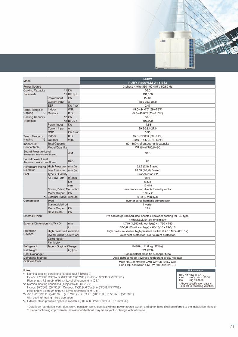
Model 56kW
PURY-P500YLM-A1 (-BS)Power Source 3-phase 4-wire 380-400-415 V 50/60 HzCooling Capacity *1 kW 56.0(Nominal) *1 BTU / h 191,100
Power Input kW 22.67Current Input A 38.2-36.3-35.0EER kW / kW 2.47
Temp. Range ofCooling *3
Indoor W.B. 15.0~24.0°C (59~75°F)Outdoor D.B. -5.0~46.0°C (23~115°F)
Heating Capacity *2 kW 58.0(Nominal) *2 BTU / h 197,900
Power Input kW 17.53Current Input A 29.5-28.1-27.0COP kW / kW 3.30
Temp. Range ofHeating *3
Indoor D.B. 15.0~27.0°C (59~81°F)Outdoor W.B. -20.0~15.5°C (-4~60°F)
Indoor UnitConnectable
Total Capacity 50~150% of outdoor unit capacityModel/Quantity WP15~WP50/5~50
Sound Pressure Level (Measured in Anechoic Room) dBA 63.5
Sound Power Level (Measured in Anechoic Room) dBA 87
Refrigerant PipingDiameter
High Pressure mm (in.) 22.2 (7/8) BrazedLow Pressure mm (in.) 28.58 (1-1/8) Brazed
FAN Type x Quantity Propeller fan x 2Air Flow Rate m3/min 380
L/s 6,333cfm 13,418
Control, Driving Mechanism Inverter-control, direct-driven by motorMotor Output kW 0.92 x 2
*4 External Static Pressure 0 Pa (0 mmH2O)Compressor Type Inverter scroll hermetic compressor
Starting Method InverterMotor Output kW 13.4Case Heater kW –
External Finish Pre-coated galvanised steel sheets (+powder coating for -BS type)<MUNSELL 5Y 8/1 or similar>
External Dimension H x W x D mm 1,710 (1,650 without legs) x 1,750 x 740in. 67-3/8 (65 without legs) x 68-15/16 x 29-3/16
ProtectionDevices
High Pressure Protection High pressure sensor, high pressure switch at 4.15 MPa (601 psi)Inverter Circuit (COMP./FAN) Over-heat protection, over-current protectionCompressor –Fan Motor –
Refrigerant Type x Original Charge R410A x 11.8 kg (27 lbs)Net Weight kg (lbs) 321 (708)Heat Exchanger Salt-resistant cross fin & copper tubeDefrosting Method Auto-defrost mode (reversed refrigerant cycle, hot gas)Optional Parts Main HBC controller: CMB-WP108,1016V-GA1
Sub HBC controller: CMB-WP108,1016V-GB1
Unit converter
BTU / h =kW × 3,412cfm =m3 / min × 35.31lbs =kg / 0.4536*Above specification data is subject to rounding variation.
21

Model 22.4kW 28kW
PURY-EP200YLM-A1 (-BS) PURY-EP250YLM-A1 (-BS)Power Source 3-phase 4-wire 380-400-415 V 50/60 Hz 3-phase 4-wire 380-400-415 V 50/60 HzCooling Capacity *1 kW 22.4 28.0(Nominal) *1 BTU / h 76,400 95,500
Power Input kW 6.27 8.77Current Input A 10.5-10.0-9.6 14.8-14.0-13.5EER kW / kW 3.57 3.19
Temp. Range ofCooling *3
Indoor W.B. 15.0~24.0°C (59~75°F) 15.0~24.0°C (59~75°F)Outdoor D.B. -5.0~46.0°C (23~115°F) -5.0~46.0°C (23~115°F)
Heating Capacity *2 kW 25.0 31.5(Nominal) *2 BTU / h 85,300 107,500
Power Input kW 6.92 9.84Current Input A 11.6-11.0-10.6 16.6-15.7-15.2COP kW / kW 3.61 3.20
Temp. Range ofHeating *3
Indoor D.B. 15.0~27.0°C (59~81°F) 15.0~27.0°C (59~81°F)Outdoor W.B. -20.0~15.5°C (-4~60°F) -20.0~15.5°C (-4~60°F)
Indoor UnitConnectable
Total Capacity 50~150% of outdoor unit capacity 50~150% of outdoor unit capacityModel/Quantity WP15~WP50/2~20 WP15~WP50/3~25
Sound Pressure Level (Measured in Anechoic Room) dBA 59 60
Sound Power Level (Measured in Anechoic Room) dBA 82.5 83.5
Refrigerant PipingDiameter
High Pressure mm (in.) 15.88 (5/8) Brazed 19.05 (3/4) BrazedLow Pressure mm (in.) 19.05 (3/4) Brazed 22.2 (7/8) Brazed
FAN Type x Quantity Propeller fan x 1 Propeller fan x 1Air Flow Rate m3/min 185 185
L/s 3,083 3,083cfm 6,532 6,532
Control, Driving Mechanism Inverter-control, direct-driven by motor Inverter-control, direct-driven by motorMotor Output kW 0.92 x 1 0.92 x 1
*4 External Static Pressure 0 Pa (0 mmH2O) 0 Pa (0 mmH2O)Compressor Type Inverter scroll hermetic compressor Inverter scroll hermetic compressor
Starting Method Inverter InverterMotor Output kW 5.6 6.9Case Heater kW – –
External Finish Pre-coated galvanised steel sheets (+powder coating for -BS type)<MUNSELL 5Y 8/1 or similar>
Pre-coated galvanised steel sheets (+powder coating for -BS type)<MUNSELL 5Y 8/1 or similar>
External Dimension H x W x D mm 1,710 (1,650 without legs) x 920 x 740 1,710 (1,650 without legs) x 920 x 740in. 67-3/8 (65 without legs) x 36-1/4 x 29-3/16 67-3/8 (65 without legs) x 36-1/4 x 29-3/16
ProtectionDevices
High Pressure Protection High pressure sensor, high pressure switch at 4.15 MPa (601 psi)
High pressure sensor, high pressure switch at 4.15 MPa (601 psi)
Inverter Circuit (COMP./FAN) Over-heat protection, over-current protection Over-heat protection, over-current protectionCompressor – –Fan Motor – –
Refrigerant Type x Original Charge R410A x 6.0 kg (14 lbs) R410A x 6.0 kg (14 lbs)Net Weight kg (lbs) 202 (446) 202 (446)Heat Exchanger Salt-resistant cross fin & aluminium tube Salt-resistant cross fin & aluminium tubeDefrosting Method Auto-defrost mode (reversed refrigerant cycle, hot gas) Auto-defrost mode (reversed refrigerant cycle, hot gas)Optional Parts Main HBC controller: CMB-WP108,1016V-GA1
Sub HBC controller: CMB-WP108,1016V-GB1Main HBC controller: CMB-WP108,1016V-GA1Sub HBC controller: CMB-WP108,1016V-GB1
Notes:*1. Nominal cooling conditions (subject to JIS B8615-2) Indoor: 27°CD.B./19°CW.B. (81°FD.B./66°FW.B.), Outdoor: 35°CD.B./24°CW.B. (95°FD.B./75°FW.B.) Pipe length: 7.5 m (24-9/16 ft.), Level difference: 0 m (0 ft.)*2. Nominal heating conditions (subject to JIS B8615-2) Indoor: 20°CD.B. (68°FD.B.), Outdoor: 7°CD.B./6°CW.B. (45°FD.B./43°FW.B.) Pipe length: 7.5 m (24-9/16 ft.), Level difference: 0 m (0 ft.)*3. -5°CD.B. (23°FD.B.)/-6°CW.B. (21°FW.B.) to 21°CD.B. (70°FD.B.)/15.5°CW.B. (60°FW.B.)with cooling/heating mixed operation.*4. External static pressure option is available (30 Pa, 60 Pa/3.1 mmH2O, 6.1 mmH2O).
*Details on foundation work, duct work, insulation work, electrical wiring, power source switch, and other items shall be referred to the Installation Manual. *Due to continuing improvement, above specifications may be subject to change without notice.
Unit converter
BTU / h =kW × 3,412cfm =m3 / min × 35.31lbs =kg / 0.4536*Above specification data is subject to rounding variation.
OUTDOOR UNIT
22
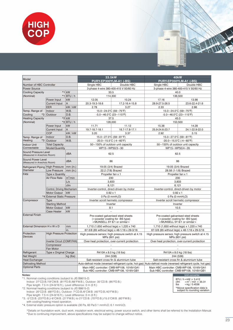
Model 33.5kW 40kW
PURY-EP300YLM-A1 (-BS) PURY-EP350YLM-A1 (-BS)Number of HBC Controller Single HBC Double HBC Single HBC Double HBCPower Source 3-phase 4-wire 380-400-415 V 50/60 Hz 3-phase 4-wire 380-400-415 V 50/60 HzCooling Capacity *1 kW 33.5 40.0(Nominal) *1 BTU / h 114,300 136,500
Power Input kW 12.05 10.24 17.16 13.98Current Input A 20.3-19.3-18.6 17.2-16.4-15.8 28.9-27.5-26.5 23.6-22.4-21.6EER kW / kW 2.78 3.27 2.33 2.86
Temp. Range of Indoor W.B. 15.0~24.0°C (59~75°F) 15.0~24.0°C (59~75°F)Cooling *3 Outdoor D.B. -5.0~46.0°C (23~115°F) -5.0~46.0°C (23~115°F)Heating Capacity *2 kW 37.5 45.0(Nominal) *2 BTU / h 128,000 153,500
Power Input kW 11.71 11.12 15.38 14.28Current Input A 19.7-18.7-18.1 18.7-17.8-17.1 25.9-24.6-23.7 24.1-22.9-22.0COP kW / kW 3.20 3.37 2.92 3.15
Temp. Range ofHeating *3
Indoor D.B. 15.0~27.0°C (59~81°F) 15.0~27.0°C (59~81°F)Outdoor W.B. -20.0~15.5°C (-4~60°F) -20.0~15.5°C (-4~60°F)
Indoor UnitConnectable
Total Capacity 50~150% of outdoor unit capacity 50~150% of outdoor unit capacityModel/Quantity WP15~WP50/3~30 WP15~WP50/4~35
Sound Pressure Level (Measured in Anechoic Room) dBA 62.5 62.5
Sound Power Level (Measured in Anechoic Room) dBA 86 86
Refrigerant PipingDiameter
High Pressure mm (in.) 19.05 (3/4) Brazed 19.05 (3/4) BrazedLow Pressure mm (in.) 22.2 (7/8) Brazed 28.58 (1-1/8) Brazed
FAN Type x Quantity Propeller fan x 1 Propeller fan x 1Air Flow Rate m3/min 230 230
L/s 3,833 3,833cfm 8,121 8,121
Control, Driving Mechanism Inverter-control, direct-driven by motor Inverter-control, direct-driven by motorMotor Output kW 0.92 x 1 0.92 x 1
*4 External Static Pressure 0 Pa (0 mmH2O) 0 Pa (0 mmH2O)Compressor Type Inverter scroll hermetic compressor Inverter scroll hermetic compressor
Starting Method Inverter InverterMotor Output kW 8.1 10.5Case Heater kW – –
External Finish Pre-coated galvanised steel sheets (+powder coating for -BS type)<MUNSELL 5Y 8/1 or similar>
Pre-coated galvanised steel sheets (+powder coating for -BS type)<MUNSELL 5Y 8/1 or similar>
External Dimension H x W x D mm 1,710 (1,650 without legs) x 1,220 x 740 1,710 (1,650 without legs) x 1,220 x 740in. 67-3/8 (65 without legs) x 48-1/16 x 29-3/16 67-3/8 (65 without legs) x 48-1/16 x 29-3/16
ProtectionDevices
High Pressure Protection High pressure sensor, high pressure switch at 4.15 MPa (601 psi)
High pressure sensor, high pressure switch at 4.15 MPa (601 psi)
Inverter Circuit (COMP./FAN) Over-heat protection, over-current protection Over-heat protection, over-current protectionCompressor – –Fan Motor – –
Refrigerant Type x Original Charge R410A x 8.0 kg (18 lbs) R410A x 8.0 kg (18 lbs)Net Weight kg (lbs) 244 (538) 244 (538)Heat Exchanger Salt-resistant cross fin & aluminium tube Salt-resistant cross fin & aluminium tubeDefrosting Method Auto-defrost mode (reversed refrigerant cycle, hot gas) Auto-defrost mode (reversed refrigerant cycle, hot gas)Optional Parts Main HBC controller: CMB-WP108, 1016V-GA1
Sub HBC controller: CMB-WP108, 1016V-GB1Main HBC controller: CMB-WP108, 1016V-GA1Sub HBC controller: CMB-WP108, 1016V-GB1
Notes:*1. Nominal cooling conditions (subject to JIS B8615-2) Indoor: 27°CD.B./19°CW.B. (81°FD.B./66°FW.B.), Outdoor: 35°CD.B. (95°FD.B.) Pipe length: 7.5 m (24-9/16 ft.), Level difference: 0 m (0 ft.)*2. Nominal heating conditions (subject to JIS B8615-2) Indoor: 20°CD.B. (68°FD.B.), Outdoor: 7°CD.B./6°CW.B. (45°FD.B./43°FW.B.) Pipe length: 7.5 m (24-9/16 ft.), Level difference: 0 m (0 ft.)*3. -5°CD.B. (23°FD.B.)/-6°CW.B. (21°FW.B.) to 21°CD.B. (70°FD.B.)/15.5°CW.B. (60°FW.B.) with cooling/heating mixed operation.*4. External static pressure option is available (30 Pa, 60 Pa/3.1 mmH2O, 6.1 mmH2O).
*Details on foundation work, duct work, insulation work, electrical wiring, power source switch, and other items shall be referred to the Installation Manual. *Due to continuing improvement, above specifications may be subject to change without notice.
Unit converter
BTU / h =kW × 3,412cfm =m3 / min × 35.31lbs =kg / 0.4536*Above specification data is subject to rounding variation.
23
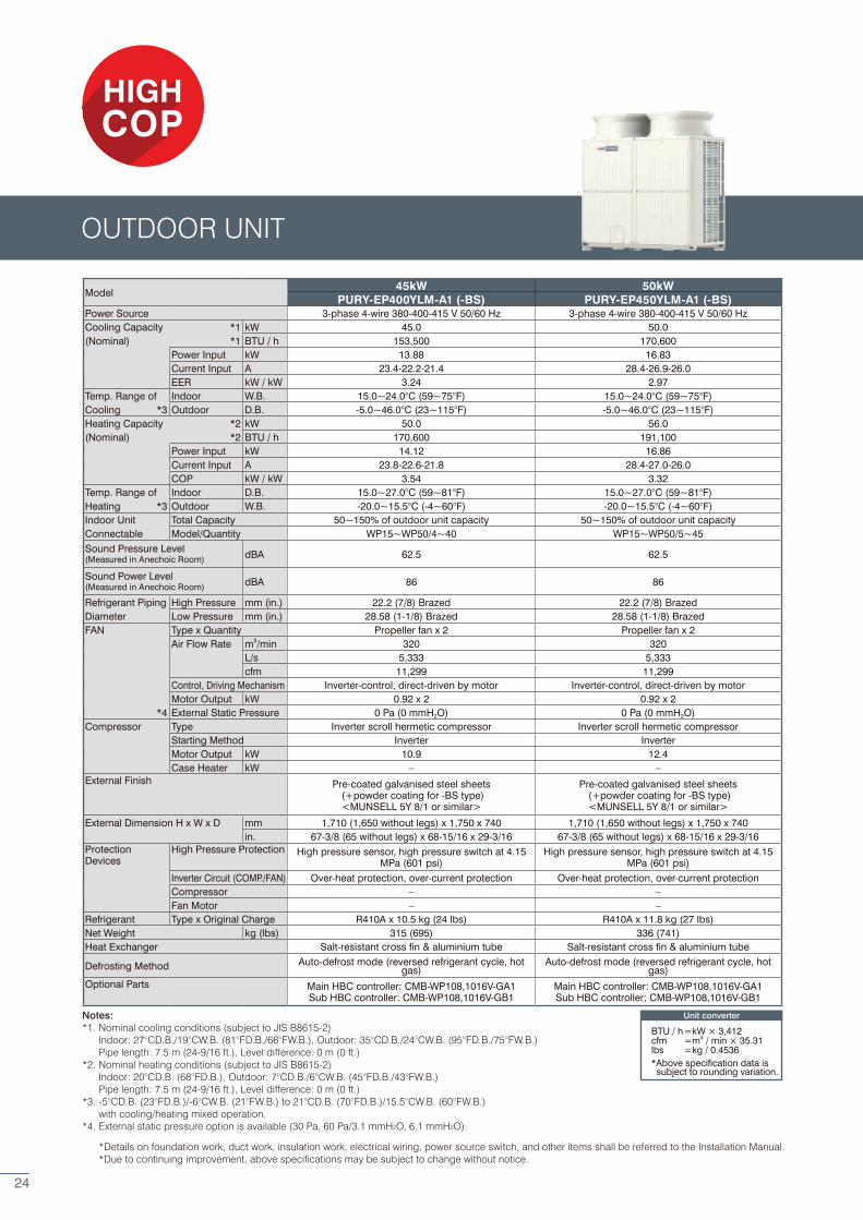
Model 45kW 50kW
PURY-EP400YLM-A1 (-BS) PURY-EP450YLM-A1 (-BS)Power Source 3-phase 4-wire 380-400-415 V 50/60 Hz 3-phase 4-wire 380-400-415 V 50/60 HzCooling Capacity *1 kW 45.0 50.0(Nominal) *1 BTU / h 153,500 170,600
Power Input kW 13.88 16.83Current Input A 23.4-22.2-21.4 28.4-26.9-26.0EER kW / kW 3.24 2.97
Temp. Range of Indoor W.B. 15.0~24.0°C (59~75°F) 15.0~24.0°C (59~75°F)Cooling *3 Outdoor D.B. -5.0~46.0°C (23~115°F) -5.0~46.0°C (23~115°F)Heating Capacity *2 kW 50.0 56.0(Nominal) *2 BTU / h 170,600 191,100
Power Input kW 14.12 16.86Current Input A 23.8-22.6-21.8 28.4-27.0-26.0COP kW / kW 3.54 3.32
Temp. Range of Indoor D.B. 15.0~27.0°C (59~81°F) 15.0~27.0°C (59~81°F)Heating *3 Outdoor W.B. -20.0~15.5°C (-4~60°F) -20.0~15.5°C (-4~60°F)Indoor Unit Total Capacity 50~150% of outdoor unit capacity 50~150% of outdoor unit capacityConnectable Model/Quantity WP15~WP50/4~40 WP15~WP50/5~45Sound Pressure Level (Measured in Anechoic Room) dBA 62.5 62.5
Sound Power Level (Measured in Anechoic Room) dBA 86 86
Refrigerant Piping High Pressure mm (in.) 22.2 (7/8) Brazed 22.2 (7/8) BrazedDiameter Low Pressure mm (in.) 28.58 (1-1/8) Brazed 28.58 (1-1/8) BrazedFAN Type x Quantity Propeller fan x 2 Propeller fan x 2
Air Flow Rate m3/min 320 320L/s 5,333 5,333cfm 11,299 11,299
Control, Driving Mechanism Inverter-control, direct-driven by motor Inverter-control, direct-driven by motorMotor Output kW 0.92 x 2 0.92 x 2
*4 External Static Pressure 0 Pa (0 mmH2O) 0 Pa (0 mmH2O)Compressor Type Inverter scroll hermetic compressor Inverter scroll hermetic compressor
Starting Method Inverter InverterMotor Output kW 10.9 12.4Case Heater kW – –
External Finish Pre-coated galvanised steel sheets (+powder coating for -BS type)<MUNSELL 5Y 8/1 or similar>
Pre-coated galvanised steel sheets (+powder coating for -BS type)<MUNSELL 5Y 8/1 or similar>
External Dimension H x W x D mm 1,710 (1,650 without legs) x 1,750 x 740 1,710 (1,650 without legs) x 1,750 x 740in. 67-3/8 (65 without legs) x 68-15/16 x 29-3/16 67-3/8 (65 without legs) x 68-15/16 x 29-3/16
ProtectionDevices
High Pressure Protection High pressure sensor, high pressure switch at 4.15 MPa (601 psi)
High pressure sensor, high pressure switch at 4.15 MPa (601 psi)
Inverter Circuit (COMP./FAN) Over-heat protection, over-current protection Over-heat protection, over-current protectionCompressor – –Fan Motor – –
Refrigerant Type x Original Charge R410A x 10.5 kg (24 lbs) R410A x 11.8 kg (27 lbs)Net Weight kg (lbs) 315 (695) 336 (741)Heat Exchanger Salt-resistant cross fin & aluminium tube Salt-resistant cross fin & aluminium tube
Defrosting Method Auto-defrost mode (reversed refrigerant cycle, hot gas)
Auto-defrost mode (reversed refrigerant cycle, hot gas)
Optional Parts Main HBC controller: CMB-WP108,1016V-GA1Sub HBC controller: CMB-WP108,1016V-GB1
Main HBC controller: CMB-WP108,1016V-GA1Sub HBC controller: CMB-WP108,1016V-GB1
Notes:*1. Nominal cooling conditions (subject to JIS B8615-2) Indoor: 27°CD.B./19°CW.B. (81°FD.B./66°FW.B.), Outdoor: 35°CD.B./24°CW.B. (95°FD.B./75°FW.B.) Pipe length: 7.5 m (24-9/16 ft.), Level difference: 0 m (0 ft.)*2. Nominal heating conditions (subject to JIS B8615-2) Indoor: 20°CD.B. (68°FD.B.), Outdoor: 7°CD.B./6°CW.B. (45°FD.B./43°FW.B.) Pipe length: 7.5 m (24-9/16 ft.), Level difference: 0 m (0 ft.)*3. -5°CD.B. (23°FD.B.)/-6°CW.B. (21°FW.B.) to 21°CD.B. (70°FD.B.)/15.5°CW.B. (60°FW.B.) with cooling/heating mixed operation.*4. External static pressure option is available (30 Pa, 60 Pa/3.1 mmH2O, 6.1 mmH2O).
*Details on foundation work, duct work, insulation work, electrical wiring, power source switch, and other items shall be referred to the Installation Manual. *Due to continuing improvement, above specifications may be subject to change without notice.
Unit converter
BTU / h =kW × 3,412cfm =m3 / min × 35.31lbs =kg / 0.4536*Above specification data is subject to rounding variation.
OUTDOOR UNIT
24
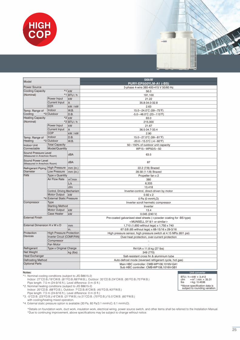
Model 56kW
PURY-EP500YLM-A1 (-BS)Power Source 3-phase 4-wire 380-400-415 V 50/60 HzCooling Capacity *1 kW 56.0(Nominal) *1 BTU / h 191,100
Power Input kW 21.22Current Input A 35.8-34.0-32.8EER kW / kW 2.63
Temp. Range ofCooling *3
Indoor W.B. 15.0~24.0°C (59~75°F)Outdoor D.B. -5.0~46.0°C (23~115°F)
Heating Capacity *2 kW 63.0(Nominal) *2 BTU / h 215,000
Power Input kW 21.67Current Input A 36.5-34.7-33.4COP kW / kW 2.90
Temp. Range ofHeating *3
Indoor D.B. 15.0~27.0°C (59~81°F)Outdoor W.B. -20.0~15.5°C (-4~60°F)
Indoor UnitConnectable
Total Capacity 50~150% of outdoor unit capacityModel/Quantity WP15~WP50/5~50
Sound Pressure Level (Measured in Anechoic Room) dBA 63.5
Sound Power Level (Measured in Anechoic Room) dBA 87
Refrigerant PipingDiameter
High Pressure mm (in.) 22.2 (7/8) BrazedLow Pressure mm (in.) 28.58 (1-1/8) Brazed
FAN Type x Quantity Propeller fan x 2Air Flow Rate m3/min 380
L/s 6,333cfm 13,418
Control, Driving Mechanism Inverter-control, direct-driven by motorMotor Output kW 0.92 x 2
*4 External Static Pressure 0 Pa (0 mmH2O)Compressor Type Inverter scroll hermetic compressor
Starting Method InverterMotor Output kW 13.4Case Heater kW 0.045 (240 V)
External Finish Pre-coated galvanised steel sheets (+powder coating for -BS type)<MUNSELL 5Y 8/1 or similar>
External Dimension H x W x D mm 1,710 (1,650 without legs) x 1,750 x 740in. 67-3/8 (65 without legs) x 68-15/16 x 29-3/16
ProtectionDevices
High Pressure Protection High pressure sensor, high pressure switch at 4.15 MPa (601 psi)Inverter Circuit (COMP./FAN) Over-heat protection, over-current protectionCompressor –Fan Motor –
Refrigerant Type x Original Charge R410A x 11.8 kg (27 lbs)Net Weight kg (lbs) 349 (770)Heat Exchanger Salt-resistant cross fin & aluminium tubeDefrosting Method Auto-defrost mode (reversed refrigerant cycle, hot gas)Optional Parts Main HBC controller: CMB-WP108,1016V-GA1
Sub HBC controller: CMB-WP108,1016V-GB1
Notes:*1. Nominal cooling conditions (subject to JIS B8615-2) Indoor: 27°CD.B./19°CW.B. (81°FD.B./66°FW.B.), Outdoor: 35°CD.B./24°CW.B. (95°FD.B./75°FW.B.) Pipe length: 7.5 m (24-9/16 ft.), Level difference: 0 m (0 ft.)*2. Nominal heating conditions (subject to JIS B8615-2) Indoor: 20°CD.B. (68°FD.B.), Outdoor: 7°CD.B./6°CW.B. (45°FD.B./43°FW.B.) Pipe length: 7.5 m (24-9/16 ft.), Level difference: 0 m (0 ft.)*3. -5°CD.B. (23°FD.B.)/-6°CW.B. (21°FW.B.) to 21°CD.B. (70°FD.B.)/15.5°CW.B. (60°FW.B.) with cooling/heating mixed operation.*4. External static pressure option is available (30 Pa, 60 Pa/3.1 mmH2O, 6.1 mmH2O).
*Details on foundation work, duct work, insulation work, electrical wiring, power source switch, and other items shall be referred to the Installation Manual. *Due to continuing improvement, above specifications may be subject to change without notice.
Unit converter
BTU / h =kW × 3,412cfm =m3 / min × 35.31lbs =kg / 0.4536*Above specification data is subject to rounding variation.
25
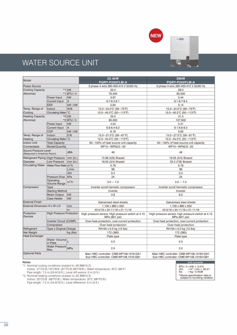
Model 22.4kW 28kW
PQRY-P200YLM-A PQRY-P250YLM-APower Source 3-phase 4-wire 380-400-415 V 50/60 Hz 3-phase 4-wire 380-400-415 V 50/60 HzCooling Capacity *1 kW 22.4 28.0(Nominal) *1 BTU / h 76,400 95,500
Power Input kW 3.97 5.44Current Input A 6.7-6.3-6.1 9.1-8.7-8.4EER kW / kW 5.64 5.14
Temp. Range of Indoor W.B. 15.0~24.0°C (59~75°F) 15.0~24.0°C (59~75°F)Cooling Circulating Water °C 10.0~45.0°C (50~113°F) 10.0~45.0°C (50~113°F)Heating Capacity *2 kW 25.0 31.5(Nominal) *2 BTU / h 85,300 107,500
Power Input kW 4.04 5.41Current Input A 6.8-6.4-6.2 9.1-8.6-8.3COP kW / kW 6.18 5.82
Temp. Range of Indoor D.B. 15.0~27.0°C (59~81°F) 15.0~27.0°C (59~81°F)Heating Circulating Water °C 10.0~45.0°C (50~113°F) 10.0~45.0°C (50~113°F)Indoor Unit Total Capacity 50~150% of heat source unit capacity 50~150% of heat source unit capacityConnectable Model/Quantity WP15~WP50/2~20 WP15~WP50/3~25Sound Pressure Level (Measured in Anechoic Room) dBA 46 48
Refrigerant Piping High Pressure mm (in.) 15.88 (5/8) Brazed 19.05 (3/4) BrazedDiameter Low Pressure mm (in.) 19.05 (3/4) Brazed 22.2 (7/8) BrazedCirculating Water Water Flow Rate m3/h 5.76 5.76
L/min 96 96cfm 3.4 3.4
Pressure Drop kPa 24 24Operating Volume Range m3/h 3.0 ~ 7.2 3.0 ~ 7.2
Compressor Type Inverter scroll hermetic compressor Inverter scroll hermetic compressorStarting Method Inverter InverterMotor Output kW 4.8 6.2Case Heater kW – –
External Finish Galvanised steel sheets Galvanised steel sheetsExternal Dimension H x W x D mm 1,100 x 880 x 550 1,100 x 880 x 550
in. 43-5/16 x 34-11/16 x 21-11/16 43-5/16 x 34-11/16 x 21-11/16ProtectionDevices
High Pressure Protection High pressure sensor, High pressure switch at 4.15 MPa (601 psi)
High pressure sensor, high pressure switch at 4.15 MPa (601 psi)
Inverter Circuit (COMP.) Over-heat protection, over-current protection Over-heat protection, over-current protectionCompressor Over-heat protection Over-heat protection
Refrigerant Type x Original Charge R410A x 5.0 kg (12 lbs) R410A x 5.0 kg (12 lbs)Net Weight kg (lbs) 172 (380) 172 (380)Heat Exchanger Plate type Plate type
Water Volume in Plate L 5.0 5.0
Water Pressure Max. MPa 2.0 2.0
Optional Parts Main HBC controller: CMB-WP108,1016-GA1Sub HBC controller: CMB-WP108,1016-GB1
Main HBC controller: CMB-WP108,1016V-GA1Sub HBC controller: CMB-WP108,1016V-GB1
Notes:*1. Nominal cooling conditions (subject to JIS B8615-2) Indoor: 27°CD.B./19°CW.B. (81°FD.B./66°FW.B.), Water temperature: 30°C (86°F) Pipe length: 7.5 m (24-9/16 ft.), Level diff erence: 0 m (0 ft.)*2. Nominal heating conditions (subject to JIS B8615-2) Indoor: 20°CD.B. (68°FD.B.), Water temperature: 20°C (68°FD.B.) Pipe length: 7.5 m (24-9/16 ft.), Level difference: 0 m (0 ft.)
Unit converter
BTU / h =kW × 3,412cfm =m3 / min × 35.31lbs =kg / 0.4536*Above specification data is subject to rounding variation.
WATER SOURCE UNIT
NEW
26
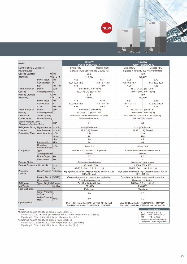
Model 33.5kW 40.0kW
PQRY-P300YLM-A PQRY-P350YLM-ANumber of HBC Controller Single HBC Double HBC Single HBC Double HBCPower Source 3-phase 4-wire 380-400-415 V 50/60 Hz 3-phase 4-wire 380-400-415 V 50/60 Hz Cooling Capacity *1 kW 33.5 40.0(Nominal) *1 BTU / h 114,300 136,500
Power Input kW 7.55 6.71 9.98 8.72Current Input A 12.7-12.1-11.6 11.3-10.7-10.3 16.8-16.0-15.4 14.7-13.9-13.4EER kW / kW 4.43 4.99 4.00 4.58
Temp. Range of Indoor W.B. 15.0~24.0°C (59~75°F) 15.0~24.0°C (59~75°F)Cooling Circulating Water °C 10.0~45.0°C (50~113°F) 10.0~45.0°C (50~113°F)Heating Capacity *2 kW 37.5 45.0(Nominal) *2 BTU / h 128,000 153,500
Power Input kW 7.13 6.79 8.87 8.25Current Input A 12.0-11.4-11.0 11.4-10.8-10.4 14.9-14.2-13.7 13.9-13.2-12.7COP kW / kW 5.25 5.52 5.07 5.45
Temp. Range of Indoor D.B. 15.0~27.0°C (59~81°F) 15.0~27.0°C (59~81°F)Heating Circulating Water °C 10.0~45.0°C (50~113°F) 10.0~45.0°C (50~113°F)Indoor Unit Total Capacity 50~150% of heat source unit capacity 50~150% of heat source unit capacityConnectable Model/Quantity WP15~WP50/3~30 WP15~WP50/4~35Sound Pressure Level (Measured in Anechoic Room) dBA 54 52
Refrigerant Piping High Pressure mm (in.) 19.05 (3/4) Brazed 22.2 (7/8) BrazedDiameter Low Pressure mm (in.) 22.2 (7/8) Brazed 28.58 (1-1/8) BrazedCirculating Water Water Flow Rate m3/h 5.76 7.20
L/min 96 120cfm 3.4 4.2
Pressure Drop kPa 24 44Operating Volume Range m3/h 3.0 ~ 7.2 4.5 ~ 11.6
Compressor Type Inverter scroll hermetic compressor Inverter scroll hermetic compressorStarting Method Inverter InverterMotor Output kW 7.7 9.5Case Heater kW – –
External Finish Galvanized steel sheets Galvanized steel sheetsExternal Dimension H x W x D mm 1,100 x 880 x 550 1,450 x 880 x 550
in. 43-5/16 x 34-11/16 x 21-11/16 57-1/8 x 34-11/16 x 21-11/16ProtectionDevices
High Pressure Protection High pressure sensor, High pressure switch at 4.15 MPa (601 psi)
High pressure sensor, high pressure switch at 4.15 MPa (601 psi)
Inverter Circuit (COMP.) Over-heat protection, over-current protection Over-heat protection, over-current protectionCompressor Over-heat protection Over-heat protection
Refrigerant Type x Original Charge R410A x 5.0 kg (12 lbs) R410A x 6.0 kg (14 lbs)Net Weight kg (lbs) 172 (380) 216 (477)Heat Exchanger Plate type Plate type
Water Volume in Plate L 5.0 5.0
Water Pressure Max. MPa 2.0 2.0
Optional Parts Main HBC controller: CMB-WP108, 1016V-GA1Sub HBC controller: CMB-WP108, 1016V-GB1
Main HBC controller: CMB-WP108, 1016V-GA1Sub HBC controller: CMB-WP108, 1016V-GB1
Notes:*1. Nominal cooling conditions (subject to JIS B8615-2) Indoor: 27°CD.B./19°CW.B. (81°FD.B./66°FW.B.), Water temperature: 30°C (86°F) Pipe length: 7.5 m (24-9/16 ft.), Level diff erence: 0 m (0 ft.)*2. Nominal heating conditions (subject to JIS B8615-2) Indoor: 20°CD.B. (68°FD.B.), Water temperature: 20°C (68°FD.B.) Pipe length: 7.5 m (24-9/16 ft.), Level difference: 0 m (0 ft.)
Unit converter
BTU / h =kW × 3,412cfm =m3 / min × 35.31lbs =kg / 0.4536*Above specification data is subject to rounding variation.
NEW
27
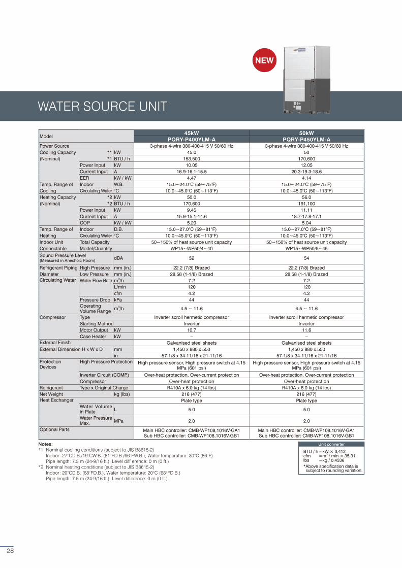
Model 45kW 50kW
PQRY-P400YLM-A PQRY-P450YLM-APower Source 3-phase 4-wire 380-400-415 V 50/60 Hz 3-phase 4-wire 380-400-415 V 50/60 HzCooling Capacity *1 kW 45.0 50(Nominal) *1 BTU / h 153,500 170,600
Power Input kW 10.05 12.05Current Input A 16.9-16.1-15.5 20.3-19.3-18.6EER kW / kW 4.47 4.14
Temp. Range of Indoor W.B. 15.0~24.0°C (59~75°F) 15.0~24.0°C (59~75°F)Cooling Circulating Water °C 10.0~45.0°C (50~113°F) 10.0~45.0°C (50~113°F)Heating Capacity *2 kW 50.0 56.0(Nominal) *2 BTU / h 170,600 191,100
Power Input kW 9.45 11.11Current Input A 15.9-15.1-14.6 18.7-17.8-17.1COP kW / kW 5.29 5.04
Temp. Range of Indoor D.B. 15.0~27.0°C (59~81°F) 15.0~27.0°C (59~81°F)Heating Circulating Water °C 10.0~45.0°C (50~113°F) 10.0~45.0°C (50~113°F)Indoor Unit Total Capacity 50~150% of heat source unit capacity 50~150% of heat source unit capacityConnectable Model/Quantity WP15~WP50/4~40 WP15~WP50/5~45Sound Pressure Level (Measured in Anechoic Room) dBA 52 54
Refrigerant Piping High Pressure mm (in.) 22.2 (7/8) Brazed 22.2 (7/8) BrazedDiameter Low Pressure mm (in.) 28.58 (1-1/8) Brazed 28.58 (1-1/8) BrazedCirculating Water Water Flow Rate m3/h 7.2 7.2
L/min 120 120cfm 4.2 4.2
Pressure Drop kPa 44 44Operating Volume Range m3/h 4.5 ~ 11.6 4.5 ~ 11.6
Compressor Type Inverter scroll hermetic compressor Inverter scroll hermetic compressorStarting Method Inverter InverterMotor Output kW 10.7 11.6Case Heater kW – –
External Finish Galvanised steel sheets Galvanised steel sheetsExternal Dimension H x W x D mm 1,450 x 880 x 550 1,450 x 880 x 550
in. 57-1/8 x 34-11/16 x 21-11/16 57-1/8 x 34-11/16 x 21-11/16ProtectionDevices
High Pressure Protection High pressure sensor, High pressure switch at 4.15 MPa (601 psi)
High pressure sensor, High pressure switch at 4.15 MPa (601 psi)
Inverter Circuit (COMP.) Over-heat protection, Over-current protection Over-heat protection, Over-current protectionCompressor Over-heat protection Over-heat protection
Refrigerant Type x Original Charge R410A x 6.0 kg (14 lbs) R410A x 6.0 kg (14 lbs)Net Weight kg (lbs) 216 (477) 216 (477)Heat Exchanger Plate type Plate type
Water Volume in Plate L 5.0 5.0
Water Pressure Max. MPa 2.0 2.0
Optional Parts Main HBC controller: CMB-WP108,1016V-GA1Sub HBC controller: CMB-WP108,1016V-GB1
Main HBC controller: CMB-WP108,1016V-GA1Sub HBC controller: CMB-WP108,1016V-GB1
WATER SOURCE UNIT
Notes:*1. Nominal cooling conditions (subject to JIS B8615-2) Indoor: 27°CD.B./19°CW.B. (81°FD.B./66°FW.B.), Water temperature: 30°C (86°F) Pipe length: 7.5 m (24-9/16 ft.), Level diff erence: 0 m (0 ft.)*2. Nominal heating conditions (subject to JIS B8615-2) Indoor: 20°CD.B. (68°FD.B.), Water temperature: 20°C (68°FD.B.) Pipe length: 7.5 m (24-9/16 ft.), Level difference: 0 m (0 ft.)
Unit converter
BTU / h =kW × 3,412cfm =m3 / min × 35.31lbs =kg / 0.4536*Above specification data is subject to rounding variation.
NEW
28
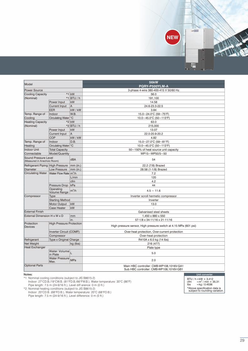
Model 56kW
PQRY-P500YLM-APower Source 3-phase 4-wire 380-400-415 V 50/60 HzCooling Capacity *1 kW 56.0(Nominal) *1 BTU / h 191,100
Power Input kW 14.58Current Input A 24.6-23.3-22.5EER kW / kW 3.84
Temp. Range of Indoor W.B. 15.0~24.0°C (59~75°F)Cooling Circulating Water °C 10.0~45.0°C (50~113°F)Heating Capacity *2 kW 63.0(Nominal) *2 BTU / h 215,000
Power Input kW 13.07Current Input A 22.0-20.9-20.2COP kW / kW 4.82
Temp. Range of Indoor D.B. 15.0~27.0°C (59~81°F)Heating Circulating Water °C 10.0~45.0°C (50~113°F)Indoor Unit Total Capacity 50~150% of heat source unit capacityConnectable Model/Quantity WP15~WP50/5~50Sound Pressure Level (Measured in Anechoic Room) dBA 54
Refrigerant Piping High Pressure mm (in.) 22.2 (7/8) BrazedDiameter Low Pressure mm (in.) 28.58 (1-1/8) BrazedCirculating Water Water Flow Rate m3/h 7.2
L/min 120cfm 4.2
Pressure Drop kPa 44Operating Volume Range m3/h 4.5 ~ 11.6
Compressor Type Inverter scroll hermetic compressorStarting Method InverterMotor Output kW 13.0Case Heater kW –
External Finish Galvanised steel sheetsExternal Dimension H x W x D mm 1,450 x 880 x 550
in. 57-1/8 x 34-11/16 x 21-11/16ProtectionDevices
High Pressure ProtectionHigh pressure sensor, High pressure switch at 4.15 MPa (601 psi)
Inverter Circuit (COMP.) Over-heat protection, Over-current protectionCompressor Over-heat protection
Refrigerant Type x Original Charge R410A x 6.0 kg (14 lbs)Net Weight kg (lbs) 216 (477)Heat Exchanger Plate type
Water Volume in Plate L 5.0
Water Pressure Max. MPa 2.0
Optional Parts Main HBC controller: CMB-WP108,1016V-GA1Sub HBC controller: CMB-WP108,1016V-GB1
Notes:*1. Nominal cooling conditions (subject to JIS B8615-2) Indoor: 27°CD.B./19°CW.B. (81°FD.B./66°FW.B.), Water temperature: 30°C (86°F) Pipe length: 7.5 m (24-9/16 ft.), Level diff erence: 0 m (0 ft.)*2. Nominal heating conditions (subject to JIS B8615-2) Indoor: 20°CD.B. (68°FD.B.), Water temperature: 20°C (68°FD.B.) Pipe length: 7.5 m (24-9/16 ft.), Level difference: 0 m (0 ft.)
Unit converter
BTU / h =kW × 3,412cfm =m3 / min × 35.31lbs =kg / 0.4536*Above specification data is subject to rounding variation.
NEW
29
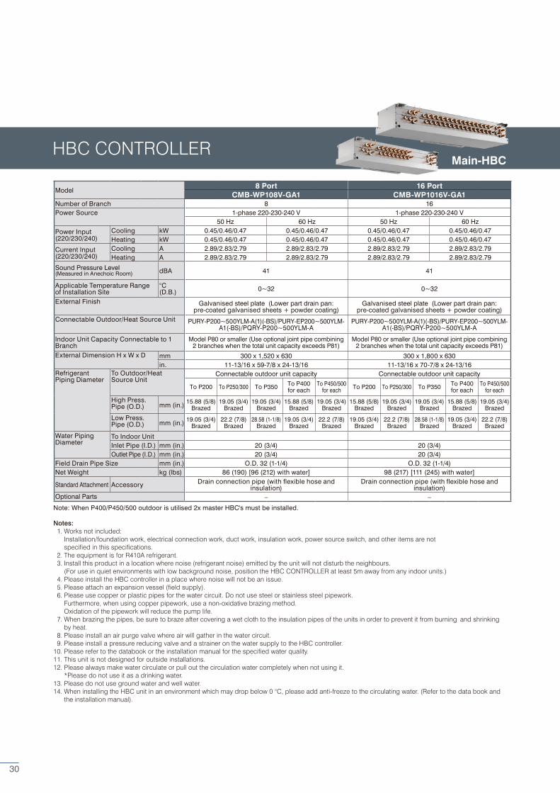
Model 8 Port 16 Port
CMB-WP108V-GA1 CMB-WP1016V-GA1Number of Branch 8 16Power Source 1-phase 220-230-240 V 1-phase 220-230-240 V
50 Hz 60 Hz 50 Hz 60 Hz
Power Input(220/230/240)
Cooling kW 0.45/0.46/0.47 0.45/0.46/0.47 0.45/0.46/0.47 0.45/0.46/0.47Heating kW 0.45/0.46/0.47 0.45/0.46/0.47 0.45/0.46/0.47 0.45/0.46/0.47
Current Input(220/230/240)
Cooling A 2.89/2.83/2.79 2.89/2.83/2.79 2.89/2.83/2.79 2.89/2.83/2.79Heating A 2.89/2.83/2.79 2.89/2.83/2.79 2.89/2.83/2.79 2.89/2.83/2.79
Sound Pressure Level (Measured in Anechoic Room) dBA 41 41
Applicable Temperature Range of Installation Site
°C (D.B.) 0~32 0~32
External Finish Galvanised steel plate (Lower part drain pan: pre-coated galvanised sheets + powder coating)
Galvanised steel plate (Lower part drain pan: pre-coated galvanised sheets + powder coating)
Connectable Outdoor/Heat Source Unit PURY-P200~500YLM-A(1)(-BS)/PURY-EP200~500YLM-A1(-BS)/PQRY-P200~500YLM-A
PURY-P200~500YLM-A(1)(-BS)/PURY-EP200~500YLM-A1(-BS)/PQRY-P200~500YLM-A
Indoor Unit Capacity Connectable to 1 Branch
Model P80 or smaller (Use optional joint pipe combining 2 branches when the total unit capacity exceeds P81)
Model P80 or smaller (Use optional joint pipe combining 2 branches when the total unit capacity exceeds P81)
External Dimension H x W x D mm 300 x 1,520 x 630 300 x 1,800 x 630in. 11-13/16 x 59-7/8 x 24-13/16 11-13/16 x 70-7/8 x 24-13/16
Refrigerant Piping Diameter
To Outdoor/Heat Source Unit
Connectable outdoor unit capacity Connectable outdoor unit capacity
To P200 To P250/300 To P350 To P400for each
To P450/500for each To P200 To P250/300 To P350 To P400
for eachTo P450/500
for each
High Press. Pipe (O.D.) mm (in.) 15.88 (5/8)
Brazed19.05 (3/4)
Brazed19.05 (3/4)
Brazed15.88 (5/8)
Brazed19.05 (3/4)
Brazed15.88 (5/8)
Brazed19.05 (3/4)
Brazed19.05 (3/4)
Brazed15.88 (5/8)
Brazed19.05 (3/4)
Brazed
Low Press. Pipe (O.D.) mm (in.) 19.05 (3/4)
Brazed22.2 (7/8)
Brazed28.58 (1-1/8)
Brazed19.05 (3/4)
Brazed22.2 (7/8)
Brazed19.05 (3/4)
Brazed22.2 (7/8)
Brazed28.58 (1-1/8)
Brazed19.05 (3/4)
Brazed22.2 (7/8)
Brazed
Water Piping Diameter
To Indoor UnitInlet Pipe (I.D.) mm (in.) 20 (3/4) 20 (3/4)Outlet Pipe (I.D.) mm (in.) 20 (3/4) 20 (3/4)
Field Drain Pipe Size mm (in.) O.D. 32 (1-1/4) O.D. 32 (1-1/4)Net Weight kg (lbs) 86 (190) [96 (212) with water] 98 (217) [111 (245) with water]
Standard Attachment Accessory Drain connection pipe (with flexible hose and insulation)
Drain connection pipe (with flexible hose and insulation)
Optional Parts – –
Notes: 1. Works not included: Installation/foundation work, electrical connection work, duct work, insulation work, power source switch, and other items are not specified in this specifications. 2. The equipment is for R410A refrigerant. 3. Install this product in a location where noise (refrigerant noise) emitted by the unit will not disturb the neighbours. (For use in quiet environments with low background noise, position the HBC CONTROLLER at least 5m away from any indoor units.) 4. Please install the HBC controller in a place where noise will not be an issue. 5. Please attach an expansion vessel (field supply). 6. Please use copper or plastic pipes for the water circuit. Do not use steel or stainless steel pipework. Furthermore, when using copper pipework, use a non-oxidative brazing method. Oxidation of the pipework will reduce the pump life. 7. When brazing the pipes, be sure to braze after covering a wet cloth to the insulation pipes of the units in order to prevent it from burning and shrinking by heat. 8. Please install an air purge valve where air will gather in the water circuit. 9. Please install a pressure reducing valve and a strainer on the water supply to the HBC controller.10. Please refer to the databook or the installation manual for the specified water quality.11. This unit is not designed for outside installations.12. Please always make water circulate or pull out the circulation water completely when not using it. *Please do not use it as a drinking water.13. Please do not use ground water and well water.14. When installing the HBC unit in an environment which may drop below 0 °C, please add anti-freeze to the circulating water. (Refer to the data book and the installation manual).
Note: When P400/P450/500 outdoor is utilised 2x master HBC's must be installed.
HBC CONTROLLERMain-HBC
30
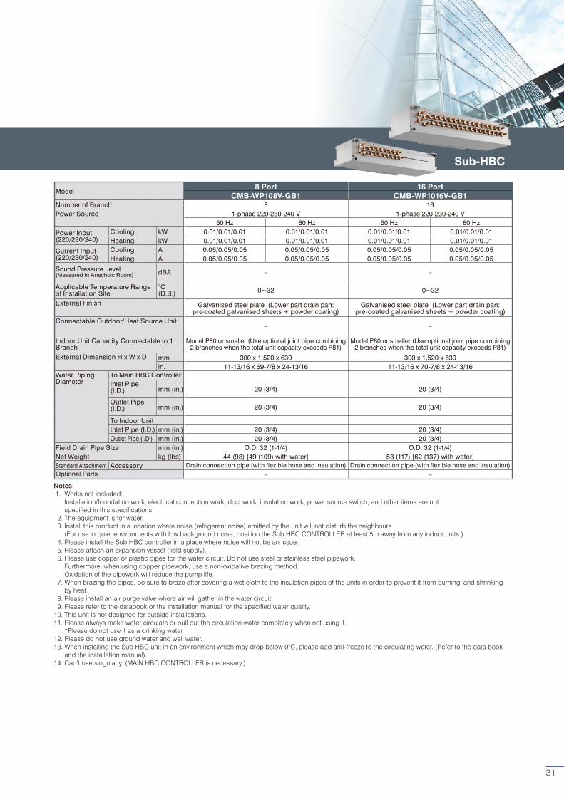
Model 8 Port 16 Port
CMB-WP108V-GB1 CMB-WP1016V-GB1Number of Branch 8 16Power Source 1-phase 220-230-240 V 1-phase 220-230-240 V
50 Hz 60 Hz 50 Hz 60 Hz
Power Input(220/230/240)
Cooling kW 0.01/0.01/0.01 0.01/0.01/0.01 0.01/0.01/0.01 0.01/0.01/0.01Heating kW 0.01/0.01/0.01 0.01/0.01/0.01 0.01/0.01/0.01 0.01/0.01/0.01
Current Input(220/230/240)
Cooling A 0.05/0.05/0.05 0.05/0.05/0.05 0.05/0.05/0.05 0.05/0.05/0.05Heating A 0.05/0.05/0.05 0.05/0.05/0.05 0.05/0.05/0.05 0.05/0.05/0.05
Sound Pressure Level (Measured in Anechoic Room) dBA – –
Applicable Temperature Range of Installation Site
°C (D.B.) 0~32 0~32
External Finish Galvanised steel plate (Lower part drain pan: pre-coated galvanised sheets + powder coating)
Galvanised steel plate (Lower part drain pan: pre-coated galvanised sheets + powder coating)
Connectable Outdoor/Heat Source Unit– –
Indoor Unit Capacity Connectable to 1 Branch
Model P80 or smaller (Use optional joint pipe combining 2 branches when the total unit capacity exceeds P81)
Model P80 or smaller (Use optional joint pipe combining 2 branches when the total unit capacity exceeds P81)
External Dimension H x W x D mm 300 x 1,520 x 630 300 x 1,520 x 630in. 11-13/16 x 59-7/8 x 24-13/16 11-13/16 x 70-7/8 x 24-13/16
Water Piping Diameter
To Main HBC ControllerInlet Pipe(I.D.) mm (in.) 20 (3/4) 20 (3/4)
Outlet Pipe(I.D.) mm (in.) 20 (3/4) 20 (3/4)
To Indoor UnitInlet Pipe (I.D.) mm (in.) 20 (3/4) 20 (3/4)Outlet Pipe (I.D.) mm (in.) 20 (3/4) 20 (3/4)
Field Drain Pipe Size mm (in.) O.D. 32 (1-1/4) O.D. 32 (1-1/4)Net Weight kg (lbs) 44 (98) [49 (109) with water] 53 (117) [62 (137) with water]Standard Attachment Accessory Drain connection pipe (with flexible hose and insulation) Drain connection pipe (with flexible hose and insulation)Optional Parts – –
Notes: 1. Works not included: Installation/foundation work, electrical connection work, duct work, insulation work, power source switch, and other items are not specified in this specifications. 2. The equipment is for water. 3. Install this product in a location where noise (refrigerant noise) emitted by the unit will not disturb the neighbours. (For use in quiet environments with low background noise, position the Sub HBC CONTROLLER at least 5m away from any indoor units.) 4. Please install the Sub HBC controller in a place where noise will not be an issue. 5. Please attach an expansion vessel (field supply). 6. Please use copper or plastic pipes for the water circuit. Do not use steel or stainless steel pipework. Furthermore, when using copper pipework, use a non-oxidative brazing method. Oxidation of the pipework will reduce the pump life. 7. When brazing the pipes, be sure to braze after covering a wet cloth to the insulation pipes of the units in order to prevent it from burning and shrinking by heat. 8. Please install an air purge valve where air will gather in the water circuit. 9. Please refer to the databook or the installation manual for the specified water quality.10. This unit is not designed for outside installations.11. Please always make water circulate or pull out the circulation water completely when not using it. *Please do not use it as a drinking water.12. Please do not use ground water and well water.13. When installing the Sub HBC unit in an environment which may drop below 0°C, please add anti-freeze to the circulating water. (Refer to the data book and the installation manual).14. Can’t use singularly. (MAIN HBC CONTROLLER is necessary.)
Sub-HBC
31
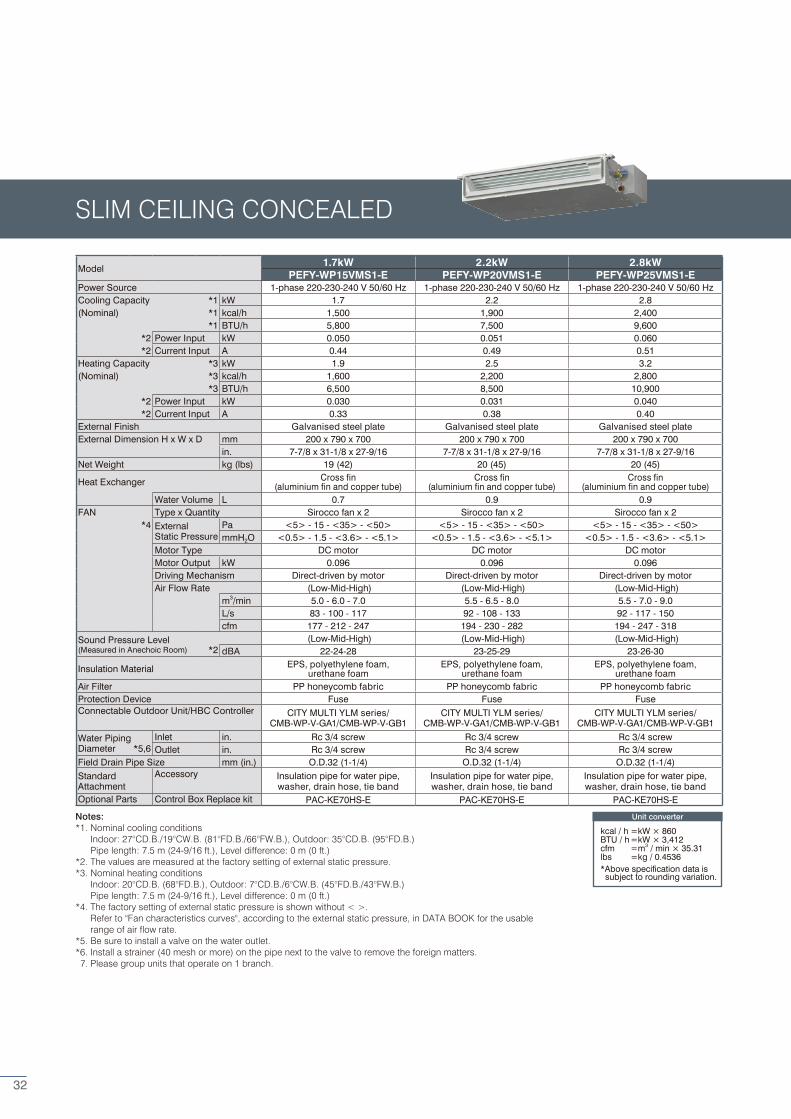
Model 1.7kW 2.2kW 2.8kW
PEFY-WP15VMS1-E PEFY-WP20VMS1-E PEFY-WP25VMS1-EPower Source 1-phase 220-230-240 V 50/60 Hz 1-phase 220-230-240 V 50/60 Hz 1-phase 220-230-240 V 50/60 HzCooling Capacity *1 kW 1.7 2.2 2.8(Nominal) *1 kcal/h 1,500 1,900 2,400
*1 BTU/h 5,800 7,500 9,600*2 Power Input kW 0.050 0.051 0.060*2 Current Input A 0.44 0.49 0.51
Heating Capacity *3 kW 1.9 2.5 3.2(Nominal) *3 kcal/h 1,600 2,200 2,800
*3 BTU/h 6,500 8,500 10,900*2 Power Input kW 0.030 0.031 0.040*2 Current Input A 0.33 0.38 0.40
External Finish Galvanised steel plate Galvanised steel plate Galvanised steel plateExternal Dimension H x W x D mm 200 x 790 x 700 200 x 790 x 700 200 x 790 x 700
in. 7-7/8 x 31-1/8 x 27-9/16 7-7/8 x 31-1/8 x 27-9/16 7-7/8 x 31-1/8 x 27-9/16Net Weight kg (lbs) 19 (42) 20 (45) 20 (45)
Heat Exchanger Cross fin (aluminium fin and copper tube)
Cross fin (aluminium fin and copper tube)
Cross fin (aluminium fin and copper tube)
Water Volume L 0.7 0.9 0.9FAN Type x Quantity Sirocco fan x 2 Sirocco fan x 2 Sirocco fan x 2
*4 ExternalStatic Pressure
Pa <5> - 15 - <35> - <50> <5> - 15 - <35> - <50> <5> - 15 - <35> - <50>mmH2O <0.5> - 1.5 - <3.6> - <5.1> <0.5> - 1.5 - <3.6> - <5.1> <0.5> - 1.5 - <3.6> - <5.1>
Motor Type DC motor DC motor DC motorMotor Output kW 0.096 0.096 0.096Driving Mechanism Direct-driven by motor Direct-driven by motor Direct-driven by motorAir Flow Rate (Low-Mid-High) (Low-Mid-High) (Low-Mid-High)
m3/min 5.0 - 6.0 - 7.0 5.5 - 6.5 - 8.0 5.5 - 7.0 - 9.0L/s 83 - 100 - 117 92 - 108 - 133 92 - 117 - 150cfm 177 - 212 - 247 194 - 230 - 282 194 - 247 - 318
Sound Pressure Level (Low-Mid-High) (Low-Mid-High) (Low-Mid-High)(Measured in Anechoic Room) *2 dBA 22-24-28 23-25-29 23-26-30
Insulation Material EPS, polyethylene foam, urethane foam
EPS, polyethylene foam, urethane foam
EPS, polyethylene foam, urethane foam
Air Filter PP honeycomb fabric PP honeycomb fabric PP honeycomb fabricProtection Device Fuse Fuse FuseConnectable Outdoor Unit/HBC Controller CITY MULTI YLM series/
CMB-WP-V-GA1/CMB-WP-V-GB1CITY MULTI YLM series/
CMB-WP-V-GA1/CMB-WP-V-GB1CITY MULTI YLM series/
CMB-WP-V-GA1/CMB-WP-V-GB1
Water PipingDiameter *5,6
Inlet in. Rc 3/4 screw Rc 3/4 screw Rc 3/4 screwOutlet in. Rc 3/4 screw Rc 3/4 screw Rc 3/4 screw
Field Drain Pipe Size mm (in.) O.D.32 (1-1/4) O.D.32 (1-1/4) O.D.32 (1-1/4)StandardAttachment
Accessory Insulation pipe for water pipe, washer, drain hose, tie band
Insulation pipe for water pipe, washer, drain hose, tie band
Insulation pipe for water pipe, washer, drain hose, tie band
Optional Parts Control Box Replace kit PAC-KE70HS-E PAC-KE70HS-E PAC-KE70HS-E
Notes:*1. Nominal cooling conditions Indoor: 27°CD.B./19°CW.B. (81°FD.B./66°FW.B.), Outdoor: 35°CD.B. (95°FD.B.) Pipe length: 7.5 m (24-9/16 ft.), Level difference: 0 m (0 ft.)*2. The values are measured at the factory setting of external static pressure.*3. Nominal heating conditions Indoor: 20°CD.B. (68°FD.B.), Outdoor: 7°CD.B./6°CW.B. (45°FD.B./43°FW.B.) Pipe length: 7.5 m (24-9/16 ft.), Level difference: 0 m (0 ft.)*4. The factory setting of external static pressure is shown without < >. Refer to "Fan characteristics curves", according to the external static pressure, in DATA BOOK for the usable range of air flow rate.*5. Be sure to install a valve on the water outlet.*6. Install a strainer (40 mesh or more) on the pipe next to the valve to remove the foreign matters. 7. Please group units that operate on 1 branch.
Unit converter
kcal / h =kW × 860BTU / h =kW × 3,412cfm =m3 / min × 35.31lbs =kg / 0.4536*Above specification data is subject to rounding variation.
SLIM CEILING CONCEALED
32
Notes:*1. Nominal cooling conditions Indoor: 27°CD.B./19°CW.B. (81°FD.B./66°FW.B.), Outdoor: 35°CD.B. (95°FD.B.) Pipe length: 7.5 m (24-9/16 ft.), Level difference: 0 m (0 ft.)*2. The values are measured at the factory setting of external static pressure.*3. Nominal heating conditions Indoor: 20°CD.B. (68°FD.B.), Outdoor: 7°CD.B./6°CW.B. (45°FD.B./43°FW.B.) Pipe length: 7.5 m (24-9/16 ft.), Level difference: 0 m (0 ft.)*4. The factory setting of external static pressure is shown without < >. Refer to "Fan characteristics curves", according to the external static pressure, in DATA BOOK for the usable range of air flow rate.*5. Be sure to install a valve on the water outlet.*6. Install a strainer (40 mesh or more) on the pipe next to the valve to remove the foreign matters. 7. Please group units that operate on 1 branch.
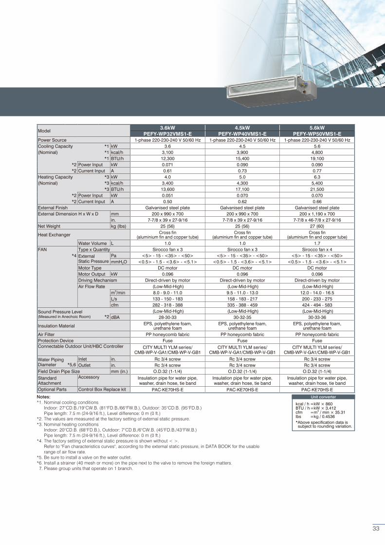
Model 3.6kW 4.5kW 5.6kW
PEFY-WP32VMS1-E PEFY-WP40VMS1-E PEFY-WP50VMS1-EPower Source 1-phase 220-230-240 V 50/60 Hz 1-phase 220-230-240 V 50/60 Hz 1-phase 220-230-240 V 50/60 HzCooling Capacity *1 kW 3.6 4.5 5.6(Nominal) *1 kcal/h 3,100 3,900 4,800
*1 BTU/h 12,300 15,400 19,100*2 Power Input kW 0.071 0.090 0.090*2 Current Input A 0.61 0.73 0.77
Heating Capacity *3 kW 4.0 5.0 6.3(Nominal) *3 kcal/h 3,400 4,300 5,400
*3 BTU/h 13,600 17,100 21,500*2 Power Input kW 0.051 0.070 0.070*2 Current Input A 0.50 0.62 0.66
External Finish Galvanised steel plate Galvanised steel plate Galvanised steel plateExternal Dimension H x W x D mm 200 x 990 x 700 200 x 990 x 700 200 x 1,190 x 700
in. 7-7/8 x 39 x 27-9/16 7-7/8 x 39 x 27-9/16 7-7/8 x 46-7/8 x 27-9/16Net Weight kg (lbs) 25 (56) 25 (56) 27 (60)
Heat Exchanger Cross fin (aluminium fin and copper tube)
Cross fin (aluminium fin and copper tube)
Cross fin (aluminium fin and copper tube)
Water Volume L 1.0 1.0 1.7FAN Type x Quantity Sirocco fan x 3 Sirocco fan x 3 Sirocco fan x 4
*4 ExternalStatic Pressure
Pa <5> - 15 - <35> - <50> <5> - 15 - <35> - <50> <5> - 15 - <35> - <50>mmH2O <0.5> - 1.5 - <3.6> - <5.1> <0.5> - 1.5 - <3.6> - <5.1> <0.5> - 1.5 - <3.6> - <5.1>
Motor Type DC motor DC motor DC motorMotor Output kW 0.096 0.096 0.096Driving Mechanism Direct-driven by motor Direct-driven by motor Direct-driven by motorAir Flow Rate (Low-Mid-High) (Low-Mid-High) (Low-Mid-High)
m3/min 8.0 - 9.0 - 11.0 9.5 - 11.0 - 13.0 12.0 - 14.0 - 16.5L/s 133 - 150 - 183 158 - 183 - 217 200 - 233 - 275cfm 282 - 318 - 388 335 - 388 - 459 424 - 494 - 583
Sound Pressure Level (Low-Mid-High) (Low-Mid-High) (Low-Mid-High)(Measured in Anechoic Room) *2 dBA 28-30-33 30-32-35 30-33-36
Insulation Material EPS, polyethylene foam, urethane foam
EPS, polyethylene foam, urethane foam
EPS, polyethylene foam, urethane foam
Air Filter PP honeycomb fabric PP honeycomb fabric PP honeycomb fabricProtection Device Fuse Fuse FuseConnectable Outdoor Unit/HBC Controller CITY MULTI YLM series/
CMB-WP-V-GA1/CMB-WP-V-GB1CITY MULTI YLM series/
CMB-WP-V-GA1/CMB-WP-V-GB1CITY MULTI YLM series/
CMB-WP-V-GA1/CMB-WP-V-GB1
Water PipingDiameter *5,6
Inlet in. Rc 3/4 screw Rc 3/4 screw Rc 3/4 screwOutlet in. Rc 3/4 screw Rc 3/4 screw Rc 3/4 screw
Field Drain Pipe Size mm (in.) O.D.32 (1-1/4) O.D.32 (1-1/4) O.D.32 (1-1/4)StandardAttachment
Accessory Insulation pipe for water pipe, washer, drain hose, tie band
Insulation pipe for water pipe, washer, drain hose, tie band
Insulation pipe for water pipe, washer, drain hose, tie band
Optional Parts Control Box Replace kit PAC-KE70HS-E PAC-KE70HS-E PAC-KE70HS-E
Unit converter
kcal / h =kW × 860BTU / h =kW × 3,412cfm =m3 / min × 35.31lbs =kg / 0.4536*Above specification data is subject to rounding variation.
33
Unit converter
kcal / h =kW × 860BTU / h =kW × 3,412cfm =m3 / min × 35.31lbs =kg / 0.4536*Above specification data is subject to rounding variation.
Notes:*1. Nominal cooling conditions Indoor: 27 °CD.B./19 °CW.B. (81 °FD.B./66 °FW.B.), Outdoor: 35 °CD.B. (95 °FD.B.) Pipe length: 7.5 m (24-9/16 ft.), Level difference: 0 m (0 ft.)*2. The values are measured at the factory setting of external static pressure.*3. Nominal heating conditions Indoor: 20 °CD.B. (68 °FD.B.), Outdoor: 7 °CD.B./6 °CW.B. (45 °FD.B./43 °FW.B.) Pipe length: 7.5 m (24-9/16 ft.), Level difference: 0 m (0 ft.)*4. The factory setting of external static pressure is shown without < >. Refer to "Fan characteristics curves", according to the external static pressure, in DATA BOOK for the usable range of air flow rate.*5. Be sure to install a valve on the water outlet.*6. Install a strainer (40 mesh or more) on the pipe next to the valve to remove the foreign matters. 7. Group units that operate on 1 branch.
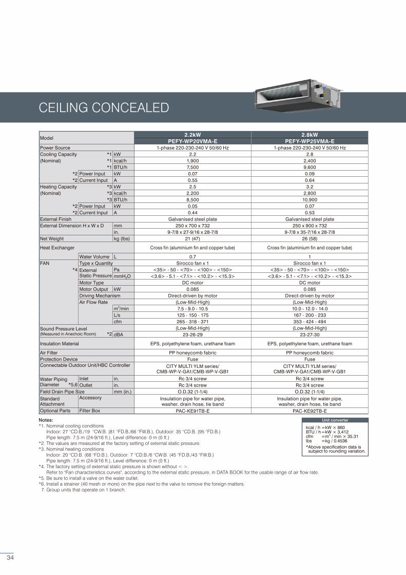
CEILING CONCEALED
Model 2.2kW 2.8kW
PEFY-WP20VMA-E PEFY-WP25VMA-EPower Source 1-phase 220-230-240 V 50/60 Hz 1-phase 220-230-240 V 50/60 HzCooling Capacity *1 kW 2.2 2.8(Nominal) *1 kcal/h 1,900 2,400
*1 BTU/h 7,500 9,600*2 Power Input kW 0.07 0.09*2 Current Input A 0.55 0.64
Heating Capacity *3 kW 2.5 3.2(Nominal) *3 kcal/h 2,200 2,800
*3 BTU/h 8,500 10,900*2 Power Input kW 0.05 0.07*2 Current Input A 0.44 0.53
External Finish Galvanised steel plate Galvanised steel plateExternal Dimension H x W x D mm 250 x 700 x 732 250 x 900 x 732
in. 9-7/8 x 27-9/16 x 28-7/8 9-7/8 x 35-7/16 x 28-7/8Net Weight kg (lbs) 21 (47) 26 (58)
Heat Exchanger Cross fin (aluminium fin and copper tube) Cross fin (aluminium fin and copper tube)
Water Volume L 0.7 1FAN Type x Quantity Sirocco fan x 1 Sirocco fan x 1
*4 ExternalStatic Pressure
Pa <35> - 50 - <70> - <100> - <150> <35> - 50 - <70> - <100> - <150>mmH2O <3.6> - 5.1 - <7.1> - <10.2> - <15.3> <3.6> - 5.1 - <7.1> - <10.2> - <15.3>
Motor Type DC motor DC motorMotor Output kW 0.085 0.085Driving Mechanism Direct-driven by motor Direct-driven by motorAir Flow Rate (Low-Mid-High) (Low-Mid-High)
m3/min 7.5 - 9.0 - 10.5 10.0 - 12.0 - 14.0L/s 125 - 150 - 175 167 - 200 - 233cfm 265 - 318 - 371 353 - 424 - 494
Sound Pressure Level (Low-Mid-High) (Low-Mid-High)(Measured in Anechoic Room) *2 dBA 23-26-29 23-27-30
Insulation Material EPS, polyethylene foam, urethane foam EPS, polyethylene foam, urethane foam
Air Filter PP honeycomb fabric PP honeycomb fabricProtection Device Fuse FuseConnectable Outdoor Unit/HBC Controller CITY MULTI YLM series/
CMB-WP-V-GA1/CMB-WP-V-GB1CITY MULTI YLM series/
CMB-WP-V-GA1/CMB-WP-V-GB1
Water PipingDiameter *5,6
Inlet in. Rc 3/4 screw Rc 3/4 screwOutlet in. Rc 3/4 screw Rc 3/4 screw
Field Drain Pipe Size mm (in.) O.D.32 (1-1/4) O.D.32 (1-1/4)StandardAttachment
Accessory Insulation pipe for water pipe, washer, drain hose, tie band
Insulation pipe for water pipe, washer, drain hose, tie band
Optional Parts Filter Box PAC-KE91TB-E PAC-KE92TB-E
34
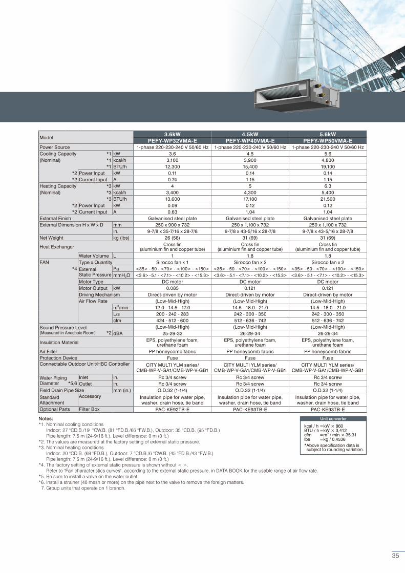
Unit converter
kcal / h =kW × 860BTU / h =kW × 3,412cfm =m3 / min × 35.31lbs =kg / 0.4536*Above specification data is subject to rounding variation.
Notes:*1. Nominal cooling conditions Indoor: 27 °CD.B./19 °CW.B. (81 °FD.B./66 °FW.B.), Outdoor: 35 °CD.B. (95 °FD.B.) Pipe length: 7.5 m (24-9/16 ft.), Level difference: 0 m (0 ft.)*2. The values are measured at the factory setting of external static pressure.*3. Nominal heating conditions Indoor: 20 °CD.B. (68 °FD.B.), Outdoor: 7 °CD.B./6 °CW.B. (45 °FD.B./43 °FW.B.) Pipe length: 7.5 m (24-9/16 ft.), Level difference: 0 m (0 ft.)*4. The factory setting of external static pressure is shown without < >. Refer to "Fan characteristics curves", according to the external static pressure, in DATA BOOK for the usable range of air flow rate.*5. Be sure to install a valve on the water outlet.*6. Install a strainer (40 mesh or more) on the pipe next to the valve to remove the foreign matters. 7. Group units that operate on 1 branch.
Model 3.6kW 4.5kW 5.6kW
PEFY-WP32VMA-E PEFY-WP40VMA-E PEFY-WP50VMA-EPower Source 1-phase 220-230-240 V 50/60 Hz 1-phase 220-230-240 V 50/60 Hz 1-phase 220-230-240 V 50/60 HzCooling Capacity *1 kW 3.6 4.5 5.6(Nominal) *1 kcal/h 3,100 3,900 4,800
*1 BTU/h 12,300 15,400 19,100*2 Power Input kW 0.11 0.14 0.14*2 Current Input A 0.74 1.15 1.15
Heating Capacity *3 kW 4 5 6.3(Nominal) *3 kcal/h 3,400 4,300 5,400
*3 BTU/h 13,600 17,100 21,500*2 Power Input kW 0.09 0.12 0.12*2 Current Input A 0.63 1.04 1.04
External Finish Galvanised steel plate Galvanised steel plate Galvanised steel plateExternal Dimension H x W x D mm 250 x 900 x 732 250 x 1,100 x 732 250 x 1,100 x 732
in. 9-7/8 x 35-7/16 x 28-7/8 9-7/8 x 43-5/16 x 28-7/8 9-7/8 x 43-5/16 x 28-7/8Net Weight kg (lbs) 26 (58) 31 (69) 31 (69)
Heat Exchanger Cross fin (aluminium fin and copper tube)
Cross fin (aluminium fin and copper tube)
Cross fin (aluminium fin and copper tube)
Water Volume L 1 1.8 1.8FAN Type x Quantity Sirocco fan x 1 Sirocco fan x 2 Sirocco fan x 2
*4 ExternalStatic Pressure
Pa <35> - 50 - <70> - <100> - <150> <35> - 50 - <70> - <100> - <150> <35> - 50 - <70> - <100> - <150>mmH2O <3.6> - 5.1 - <7.1> - <10.2> - <15.3> <3.6> - 5.1 - <7.1> - <10.2> - <15.3> <3.6> - 5.1 - <7.1> - <10.2> - <15.3>
Motor Type DC motor DC motor DC motorMotor Output kW 0.085 0.121 0.121Driving Mechanism Direct-driven by motor Direct-driven by motor Direct-driven by motorAir Flow Rate (Low-Mid-High) (Low-Mid-High) (Low-Mid-High)
m3/min 12.0 - 14.5 - 17.0 14.5 - 18.0 - 21.0 14.5 - 18.0 - 21.0L/s 200 - 242 - 283 242 - 300 - 350 242 - 300 - 350cfm 424 - 512 - 600 512 - 636 - 742 512 - 636 - 742
Sound Pressure Level (Low-Mid-High) (Low-Mid-High) (Low-Mid-High)(Measured in Anechoic Room) *2 dBA 25-29-32 26-29-34 26-29-34
Insulation Material EPS, polyethylene foam, urethane foam
EPS, polyethylene foam, urethane foam
EPS, polyethylene foam, urethane foam
Air Filter PP honeycomb fabric PP honeycomb fabric PP honeycomb fabricProtection Device Fuse Fuse FuseConnectable Outdoor Unit/HBC Controller CITY MULTI YLM series/
CMB-WP-V-GA1/CMB-WP-V-GB1CITY MULTI YLM series/
CMB-WP-V-GA1/CMB-WP-V-GB1CITY MULTI YLM series/
CMB-WP-V-GA1/CMB-WP-V-GB1
Water PipingDiameter *5,6
Inlet in. Rc 3/4 screw Rc 3/4 screw Rc 3/4 screwOutlet in. Rc 3/4 screw Rc 3/4 screw Rc 3/4 screw
Field Drain Pipe Size mm (in.) O.D.32 (1-1/4) O.D.32 (1-1/4) O.D.32 (1-1/4)StandardAttachment
Accessory Insulation pipe for water pipe, washer, drain hose, tie band
Insulation pipe for water pipe, washer, drain hose, tie band
Insulation pipe for water pipe, washer, drain hose, tie band
Optional Parts Filter Box PAC-KE92TB-E PAC-KE93TB-E PAC-KE93TB-E
35
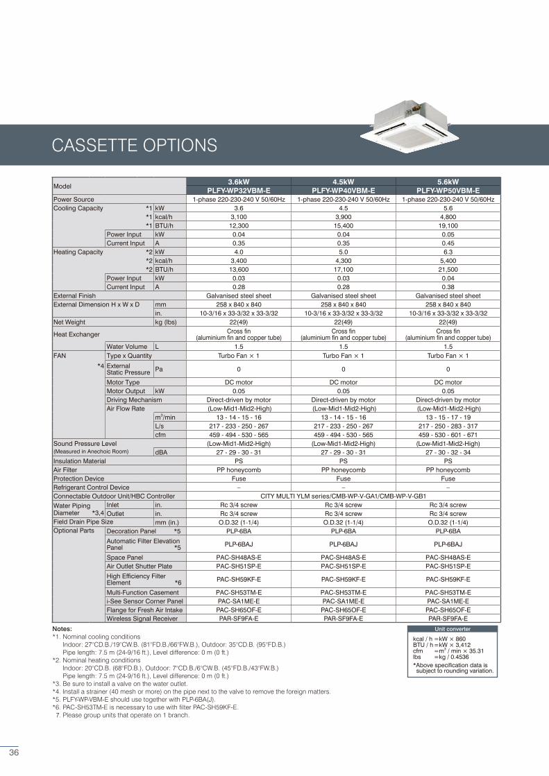
Model 3.6kW 4.5kW 5.6kW
PLFY-WP32VBM-E PLFY-WP40VBM-E PLFY-WP50VBM-EPower Source 1-phase 220-230-240 V 50/60Hz 1-phase 220-230-240 V 50/60Hz 1-phase 220-230-240 V 50/60HzCooling Capacity *1 kW 3.6 4.5 5.6
*1 kcal/h 3,100 3,900 4,800*1 BTU/h 12,300 15,400 19,100
Power Input kW 0.04 0.04 0.05Current Input A 0.35 0.35 0.45
Heating Capacity *2 kW 4.0 5.0 6.3*2 kcal/h 3,400 4,300 5,400*2 BTU/h 13,600 17,100 21,500
Power Input kW 0.03 0.03 0.04Current Input A 0.28 0.28 0.38
External Finish Galvanised steel sheet Galvanised steel sheet Galvanised steel sheetExternal Dimension H x W x D mm 258 x 840 x 840 258 x 840 x 840 258 x 840 x 840
in. 10-3/16 x 33-3/32 x 33-3/32 10-3/16 x 33-3/32 x 33-3/32 10-3/16 x 33-3/32 x 33-3/32Net Weight kg (lbs) 22(49) 22(49) 22(49)
Heat Exchanger Cross fin (aluminium fin and copper tube)
Cross fin (aluminium fin and copper tube)
Cross fin (aluminium fin and copper tube)
Water Volume L 1.5 1.5 1.5FAN Type x Quantity Turbo Fan × 1 Turbo Fan × 1 Turbo Fan × 1
*4 External Static Pressure Pa 0 0 0
Motor Type DC motor DC motor DC motorMotor Output kW 0.05 0.05 0.05Driving Mechanism Direct-driven by motor Direct-driven by motor Direct-driven by motorAir Flow Rate (Low-Mid1-Mid2-High) (Low-Mid1-Mid2-High) (Low-Mid1-Mid2-High)
m3/min 13 - 14 - 15 - 16 13 - 14 - 15 - 16 13 - 15 - 17 - 19L/s 217 - 233 - 250 - 267 217 - 233 - 250 - 267 217 - 250 - 283 - 317cfm 459 - 494 - 530 - 565 459 - 494 - 530 - 565 459 - 530 - 601 - 671
Sound Pressure Level (Low-Mid1-Mid2-High) (Low-Mid1-Mid2-High) (Low-Mid1-Mid2-High)(Measured in Anechoic Room) dBA 27 - 29 - 30 - 31 27 - 29 - 30 - 31 27 - 30 - 32 - 34Insulation Material PS PS PSAir Filter PP honeycomb PP honeycomb PP honeycombProtection Device Fuse Fuse FuseRefrigerant Control Device – – –Connectable Outdoor Unit/HBC Controller CITY MULTI YLM series/CMB-WP-V-GA1/CMB-WP-V-GB1Water PipingDiameter *3,4
Inlet in. Rc 3/4 screw Rc 3/4 screw Rc 3/4 screwOutlet in. Rc 3/4 screw Rc 3/4 screw Rc 3/4 screw
Field Drain Pipe Size mm (in.) O.D.32 (1-1/4) O.D.32 (1-1/4) O.D.32 (1-1/4)Optional Parts Decoration Panel *5 PLP-6BA PLP-6BA PLP-6BA
Automatic Filter Elevation Panel *5 PLP-6BAJ PLP-6BAJ PLP-6BAJ
Space Panel PAC-SH48AS-E PAC-SH48AS-E PAC-SH48AS-EAir Outlet Shutter Plate PAC-SH51SP-E PAC-SH51SP-E PAC-SH51SP-E
High Efficiency Filter Element *6 PAC-SH59KF-E PAC-SH59KF-E PAC-SH59KF-E
Multi-Function Casement PAC-SH53TM-E PAC-SH53TM-E PAC-SH53TM-Ei-See Sensor Corner Panel PAC-SA1ME-E PAC-SA1ME-E PAC-SA1ME-EFlange for Fresh Air Intake PAC-SH65OF-E PAC-SH65OF-E PAC-SH65OF-EWireless Signal Receiver PAR-SF9FA-E PAR-SF9FA-E PAR-SF9FA-E
Notes:*1. Nominal cooling conditions Indoor: 27°CD.B./19°CW.B. (81°FD.B./66°FW.B.), Outdoor: 35°CD.B. (95°FD.B.) Pipe length: 7.5 m (24-9/16 ft.), Level difference: 0 m (0 ft.)*2. Nominal heating conditions Indoor: 20°CD.B. (68°FD.B.), Outdoor: 7°CD.B./6°CW.B. (45°FD.B./43°FW.B.) Pipe length: 7.5 m (24-9/16 ft.), Level difference: 0 m (0 ft.)*3. Be sure to install a valve on the water outlet.*4. Install a strainer (40 mesh or more) on the pipe next to the valve to remove the foreign matters.*5. PLFY-WP-VBM-E should use together with PLP-6BA(J).*6. PAC-SH53TM-E is necessary to use with filter PAC-SH59KF-E. 7. Please group units that operate on 1 branch.
CASSETTE OPTIONS
Unit converter
kcal / h =kW × 860BTU / h =kW × 3,412cfm =m3 / min × 35.31lbs =kg / 0.4536*Above specification data is subject to rounding variation.
36
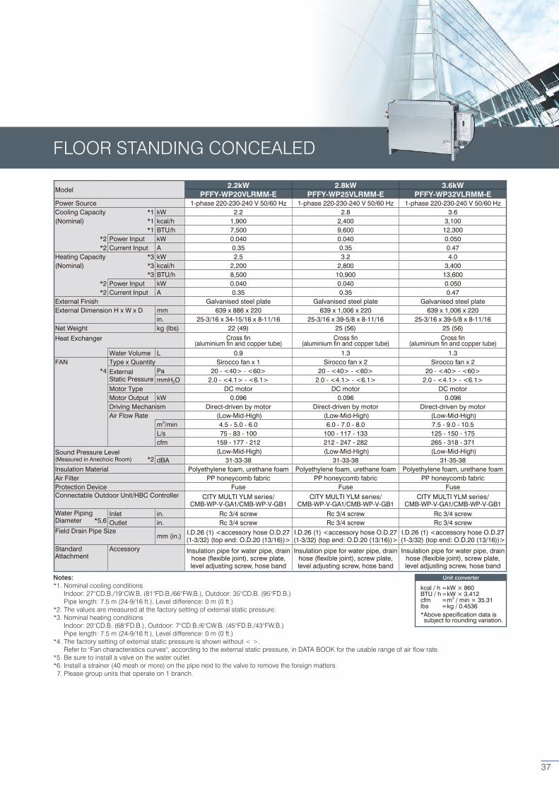
Model 2.2kW 2.8kW 3.6kW
PFFY-WP20VLRMM-E PFFY-WP25VLRMM-E PFFY-WP32VLRMM-EPower Source 1-phase 220-230-240 V 50/60 Hz 1-phase 220-230-240 V 50/60 Hz 1-phase 220-230-240 V 50/60 HzCooling Capacity *1 kW 2.2 2.8 3.6(Nominal) *1 kcal/h 1,900 2,400 3,100
*1 BTU/h 7,500 9,600 12,300*2 Power Input kW 0.040 0.040 0.050*2 Current Input A 0.35 0.35 0.47
Heating Capacity *3 kW 2.5 3.2 4.0(Nominal) *3 kcal/h 2,200 2,800 3,400
*3 BTU/h 8,500 10,900 13,600*2 Power Input kW 0.040 0.040 0.050*2 Current Input A 0.35 0.35 0.47
External Finish Galvanised steel plate Galvanised steel plate Galvanised steel plateExternal Dimension H x W x D mm 639 x 886 x 220 639 x 1,006 x 220 639 x 1,006 x 220
in. 25-3/16 x 34-15/16 x 8-11/16 25-3/16 x 39-5/8 x 8-11/16 25-3/16 x 39-5/8 x 8-11/16Net Weight kg (lbs) 22 (49) 25 (56) 25 (56)
Heat Exchanger Cross fin (aluminium fin and copper tube)
Cross fin (aluminium fin and copper tube)
Cross fin (aluminium fin and copper tube)
Water Volume L 0.9 1.3 1.3FAN Type x Quantity Sirocco fan x 1 Sirocco fan x 2 Sirocco fan x 2
*4 ExternalStatic Pressure
Pa 20 - <40> - <60> 20 - <40> - <60> 20 - <40> - <60>mmH2O 2.0 - <4.1> - <6.1> 2.0 - <4.1> - <6.1> 2.0 - <4.1> - <6.1>
Motor Type DC motor DC motor DC motorMotor Output kW 0.096 0.096 0.096Driving Mechanism Direct-driven by motor Direct-driven by motor Direct-driven by motorAir Flow Rate (Low-Mid-High) (Low-Mid-High) (Low-Mid-High)
m3/min 4.5 - 5.0 - 6.0 6.0 - 7.0 - 8.0 7.5 - 9.0 - 10.5L/s 75 - 83 - 100 100 - 117 - 133 125 - 150 - 175cfm 159 - 177 - 212 212 - 247 - 282 265 - 318 - 371
Sound Pressure Level (Low-Mid-High) (Low-Mid-High) (Low-Mid-High)(Measured in Anechoic Room) *2 dBA 31-33-38 31-33-38 31-35-38Insulation Material Polyethylene foam, urethane foam Polyethylene foam, urethane foam Polyethylene foam, urethane foamAir Filter PP honeycomb fabric PP honeycomb fabric PP honeycomb fabricProtection Device Fuse Fuse FuseConnectable Outdoor Unit/HBC Controller CITY MULTI YLM series/
CMB-WP-V-GA1/CMB-WP-V-GB1CITY MULTI YLM series/
CMB-WP-V-GA1/CMB-WP-V-GB1CITY MULTI YLM series/
CMB-WP-V-GA1/CMB-WP-V-GB1Water PipingDiameter *5,6
Inlet in. Rc 3/4 screw Rc 3/4 screw Rc 3/4 screwOutlet in. Rc 3/4 screw Rc 3/4 screw Rc 3/4 screw
Field Drain Pipe Sizemm (in.) I.D.26 (1) <accessory hose O.D.27
(1-3/32) (top end: O.D.20 (13/16))>I.D.26 (1) <accessory hose O.D.27 (1-3/32) (top end: O.D.20 (13/16))>
I.D.26 (1) <accessory hose O.D.27 (1-3/32) (top end: O.D.20 (13/16))>
Standard Attachment
Accessory Insulation pipe for water pipe, drain hose (flexible joint), screw plate, level adjusting screw, hose band
Insulation pipe for water pipe, drain hose (flexible joint), screw plate, level adjusting screw, hose band
Insulation pipe for water pipe, drain hose (flexible joint), screw plate, level adjusting screw, hose band
Notes:*1. Nominal cooling conditions Indoor: 27°CD.B./19°CW.B. (81°FD.B./66°FW.B.), Outdoor: 35°CD.B. (95°FD.B.) Pipe length: 7.5 m (24-9/16 ft.), Level difference: 0 m (0 ft.)*2. The values are measured at the factory setting of external static pressure.*3. Nominal heating conditions Indoor: 20°CD.B. (68°FD.B.), Outdoor: 7°CD.B./6°CW.B. (45°FD.B./43°FW.B.) Pipe length: 7.5 m (24-9/16 ft.), Level difference: 0 m (0 ft.)*4. The factory setting of external static pressure is shown without < >. Refer to "Fan characteristics curves", according to the external static pressure, in DATA BOOK for the usable range of air flow rate.*5. Be sure to install a valve on the water outlet.*6. Install a strainer (40 mesh or more) on the pipe next to the valve to remove the foreign matters. 7. Please group units that operate on 1 branch.
Unit converter
kcal / h =kW × 860BTU / h =kW × 3,412cfm =m3 / min × 35.31lbs =kg / 0.4536*Above specification data is subject to rounding variation.
FLOOR STANDING CONCEALED
37
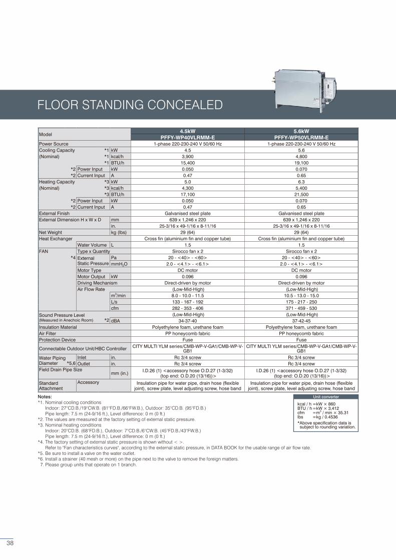
Notes:*1. Nominal cooling conditions Indoor: 27°CD.B./19°CW.B. (81°FD.B./66°FW.B.), Outdoor: 35°CD.B. (95°FD.B.) Pipe length: 7.5 m (24-9/16 ft.), Level difference: 0 m (0 ft.)*2. The values are measured at the factory setting of external static pressure.*3. Nominal heating conditions Indoor: 20°CD.B. (68°FD.B.), Outdoor: 7°CD.B./6°CW.B. (45°FD.B./43°FW.B.) Pipe length: 7.5 m (24-9/16 ft.), Level difference: 0 m (0 ft.)*4. The factory setting of external static pressure is shown without < >. Refer to "Fan characteristics curves", according to the external static pressure, in DATA BOOK for the usable range of air flow rate.*5. Be sure to install a valve on the water outlet.*6. Install a strainer (40 mesh or more) on the pipe next to the valve to remove the foreign matters. 7. Please group units that operate on 1 branch.
Model 4.5kW 5.6kW
PFFY-WP40VLRMM-E PFFY-WP50VLRMM-EPower Source 1-phase 220-230-240 V 50/60 Hz 1-phase 220-230-240 V 50/60 HzCooling Capacity *1 kW 4.5 5.6(Nominal) *1 kcal/h 3,900 4,800
*1 BTU/h 15,400 19,100*2 Power Input kW 0.050 0.070*2 Current Input A 0.47 0.65
Heating Capacity *3 kW 5.0 6.3(Nominal) *3 kcal/h 4,300 5,400
*3 BTU/h 17,100 21,500*2 Power Input kW 0.050 0.070*2 Current Input A 0.47 0.65
External Finish Galvanised steel plate Galvanised steel plateExternal Dimension H x W x D mm 639 x 1,246 x 220 639 x 1,246 x 220
in. 25-3/16 x 49-1/16 x 8-11/16 25-3/16 x 49-1/16 x 8-11/16Net Weight kg (lbs) 29 (64) 29 (64)Heat Exchanger Cross fin (aluminium fin and copper tube) Cross fin (aluminium fin and copper tube)
Water Volume L 1.5 1.5FAN Type x Quantity Sirocco fan x 2 Sirocco fan x 2
*4 ExternalStatic Pressure
Pa 20 - <40> - <60> 20 - <40> - <60>mmH2O 2.0 - <4.1> - <6.1> 2.0 - <4.1> - <6.1>
Motor Type DC motor DC motorMotor Output kW 0.096 0.096Driving Mechanism Direct-driven by motor Direct-driven by motorAir Flow Rate (Low-Mid-High) (Low-Mid-High)
m3/min 8.0 - 10.0 - 11.5 10.5 - 13.0 - 15.0L/s 133 - 167 - 192 175 - 217 - 250cfm 282 - 353 - 406 371 - 459 - 530
Sound Pressure Level (Low-Mid-High) (Low-Mid-High)(Measured in Anechoic Room) *2 dBA 34-37-40 37-42-45Insulation Material Polyethylene foam, urethane foam Polyethylene foam, urethane foamAir Filter PP honeycomb fabric PP honeycomb fabricProtection Device Fuse Fuse
Connectable Outdoor Unit/HBC Controller CITY MULTI YLM series/CMB-WP-V-GA1/CMB-WP-V-GB1
CITY MULTI YLM series/CMB-WP-V-GA1/CMB-WP-V-GB1
Water PipingDiameter *5,6
Inlet in. Rc 3/4 screw Rc 3/4 screwOutlet in. Rc 3/4 screw Rc 3/4 screw
Field Drain Pipe Sizemm (in.) I.D.26 (1) <accessory hose O.D.27 (1-3/32)
(top end: O.D.20 (13/16))>I.D.26 (1) <accessory hose O.D.27 (1-3/32)
(top end: O.D.20 (13/16))>
Standard Attachment
Accessory Insulation pipe for water pipe, drain hose (flexible joint), screw plate, level adjusting screw, hose band
Insulation pipe for water pipe, drain hose (flexible joint), screw plate, level adjusting screw, hose band
FLOOR STANDING CONCEALED
Unit converter
kcal / h =kW × 860BTU / h =kW × 3,412cfm =m3 / min × 35.31lbs =kg / 0.4536*Above specification data is subject to rounding variation.
38
Patented Hybrid VRF Technology
“True flexibility is achieved as the system is modular for a manageable phased installation.”

AN2 for YLM series
AIR CONDITIONING SYSTEMS
MEE15K053
Eco Changes is the Mitsubishi Electric Group’s environmental statement, and expresses the Group’s stance on environmental management. Through a wide range of businesses, we are helping contribute to the realisation of a sustainable society.
The Air Conditioning & Refrigeration Systems Works acquired environmental management system standard ISO 14001 certification.
The ISO 14000 series is a set of standards applying to environmental protection set by the International Standard Organization (ISO). Registered on March 10, 1998.
■
WarningDo not use refrigerant other than the type indicated in the manuals provided with the unit and on the nameplate.- Doing so may cause the unit or pipes to burst, or result in explosion or fire during use, during repair, or at the time of disposal of
the unit.- It may also be in violation of applicable laws.- MITSUBISHI ELECTRIC CORPORATION cannot be held responsible for malfunctions or accidents resulting from the use of the
wrong type of refrigerant.Our air-conditioning equipments and heat pumps contain a fluorinated greenhouse gas, R410A.
■
The Air Conditioning & Refrigeration Systems Works acquired ISO 9001 certification under Series 9000 of the International Standard Organization (ISO) based on a review of Quality management for the production of refrigeration and air conditioning equipment.
ISO Authorization SystemThe ISO 9000 series is a plant authorization system relating to quality management as stipulated by the ISO. ISO 9001 certifies quality management based on the "design, development, production, installation and auxiliary services" for products built at an authorized plant.
FM33568 / ISO 9001;2008
Be sure to ask for Mitsubishi Electric. Other brands share the 3-diamond logo, however are separate to the Mitsubishi Electric brand and cannot supply the
models, features or guarantees outlined in this brochure. | All models, features and specifications are subject to change and amendment at anytime. Oct 2016
AUCKLANDBRANCH
Unit 1, 4 Walls Road
PO Box 12726
Penrose, Auckland 1642
Phone (09) 526 9347
Fax (09) 526 9369
CHRISTCHURCHBRANCH
44 Halwyn Drive
PO Box 16904
Hornby, Christchurch 8441
Phone (03) 341 2837
Fax (03) 341 2838
WELLINGTONHEAD OFFICE
1 Parliament Street
PO Box 30772
Lower Hutt 5040
Phone (04) 560 9147
Fax (04) 560 9133
Black Diamond Technologies
Exclusive distributor of Mitsubishi
Electric products in New Zealand.
www.mitsubishi-electric.co.nz
For more information on Mitsubishi Electric City Multi, please call our customer service team on 0800 784 382
Be sure to ask for Mitsubishi Electric. Other brands share the 3-diamond logo, however they are separate to the Mitsubishi Electric brand and cannot supply the models, features or guarantees outlined in this brochure. | All models, features and specifications are subject to change and amendment at anytime. Feb 2017.
AUCKLANDBRANCH
Unit 1, 4 Walls Road
PO Box 12726
Penrose, Auckland 1642
Phone (09) 526 9347
Fax (09) 526 9369
CHRISTCHURCHBRANCH
44 Halwyn Drive
PO Box 16904
Hornby, Christchurch 8441
Phone (03) 341 2837
Fax (03) 341 2838
WELLINGTONHEAD OFFICE
1 Parliament Street
PO Box 30772
Lower Hutt 5040
Phone (04) 560 9147
Fax (04) 560 9133
Black Diamond Technologies
Exclusive distributor of Mitsubishi
Electric products in New Zealand.
www.mitsubishi-electric.co.nz
For more information on Mitsubishi Electric Heat Pumps, please call our customer service team on 0800 784 382