Embed Size (px)
Citation preview
Hybrid Wireless Mesh Network,Worldwide Satellite Communication,
and PKI Technology for Small SatelliteNetwork System
A project present to The Faculty of the Department of Aerospace Engineering
San Jose State University
in partial fulfillment of the requirements for the degree Master of Science in Aerospace Engineering
By
Stephen S. Im
May 2015
approved by
Dr. Periklis Papadopoulos Faculty Advisor
1

©2015Stephen S. Im
ALL RIGHTS RESERVED
2
An Abstract of
Hybrid Wireless Mesh Network, Worldwide Satellite Communication, and PKI Technology for
Small Satellite Network System
by
Stephen S. Im1
San Jose State UniversityMay 2015
Small satellites are getting the spotlight in the aerospace industry because this earth-
orbiting technology is well-suited for use in military service, space mission research, weather
prediction, wireless communication, scientific observation, and education demonstration. Small
satellites have advantages of low cost of manufacturing, ease of mass production, low cost of
launch system, ability to be launched in groups, and minimal financial failure. Until now, a
number of the small satellites have been built and launched for various purposes. As network
simplification, operation efficiency, communication accessibility, and high-end data security are
the fundamental communication factors for small satellite operations, a standardized space
network communication with strong data protection has become a significant technology. This is
also highly beneficial for mass manufacture, compatible for cross-platform, and common error
detection. And the ground-based network technologies which fulfill Internet-of-Things (IOT)
concept, which consist of Wireless Mesh Network (WMN) and data security, are presented in
this paper.
1Graduate Student, San Jose State University, One Washington Square, San Jose, CA.4

Acknowledgments
I would like to express my special gratitude to my committee members, Professor
Mourtos, Professor Papadopoulos, and Professor Murbach. You all have been tremendous
mentors for me. I really appreciate for encouraging my project and providing me aerospace
knowledge. I would also like to thank my old collegue, Greenfield Trinh and MRMSS team.
Greenfield introduced me to MPACE and Modular Rapidly Manufactured Small Satellite
(MRMSS), and has worked together for many projects. And Kenneth Cheung, the project
manager for MRMSS and Daniel Cellucci, have been there to support me with great advices
and necessary equipment.
Special thanks to my family and friends. Words cannot express how grateful I am to my
father, mother, sister, brother-in law, nephew, niece, my wife’s brother, father-in-law, mother-in-
law for all the prayer whom you’ve made on my behalf. I would also like to thank all of my best
friends who supported me with prayers. There is one more person. I would like express
appreciation to my beloved wife, Elizabeth Shin, who is always my support in every moment and
every event.
5
Table of Contents
Abstract........................................................................................................................................................................4
Acknowledgments....................................................................................................................................................5
Table of Contents......................................................................................................................................................6
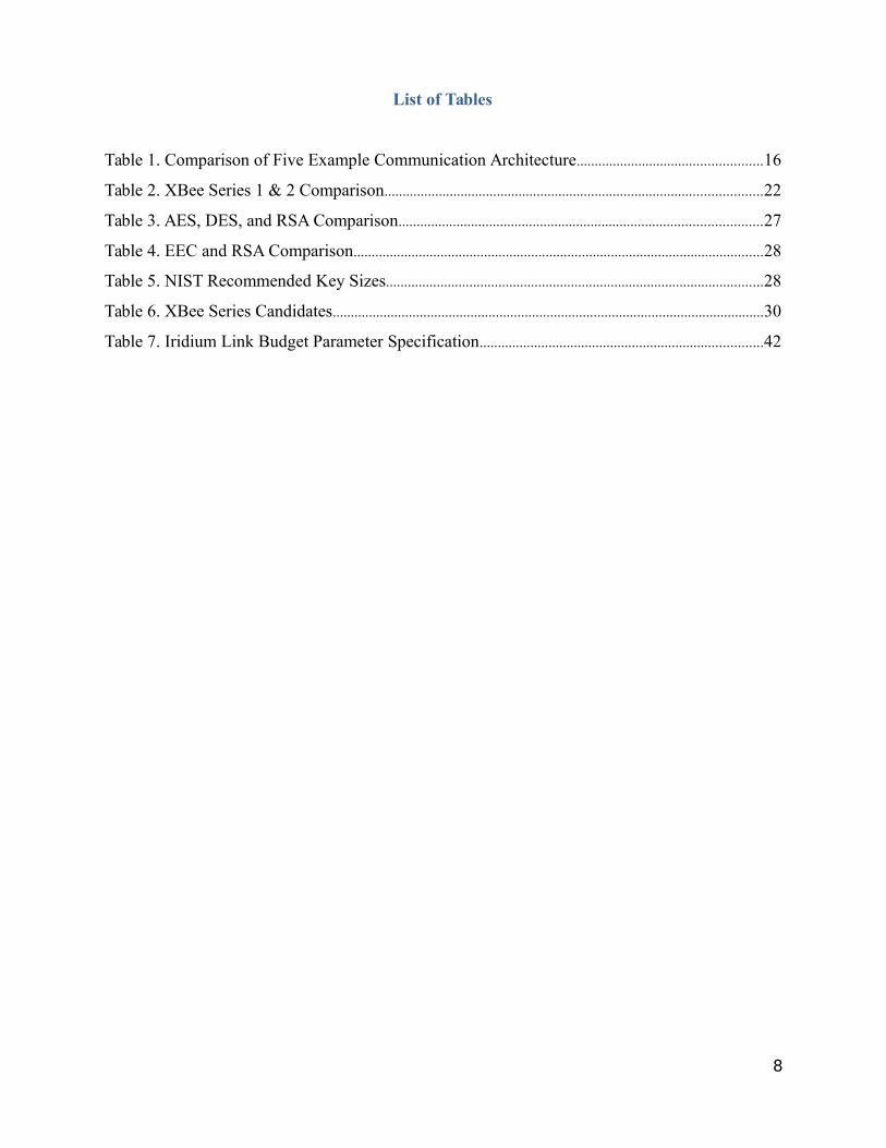
List of Tables..............................................................................................................................................................8
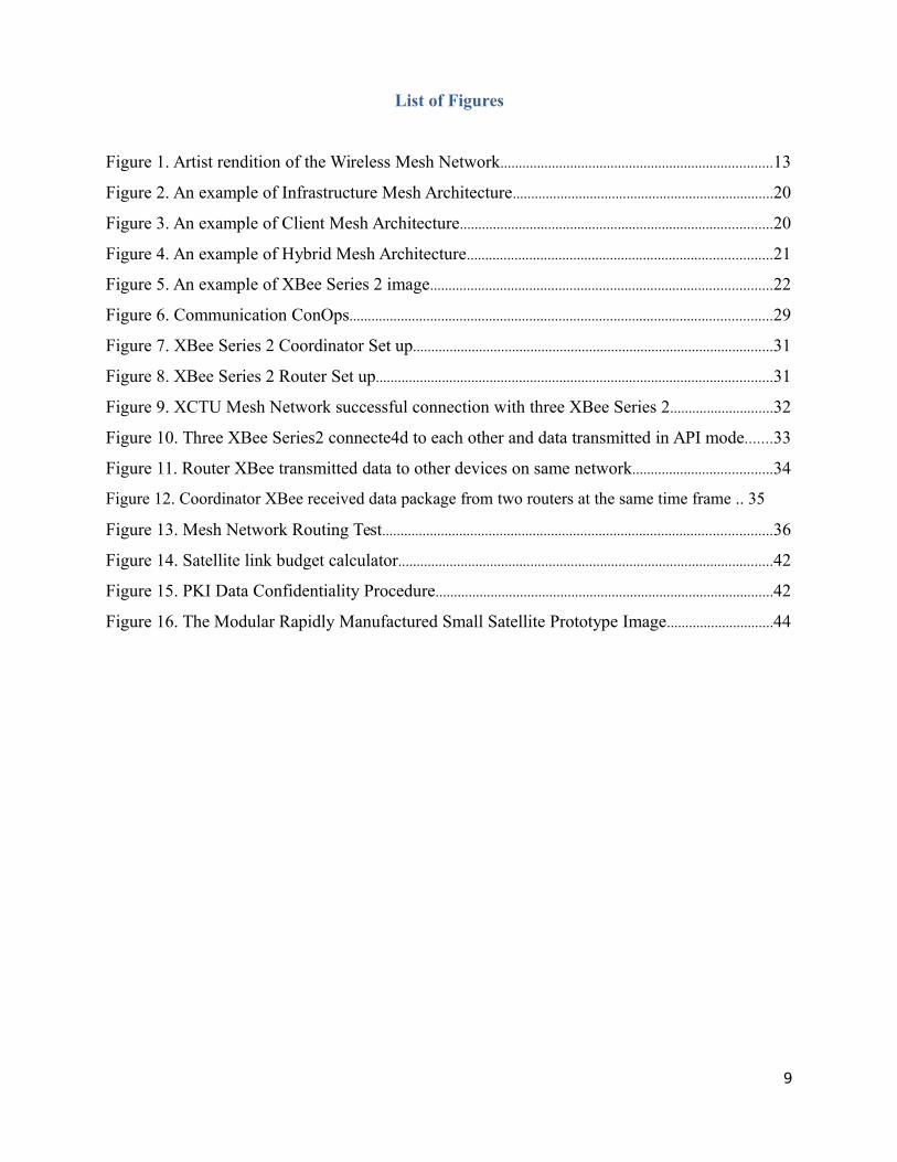
List of Figures............................................................................................................................................................9
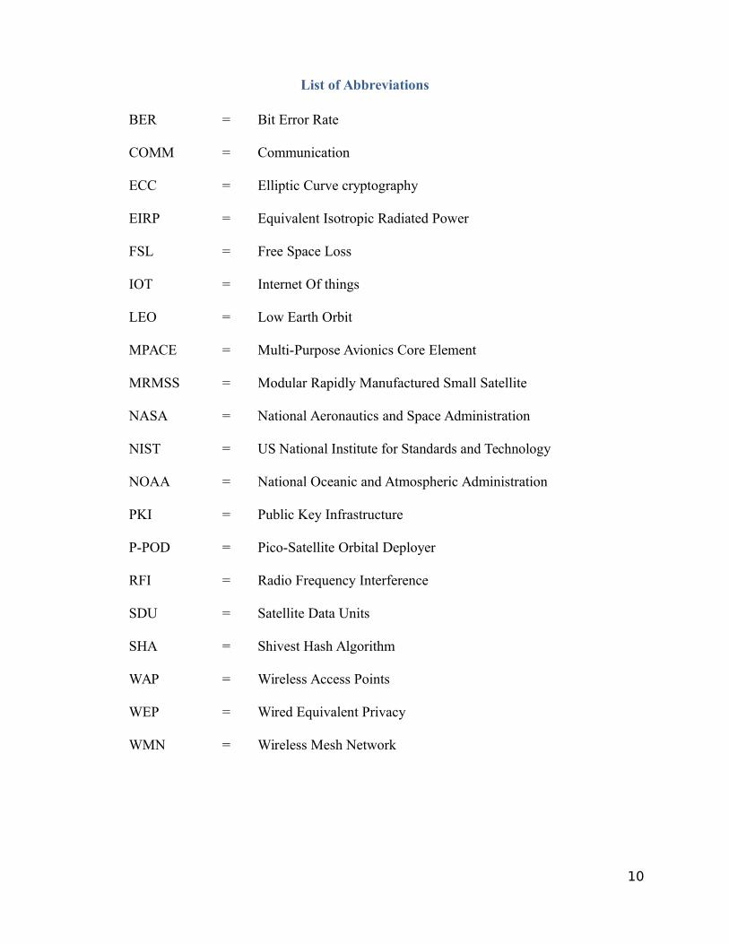
List of Abbreviations.............................................................................................................................................10
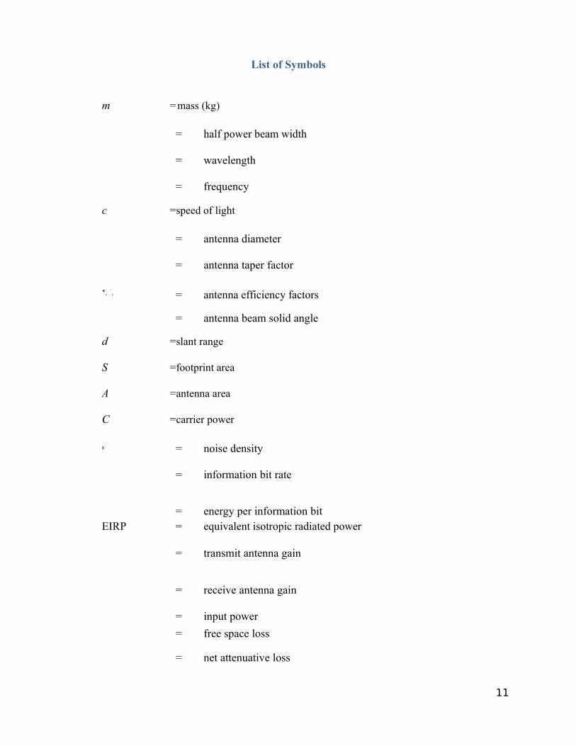
List of Symbols.......................................................................................................................................................11
I. Introduction..........................................................................................................................................................13
A. Motivation......................................................................................................................................................14
B. Objectives.......................................................................................................................................................14
II. Literature Review.............................................................................................................................................14
A. Brief History of Small Satellites.............................................................................................................14
B. Communication Architecture....................................................................................................................15
C. Wireless Mesh Network.............................................................................................................................17
1. Wireless Network Topologies...............................................................................................................17
1.1 Infrastructure Network Topology..................................................................................................18
1.2 Ad-Hoc Network Topology............................................................................................................18
1.3 Advantages and Disadvantages of Wireless Network Topologies......................................18
2. Wireless Mesh Network (WMN).........................................................................................................19
2.1 Infrastructure Mesh Architecture..................................................................................................19
2.2 Client Mesh Architecture.................................................................................................................20
2.3 Hybrid Mesh Architecture...............................................................................................................21
D. XBee Radio Module..................................................................................................................................22
1. Series 1 vs Series 2...................................................................................................................................23
2. Radio Frequency Interference...............................................................................................................24
E. Internet of Things (IoT)..............................................................................................................................25
F. Satellite Constellation..................................................................................................................................25
1. LEO Satellite Constellation Service...................................................................................................24
1.1 Iridium...................................................................................................................................................24
1.2 IsatPhone..............................................................................................................................................25
1.3 Globalstar.............................................................................................................................................25
6
G. Data Security and Encryption Algorithms............................................................................................27
1. Data vulnerability issue..........................................................................................................................27
2. Available Key Encryption Algorithms...............................................................................................28
III. Technology Development.............................................................................................................................30
A. Communication Architecture...................................................................................................................31
B. Hybrid WMN with XBee devices...........................................................................................................31
1. Overview.....................................................................................................................................................31
2. XBee Series 2 for Level-1 Communication.....................................................................................32
2.1 XBee Module Coordinator and Router Settings.......................................................................32
2.2 Arduino Programming Codes for Coordinator and Routers.................................................35
2.3 Mesh Network Routing Test...........................................................................................................37
3. XTend 900 for Level-2 Communication...........................................................................................39
C. Iridium Link Budget....................................................................................................................................39
D. PKI technology.............................................................................................................................................44
1. PKI Methodology.....................................................................................................................................44
2. Encryption / Decryption data - RSA cryptography........................................................................45
IV. Discussion and Future Work........................................................................................................................47
V. Conclusion..........................................................................................................................................................48
VI. References.........................................................................................................................................................49
VII.Appendices.......................................................................................................................................................51
Appendix A: Arduino codes for XBee Series 2 – Coordinator................................................................51
Appendix B: Arduino codes for XBee Series 2 - routers...........................................................................56
Appendix C: Encryption / Decryption Sample code in Arduino.............................................................61
Appendix D: XBee Coordinator setting for XCTU.....................................................................................63
Appendix E: XBee Router setting for XCTU................................................................................................64
7
List of Tables
Table 1. Comparison of Five Example Communication Architecture...................................................16
Table 2. XBee Series 1 & 2 Comparison........................................................................................................22
Table 3. AES, DES, and RSA Comparison....................................................................................................27
Table 4. EEC and RSA Comparison.................................................................................................................28
Table 5. NIST Recommended Key Sizes........................................................................................................28
Table 6. XBee Series Candidates.......................................................................................................................30
Table 7. Iridium Link Budget Parameter Specification..............................................................................42
8
List of Figures
Figure 1. Artist rendition of the Wireless Mesh Network..........................................................................13
Figure 2. An example of Infrastructure Mesh Architecture.......................................................................20
Figure 3. An example of Client Mesh Architecture.....................................................................................20
Figure 4. An example of Hybrid Mesh Architecture...................................................................................21
Figure 5. An example of XBee Series 2 image.............................................................................................22
Figure 6. Communication ConOps...................................................................................................................29
Figure 7. XBee Series 2 Coordinator Set up..................................................................................................31
Figure 8. XBee Series 2 Router Set up............................................................................................................31
Figure 9. XCTU Mesh Network successful connection with three XBee Series 2............................32
Figure 10. Three XBee Series2 connecte4d to each other and data transmitted in API mode.......33
Figure 11. Router XBee transmitted data to other devices on same network......................................34
Figure 12. Coordinator XBee received data package from two routers at the same time frame .. 35
Figure 13. Mesh Network Routing Test..........................................................................................................36
Figure 14. Satellite link budget calculator......................................................................................................42
Figure 15. PKI Data Confidentiality Procedure............................................................................................42
Figure 16. The Modular Rapidly Manufactured Small Satellite Prototype Image.............................44
9
List of Abbreviations
BER = Bit Error Rate
COMM = Communication
ECC = Elliptic Curve cryptography
EIRP = Equivalent Isotropic Radiated Power
FSL = Free Space Loss
IOT = Internet Of things
LEO = Low Earth Orbit
MPACE = Multi-Purpose Avionics Core Element
MRMSS = Modular Rapidly Manufactured Small Satellite
NASA = National Aeronautics and Space Administration
NIST = US National Institute for Standards and Technology
NOAA = National Oceanic and Atmospheric Administration
PKI = Public Key Infrastructure
P-POD = Pico-Satellite Orbital Deployer
RFI = Radio Frequency Interference
SDU = Satellite Data Units
SHA = Shivest Hash Algorithm
WAP = Wireless Access Points
WEP = Wired Equivalent Privacy
WMN = Wireless Mesh Network
10
List of Symbols
m =mass (kg)
= half power beam width
= wavelength
= frequency
c =speed of light
= antenna diameter
= antenna taper factor
∗, ′, = antenna efficiency factors
= antenna beam solid angle
d =slant range
S =footprint area
A =antenna area
C =carrier power
0 = noise density
= information bit rate
= energy per information bitEIRP = equivalent isotropic radiated power
= transmit antenna gain
= receive antenna gain
= input power
= free space loss
= net attenuative loss
11

T =system noise temperature
= Boltzmann’s constant
12
I. Introduction
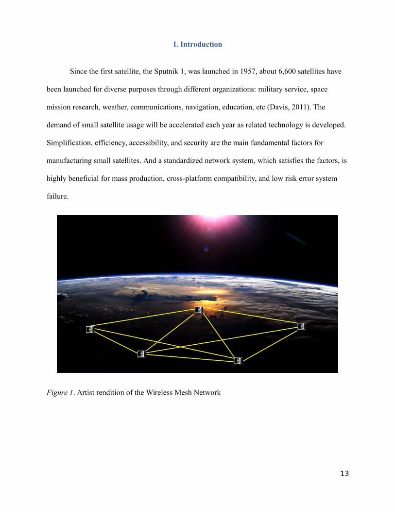
Since the first satellite, the Sputnik 1, was launched in 1957, about 6,600 satellites have
been launched for diverse purposes through different organizations: military service, space
mission research, weather, communications, navigation, education, etc (Davis, 2011). The
demand of small satellite usage will be accelerated each year as related technology is developed.
Simplification, efficiency, accessibility, and security are the main fundamental factors for
manufacturing small satellites. And a standardized network system, which satisfies the factors, is
highly beneficial for mass production, cross-platform compatibility, and low risk error system
failure.
Figure 1. Artist rendition of the Wireless Mesh Network
13
A. Motivation
During my NASA volunteer projects, Multi-Purpose Avionics Core Element (M-PACE)
and Modular Rapidly Manufactured Small Satellite (MRMSS), I was able to see many
successful small satellite projects. However, we still have technical deficiencies for an advanced
network communication, for instance, data transmission speed, avionic space usage, cross-over
operations among components, data security, etc. Today, there are a number of ground-based
technologies in network and security fields that can provide a great solution for the deficiencies.
And such technology will contribute to the development of space mission projects in near future.
B. Objectives
The objectives of this project are as follows:
1. To research for ground-based wireless network architecture
2. To implement hybrid WMN with XBee series devices on cube satellite prototypes
- Cooperated with the Modular Rapidly Manufactured Small Satellite (MRMSS)
team, which implemented wireless communication with XBee Series 1
3. To deploy Public-key Infrastructure (PKI) for securing the satellite date
II. Literature Review
A. Brief summary of small satellites
Miniaturized satellite industry has been growing rapidly in recent years. Research by
Cockrell (2012) states that miniaturized satellites are usually deployed in low earth orbits (LEO)
and are grouped on launch and placed in elliptical orbits. This is called “swarms.” And small
14
satellites can be classified according to mass. Microsatellite (or Microsat) masses are between 10
kg and 500 kg, a weight range of 22 pounds (lb) to 1100 lb. Nanosatellite (or Nanosat) masses
are between 1 kg and 10 kg (2.2 lb and 22 lb). Picosatellite (or Picosat) masses are less than 1 kg
(2.2 lb).
Advantages of Miniaturized satellites:
• Lower cost of manufacture
• Ease of mass production
• Lower cost of launch
• Ability to be launched in groups or "piggyback" along with larger satellites
• Minimal financial loss in case of failure
Disadvantages of Miniaturized satellites compared to larger size satellites:
• Generally shorter working life
• Reduced hardware-carrying capacity
• Lower transmitter output power capability
B. Communication architecture
Communication architecture is a network of satellites and ground points on earth that are
interconnected by communication links. Communication links enable to carry tracking, telemetry,
and command or mission data among satellites. Larson (2005) explains that the world’s first
artificial communication satellite, which is capable of relaying signals to points on earth, was
15
‘Echo-1’. It was a metallic balloon and inflatable satellite. In 1958, project SCORE used the first
tape recorder to store and forward voice message to ground station (Larson, 2005).
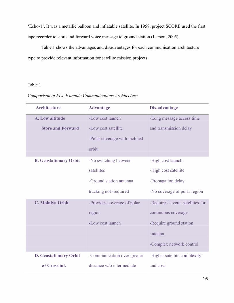
Table 1 shows the advantages and disadvantages for each communication architecture
type to provide relevant information for satellite mission projects.
Table 1
Comparison of Five Example Communications Architecture
Architecture Advantage Dis-advantage
A. Low altitude -Low cost launch -Long message access time
Store and Forward -Low cost satellite and transmission delay
-Polar coverage with inclined
orbit
B. Geostationary Orbit -No switching between -High cost launch
satellites -High cost satellite
-Ground station antenna -Propagation delay
tracking not -required -No coverage of polar region
C. Molniya Orbit -Provides coverage of polar -Requires several satellites for
region continuous coverage
-Low cost launch -Require ground station
antenna
-Complex network control
D. Geostationary Orbit -Communication over greater -Higher satellite complexity
w/ Crosslink distance w/o intermediate and cost
16
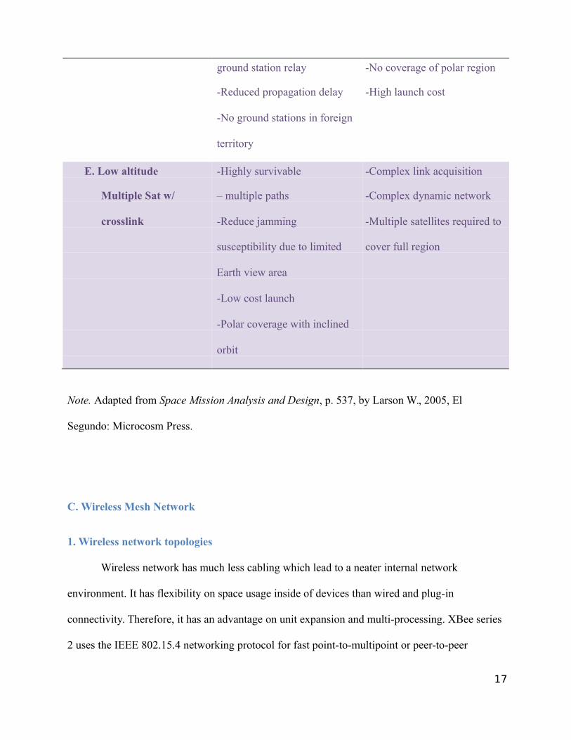
ground station relay -No coverage of polar region
-Reduced propagation delay -High launch cost
-No ground stations in foreign
territory
E. Low altitude -Highly survivable -Complex link acquisition
Multiple Sat w/ – multiple paths -Complex dynamic network
crosslink -Reduce jamming -Multiple satellites required to
susceptibility due to limited cover full region
Earth view area
-Low cost launch
-Polar coverage with inclined
orbit
Note. Adapted from Space Mission Analysis and Design, p. 537, by Larson W., 2005, El
Segundo: Microcosm Press.
C. Wireless Mesh Network
1. Wireless network topologies
Wireless network has much less cabling which lead to a neater internal network
environment. It has flexibility on space usage inside of devices than wired and plug-in
connectivity. Therefore, it has an advantage on unit expansion and multi-processing. XBee series
2 uses the IEEE 802.15.4 networking protocol for fast point-to-multipoint or peer-to-peer
17
networking and performs to transmit data from one to another processing unit (Ahmed, 2012).
Furthermore, XBee series 2 supports MESH topology, which has redundancy factor and avoids
high traffic (Ahmed, 2012). In the network, all participating computers potentially
communicate with each other directly. Akyildiz and Wang’s (2004) research paper states that
Wireless has only two topologies: infrastructure and ad hoc. This is a direct and natural result of
the non-physical nature of interaction of computers in a wireless network.
1.1 Infrastructure Network Topology
Infrastructure wireless network topology is a hub and spoke topology, also known as a
point to multipoint or one to many topologies. In the infrastructure topology, there is a single
central wireless access point (WAP). It acts as the hub in the network, with all the other
computers (or spokes) connecting to it (Akyildiz & Wang, 2004).
1.2 Ad Hoc Network Topology
Ad hoc wireless network topology is multipoint to multipoint topology. There is no
central access point in an ad-hoc network structure; every computer on the network
communicates directly with every other on the network. So, ad hoc wireless network
topologies are essentially mesh networks (Akyildiz & Wang, 2004).
1.3 Advantages and Disadvantages of Wireless Network Topologies
This ad-hoc topology has an advantage of not requiring a central access point or WAP.
However, this also means only a few security modes and much lower network speeds are
18
available on such topology. And Akyildiz and Wang (2004) states wired equivalent privacy
(WEP) and a maximum speed of 11 megabits per second are implemented on ad-hoc networks.
On the other hand, Infrastructure topology has an advantage of higher speeds and stronger
security to such network, but it requires the extra equipment of a central WAP.
Wireless networks fall into only two types of network topologies: infrastructure and ad
hoc. Each of these typologies has its own advantages and disadvantages and is suitable for
different usage situations. The infrastructure topology is typically used for permanent networks,
while the ad-hoc topology is used for temporary networks (Akyildiz & Wang, 2004).
2. Wireless Mesh Network (WMN)
Wireless mesh network (WMN) is a network created through the connection of wireless
access points installed at each network user's locale. Each network user is also a provider,
forwarding data to the next node. This networking infrastructure is decentralized and simplified
because each node only needs to transmit as far as the next node (Akyildiz & Wang, 2004).
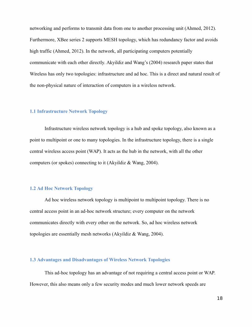
2.1 Infrastructure Mesh Architecture
In infrastructure mesh architecture, mesh routers collectively provide a wireless backbone
infrastructure. Client nodes are passive in mesh infrastructure. Via Ethernet links, conventional
clients with Ethernet interfaces can be connected to mesh routers (Akyildiz & Wang, 2004).
19
Figure 2. An example of Infrastructure Mesh Architecture. Adapted from Wireless mesh
networks: a survey (p. 448), by I. Akyildiz, X. Wang, 2004, Bridgewater, NJ: Elsevier B.V.
Copyright 2004 by Elsevier B.V.
2.2 Client Mesh Architecture
The client mesh architecture provides peer-to-peer networks among client devices. Here,
no such mesh router is required. Clients will act like mesh routers by relaying the packets
(Akyildiz & Wang, 2004).
20
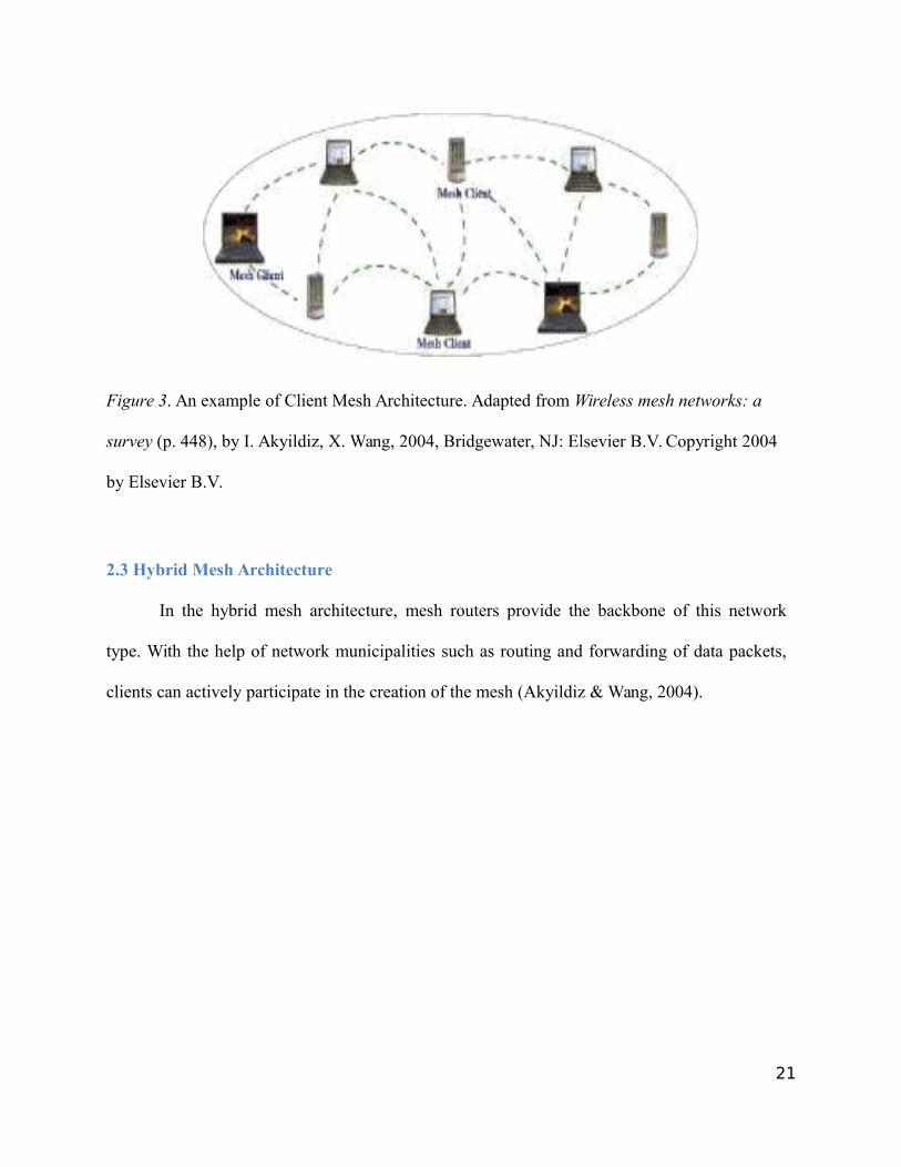
Figure 3. An example of Client Mesh Architecture. Adapted from Wireless mesh networks: a
survey (p. 448), by I. Akyildiz, X. Wang, 2004, Bridgewater, NJ: Elsevier B.V. Copyright 2004
by Elsevier B.V.
2.3 Hybrid Mesh Architecture
In the hybrid mesh architecture, mesh routers provide the backbone of this network
type. With the help of network municipalities such as routing and forwarding of data packets,
clients can actively participate in the creation of the mesh (Akyildiz & Wang, 2004).
21
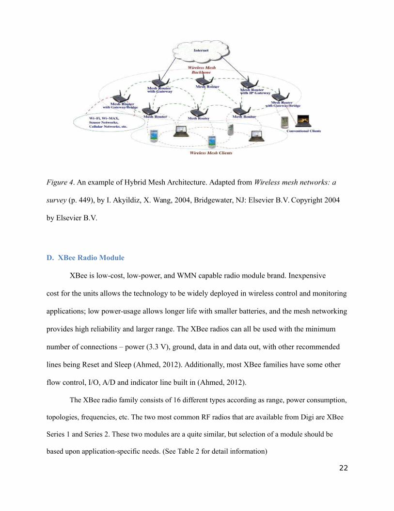
Figure 4. An example of Hybrid Mesh Architecture. Adapted from Wireless mesh networks: a
survey (p. 449), by I. Akyildiz, X. Wang, 2004, Bridgewater, NJ: Elsevier B.V. Copyright 2004
by Elsevier B.V.
D. XBee Radio Module
XBee is low-cost, low-power, and WMN capable radio module brand. Inexpensive
cost for the units allows the technology to be widely deployed in wireless control and monitoring
applications; low power-usage allows longer life with smaller batteries, and the mesh networking
provides high reliability and larger range. The XBee radios can all be used with the minimum
number of connections – power (3.3 V), ground, data in and data out, with other recommended
lines being Reset and Sleep (Ahmed, 2012). Additionally, most XBee families have some other
flow control, I/O, A/D and indicator line built in (Ahmed, 2012).
The XBee radio family consists of 16 different types according as range, power consumption,
topologies, frequencies, etc. The two most common RF radios that are available from Digi are XBee
Series 1 and Series 2. These two modules are a quite similar, but selection of a module should be
based upon application-specific needs. (See Table 2 for detail information)
22
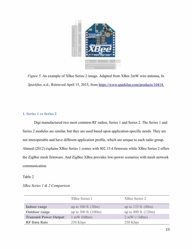
Figure 5. An example of XBee Series 2 image. Adapted from XBee 2mW wire antenna, In
Sparkfun, n.d., Retrieved April 15, 2015, from https://www.sparkfun.com/products/10414.
1. Series 1 vs Series 2
Digi manufactured two most common RF radios, Series 1 and Series 2. The Series 1 and
Series 2 modules are similar, but they are used based upon application-specific needs. They are
not interoperable and have different application profile, which are unique to each radio group.
Ahmed (2012) explains XBee Series 1 comes with 802.15.4 firmware while XBee Series 2 offers
the ZigBee mesh firmware. And ZigBee XBee provides low-power scenarios with mesh network
communication.
Table 2
XBee Series 1 & 2 Comparison
XBee Series 1 XBee Series 2
Indoor range up to 100 ft. (30m) up to 133 ft. (40m)Outdoor range up to 300 ft. (100m) up to 400 ft. (120m)Transmit Power Output 1 mW (0dbm) 2 mW (+3dbm)RF Data Rate 250 Kbps 250 Kbps
23
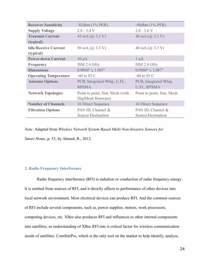
Receiver Sensitivity -92dbm (1% PER) -98dbm (1% PER)Supply Voltage 2.8 - 3.4 V 2.8 - 3.6 VTransmit Current 45 mA (@ 3.3 V) 40 mA (@ 3.3 V)(typical)
Idle/Receive Current 50 mA (@ 3.3 V) 40 mA (@ 3.3 V)(typical)Power-down Current 10 uA 1 uAFrequency ISM 2.4 GHz ISM 2.4 GHzDimensions 0.0960" x 1.087" 0.0960" x 1.087"Operating Temperature -40 to 85 C -40 to 85 CAntenna Options PCB, Integrated Whip, U.FL, PCB, Integrated Whip,
RPSMA U.FL, RPSMA
Network Topologies Point to point, Star, Mesh (with Point to point, Star, MeshDigiMesh firmware)
Number of Channels 16 Direct Sequence 16 Direct Sequence
Filtration Options PAN ID, Channel & PAN ID, Channel &Source/Destination Source/Destination
Note. Adapted from Wireless Network System Based Multi-Non-Invasive Sensors for
Smart Home, p. 53, by Ahmed, R., 2012.
2. Radio Frequency Interference
Radio frequency interference (RFI) is radiation or conduction of radio frequency energy.
It is emitted from sources of RFI, and it directly affects to performance of other devices into
local network environment. Most electrical devices can produce RFI. And the common sources
of RFI include several components, such as, power supplies, motors, work processors,
computing devices, etc. XBee also produces RFI and influences to other internal components
into satellites, so understanding of XBee RFI rate is critical factor for wireless communication
inside of satellites. ComSitePro, which is the only tool on the market to help identify, analyze,
24
locate and resolve RFI, will be used in this project to measure RFI rate of XBee modules. It is
capable to calculate accurate values of RFI rate by analyzing transmitter noise, receiver
desensitization, transmitter and receiver produced intermodulation products, harmonics, and
spurious output (“ComSite Pro Wireless”, 2014).
E. Internet of Things (IoT)
The Internet of Things (IoT) is a network of physical objects connected over the internet.
When objects can detect or measure current conditions through sensors and communicate to each
other, then they are able to identify themselves to other devices.
In IoT, a thing can be a person with a heart monitor implant, a farm animal with a biochip
transponder, an automobile that has built-in sensors to alert the driver when tire pressure is low
(Kevin, 2009). Any other natural or human-made object that has an assigned IP address and an
ability to transfer data over a network is a thing. So far, the Internet of Things has been most
closely associated with machine-to-machine (M2M) communication in manufactures and powers
by oil and gas utilities. Products with M2M communication capabilities are often referred to as
being smart (Kevin, 2009).
G. Satellite Constellation
1. LEO Satellite Constellation Services
LEO satellite constellation is a group of satellites in Low-Earth Orbit, cooperating
together to provide multiple communication services to the ground. There are three major
satellite communications in the low-earth low (LEO): Globalstar, Iridium and the IsatPhone. All
25
three have different communication network environments, and each has advantages and
disadvantages.
1.1 Iridium
Alan G. (2012) described that iridium satellite service is the only satellite phone
provider which provides worldwide coverage, including all the oceans and Polar Regions. The
Iridium satellite constellation is made of 66 Low Earth Orbiting (LEO) satellites that include
the polar orbit. This has polar orbits at an altitude of 485 miles and orbits from pole-to-pole
gathering close together as they approach the Polar Regions.
1.2 IsatPhone
Alan G. (2012) described that IsatPhone satellite provides worldwide coverage excluding
only the Polar Regions. The IsatPhone uses Inmarsat's three I4 satellites covering a majority of
the earth. Some areas, including Northern Alaska, Greenland, and Northern Russian, may have
limited access or no coverage. It would be these areas where the Iridium phone would give the
only coverage available with a satellite phone. They are in a geostationary orbit 37,786 km
(22,240 miles) above the Earth and beam their signals down to earth like numerous super
flashlights.
1.3 Globalstar
Alan G. (2012) described that Globalstar satellite service provides global regional
coverage in over 100 countries throughout the world. The Globalstar satellite constellation is
made of 32 Low Earth Orbiting (LEO) satellites which are 876 miles from the earth. Globalstar
26
uses "bent-pipe" technology that transmits telecommunications from one location on Earth to a
satellite location, and then again down to another location on Earth. A call comes from a
Globalstar phone is routed via CDMA technology to a satellite dish or ground station, and then
the call is routed locally through the terrestrial telecommunications system.
G. Data Security and Encryption Algorithms
In these years, network security has become a significant topic. According to “The case of
Elliptic” (2009), network security can provide many business benefits: Data's protection from
business disruption, qualifying regulatory compliance, reducing the risk of legal action from theft,
and business reputation. There are several techniques to protect the shared data which focus on
cryptography to secure the data while transmitting on the network protocols.
1. Data vulnerability issue
As satellite technology has improved in worldwide states, the issue of communication
security is a top priority. In conventional satellite communication up and downlinks, a satellite
implements an antenna to receive and transmit commands and data. A concern involved
throughout this transaction process is a misuse of the communication and intercepting
information.
In October 2014, Ruben Santamarta who is a principal security consultant at
IOActive Security Services, spoke about satellite communication systems vulnerability issue
during the Black Hat USA conference. Santamarta published a paper that states security
vulnerabilities issues on the systems made by Cobham and Iridium, and he even shows how
they can get an access satellite data units (Matt, 2014).
And satellite network vulnerability issue actually occurred last year in the U.S.A. The
27
National Oceanic and Atmospheric Administration (NOAA)’s Satellite Data and Information
service network was hacked in September, 2014. It caused a disruption in satellite feeds and
several pivotal websites. To block the attacker, government was forced to shut down some of its
services, and it explains why satellite data was cut off in October 2014 (Thurber, 2014; Werner,
2012).
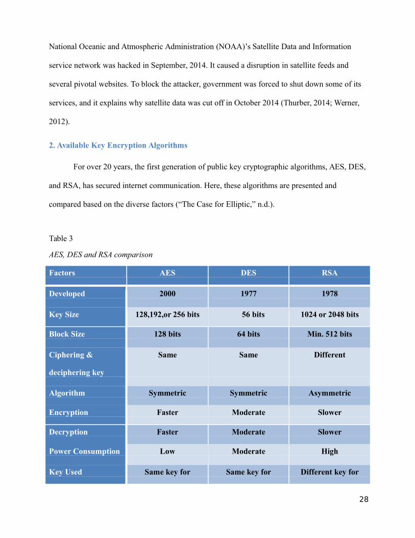
2. Available Key Encryption Algorithms
For over 20 years, the first generation of public key cryptographic algorithms, AES, DES,
and RSA, has secured internet communication. Here, these algorithms are presented and
compared based on the diverse factors (“The Case for Elliptic,” n.d.).
Table 3
AES, DES and RSA comparison
Factors AES DES RSA
Developed 2000 1977 1978
Key Size 128,192,or 256 bits 56 bits 1024 or 2048 bits
Block Size 128 bits 64 bits Min. 512 bits
Ciphering & Same Same Different
deciphering key
Algorithm Symmetric Symmetric Asymmetric
Encryption Faster Moderate Slower
Decryption Faster Moderate Slower
Power Consumption Low Moderate High
Key Used Same key for Same key for Different key for
28
Encrypt and Decrypt Encrypt and Decrypt Encrypt and Decrypt
Note. Adapted from The Case for Elliptic Curve Cryptography, byace Mission Analysis and
Design, 2009, Retrieved from https://www.nsa.gov/business/programs/elliptic_curve.shtml
The majority of public key systems in use today apply 1024-bit parameters for RSA, but
the US National Institute for Standards and Technology (NIST) has recommended that 1024-bit
systems are only sufficient until 2010. The first option to follow the recommendation is simply to
increase the public key size, and the other option is to move away from the first generation key
algorithm to the elliptical curve cryptography (“The Case for Elliptic,” n.d.).
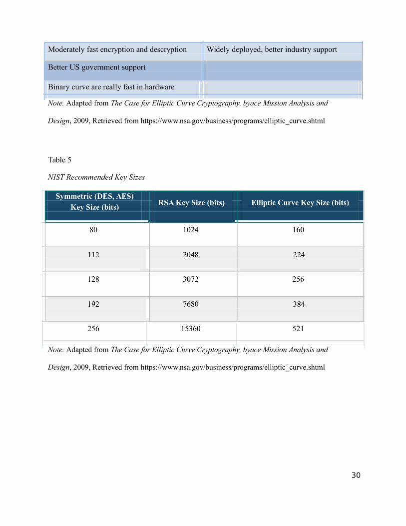
ECC is a public key encryption technique based on elliptic curve theory. The main
advantage of ECC in comparison with non-ECC cryptography is that the same level of security
provided by keys of smaller size. Table 5 is the list of NIST recommended key sizes for
symmetric, RSA, ECC cryptographies. ECC provides greater security, more efficient
performance, and better US government support than the first generation public key algorithms
now in use (“The Case for Elliptic,” n.d.).
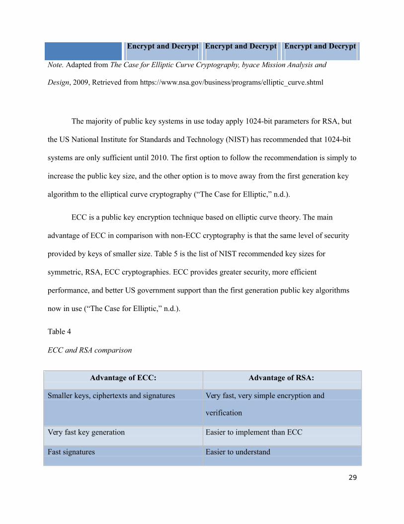
Table 4
ECC and RSA comparison
Advantage of ECC: Advantage of RSA:
Smaller keys, ciphertexts and signatures Very fast, very simple encryption and
verification
Very fast key generation Easier to implement than ECC
Fast signatures Easier to understand
29
Moderately fast encryption and descryption Widely deployed, better industry support
Better US government support
Binary curve are really fast in hardware
Note. Adapted from The Case for Elliptic Curve Cryptography, byace Mission Analysis and
Design, 2009, Retrieved from https://www.nsa.gov/business/programs/elliptic_curve.shtml
Table 5
NIST Recommended Key Sizes
Symmetric (DES, AES)RSA Key Size (bits) Elliptic Curve Key Size (bits)
Key Size (bits)
80 1024 160
112 2048 224
128 3072 256
192 7680 384
256 15360 521
Note. Adapted from The Case for Elliptic Curve Cryptography, byace Mission Analysis and
Design, 2009, Retrieved from https://www.nsa.gov/business/programs/elliptic_curve.shtml
30
IV. Technology Development
A. Communication Architecture
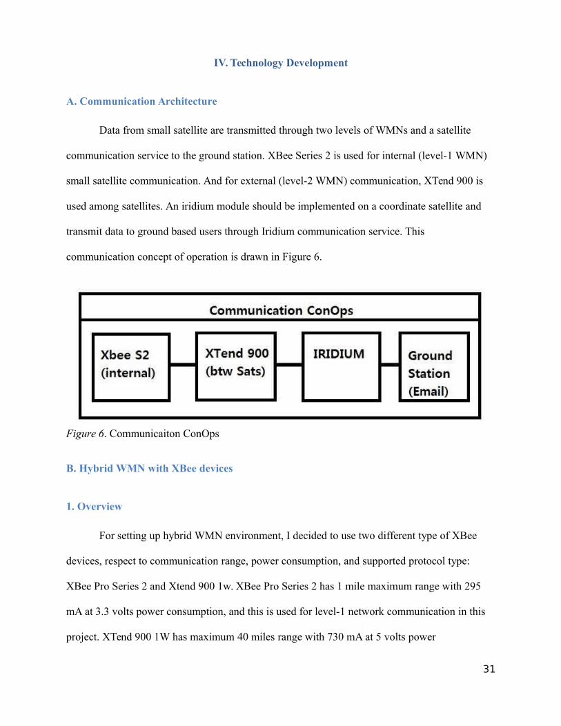
Data from small satellite are transmitted through two levels of WMNs and a satellite
communication service to the ground station. XBee Series 2 is used for internal (level-1 WMN)
small satellite communication. And for external (level-2 WMN) communication, XTend 900 is
used among satellites. An iridium module should be implemented on a coordinate satellite and
transmit data to ground based users through Iridium communication service. This
communication concept of operation is drawn in Figure 6.
Figure 6. Communicaiton ConOps
B. Hybrid WMN with XBee devices
1. Overview
For setting up hybrid WMN environment, I decided to use two different type of XBee
devices, respect to communication range, power consumption, and supported protocol type:
XBee Pro Series 2 and Xtend 900 1w. XBee Pro Series 2 has 1 mile maximum range with 295
mA at 3.3 volts power consumption, and this is used for level-1 network communication in this
project. XTend 900 1W has maximum 40 miles range with 730 mA at 5 volts power
31
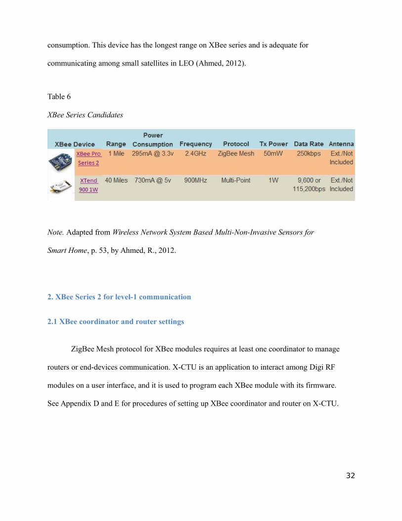
consumption. This device has the longest range on XBee series and is adequate for
communicating among small satellites in LEO (Ahmed, 2012).
Table 6
XBee Series Candidates
Note. Adapted from Wireless Network System Based Multi-Non-Invasive Sensors for
Smart Home, p. 53, by Ahmed, R., 2012.
2. XBee Series 2 for level-1 communication
2.1 XBee coordinator and router settings
ZigBee Mesh protocol for XBee modules requires at least one coordinator to manage
routers or end-devices communication. X-CTU is an application to interact among Digi RF
modules on a user interface, and it is used to program each XBee module with its firmware.
See Appendix D and E for procedures of setting up XBee coordinator and router on X-CTU.
32
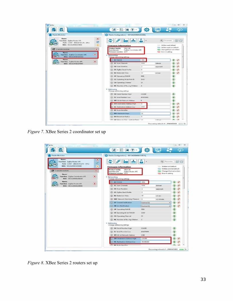
Figure 7. XBee Series 2 coordinator set up
Figure 8. XBee Series 2 routers set up
33
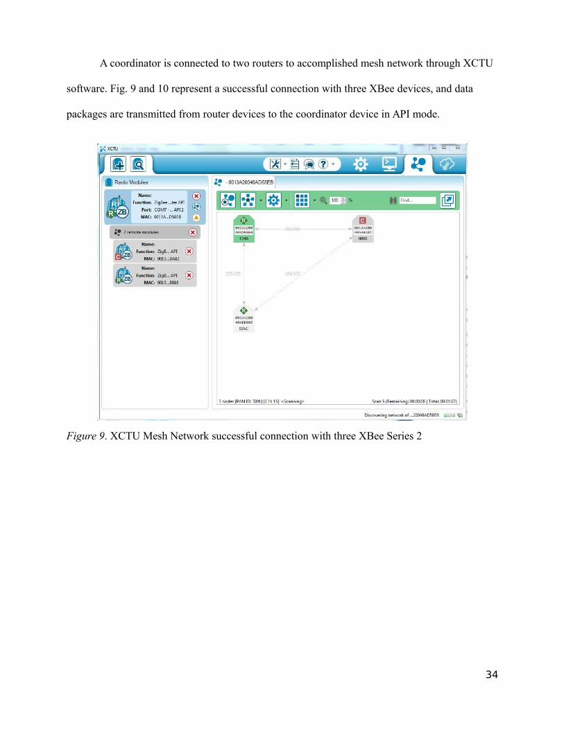
A coordinator is connected to two routers to accomplished mesh network through XCTU
software. Fig. 9 and 10 represent a successful connection with three XBee devices, and data
packages are transmitted from router devices to the coordinator device in API mode.
Figure 9. XCTU Mesh Network successful connection with three XBee Series 2
34
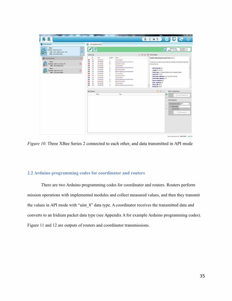
Figure 10. Three XBee Series 2 connected to each other, and data transmitted in API mode
2.2 Arduino programming codes for coordinator and routers
There are two Arduino programming codes for coordinator and routers. Routers perform
mission operations with implemented modules and collect measured values, and then they transmit
the values in API mode with “uint_8” data type. A coordinator receives the transmitted data and
converts to an Iridium packet data type (see Appendix A for example Arduino programming codes).
Figure 11 and 12 are outputs of routers and coordinator transmissions.
35
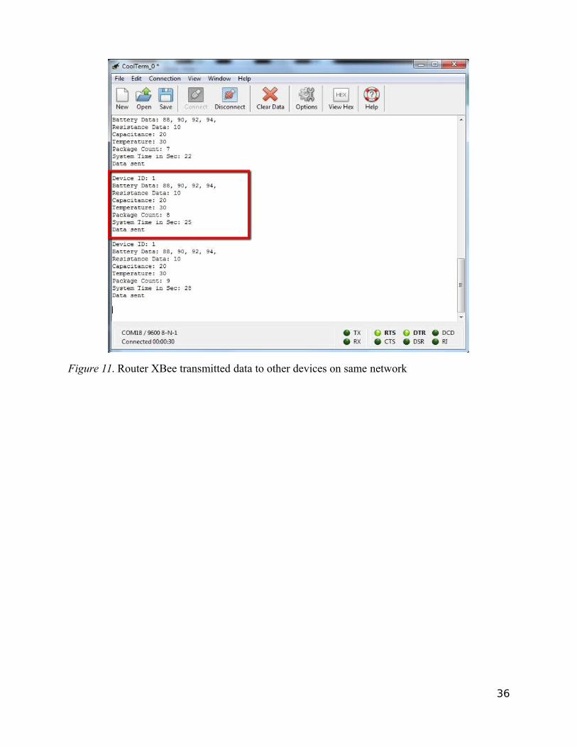
Figure 11. Router XBee transmitted data to other devices on same network
36
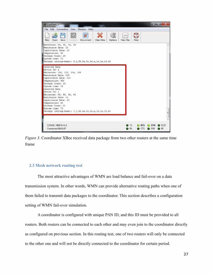
Figure 3. Coordinator XBee received data package from two other routers at the same time
frame
2.3 Mesh network routing test
The most attractive advantages of WMN are load balance and fail-over on a data
transmission system. In other words, WMN can provide alternative routing paths when one of
them failed to transmit data packages to the coordinator. This section describes a configuration
setting of WMN fail-over simulation.
A coordinator is configured with unique PAN ID, and this ID must be provided to all
routers. Both routers can be connected to each other and may even join to the coordinator directly
as configured on previous section. In this routing test, one of two routers will only be connected
to the other one and will not be directly connected to the coordinator for certain period.
37
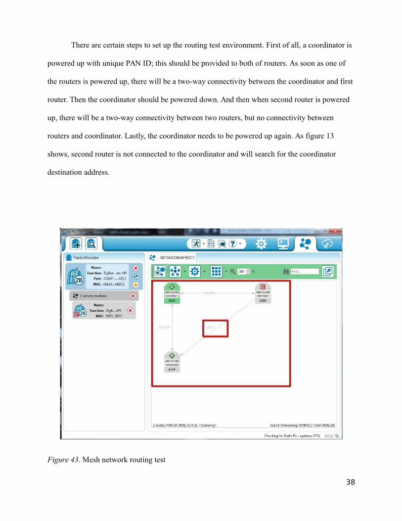
There are certain steps to set up the routing test environment. First of all, a coordinator is
powered up with unique PAN ID; this should be provided to both of routers. As soon as one of
the routers is powered up, there will be a two-way connectivity between the coordinator and first
router. Then the coordinator should be powered down. And then when second router is powered
up, there will be a two-way connectivity between two routers, but no connectivity between
routers and coordinator. Lastly, the coordinator needs to be powered up again. As figure 13
shows, second router is not connected to the coordinator and will search for the coordinator
destination address.
Figure 43. Mesh network routing test
38
3. XTend 900 for level-2 communication
Ahmed (2012) describes XTend-900 device has an incredible wide range up to 40 miles
with the low-power consumption rates; indoors it can go up to 3000ft. And this has an attached
RP-SMA antenna connector and uses Frequency Hopping Spread Spectrum to avoid interference
by moving to new frequency on every packet transmission. This transmits data among small
satellites until the maximum capable range.
C. Iridium Link Budget
A link budget is actually accounting of simple calculation of gains and losses within an
RF link. The result is an estimate at the end of system performance. A number of factors must be
considered for an accurate value, such as the uplink power amplifier gain, noise factors, transmit
antenna gain, slant angles, atmospheric loss over distance, satellite transponder noise levels, etc
(Larson, 2005).
Link budget needs the following information (Dey, 2014):
• Latitude and longitude of the uplink and downlink earth stations
• Planned data or information rate
• Modulation type (BPSK or QPSK)
• Forward error correction rate (1/2 or 3/4)
• Spread Factor - if any (use only for spread spectrum systems)
• Uplink and Downlink frequencies
• Uplink and Downlink antenna sizes
• Uplink and Downlink antenna efficiency
39
• Uplink and Downlink transmit and receive gains at frequency
• Minimum digital signal strength (EB/No) for desired Bit Error Rate (BER) performance
Link budget calculation involves (Dey, 2014):
• To minimize the cost of spacing one satellite in the proper channel in space for better
Communication
• To respond to the real-world problem by proposing effective power calculation
• To control the satellite orbiting in the range of our requirements
• Losses control
• Equivalent isotropic radiated power (EIRP) Calculation
• FSL calculation
• Carrier to noise ratio calculation
• BER (Bit Error Ratio) performance
• The losses experienced by the signal fall within these categories:
• Free Space Loss (FSL)
• Rain
• Oxygen
• Antenna Misalignment
In link budget calculation, the carrier-to-noise ratio (C/N) is a measurement of the
received carrier power relative to the strength of the received noise. Here is the equation how
to calculate for C/N.
40
a) The Received carrier power is
= ∗ =
b) Transmit gain is
= ∗ � � = ∗ ( )
c) Footprint area can be derived from Transmit gain equation.= ∗
d) Receive gain is=
e) Receiver equivalent area is=
f) The equation of EIRP is
g) Free space loss is
= � �
h) Received carrier power is
��
()
==
=∗
� �
i) Thermal noise power in bandwidth B
(1)
(1)
(2)
(3)
(5)
(4)
(5)
(6)
== (7)
Where the spectral noise density is
= (8)
j) The system temperature T and Boltzmann’s constant is
= .− / (9)
41
[ ] = −228.6 dBW K Hz
k) Carrier to noise ratio
= (10)
l) Carrier to noise density ratio
= = (11)
Then the link budget equation is expressed in logarithmic (dB) form as follows
(dB values indicated by brackets):
Uplink budget:
�
� = [] + � � − [ ] − [ ] − [ ] − [ ] (12)
Downlink budget:
�� = [] + � � − [ ] − [ ] − [ ] − [ ] (13)
Total link budget:
� �
=
� �
+
�� (14)
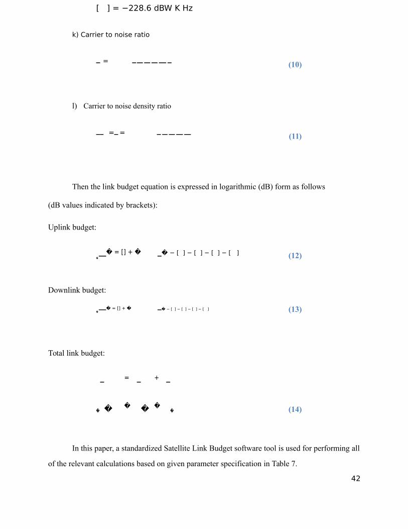
In this paper, a standardized Satellite Link Budget software tool is used for performing all
of the relevant calculations based on given parameter specification in Table 7.
42
Table 7
Iridium Link Budget parameter specification
Parameter SpecificationBandwidth 1626 MHzUplink frequency 6.175 GHz, C-bandUplink antenna diameter 1.5 mUplink antenna aperture efficiency 0.65Uplink antenna power 850 WRange 38500 kmUplink G/T 2Downlink antenna diameter 10 mDownlink noise temp. 130 KDownlink EIRP 36 dBWNote. These are arbitrary values based on the options of antennas, bandwidth, ranges etc.
Figure 54. Satellite link budget calculator (Johnston, E. 2015)43
D. PKI technology
1. PKI MethodologyAt present there isn’t a standardized data transaction security protocol between small
satellites and ground based control center. A failure of data protection can cause enormous
damages to gov’t, organization, commercial company, and even individual. I am suggesting PKI
technology for securing communication between satellites and control center. Liu (2013) stated,
“PKI is a well-known asymmetric key encryption methodology to protect data and provide
authentication. A public key infrastructure (PKI) is the combination of software, encryption
technologies, processes, and services that enable an organization to secure its communications
and business transactions.” The ability of PKI to secure communication and business
transactions is based on the exchange of digital certificates between authenticated users and
trusted resources.
You can design a PKI solution to meet the following security and technical requirements
of your organization (Liu & Tuey, 2013):
• Confidentiality. You use PKI to encrypt data that is stored or transmitted.
• Integrity. You use PKI to digitally sign data. A digital signature helps you identify
whether another user or process modified the data.
• Authenticity. PKI provides several authenticity mechanisms. Authentication data passes
through hash algorithms, such as Shivest Hash Algorithm 1 (SHA1), to produce a
message digest. Then the message digest is digitally signed by using the sender’s private
key to prove that the message digest was produced by the sender.
• Nonrepudiation. When data is digitally signed, the digital signature provides proof of
the integrity of the signed data and proof of the origin of the data. A third party can verify
44
the integrity and origin of the data at any time. This verification cannot be refuted by the
owner of the certificate that digitally signed the data.
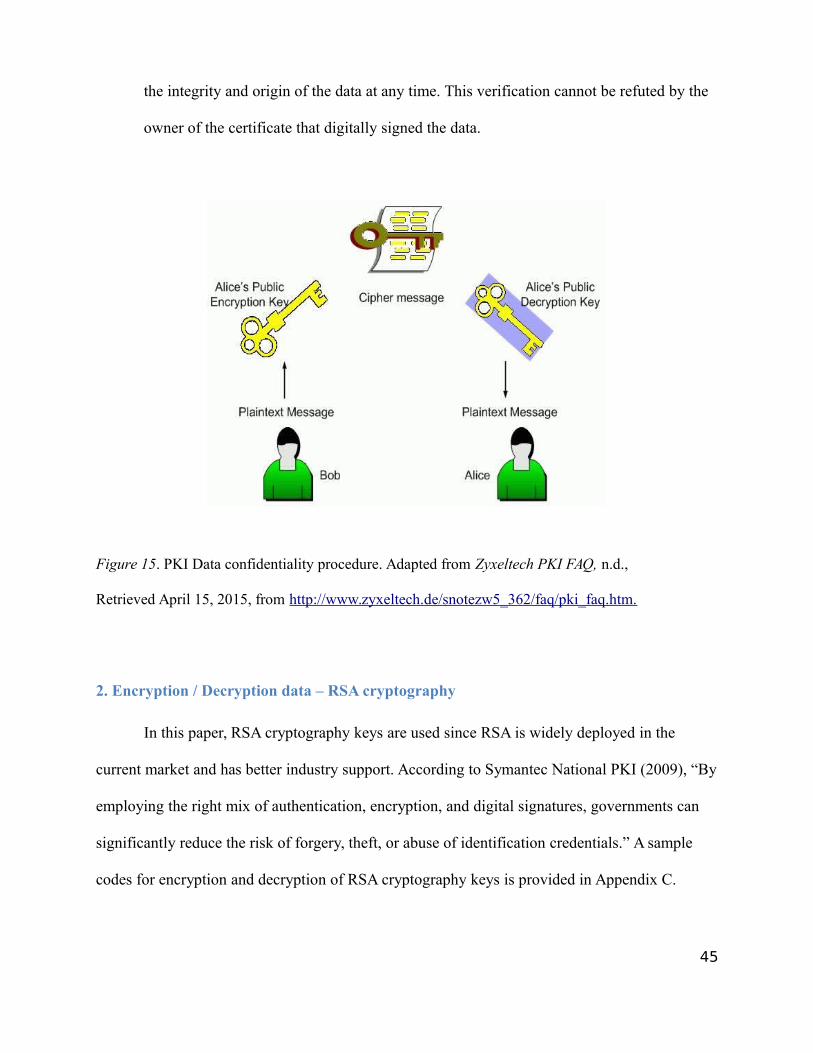
Figure 15. PKI Data confidentiality procedure. Adapted from Zyxeltech PKI FAQ, n.d.,
Retrieved April 15, 2015, from http://www.zyxeltech.de/snotezw5_362/faq/pki_faq.htm.
2. Encryption / Decryption data – RSA cryptography
In this paper, RSA cryptography keys are used since RSA is widely deployed in the
current market and has better industry support. According to Symantec National PKI (2009), “By
employing the right mix of authentication, encryption, and digital signatures, governments can
significantly reduce the risk of forgery, theft, or abuse of identification credentials.” A sample
codes for encryption and decryption of RSA cryptography keys is provided in Appendix C.
45
First, public keys are distributed to clients (satellites) on the same network from
Certificate Authority. And each coordinator operating system of satellites should have both
private and public keys in a file directory. Before encrypting a file with a public key, data file
and public key should be in same directory; “ls -all” command can verify the information on
terminal. To encrypt a data file, “Openssl” package is required. This is an open source toolkit for
SSL/TLS, and this can be downloaded and installed from openssl.org site (Czeskis, n.d.). Using
commands in the toolkit requires specific command usage format. An example of “Openssl”
command usage format for encryption is in Appendix C.
Decryption of encrypted files has same procedure as encryption, but it requires a
private key to unlock the encrypted files. Since a private key is unique one, only encrypted
files can be decrypted by the corresponded private key. “Openssl” has different command
usage format for decryption with specific parameters (Czeskis, n.d.). An example of using
“Openssl” command usage format for decryption is in Appendix C.
46
IV. Discussion and Future Work
As illustrated on the preceding sections, through a number of advanced network and
data security technologies, a standardized communication has been demonstrated that can be
adapted to small satellite mission projects. However, there are further tasks left for future work.
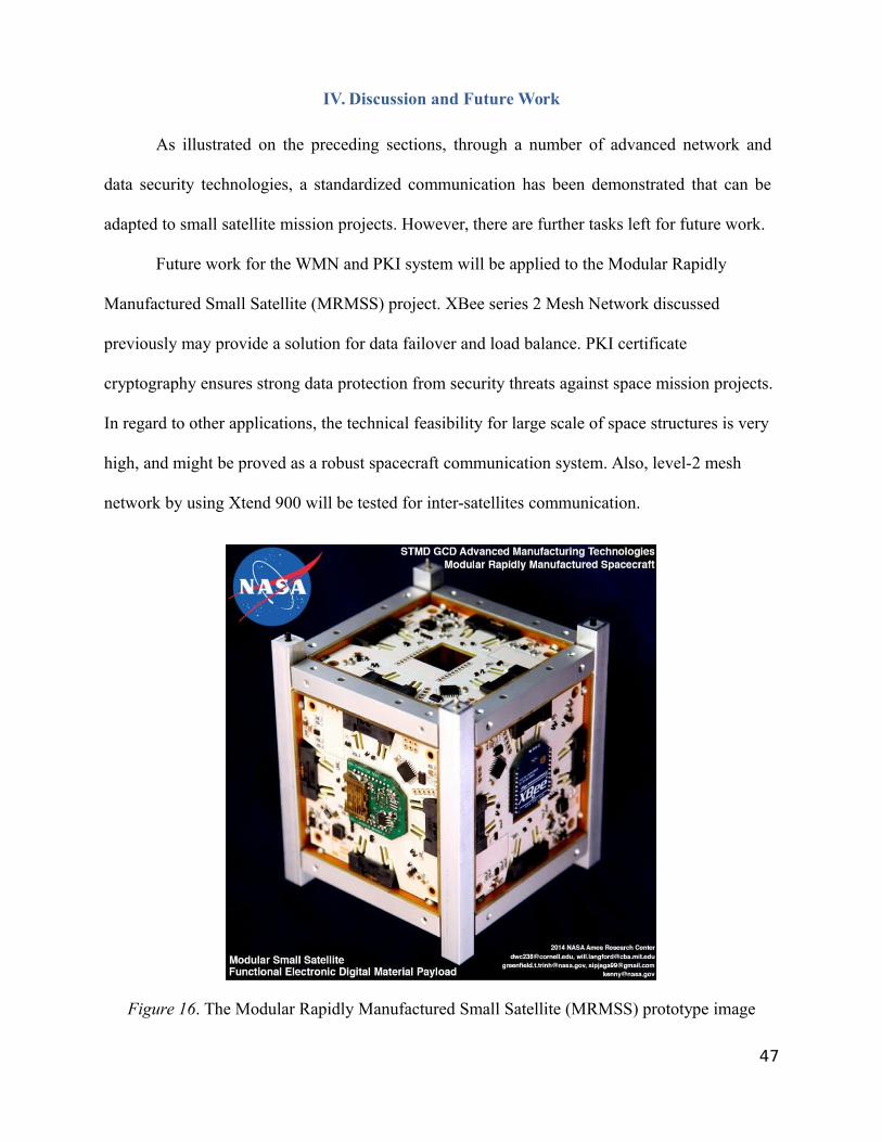
Future work for the WMN and PKI system will be applied to the Modular Rapidly
Manufactured Small Satellite (MRMSS) project. XBee series 2 Mesh Network discussed
previously may provide a solution for data failover and load balance. PKI certificate
cryptography ensures strong data protection from security threats against space mission projects.
In regard to other applications, the technical feasibility for large scale of space structures is very
high, and might be proved as a robust spacecraft communication system. Also, level-2 mesh
network by using Xtend 900 will be tested for inter-satellites communication.
Figure 16. The Modular Rapidly Manufactured Small Satellite (MRMSS) prototype image
47
V. Conclusion
A standardized network communication for small satellites that include WMN, world-
wide satellite communication, and PKI technology has been proposed in this paper. 2-level of
WMN has been developed with XBee Series 2 and Xtend 900. World-wide satellite
communication service, Iridium, provides continuous internet accessibility for transmitting data
from small satellites to ground stations. Open-source version of PKI technology for data
transaction has an ability to securely protect data from satellites to ground-based users safely by
using a paired key usage algorithm. In addition, RFI prevention has been included with its
intended software, ComSitePro, by analyzing and measuring RFI rates into satellites.
This network communication is very efficient for low budget and mass production space
mission projects with advanced features. I hope that this paper can contribute relevant
information for engineers and students who are interested to develop their own satellite projects.
48
VI. References
Ahmed, R. (2012). Wireless Network System Based Multi-Non-Invasive Sensors for Smart Home.
Retrieved from https://curve.carleton.ca/system/files/theses/28802.pdf
Akyildiz, I., & Wang, X. (2004). Wireless mesh networks:a survey. Bridgewater, NJ: Elsevier
B.V.
Alan, G. (2012). Gottlieb’s Focus: Iridium, Inmarsat + Globalstar: Which service is best? Journal of
SatMagazine. Retrieved from http://www.satmagazine.com/story.php?number=242951891
Cockrell, J. (2012). EDSN: A Large Swarm of Advanced Yet Very Affordable, COTS-based
NanoSats that Enable Multipoint Physics and Open Source Apps.
ComSitePro Wireless Site Engineering. (2014). Retrieved from
http://www.rcc.com/comsite/comsitepro.shtml
Czeskis, A. (n.d.). How to encrypt a big file using OpenSSL and someone's public key. Retrieved
March 20, 2015, from http://www.czeskis.com/random/openssl-encrypt-file.html
Davis, G. (2011). History of the NOAA satellite program. Journal of Applied Remote
Sensing, 012504-012504.
Dey, S., Mohapatra, D., & Archana. S. (2014). An Approach to calculate the Performance and
Link Budget of LEO Satellite (Iridium) For Communication Operated at frequency Range
(1650-1550) MHz.
Elbert, B. (2004). The Satellite Communication Applications Handbook. (2nd ed.). Norwood, MA:Artech House, Inc.
Johnston, E. (2015). Satellite Signal: Satellite Link Budget Calculator [Software]. Available
from http://www.satsig.net/linkbugt.htm
Kevin, A. (2009, June 22). That ‘Internet of Things’ Thing. RFID Journal. Retrieved from
http://www.rfidjournal.com/articles/view?4986
Larson, W., Wertz, J., (2005). Space Mission Analysis and Design, Third Edition. El Segundo,
CA: Microcosm Press.
Liu, Y., & Tuey, R. (2013). Modeling, Simulation and Analysis of PKI. 22- 22.
Manchester, Z., Mason P., & Andrew Filo. (2013). KickSat: A Crowd-Funded Mission to
Demon-strate the WorldâĂŹs Smallest Spacecraft.
Matt, T., (2014, Oct 4). Security Expert raises Issues of Satcom Vulnerabilities. AINonline.
49
Retrieved from http://www.ainonline.com/aviation-news/2014-10-04/security-expert-raises-
issues-satcom-vulnerabilities
Mohammed A., & Md. Shohrab H. (2011). Security Issues in Space Network. NASA Earth
Science Technology.
Symantec White Paper - National PKI. (2011, January 1). Retrieved March 15, 2015, from
https://www4.symantec.com/mktginfo/whitepaper/user_authentication/21195844_WP_G\A_Ntnl
PKIFoundationTrust_070111.pdf
The Case for Elliptic Curve Cryptography. (2009, January 15). Retrieved April 27, 2015, from
https://www.nsa.gov/business/programs/elliptic_curve.shtml
Thurber, M. (2014, October 4). Security Expert Raises Issues of Satcom Vulnerabilities. Aviation
International News. Retrieved April 10, 2015, from http://www.ainonline.com/aviation-
news/2014-10-04/security-expert-raises-issues-satcom-vulnerabilities
Trinh, G., Cellucci, D., Langford, W., Im, S., Luna, A., & Cheung, K. (2015). Modular Rapidly
Manufactured Small Satellite.
Werner, D. (2012, January 23). Hacking Cases Draw Attention To Satcom Vulnerabilities.Defense News. Retrieved April 10, 2015, fromhttp://archive.defensenews.com/article/20120123/C4ISR02/301230010/Cover-Story-Hacking-Cases-Draw-Attention-Satcom-Vulnerabilities
50
VII. Appendices
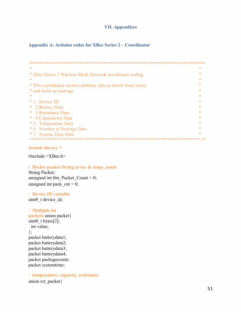
Appendix A: Arduino codes for XBee Series 2 – Coordinator
/*************************************************************************** ** Xbee Series 2 Wireless Mesh Network coordinator coding ** ** This coordinator receive arbitrary data as below from router ** and build up package ** ** 1. Device ID ** 2.Battery Data ** 3.Resistance Data ** 4.Capacitance Data ** 5. Temperature Data ** 6. Number of Package Data ** 7. System Time Data ****************************************************************************/ /*
Include library */
#include <XBee.h>
/ Declar packet String array & temp_countString Packet;unsigned int tlm_Packet_Count = 0;unsigned int pack_cnt = 0;
/ Device ID variableuint8_t device_id;
/ Multiple int packets union packet{uint8_t bytes[2];int value;
};packet batterydata1; packet batterydata2; packet batterydata3; packet batterydata4; packet packagecount;packet systemtime;
/ temperature, capacity, resistanceunion rct_packet{
51
uint8_t bytes[2];int value;
};rct_packet rctData1;rct_packet rctData2;rct_packet rctData3;
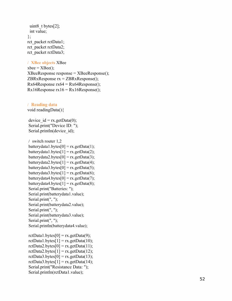
/ XBee objects XBeexbee = XBee();XBeeResponse response = XBeeResponse();ZBRxResponse rx = ZBRxResponse(); Rx64Response rx64 = Rx64Response(); Rx16Response rx16 = Rx16Response();
/ Reading datavoid readingData(){
device_id = rx.getData(0);Serial.print("Device ID: ");Serial.println(device_id);
/ switch router 1,2 batterydata1.bytes[0] = rx.getData(1); batterydata1.bytes[1] = rx.getData(2); batterydata2.bytes[0] = rx.getData(3); batterydata2.bytes[1] = rx.getData(4); batterydata3.bytes[0] = rx.getData(5); batterydata3.bytes[1] = rx.getData(6); batterydata4.bytes[0] = rx.getData(7); batterydata4.bytes[1] = rx.getData(8); Serial.print("Batteries: "); Serial.print(batterydata1.value); Serial.print(", "); Serial.print(batterydata2.value); Serial.print(", "); Serial.print(batterydata3.value); Serial.print(", "); Serial.println(batterydata4.value);
rctData1.bytes[0] = rx.getData(9);rctData1.bytes[1] = rx.getData(10);rctData2.bytes[0] = rx.getData(11);rctData2.bytes[1] = rx.getData(12);rctData3.bytes[0] = rx.getData(13);rctData3.bytes[1] = rx.getData(14);Serial.print("Resistance Data: ");Serial.println(rctData1.value);
52
Serial.print("Capacitance Data: ");Serial.println(rctData2.value);Serial.print("Temperature: ");Serial.println(rctData3.value);
packagecount.bytes[0] = rx.getData(15);packagecount.bytes[1] = rx.getData(16);systemtime.bytes[0] = rx.getData(17);systemtime.bytes[1] = rx.getData(18);Serial.print("Package Count: ");Serial.println(packagecount.value);Serial.print("System time: ");Serial.println(systemtime.value);
pack_cnt = pack_cnt + 1;}
/////////////////////////////////////////////////////////////////////////////////////////////////////////////////////////////Function: Build Packet//Type: Void////This function constructs the packet to be sent over Iridium/////////////////////////////////////////////////////////////////////////////////////////////////////////////////////////////void build_packet(){
String temp_value;
// Assign Packet Numbertlm_Packet_Count = tlm_Packet_Count+1;temp_value = String(tlm_Packet_Count);Packet = temp_value;Packet = String(Packet + ",");
// Transfer Device IDtemp_value = String(device_id, HEX);Packet = String(Packet + temp_value);Packet = String(Packet + ",");
/ Transfer battery usage data into Packet[] temp_value = String(batterydata1.value, HEX); Packet = String(Packet + temp_value); Packet = String(Packet + ",");
temp_value = String(batterydata2.value, HEX);Packet = String(Packet + temp_value);Packet = String(Packet + ",");
53
temp_value = String(batterydata3.value, HEX);Packet = String(Packet + temp_value);Packet = String(Packet + ",");
temp_value = String(batterydata4.value, HEX);Packet = String(Packet + temp_value);Packet = String(Packet + ",");
// Transfer will data into Packet[]temp_value = String(rctData1.value, HEX);Packet = String(Packet + temp_value);Packet = String(Packet + ",");
temp_value = String(rctData2.value, HEX);Packet = String(Packet + temp_value);Packet = String(Packet + ",");
temp_value = String(rctData3.value, HEX);Packet = String(Packet + temp_value);Packet = String(Packet + ",");
// Transfer Packet Count into Packet[]temp_value = String(packagecount.value, HEX); Packet = String(Packet + temp_value); Packet = String(Packet + ",");
// Transfer System Time into Packet[]temp_value = String(systemtime.value, HEX);Packet = String(Packet + temp_value);
}
void setup(){
Serial.begin(9600);Serial3.begin(9600);xbee.setSerial(Serial3);Serial.println("Begin reading data");
}
void loop(){
xbee.readPacket(1000);if (xbee.getResponse().isAvailable()){Serial.println("received Data");
if (xbee.getResponse().getApiId() == ZB_RX_RESPONSE)
54
{//Read the packetxbee.getResponse().getZBRxResponse(rx);readingData();
if (pack_cnt == 2){/ Build packet - convertbuild_packet(); pack_cnt = 0;
Serial.print("Package (string-hexa): ");Serial.println(Packet);Serial.println();
} //packet buildup} // xbee.getResponse
} // xbee.isAvailable} // loop
55
Appendix B: Arduino codes for Xbee Series 2 - routers
/**************************************************************************
* ** Xbee Series 2 Wireless Mesh Network Router coding ** ** This router transmits arbitrary data as below to coordinator Xbee ** 1. Device ID ** 2.Battery Data ** 3.Resistance Data ** 4.Capacitance Data ** 5. Temperature Data ** 6. Number of Package Data ** 7. System Time Data ****************************************************************************/
/* Include library */#include "Arduino.h"#include "Wire.h"#include "MAX1704.h"#include "XBee.h"#include "math.h"
/* Data package */uint8_t packet1[19];
int num_batt = 4;int num_pack = 0;int charge_int = 0;int current_time = 0;XBee xbee = XBee();unsigned long start =0;
/* Union type Data - for conversion of byte to int */ union Data{uint8_t bytes[2];int value;
};
Data batterydata;Data resdata;Data capdata;Data tempdata;Data packcnt;Data packtime;
/* Xbee Series 2 package transmitt */
56
XBeeAddress64 addr64 = XBeeAddress64(0x0013A200, 0x40B4502C);
ZBTxRequest tx = ZBTxRequest(addr64,packet1, sizeof(packet1));
//TxStatusResponse txStatus = TxStatusResponse(); ZBTxStatusResponse txStatus = ZBTxStatusResponse();
//Add battery voltageData to package1void voltageData(int charval,int cnt){batterydata.value = charval;packet1[cnt] = batterydata.bytes[0];packet1[cnt+1] = batterydata.bytes[1];
Serial.print(batterydata.value);}
//Add temperature, capacity, resistance to package1void tcrData(int res, int cap, int temp){resdata.value = res;capdata.value = cap;tempdata.value = temp;
packet1[9] = resdata.bytes[0];packet1[10] = resdata.bytes[1];
packet1[11] = capdata.bytes[0];packet1[12] = capdata.bytes[1];
packet1[13] = tempdata.bytes[0];packet1[14] = tempdata.bytes[1];Serial.print("Resistance Data: ");Serial.println(resdata.value);Serial.print("Capacitance: ");Serial.println(capdata.value);Serial.print("Temperature: ");Serial.println(tempdata.value);
}
//Add package count to packet1void packagecount(int charval){packcnt.value = charval;packet1[15] = packcnt.bytes[0];packet1[16] = packcnt.bytes[1];
Serial.print("Package Count: ");Serial.println(packcnt.value);
57
}
//Add System time in seconds to packet1void systemtime(int charval){packtime.value = charval;packet1[17] = packtime.bytes[0];packet1[18] = packtime.bytes[1];
Serial.print("System Time in Sec: ");Serial.println(packtime.value);}
/ Transmit package through Xbeevoid transmit(){xbee.send(tx);if (xbee.readPacket(5000)) {if (xbee.getResponse().getApiId() == TX_STATUS_RESPONSE) {xbee.getResponse().getZBTxStatusResponse(txStatus);if (txStatus.getDeliveryStatus() == SUCCESS) {/ success. time to celebrate delay(3000);
}else {/ the remote XBee did not receive our packet. is it powered on? //Serial.println("Reomte XBee didn't receive our packet. Is it powered on?");
}} //xbee.getResponse()
}//xbee.readPacket();else if (xbee.getResponse().isError()) { //"Error reading packet. Error code:" //Serial.println(xbee.getResponse().getErrorCode()); }//xbee.getresponse().iserror()else {// local XBee did not provide a timely TX Status Response. Radio is not configured properly
or connected}
}//end of transmit
MAX1704 fuelGauge;
void setup(){
Wire.begin();Serial.begin(9600);Serial3.begin(9600);
58
xbee.setSerial(Serial3);Serial.println("Starting up...");
fuelGauge.reset();fuelGauge.quickStart();fuelGauge.showConfig();packet1[0] = (uint8_t) 1; // Device ID
}
void loop(){
Serial.print("Device ID: ");Serial.println(packet1[0]);//float charge = fuelGauge.stateOfCharge();/ arbitrary battery datafloat charge = 88;int charge_int1 = (int) charge;int charge_int2 = (int) charge;int charge_int3 = (int) charge;int charge_int4 = (int) charge;
Serial.print("Battery Data: ");
/ first package - 4 batteries int j = 0; // data package count for (int i = 0; i < num_batt; i++){
switch(i){case 0:charge_int = charge_int1;j = i;break;
case 1:charge_int = charge_int2+2;j = i+1;break;
case 2:charge_int = charge_int3+4;j = i+2;break;
case 3:charge_int = charge_int4+6;j = i+3;break;
default:Serial.println("wrong # of switch");
59
}voltageData(charge_int,j+1);Serial.print(", ");
}Serial.println(" ");
/ arbitrary resistance, capicitance, temperature dataint resistance = 10;int capacitance = 20;int temperature = 30;tcrData(resistance, capacitance, temperature);
/ number of package countpackagecount(num_pack);
/ system time data start =millis(); start = start/1000; current_time = (int) start; systemtime(current_time);
transmit();
num_pack = num_pack++;Serial.println("Data sent");Serial.println();delay(3000);
}
60
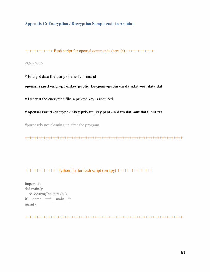
Appendix C: Encryption / Decryption Sample code in Arduino
++++++++++++ Bash script for openssl commands (cert.sh) ++++++++++++
#!/bin/bash
# Encrypt data file using openssl command
openssl rsautl -encrypt -inkey public_key.pem -pubin -in data.txt -out data.dat
# Decrypt the encrypted file, a private key is required.
# openssl rsautl -decrypt -inkey private_key.pem -in data.dat -out data_out.txt
#purposely not cleaning up after the program.
++++++++++++++++++++++++++++++++++++++++++++++++++++++++++++++++++++
++++++++++++++ Python file for bash script (cert.py) +++++++++++++++
import osdef main():
os.system("sh cert.sh")if __name__=="__main__":main()
++++++++++++++++++++++++++++++++++++++++++++++++++++++++++++++++++++
61
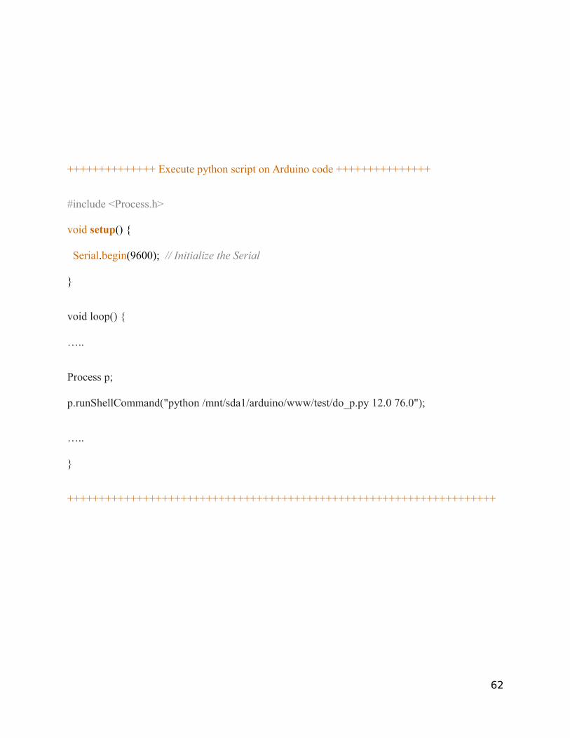
++++++++++++++ Execute python script on Arduino code +++++++++++++++
#include <Process.h>
void setup() {
Serial.begin(9600); // Initialize the Serial
}
void loop() {
…..
Process p;
p.runShellCommand("python /mnt/sda1/arduino/www/test/do_p.py 12.0 76.0");
…..
}
++++++++++++++++++++++++++++++++++++++++++++++++++++++++++++++++++++
62
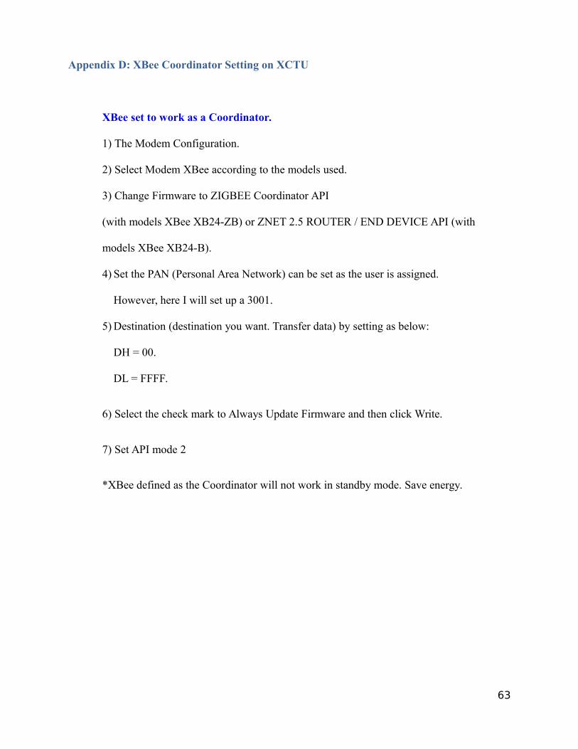
Appendix D: XBee Coordinator Setting on XCTU
XBee set to work as a Coordinator.
1) The Modem Configuration.
2) Select Modem XBee according to the models used.
3) Change Firmware to ZIGBEE Coordinator API
(with models XBee XB24-ZB) or ZNET 2.5 ROUTER / END DEVICE API (with
models XBee XB24-B).
4) Set the PAN (Personal Area Network) can be set as the user is assigned.
However, here I will set up a 3001.
5) Destination (destination you want. Transfer data) by setting as below:
DH = 00.
DL = FFFF.
6) Select the check mark to Always Update Firmware and then click Write.
7) Set API mode 2
*XBee defined as the Coordinator will not work in standby mode. Save energy.
63
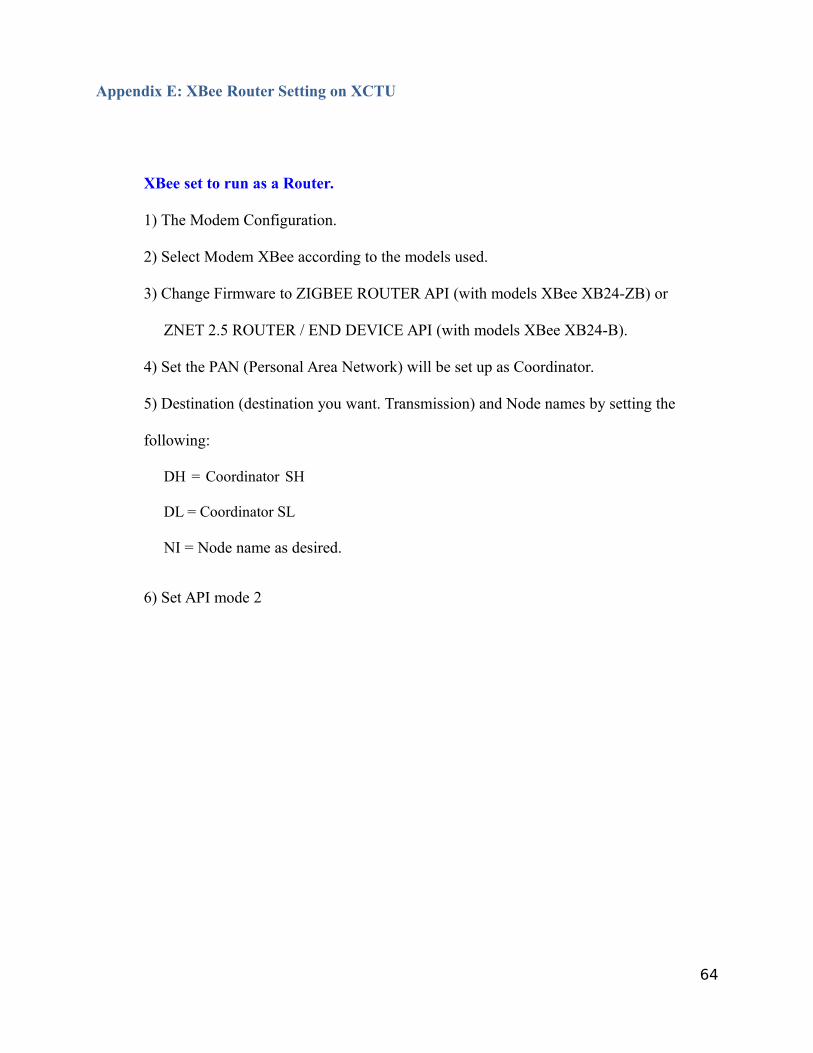
Appendix E: XBee Router Setting on XCTU
XBee set to run as a Router.
1) The Modem Configuration.
2) Select Modem XBee according to the models used.
3) Change Firmware to ZIGBEE ROUTER API (with models XBee XB24-ZB) or
ZNET 2.5 ROUTER / END DEVICE API (with models XBee XB24-B).
4) Set the PAN (Personal Area Network) will be set up as Coordinator.
5) Destination (destination you want. Transmission) and Node names by setting the
following:
DH = Coordinator SH
DL = Coordinator SL
NI = Node name as desired.
6) Set API mode 2
64