Embed Size (px)
Citation preview
Contamination FundamentalsContamination Fundamentals
Contamination
THE ENEMYTO
MODERN HYDRAULIC SYSTEMS
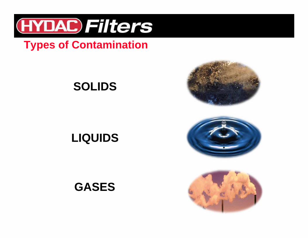
Types of Contamination
SOLIDS
LIQUIDS
GASES
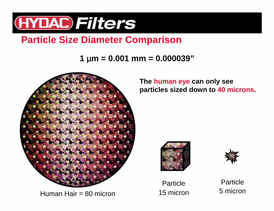
Particle Size Diameter Comparison
Human Hair = 80 micron
1 µµµµm = 0.001 mm = 0.000039”
Particle5 micron
Particle15 micron
The human eye can only see particles sized down to 40 microns .
32,00016,00015
64,00032,00016
130,00064,00017
250,000130,00018
500,000250,00019
1,000,000500,00020
2,000,0001,000,00021
4,000,0002,000,00022
8,000,0004,000,00023
16,000,0008,000,00024
32,000,00016,000,00025
64,000,00032,000,00026
130,000,00064,000,00027
250,000,000130,000,00028
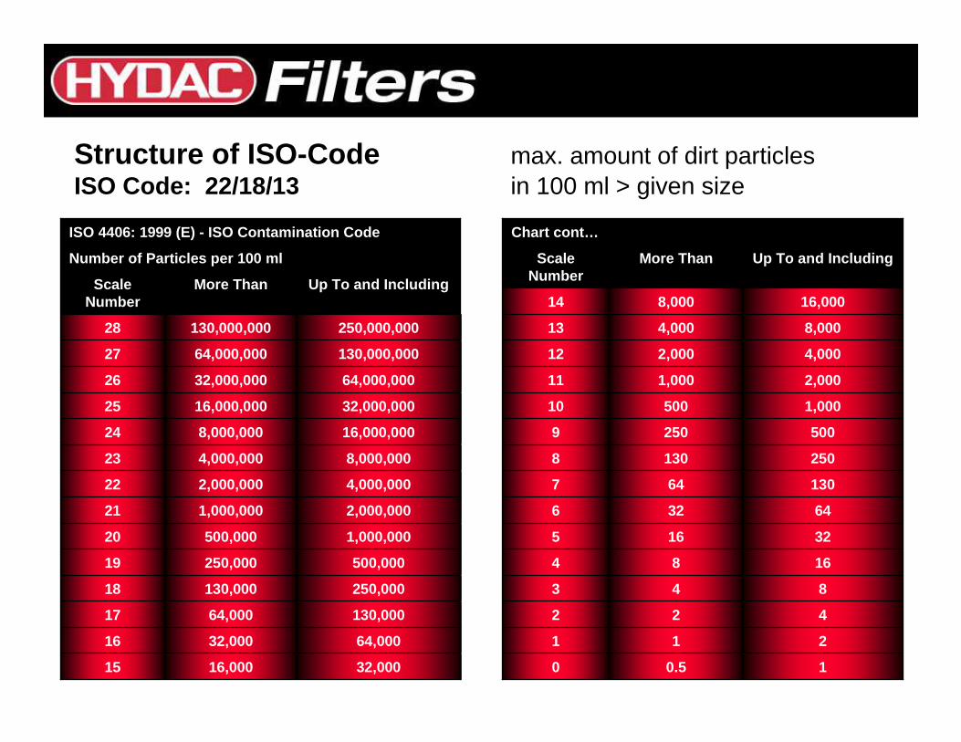
Up To and IncludingMore ThanScale Number
Number of Particles per 100 ml
ISO 4406: 1999 (E) - ISO Contamination Code
Structure of ISO-Code max. amount of dirt particlesISO Code: 22/18/13 in 100 ml > given size
10.50
211
422
843
1684
32165
64326
130647
2501308
5002509
1,00050010
2,0001,00011
4,0002,00012
8,0004,00013
16,0008,00014
Up To and IncludingMore ThanScale Number
Chart cont…
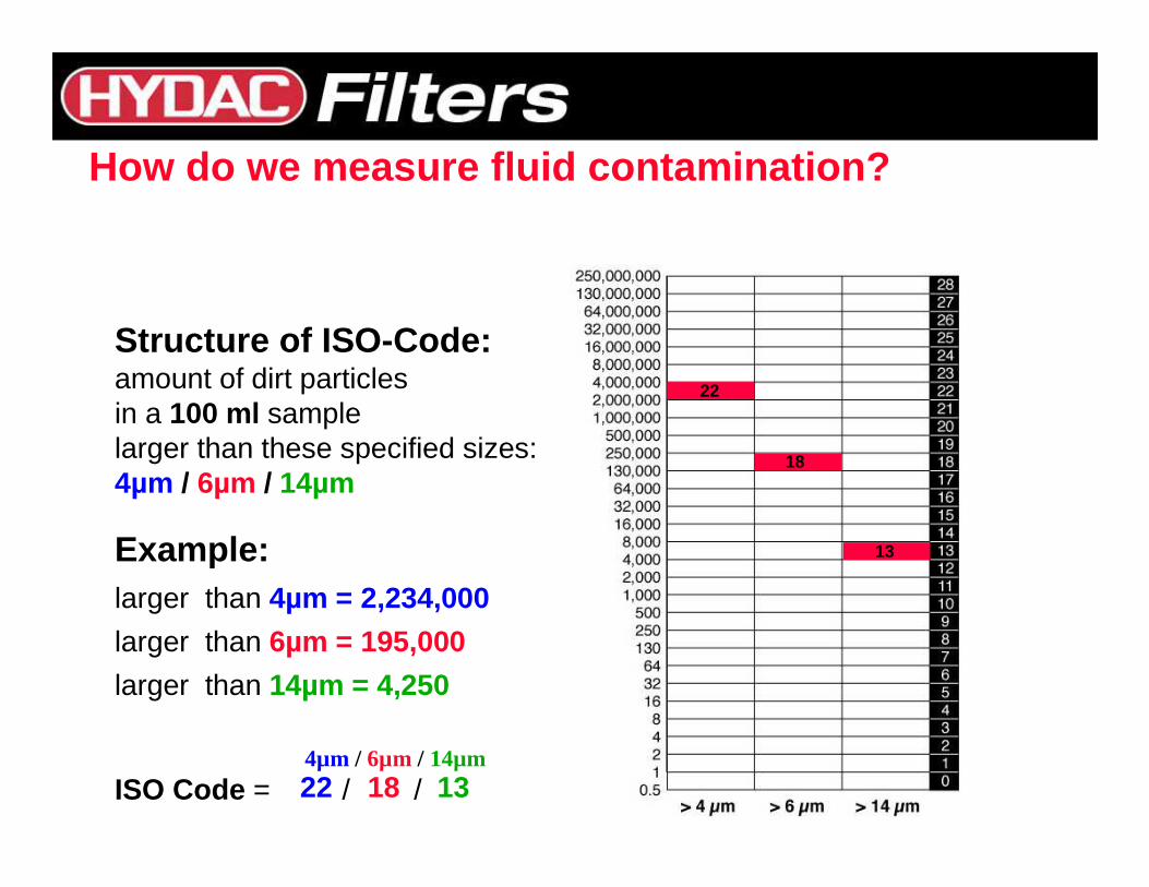
Structure of ISO-Code:amount of dirt particlesin a 100 ml samplelarger than these specified sizes:4µm / 6µm / 14µm
Example:larger than 4µm = 2,234,000
larger than 6µm = 195,000
larger than 14µm = 4,250
ISO Code = / /
22
22
18
18
13
13
How do we measure fluid contamination?
4µm / 6µm / 14µm
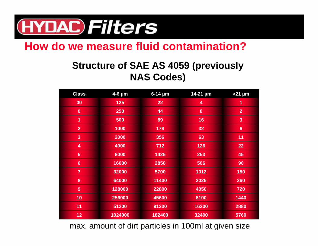
max. amount of dirt particles in 100ml at given size
576032400182400102400012
288016200912005120011
144081004560025600010
7204050228001280009
360202511400640008
18010125700320007
905062850160006
45253142580005
2212671240004
116335620003
63217810002
316895001
28442500
142212500
>21 µm14-21 µm6-14 µm4-6 µmClass
Structure of SAE AS 4059 (previously NAS Codes)
How do we measure fluid contamination?
22/21/18121,0245,76032,400182,4001,024,000221,5841,245,584
3,200,000
21/20/17115122,88016,20091,200512,000110,792622,7921,600,000
20/19/16102561,4408,10045,600256,00055,396311,396800,000
19/18/1591287204,05022,800128,00027,698155,698400,000
18/17/148643602,02511,40064,00013,84977,849200,000
17/16/137321801,0125,70032,0006,92438,924100,000
16/14/12616905062,85016,0003,46219,46250,000
15/14/1158452561,4258,0001,7319,73125,000
14/13/1044221267124,0008644,86412,500
13/12/93211633562,0004322,4326,250
12/11/8216321781,0002171,2173,120
11/10/711316895001096091,560
10/9/600284425054304780
9/8/5000142212527152390
8/7/4000---------------1476195
---------------Size Code C
Size Code B
Size Code A
> 70 um(c)38 to 70 um(c)
21 to 38 um(c)14 to 21 um(c)6 to 14 um(c)
>14 um(c)
>6 um(c)> 4 um(c)
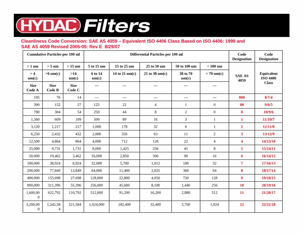
Equivalent ISO 4406
Class
SAE AS 4059
> 100 um50 to 100 um25 to 50 um15 to 25 um5 to 15 um> 15 um> 5 um> 1 um
Code Designation
Code Designation
Differential Particles per 100 mlCumulative Particles per 100 ml
Cleanliness Code Conversion: SAE AS 4059 – Equivalen t ISO 4406 Class Based on ISO 4406: 1999 and SAE AS 4059 Revised 2005-05: Rev E 8/29/07
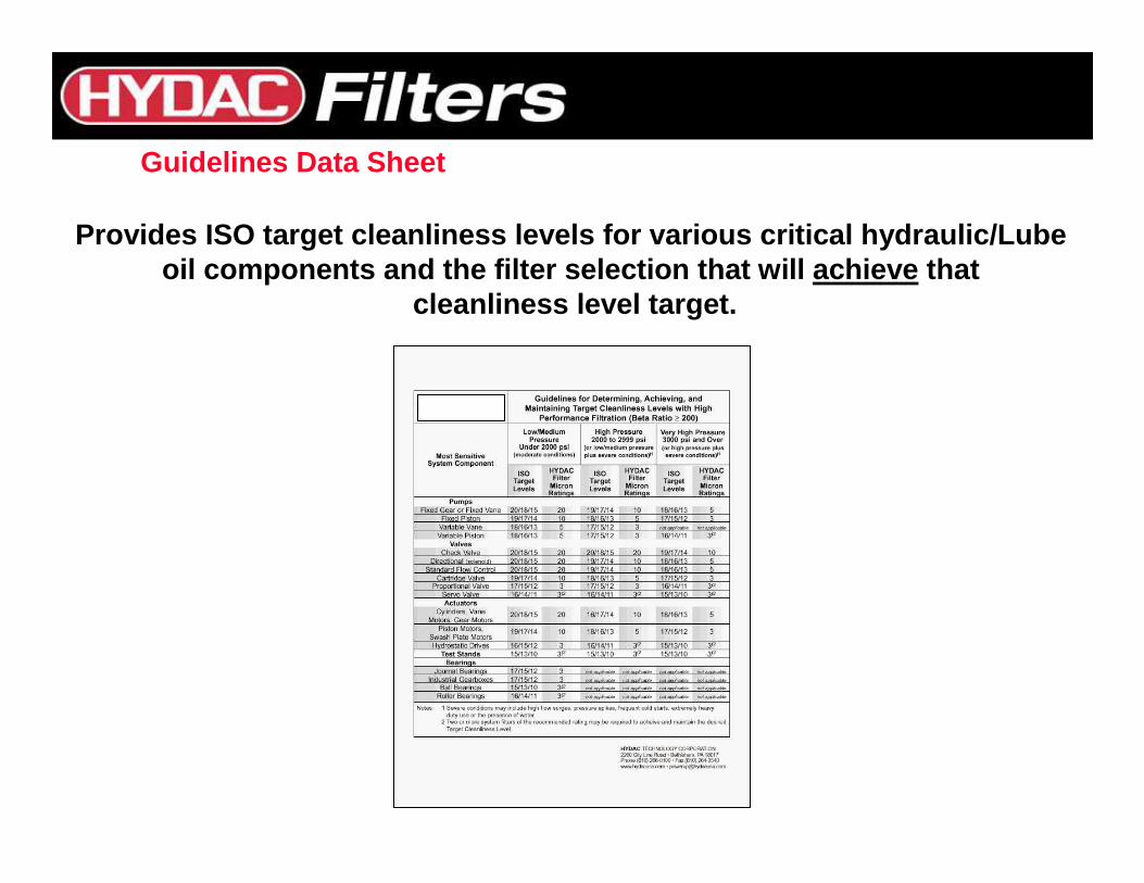
Guidelines Data Sheet
Provides ISO target cleanliness levels for various critical hydraulic/Lube oil components and the filter selection that will a chieve that
cleanliness level target.
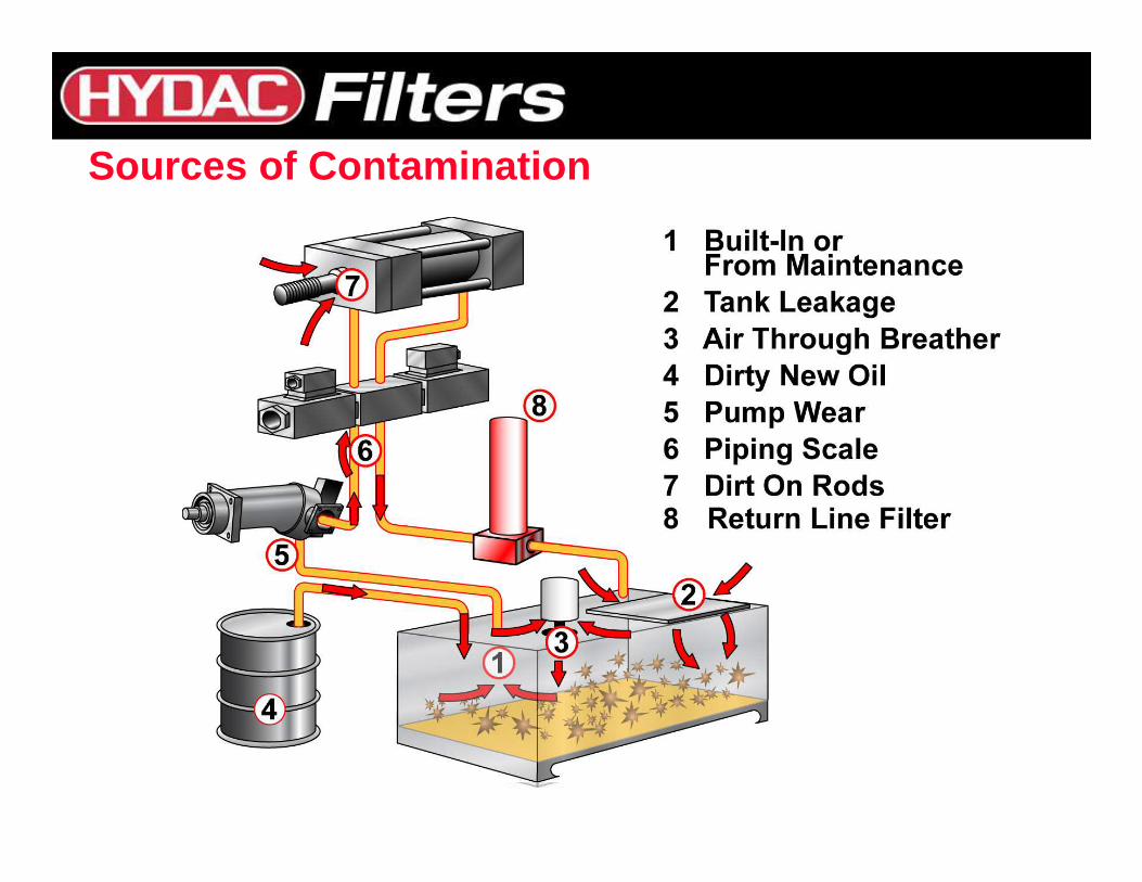
Sources of Contamination
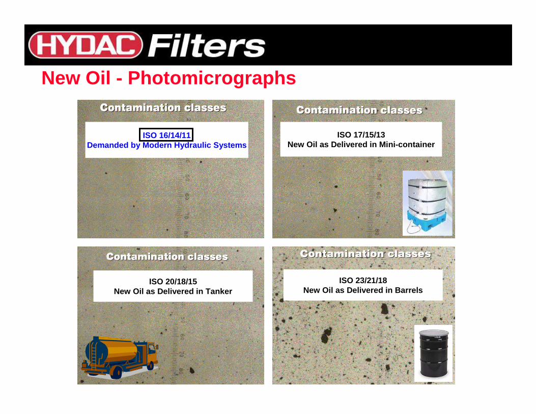
New Oil - Photomicrographs
ISO 16/14/11Demanded by Modern Hydraulic Systems
ISO 17/15/13New Oil as Delivered in Mini-container
ISO 20/18/15New Oil as Delivered in Tanker
ISO 23/21/18New Oil as Delivered in Barrels
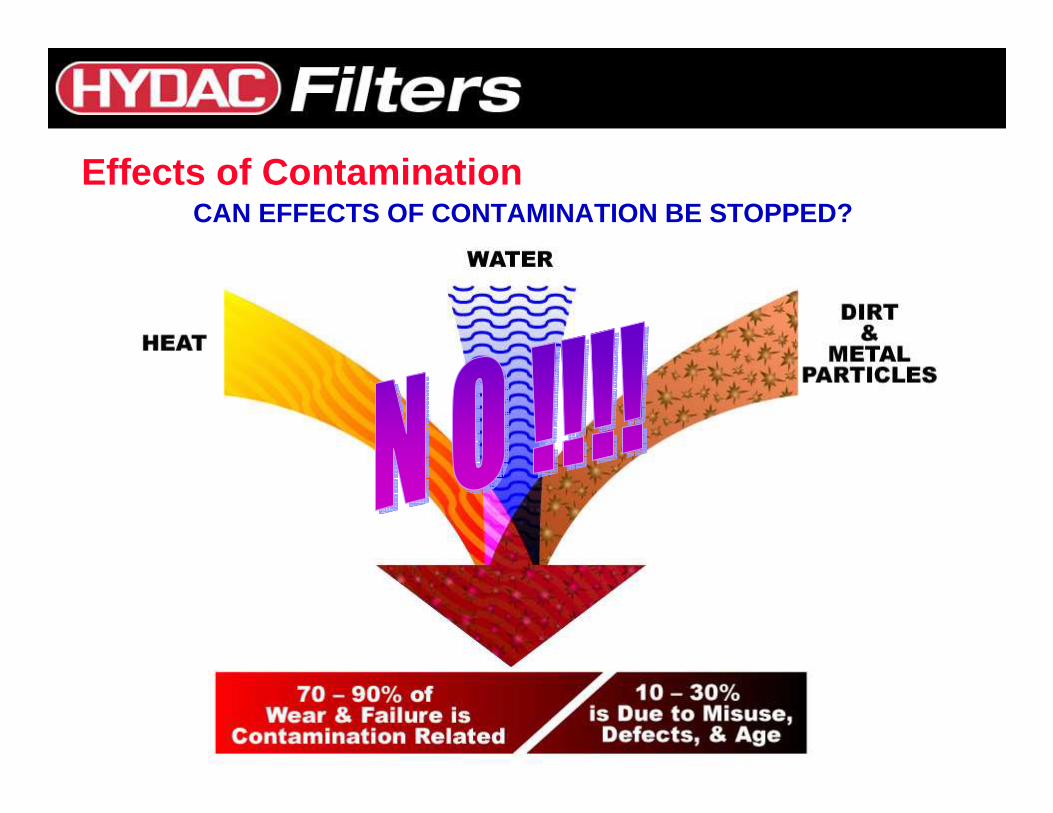
CAN EFFECTS OF CONTAMINATION BE STOPPED?Effects of Contamination
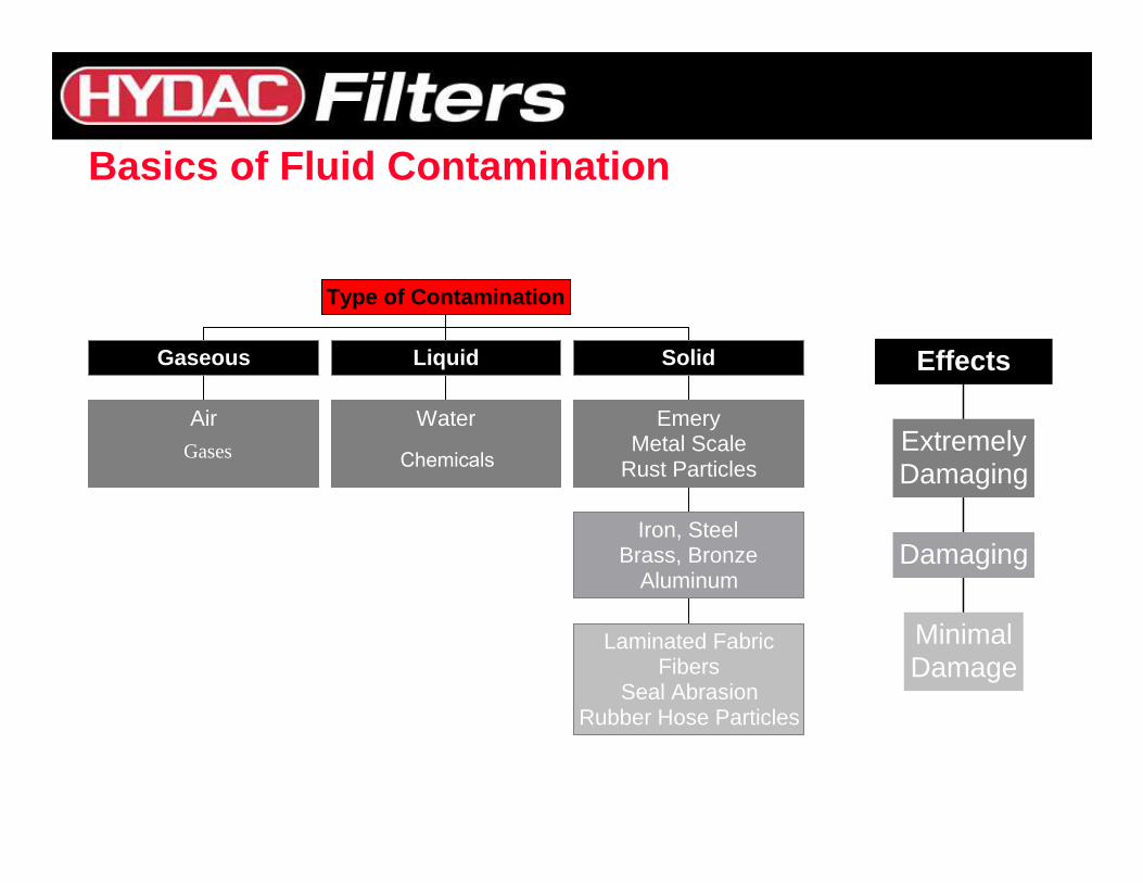
Air
Gaseous
Water
Liquid
Laminated FabricFibers
Seal AbrasionRubber Hose Particles
Iron, SteelBrass, Bronze
Aluminum
EmeryMetal Scale
Rust Particles
Solid
Type of Contamination
Basics of Fluid Contamination
MinimalDamage
Damaging
ExtremelyDamaging
Effects
ChemicalsGases
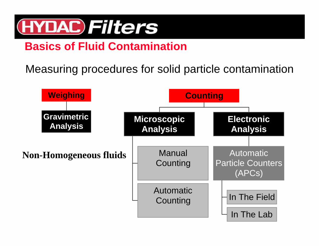
Measuring procedures for solid particle contamination
ManualCounting
AutomaticCounting
MicroscopicAnalysis
In The Field
In The Lab
AutomaticParticle Counters
(APCs)
ElectronicAnalysis
Counting
GravimetricAnalysis
Weighing
Basics of Fluid Contamination
Non-Homogeneous fluids
0
2
4
6
8
10
12
14
16
18
20
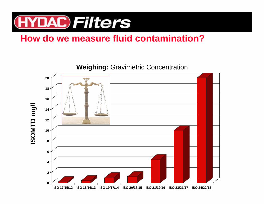
ISO 17/15/12 ISO 18/16/13 ISO 19/17/14 ISO 20/18/15 ISO 21/19/16 ISO 23/21/17 ISO 24/22/18
ISO
MT
D m
g/l
Weighing: Gravimetric Concentration
How do we measure fluid contamination?
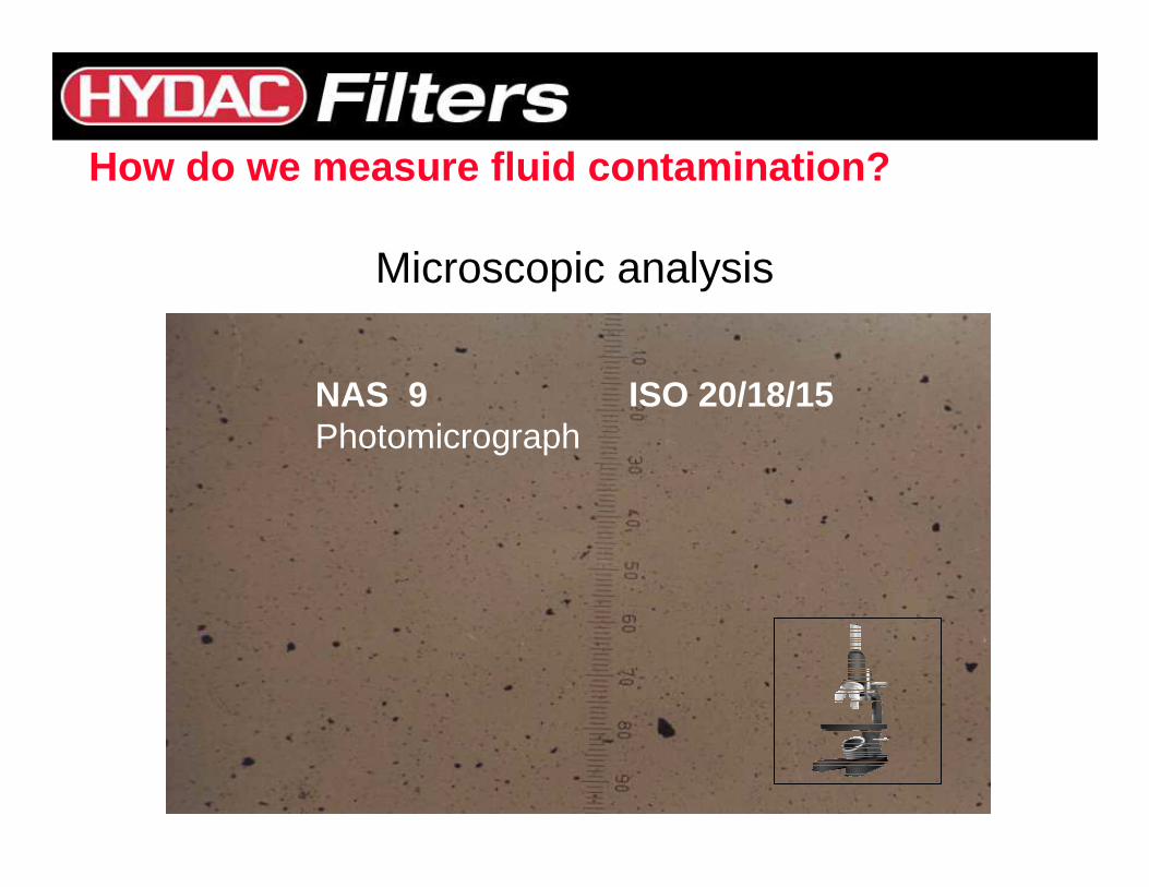
Microscopic analysis
NAS 9 ISO 20/18/15Photomicrograph
How do we measure fluid contamination?
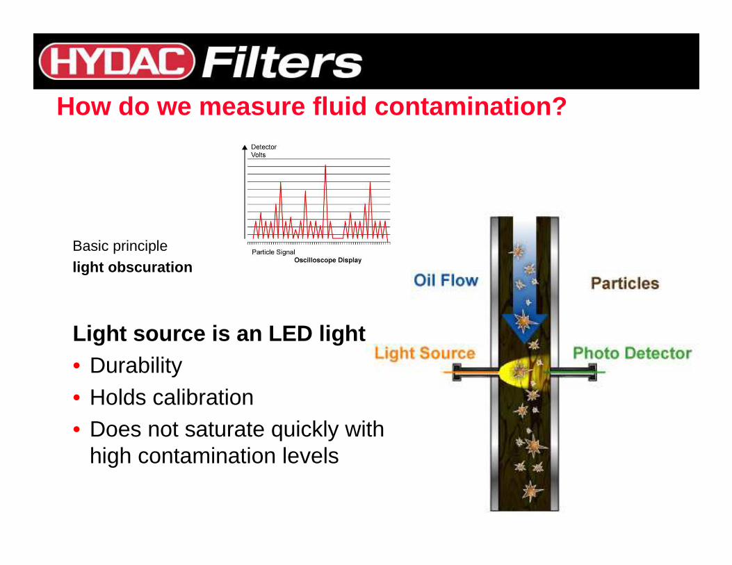
Basic principlelight obscuration
Light source is an LED light• Durability• Holds calibration• Does not saturate quickly with
high contamination levels
How do we measure fluid contamination?
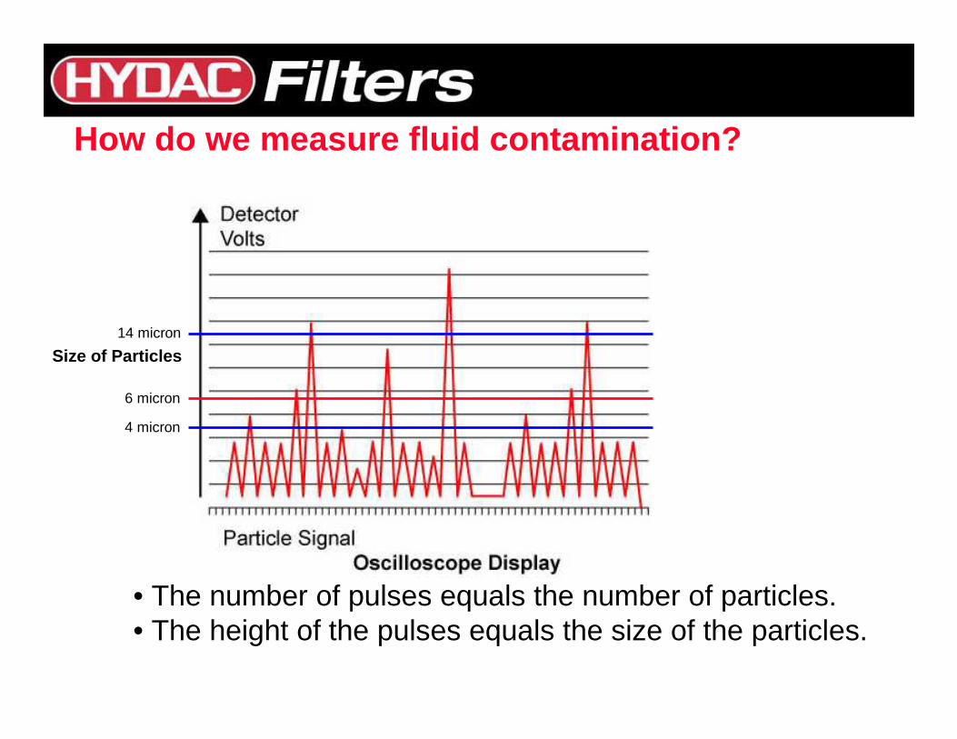
• The number of pulses equals the number of particles.• The height of the pulses equals the size of the particles.
Size of Particles
4 micron
6 micron
14 micron
How do we measure fluid contamination?
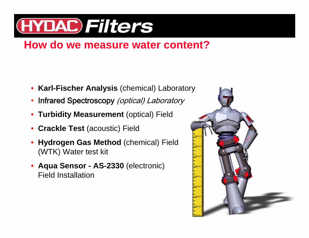
• Karl-Fischer Analysis (chemical) Laboratory
• Infrared SpectroscopyInfrared SpectroscopyInfrared SpectroscopyInfrared Spectroscopy (optical) Laboratory• Turbidity Measurement (optical) Field
• Crackle Test (acoustic) Field
• Hydrogen Gas Method (chemical) Field (WTK) Water test kit
• Aqua Sensor - AS-2330 (electronic)Field Installation
How do we measure water content?
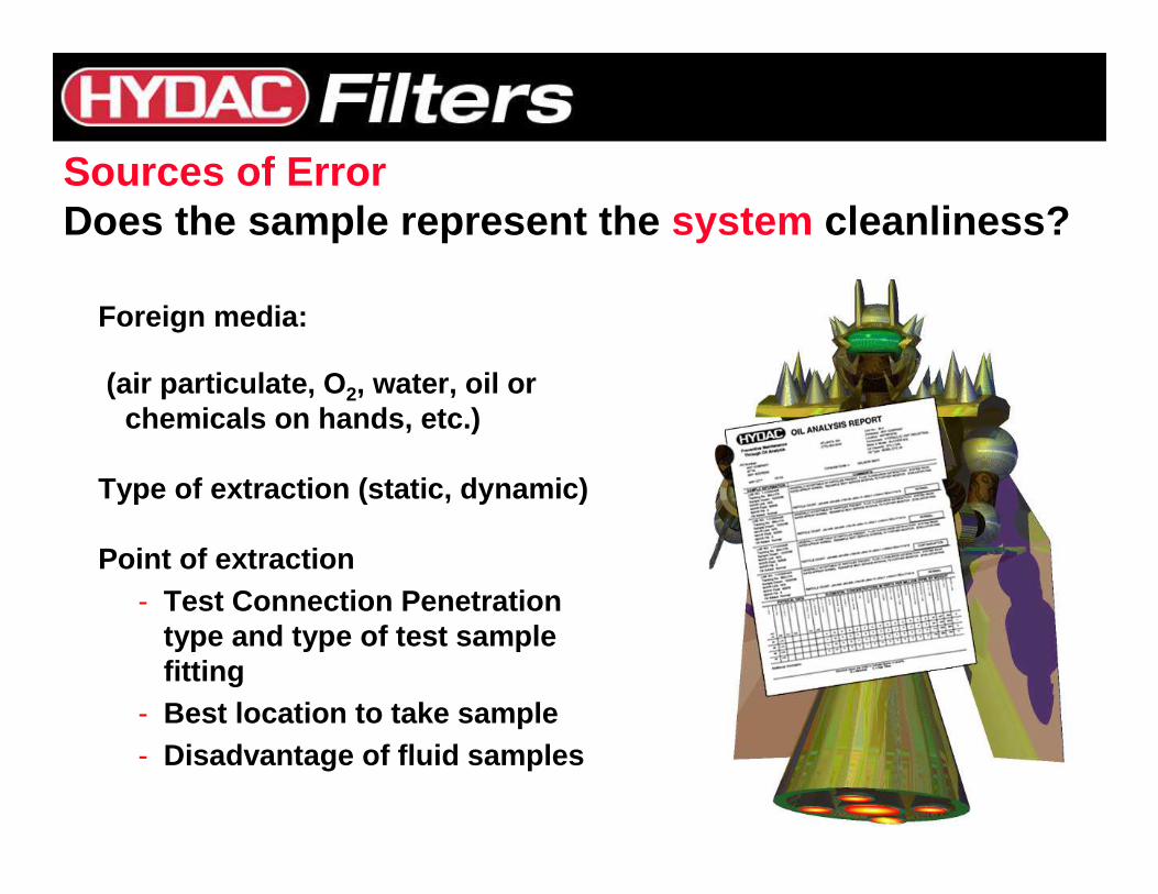
Foreign media:
(air particulate, O 2, water, oil or chemicals on hands, etc.)
Type of extraction (static, dynamic)
Point of extraction- Test Connection Penetration
type and type of test sample fitting
- Best location to take sample- Disadvantage of fluid samples
Sources of ErrorDoes the sample represent the system cleanliness?
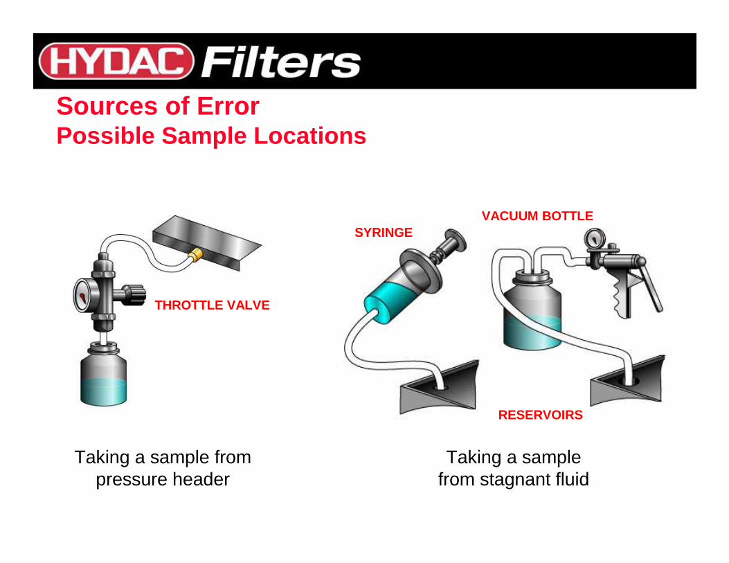
Taking a sample from pressure header
Taking a sample from stagnant fluid
SYRINGEVACUUM BOTTLE
RESERVOIRS
THROTTLE VALVE
Sources of ErrorPossible Sample Locations
Example:Reservoir Extraction with auxiliary pump
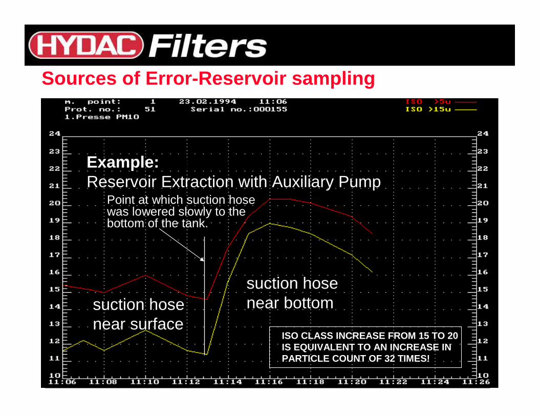
suction hosenear surface
suction hosenear bottom
Example:Reservoir Extraction with Auxiliary Pump
Point at which suction hosewas lowered slowly to the bottom of the tank.
ISO CLASS INCREASE FROM 15 TO 20IS EQUIVALENT TO AN INCREASE INPARTICLE COUNT OF 32 TIMES!
Sources of Error-Reservoir sampling
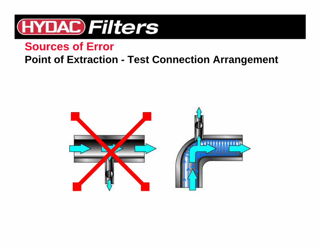
Sources of ErrorPoint of Extraction - Test Connection Arrangement
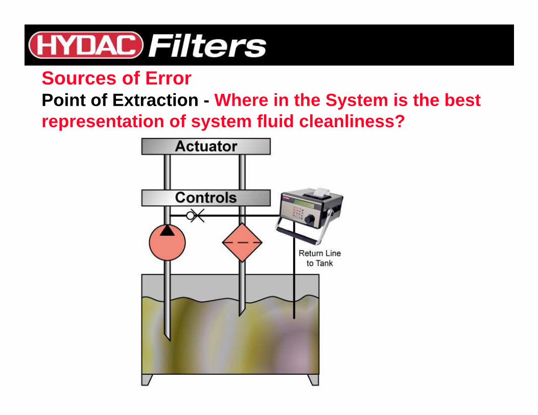
Sources of ErrorPoint of Extraction - Where in the System is the best representation of system fluid cleanliness?
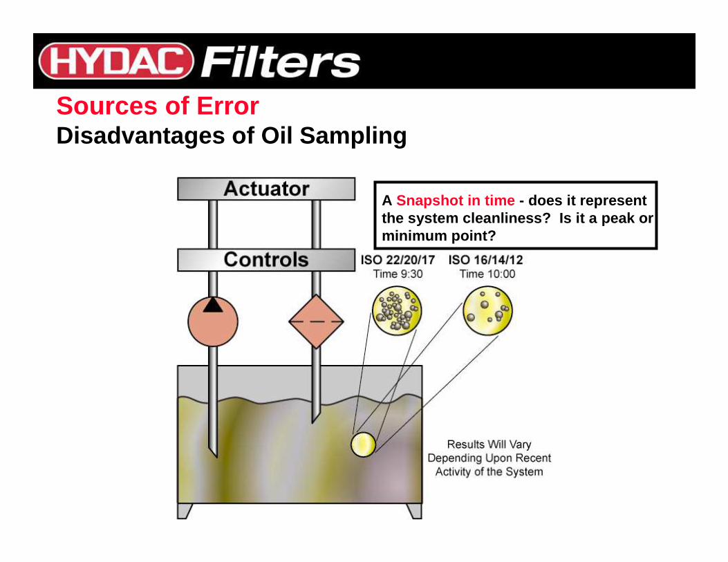
A Snapshot in time - does it representthe system cleanliness? Is it a peak orminimum point?
Sources of ErrorDisadvantages of Oil Sampling
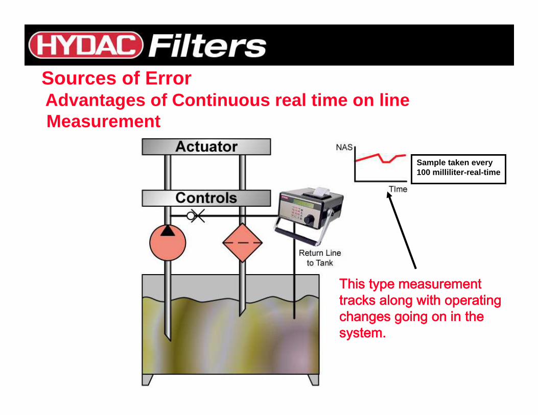
Sample taken every 100 milliliter-real-time
Sources of ErrorAdvantages of Continuous real time on line Measurement
This type measurementThis type measurementThis type measurementThis type measurementtracks along with operating tracks along with operating tracks along with operating tracks along with operating changes going on in the changes going on in the changes going on in the changes going on in the system.system.system.system.
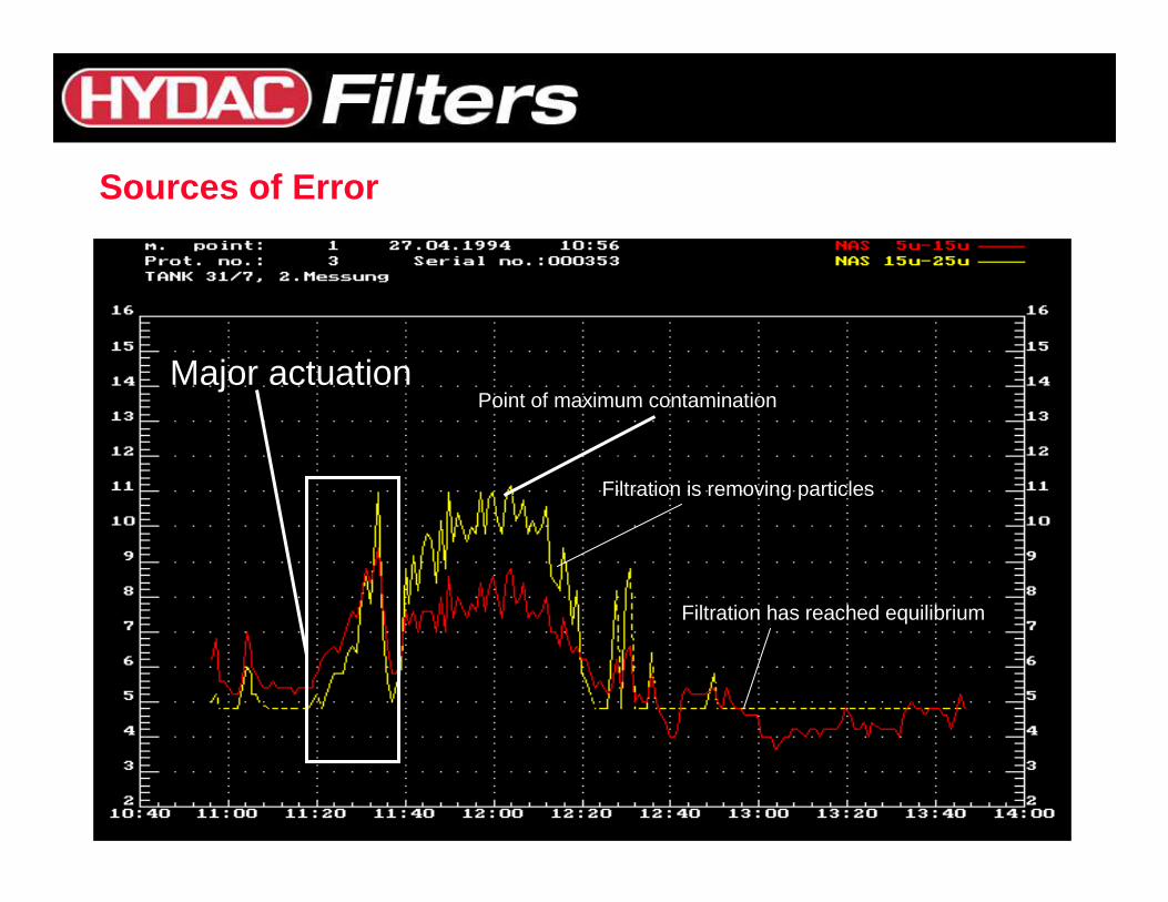
Sources of Error
Major actuationPoint of maximum contamination
Filtration is removing particles
Filtration has reached equilibrium
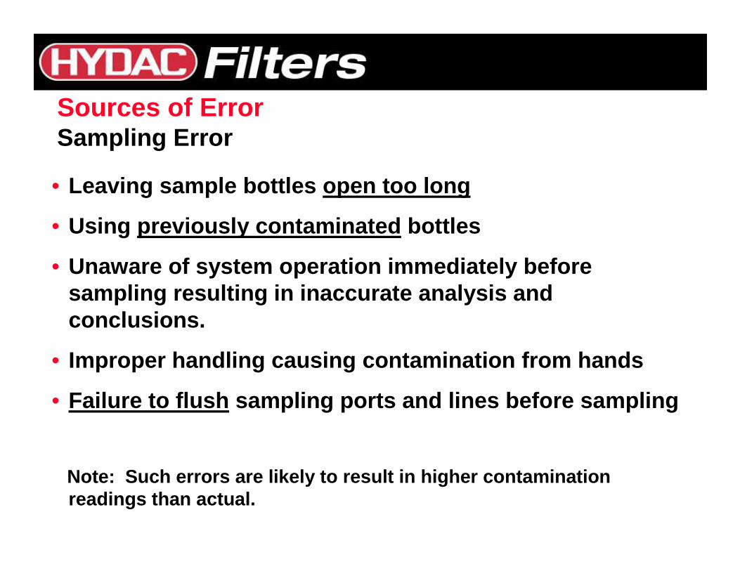
• Leaving sample bottles open too long
• Using previously contaminated bottles
• Unaware of system operation immediately before sampling resulting in inaccurate analysis and conclusions.
• Improper handling causing contamination from hands
• Failure to flush sampling ports and lines before sampling
Note: Such errors are likely to result in higher con tamination readings than actual.
Sources of ErrorSampling Error
Element TechnologyElement Technology
To assure maximum component life , fluid life and superior system and equipment operation?
CONTAMINANT LEVEL POPULATIONSMUST BE REDUCED TO LEVELS
REQUIRED BY CRITICAL SYSTEM COMPONENTS
HOW ?Through Proper Filtering, Monitoring,
Analysis, and Control
What Can Be Done?
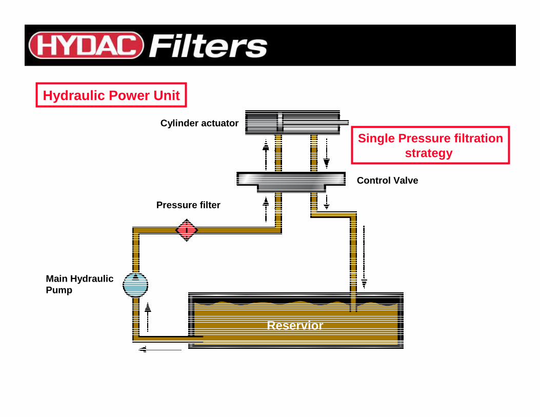
Hydraulic Power Unit
Cylinder actuator
Control Valve
Pressure filter
Main Hydraulic Pump
Reservior
Single Pressure filtrationstrategy
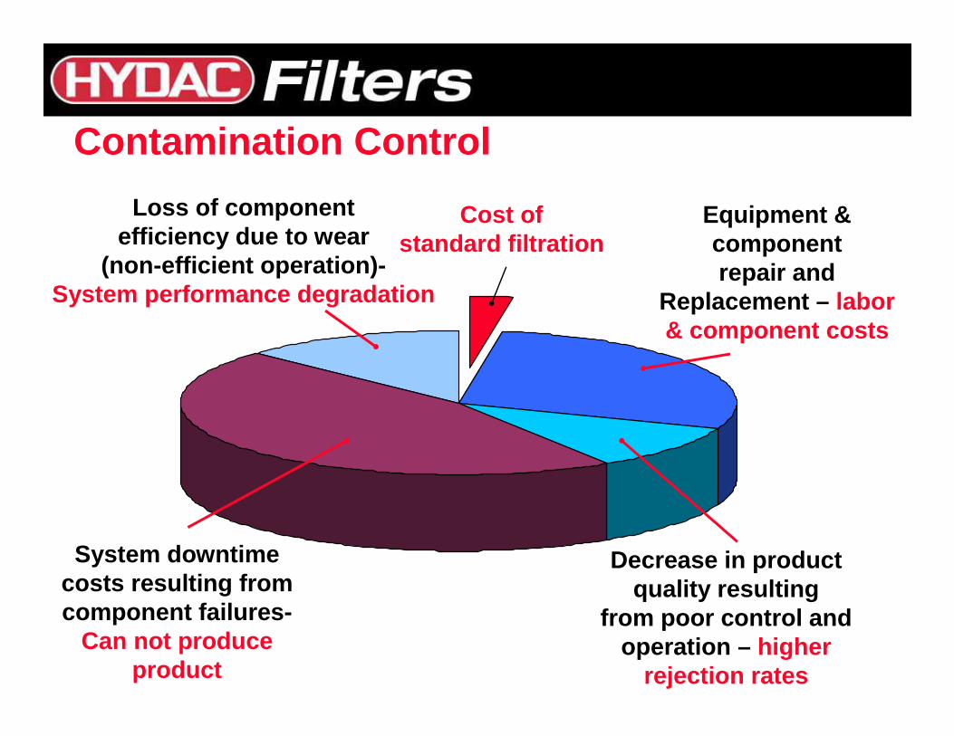
Cost ofstandard filtration
Loss of componentefficiency due to wear
(non-efficient operation)-System performance degradation
System downtime costs resulting fromcomponent failures-
Can not produce product
Decrease in product quality resulting
from poor control and operation – higher
rejection rates
Equipment &component repair and
Replacement – labor & component costs
Contamination Control
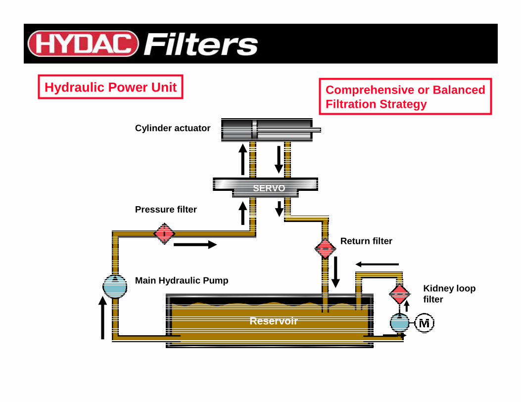
Pressure filter
Reservoir
Return filter
Kidney loopfilter
Main Hydraulic Pump
SERVO
Cylinder actuator
Hydraulic Power Unit Comprehensive or BalancedFiltration Strategy
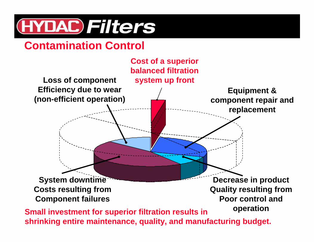
Cost of a superiorbalanced filtration system up front
System downtimeCosts resulting fromComponent failures
Decrease in productQuality resulting from
Poor control and operation
Equipment & component repair and
replacement
Small investment for superior filtration results in shrinking entire maintenance, quality, and manufact uring budget.
Loss of componentEfficiency due to wear
(non-efficient operation)
Contamination Control
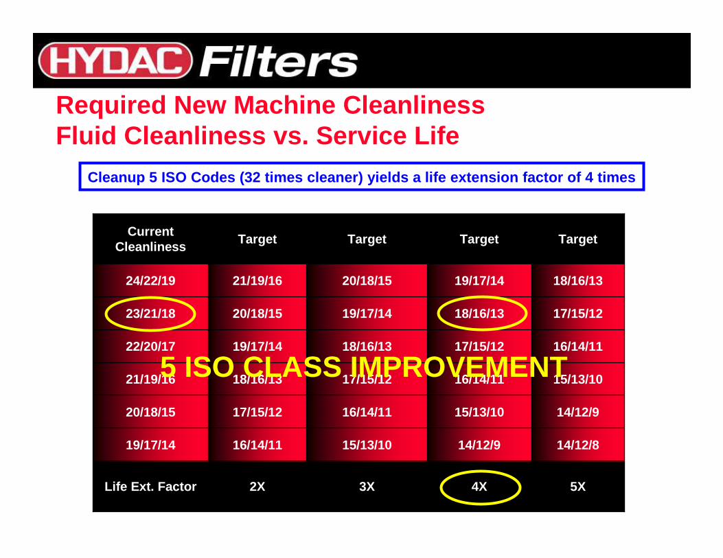
5X4X3X2XLife Ext. Factor
14/12/814/12/915/13/1016/14/1119/17/14
14/12/915/13/1016/14/1117/15/1220/18/15
15/13/1016/14/1117/15/1218/16/1321/19/16
16/14/1117/15/1218/16/1319/17/1422/20/17
17/15/1218/16/1319/17/1420/18/1523/21/18
18/16/1319/17/1420/18/1521/19/1624/22/19
TargetTargetTargetTargetCurrent
Cleanliness
Required New Machine CleanlinessFluid Cleanliness vs. Service Life
Cleanup 5 ISO Codes (32 times cleaner) yields a lif e extension factor of 4 times
5 ISO CLASS IMPROVEMENT
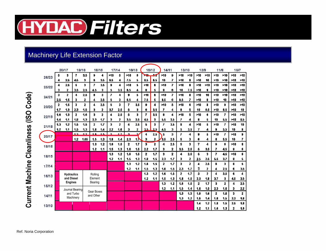
Machinery Life Extension Factor Machinery Life Extension Factor
Cu
rren
t M
ach
ine
Cle
anlin
ess
(IS
O C
od
e)
Hydraulics
and Diesel
Engines
Rolling
Element
Bearing
Journal Bearing
and Turbo
Machinery
Gear Boxes
and Other
Ref. Noria Corporation
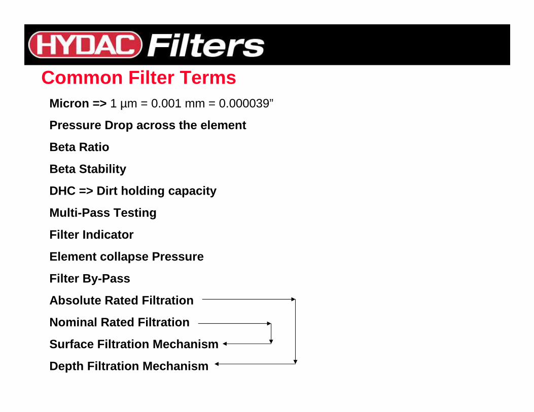
Common Filter TermsMicron => 1 µm = 0.001 mm = 0.000039”
Pressure Drop across the element
Beta Ratio
Beta Stability
DHC => Dirt holding capacity
Multi-Pass Testing
Filter Indicator
Element collapse Pressure
Filter By-Pass
Absolute Rated Filtration
Nominal Rated Filtration
Surface Filtration Mechanism
Depth Filtration Mechanism
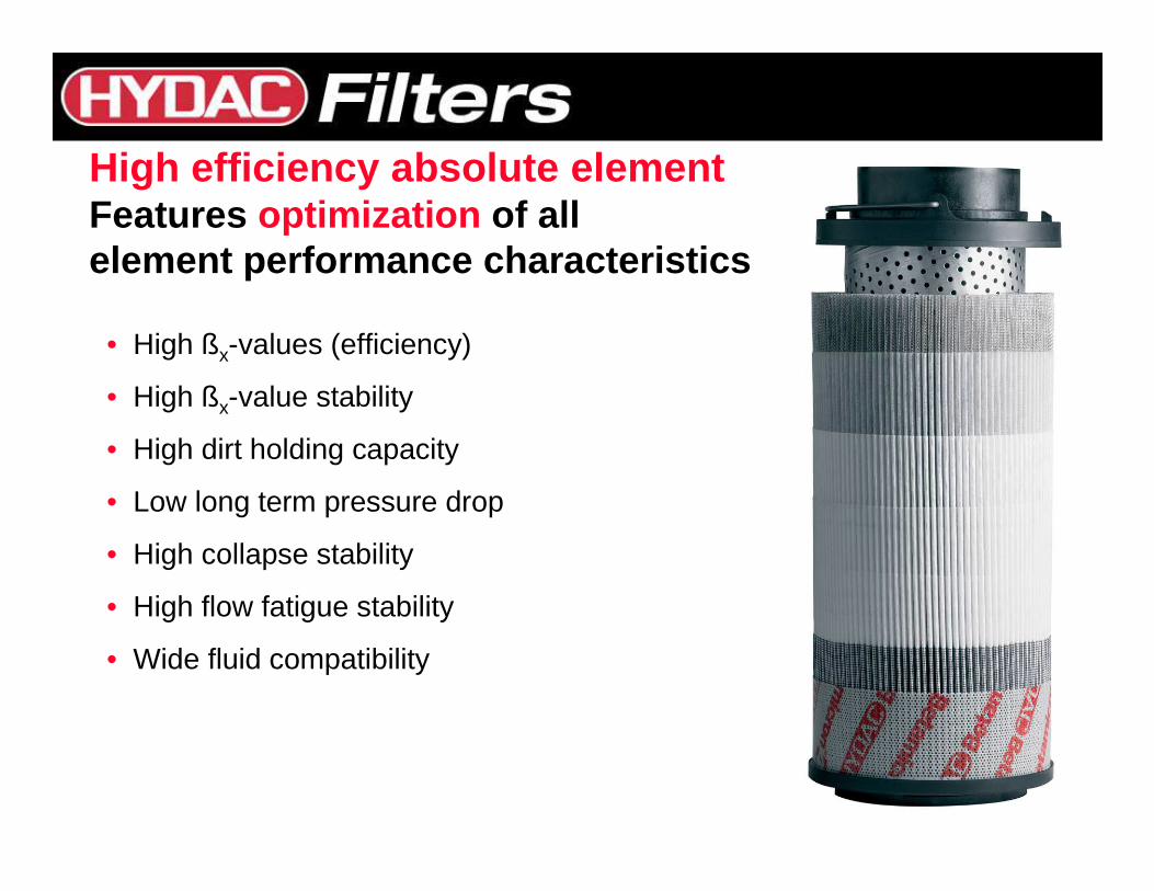
High efficiency absolute elementFeatures optimization of allelement performance characteristics
• High ßx-values (efficiency)
• High ßx-value stability
• High dirt holding capacity
• Low long term pressure drop
• High collapse stability
• High flow fatigue stability
• Wide fluid compatibility
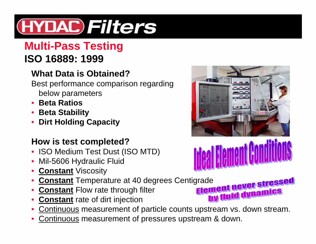
What Data is Obtained?Best performance comparison regarding
below parameters• Beta Ratios• Beta Stability• Dirt Holding Capacity
How is test completed?• ISO Medium Test Dust (ISO MTD)• Mil-5606 Hydraulic Fluid• Constant Viscosity • Constant Temperature at 40 degrees Centigrade• Constant Flow rate through filter• Constant rate of dirt injection• Continuous measurement of particle counts upstream vs. down stream. • Continuous measurement of pressures upstream & down.
Multi-Pass TestingISO 16889: 1999
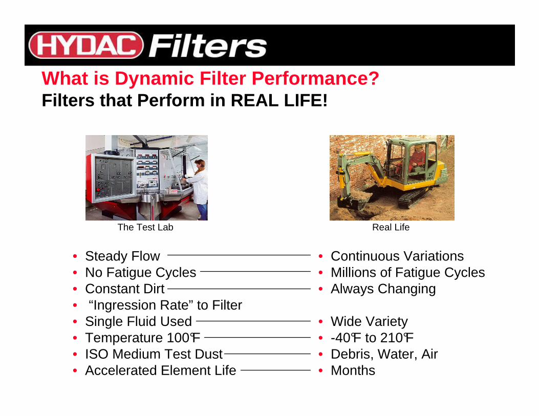
The Test Lab Real Life
• Steady Flow• No Fatigue Cycles• Constant Dirt • “Ingression Rate” to Filter• Single Fluid Used• Temperature 100°F• ISO Medium Test Dust• Accelerated Element Life
• Continuous Variations• Millions of Fatigue Cycles• Always Changing
• Wide Variety• -40°F to 210°F• Debris, Water, Air• Months
What is Dynamic Filter Performance?Filters that Perform in REAL LIFE!
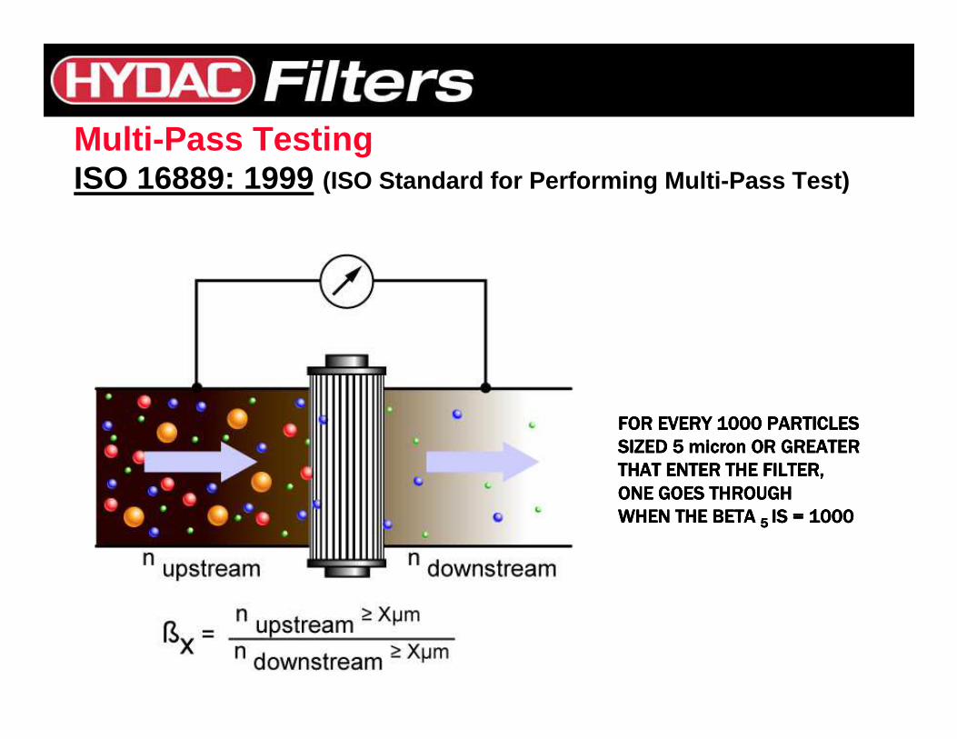
Multi-Pass TestingISO 16889: 1999 (ISO Standard for Performing Multi-Pass Test)
FOR EVERY 1000 PARTICLES FOR EVERY 1000 PARTICLES FOR EVERY 1000 PARTICLES FOR EVERY 1000 PARTICLES
SIZED 5 micron OR GREATER SIZED 5 micron OR GREATER SIZED 5 micron OR GREATER SIZED 5 micron OR GREATER
THAT ENTER THE FILTER,THAT ENTER THE FILTER,THAT ENTER THE FILTER,THAT ENTER THE FILTER,
ONE GOES THROUGH ONE GOES THROUGH ONE GOES THROUGH ONE GOES THROUGH
WHEN THE BETA WHEN THE BETA WHEN THE BETA WHEN THE BETA 5 5 5 5 IS = 1000IS = 1000IS = 1000IS = 1000
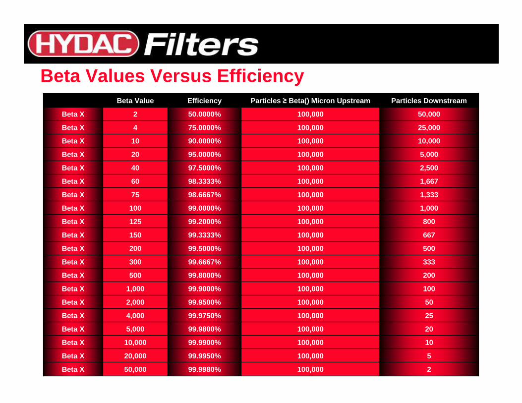
Beta Values Versus Efficiency
2100,00099.9980%50,000Beta X
5100,00099.9950%20,000Beta X
10100,00099.9900%10,000Beta X
20100,00099.9800%5,000Beta X
25100,00099.9750%4,000Beta X
50100,00099.9500%2,000Beta X
100100,00099.9000%1,000Beta X
200100,00099.8000%500Beta X
333100,00099.6667%300Beta X
500100,00099.5000%200Beta X
667100,00099.3333%150Beta X
800100,00099.2000%125Beta X
1,000100,00099.0000%100Beta X
1,333100,00098.6667%75Beta X
1,667100,00098.3333%60Beta X
2,500100,00097.5000%40Beta X
5,000100,00095.0000%20Beta X
10,000100,00090.0000%10Beta X
25,000100,00075.0000%4Beta X
50,000100,00050.0000%2Beta X
Particles DownstreamParticles ≥ Beta() Micron UpstreamEfficiencyBeta Value
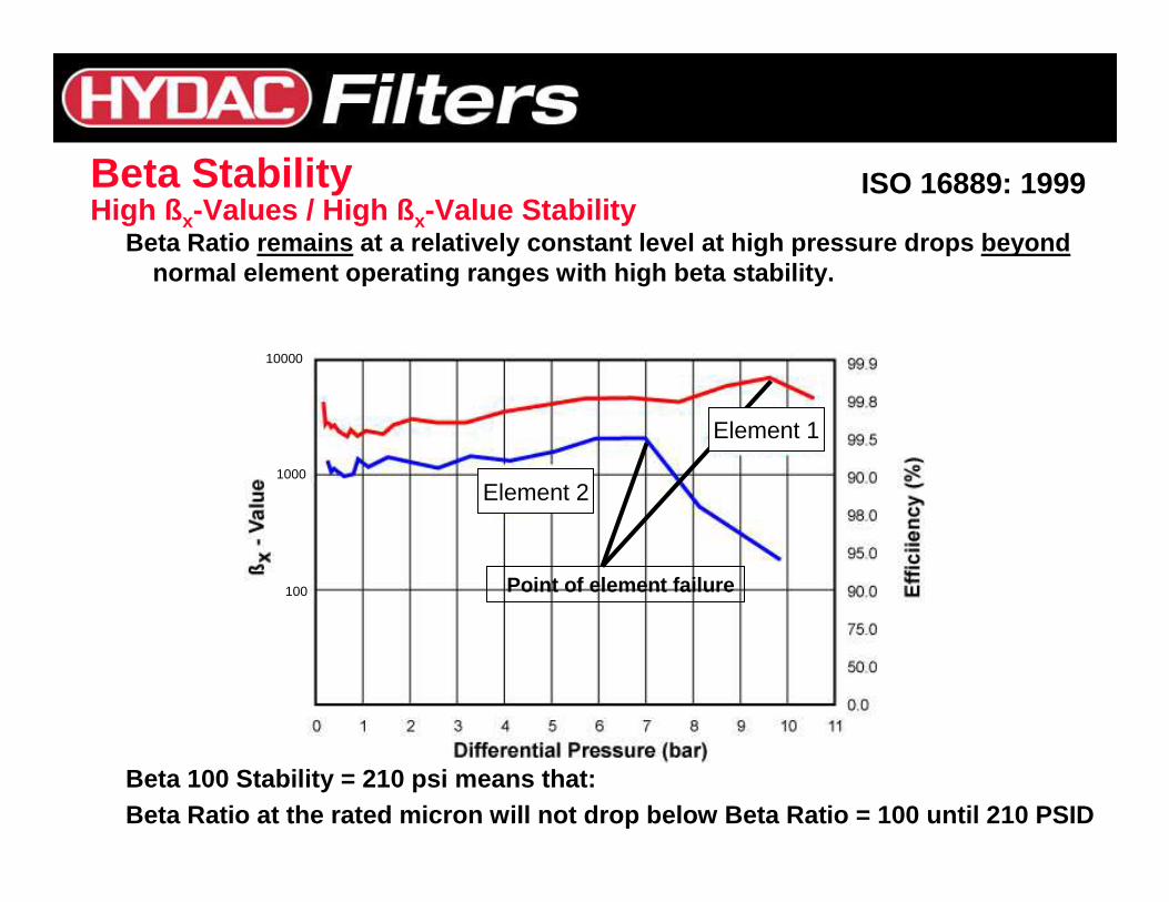
Beta Ratio remains at a relatively constant level at high pressure dro ps beyondnormal element operating ranges with high beta stab ility.
Beta 100 Stability = 210 psi means that:Beta Ratio at the rated micron will not drop below Beta Ratio = 100 until 210 PSID
Beta Stability ISO 16889: 1999
Point of element failure
High ß x-Values / High ß x-Value Stability
Element 1
Element 2
10000
1000
100
Poor Beta Stability Causes a loss of adequate protection from the point that Beta drops below manufacturermanufacturer ’’s published beta specifications published beta specification
before the end of element life.
• Significant loss of filter efficiency before the en d of element life
• Loss of equipment through loss of protection• Increased wear and component failures• Increased downtime• Decrease in Customer Satisfaction
• Decrease in downtimewhen indicator is utilized for change-out indication (Less Element Changes)
• Decrease in replacement element costs(longer lasting-utilizing full element capacity)
• Decrease in maintenance/labor costs
High Dirt Holding CapacityISO 16889: 1999
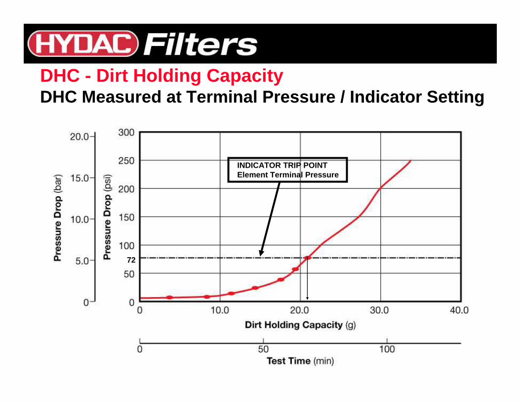
DHC - Dirt Holding CapacityDHC Measured at Terminal Pressure / Indicator Setti ng
72
INDICATOR TRIP POINTElement Terminal Pressure
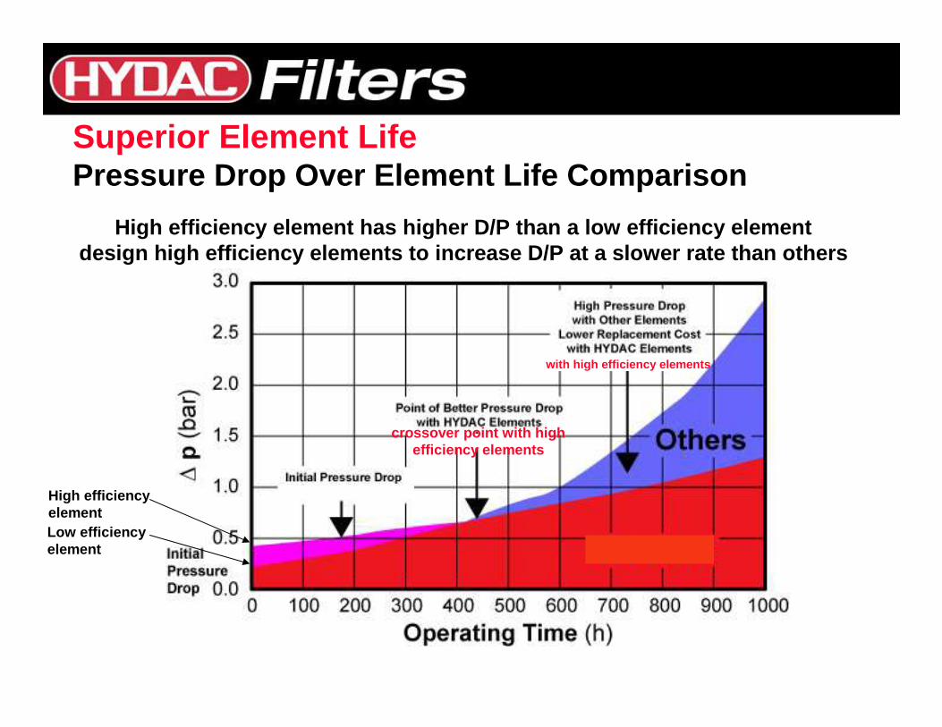
Superior Element LifePressure Drop Over Element Life Comparison
High efficiency element has higher D/P than a low e fficiency elementdesign high efficiency elements to increase D/P at a slower rate than others
with high efficiency elements
crossover point with highefficiency elements
High efficiencyelementLow efficiencyelement
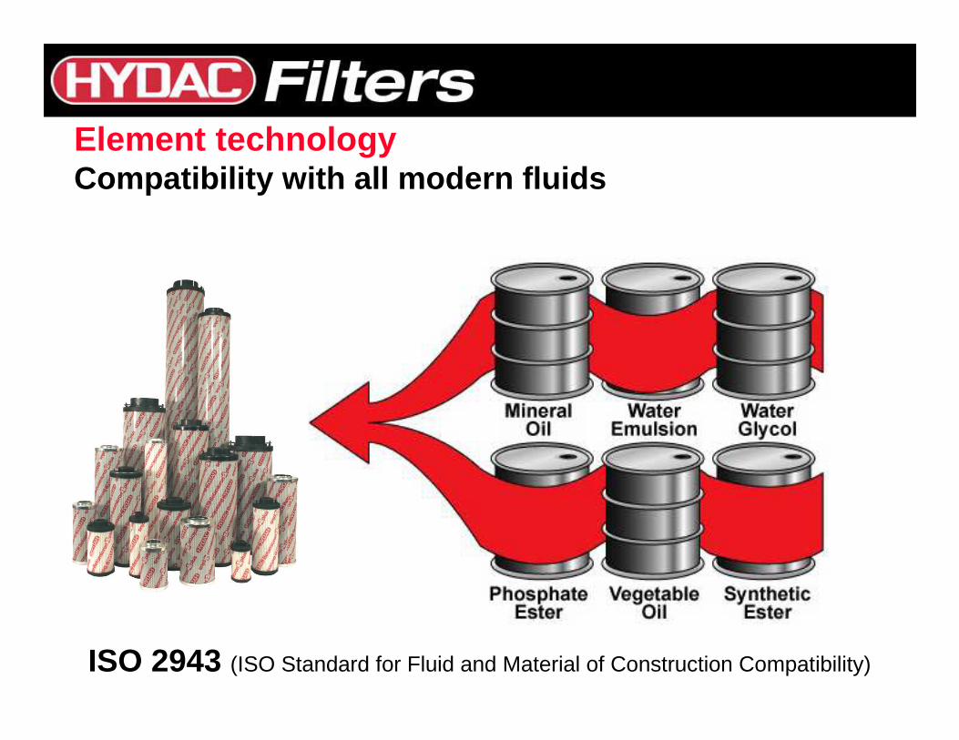
ISO 2943 (ISO Standard for Fluid and Material of Construction Compatibility)
Element technologyCompatibility with all modern fluids
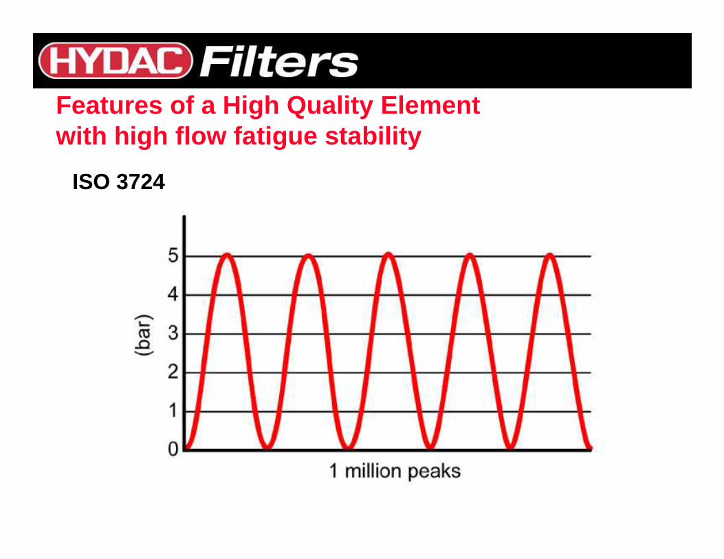
Features of a High Quality Element with high flow fatigue stability
ISO 3724
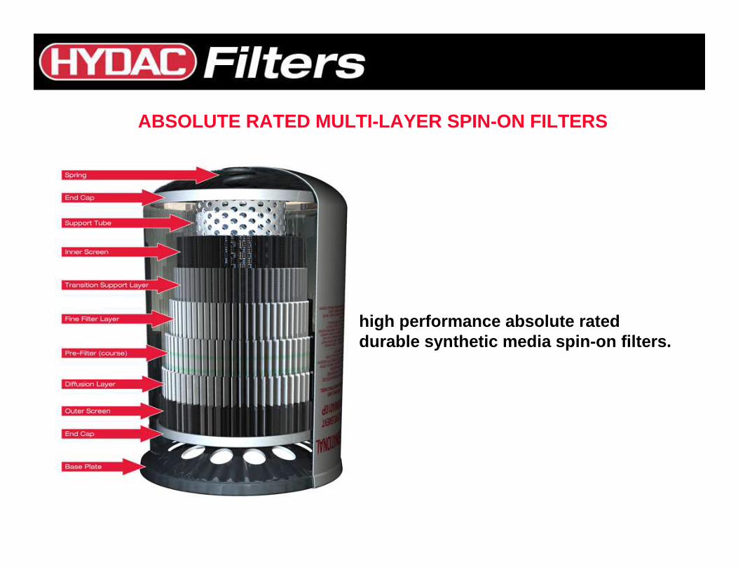
high performance absolute rated durable synthetic media spin-on filters.
ABSOLUTE RATED MULTI-LAYER SPIN-ON FILTERS
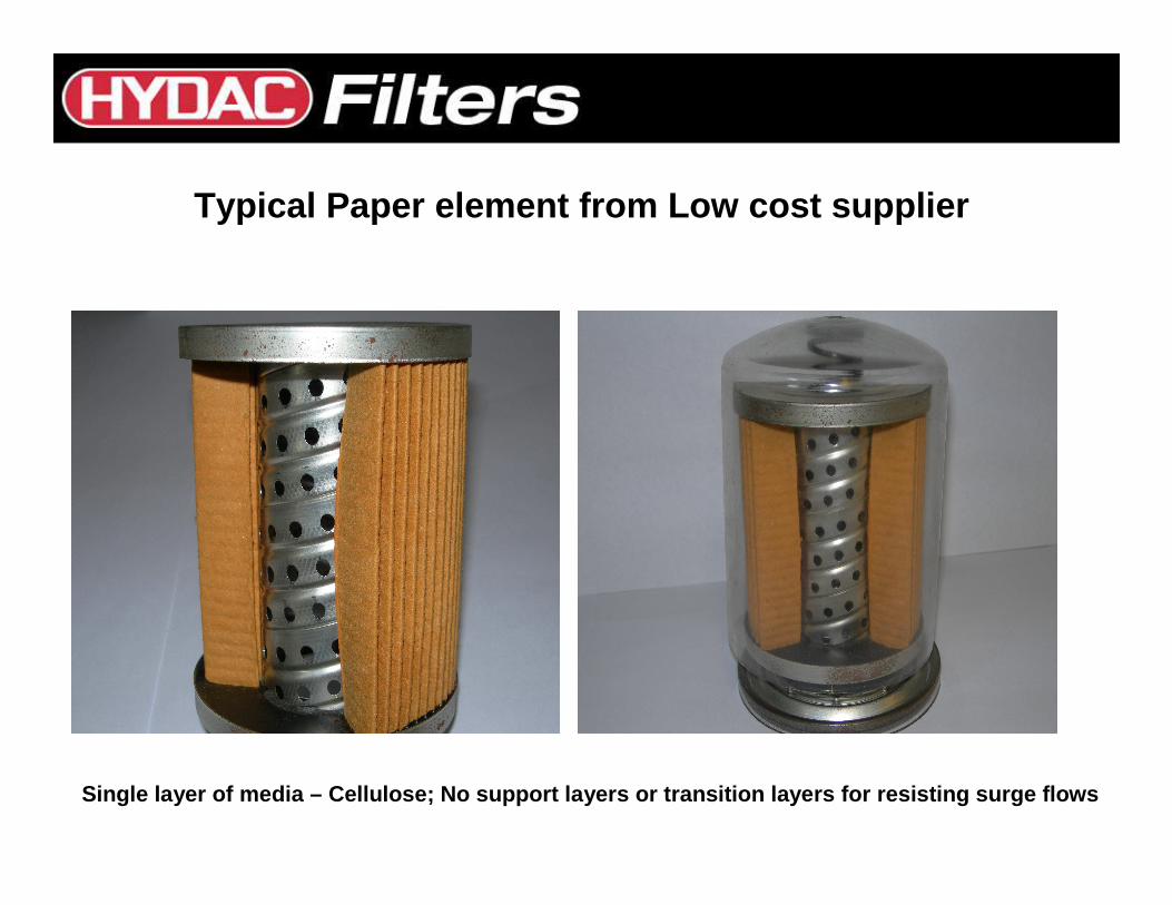
Typical Paper element from Low cost supplier
Single layer of media – Cellulose; No support layers or transition layers for resisting surge flows
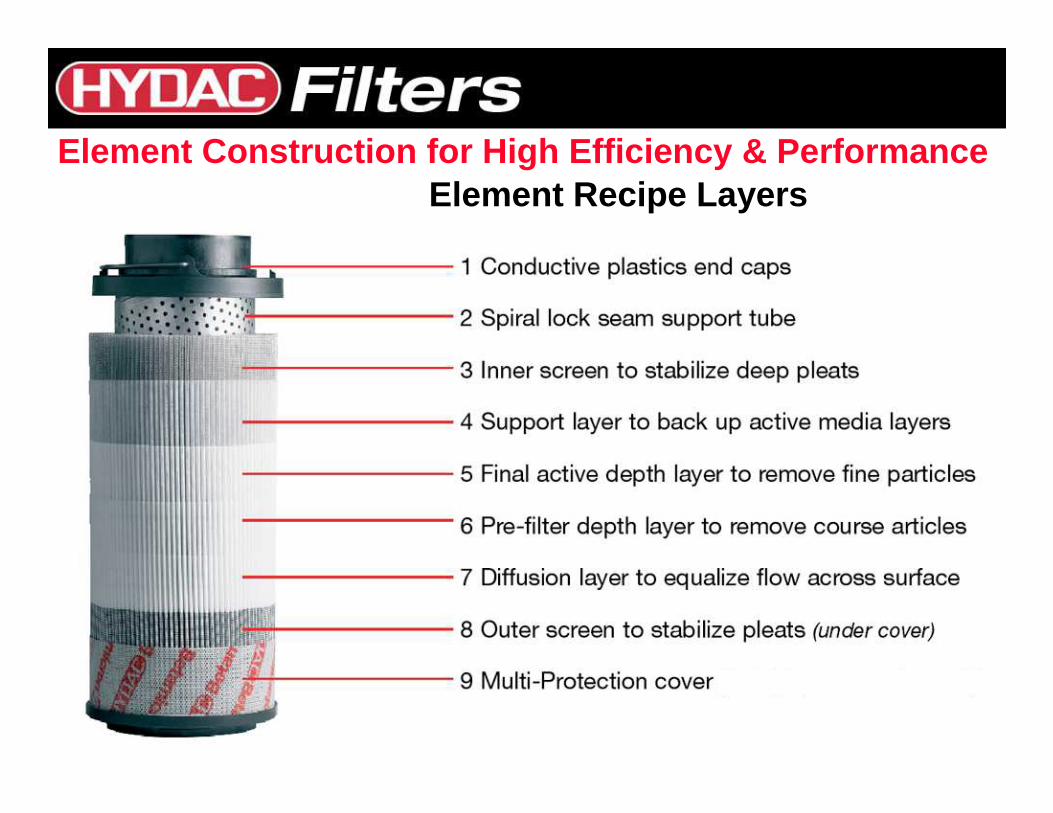
Element Recipe LayersElement Construction for High Efficiency & Performa nce
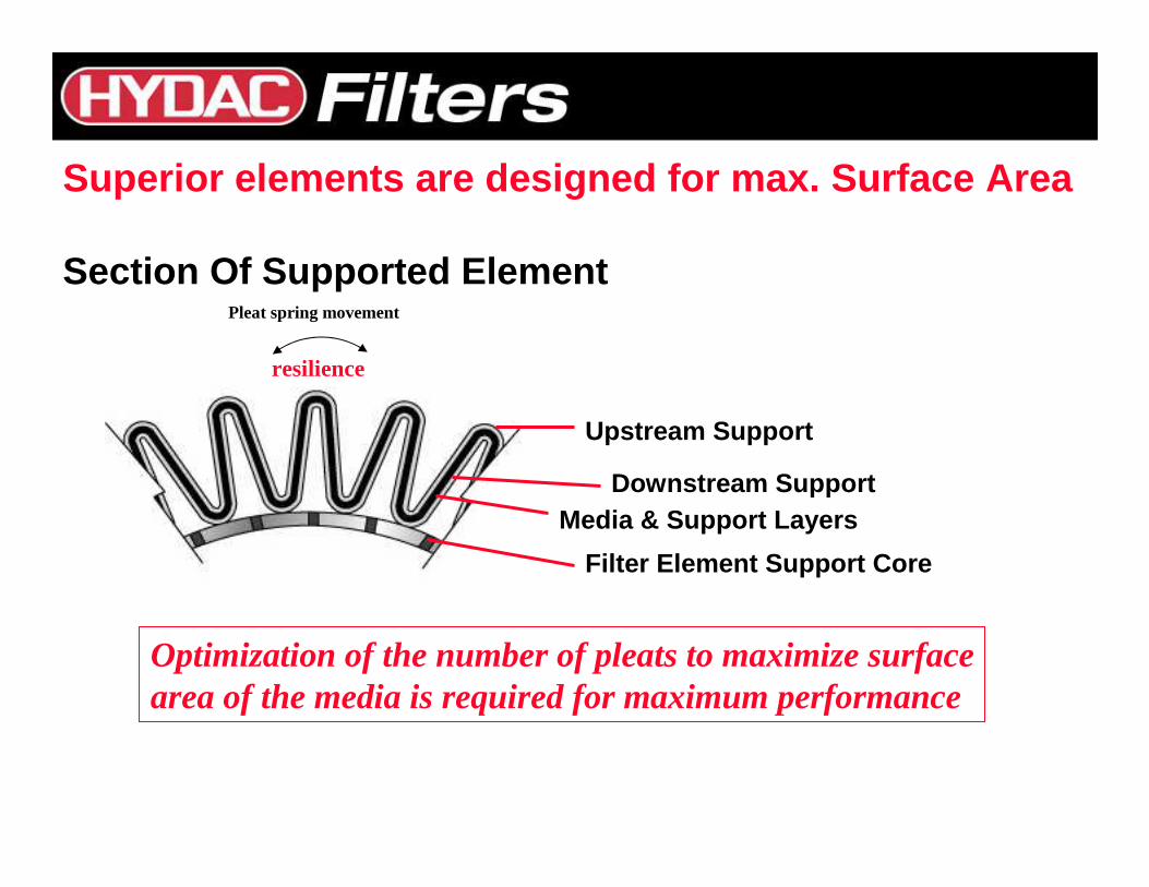
Filter Element Support Core
Downstream SupportMedia & Support Layers
Upstream Support
Superior elements are designed for max. Surface Are a
Section Of Supported ElementPleat spring movement
Optimization of the number of pleats to maximize surfacearea of the media is required for maximum performance
resilience
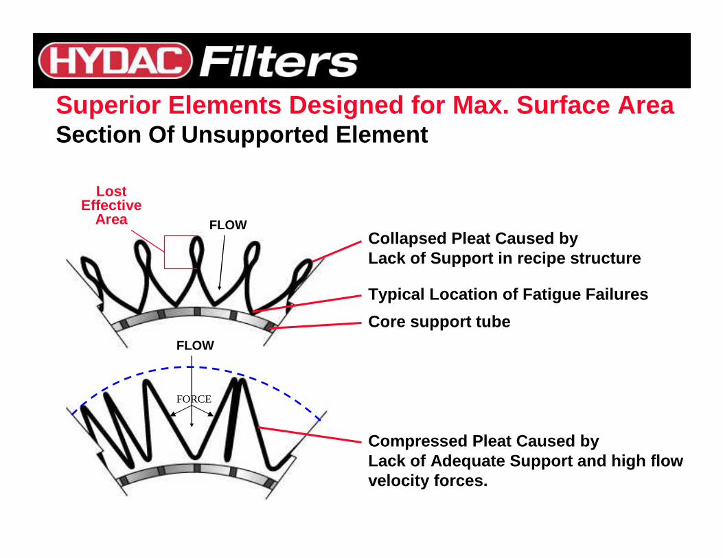
Core support tube
Typical Location of Fatigue Failures
Collapsed Pleat Caused by Lack of Support in recipe structure
Compressed Pleat Caused byLack of Adequate Support and high flow velocity forces.
LostEffective
Area
FLOW
FLOW
Superior Elements Designed for Max. Surface AreaSection Of Unsupported Element
FORCE
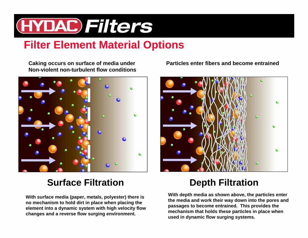
Surface Filtration Depth FiltrationWith surface media (paper, metals, polyester) there isno mechanism to hold dirt in place when placing the element into a dynamic system with high velocity fl owchanges and a reverse flow surging environment.
With depth media as shown above, the particles ente rthe media and work their way down into the pores an dpassages to become entrained. This provides the mechanism that holds these particles in place when used in dynamic flow surging systems.
Caking occurs on surface of media under Non-violent non-turbulent flow conditions
Particles enter fibers and become entrained
Filter Element Material Options
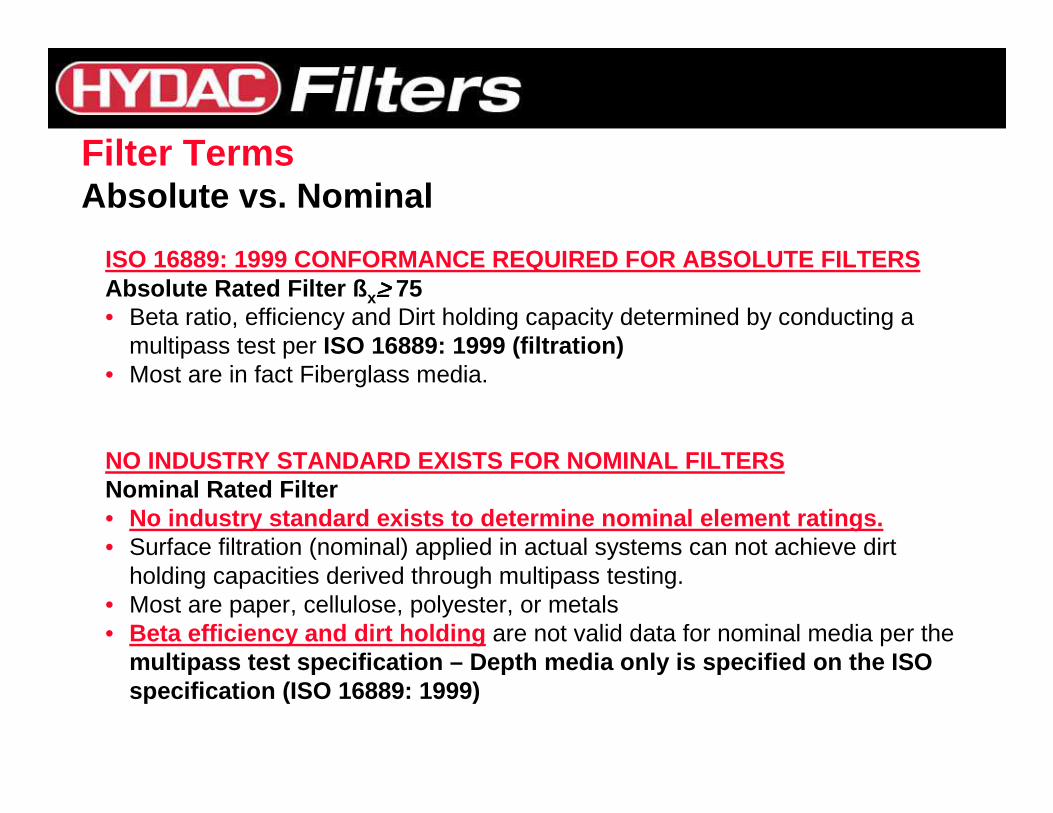
Filter TermsAbsolute vs. Nominal
ISO 16889: 1999 CONFORMANCE REQUIRED FOR ABSOLUTE F ILTERSAbsolute Rated Filter ß x≥≥≥≥ 75• Beta ratio, efficiency and Dirt holding capacity determined by conducting a
multipass test per ISO 16889: 1999 (filtration)• Most are in fact Fiberglass media.
NO INDUSTRY STANDARD EXISTS FOR NOMINAL FILTERSNominal Rated Filter• No industry standard exists to determine nominal el ement ratings.• Surface filtration (nominal) applied in actual systems can not achieve dirt
holding capacities derived through multipass testing. • Most are paper, cellulose, polyester, or metals• Beta efficiency and dirt holding are not valid data for nominal media per the
multipass test specification – Depth media only is s pecified on the ISOspecification (ISO 16889: 1999)
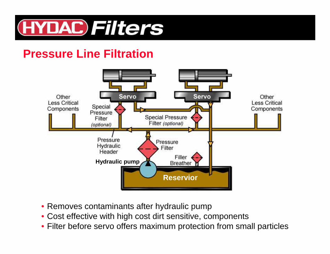
• Removes contaminants after hydraulic pump• Cost effective with high cost dirt sensitive, components• Filter before servo offers maximum protection from small particles
Pressure Line Filtration
Reservior
Hydraulic pump
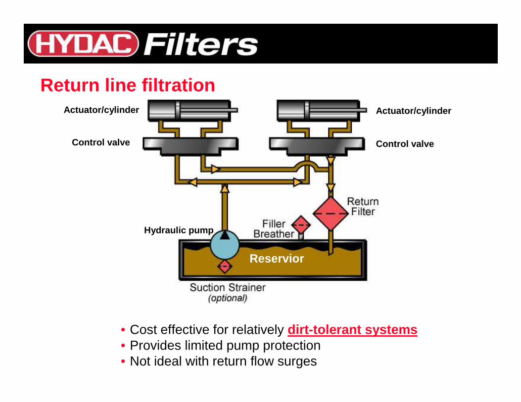
Return line filtration
• Cost effective for relatively dirt-tolerant systems• Provides limited pump protection• Not ideal with return flow surges
Reservior
Control valve Control valve
Actuator/cylinder Actuator/cylinder
Hydraulic pump
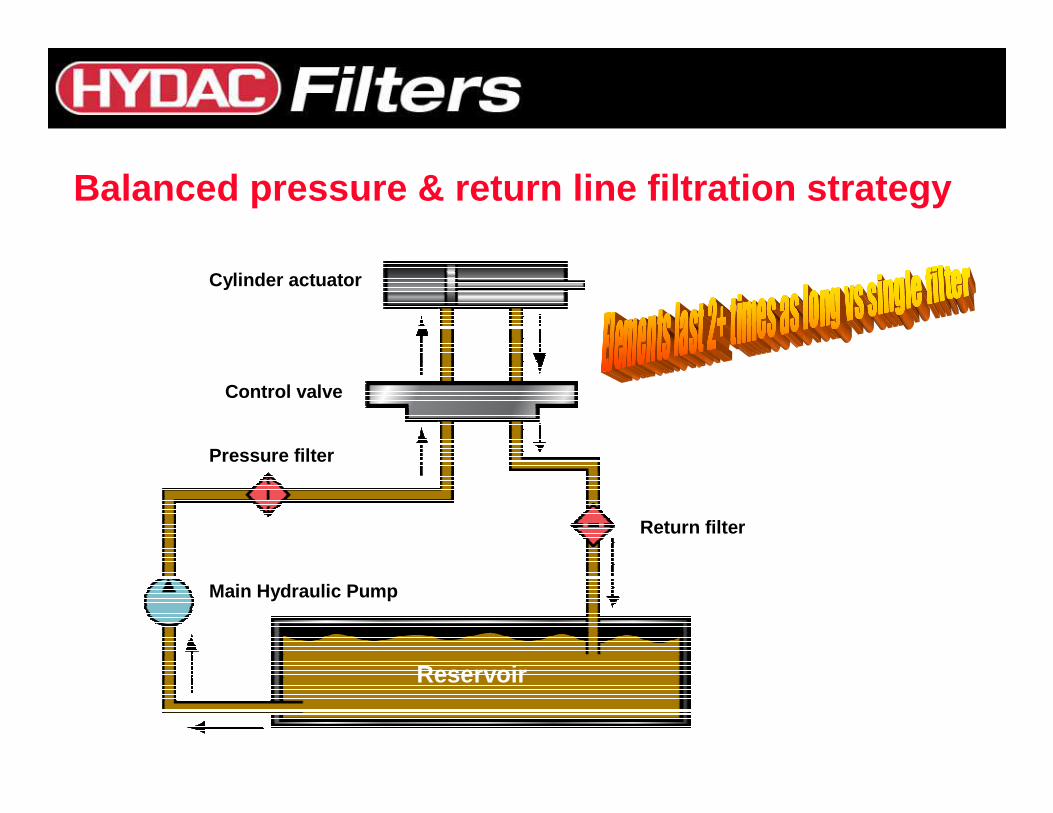
Balanced pressure & return line filtration strategy
Cylinder actuator
Pressure filter
Return filter
Reservoir
Main Hydraulic Pump
Control valve
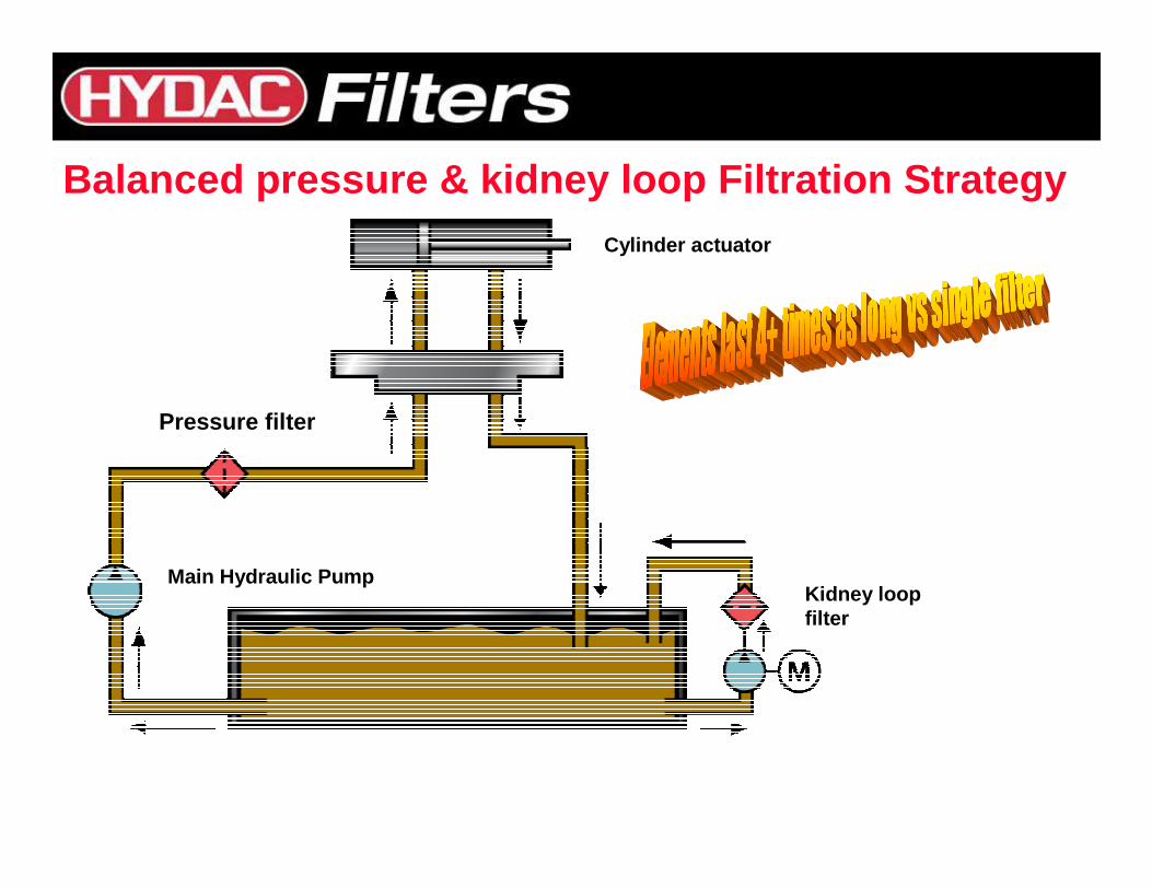
Balanced pressure & kidney loop Filtration Strategy
Reservoir
Pressure filter
SERVO
Cylinder actuator
Main Hydraulic PumpKidney loopfilter

Multiple Filters Provide• Maximum protection• Lowest contamination level• Extended element & hydraulic system life
Comprehensive Filtration
Off-Line Filter Provides• High efficient filtration• Continuous filtration• Fill port for filtering new oil
Reservior
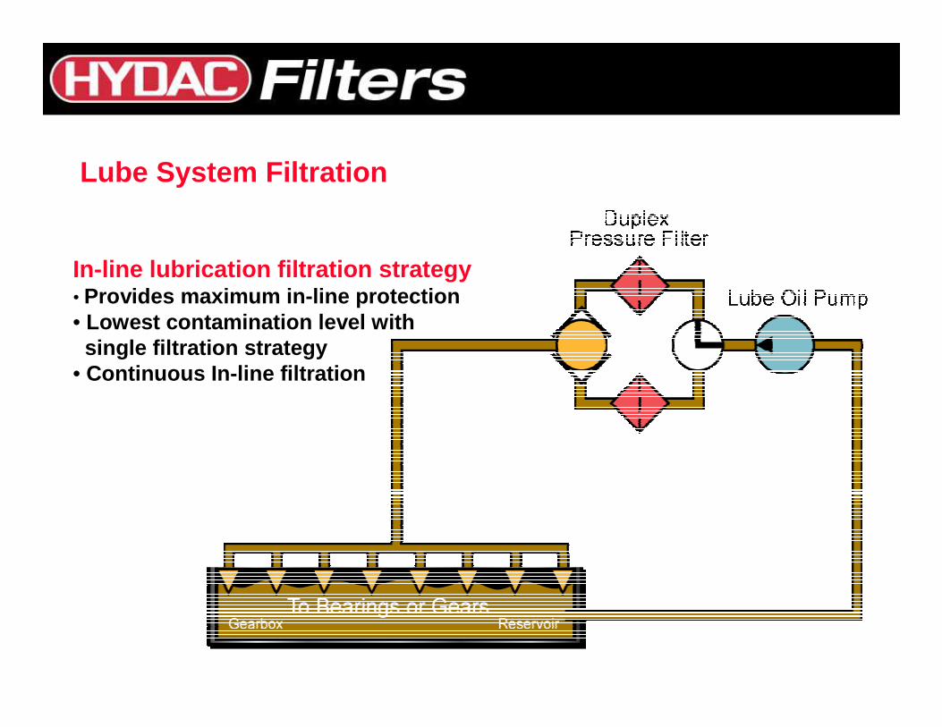
Lube System Filtration
In-line lubrication filtration strategy• Provides maximum in-line protection• Lowest contamination level with
single filtration strategy• Continuous In-line filtration
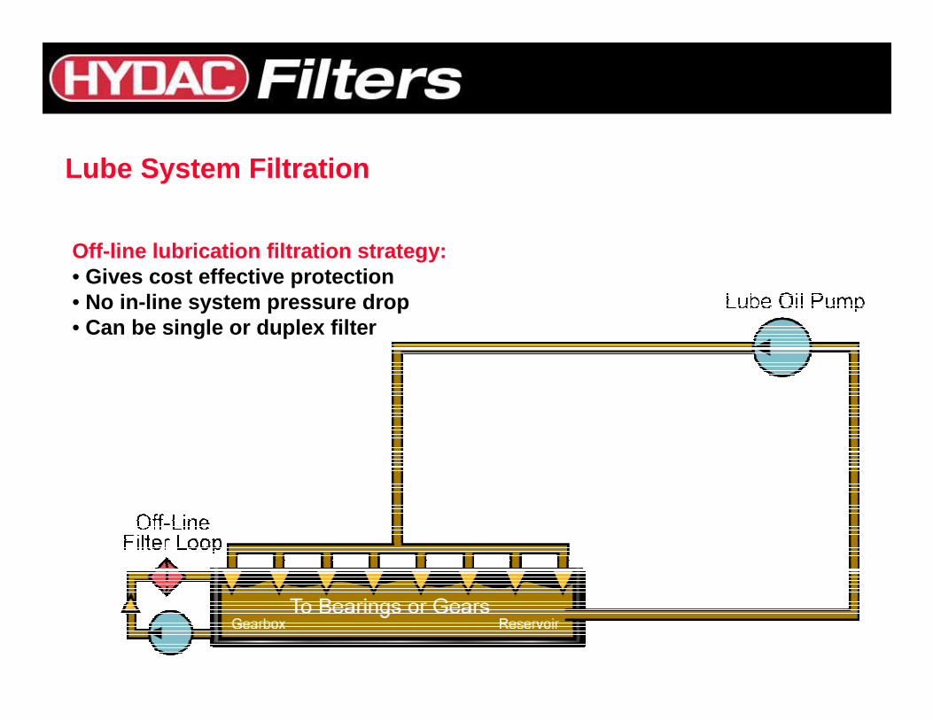
Lube System Filtration
Off-line lubrication filtration strategy:• Gives cost effective protection• No in-line system pressure drop• Can be single or duplex filter
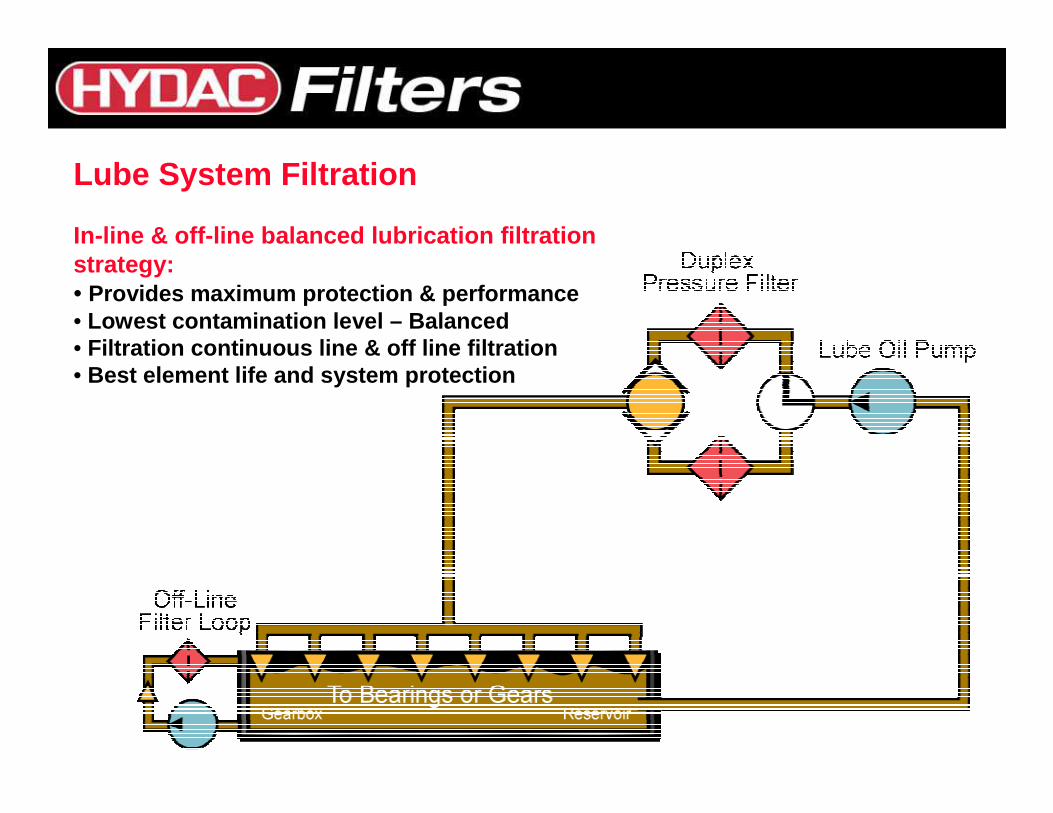
Lube System Filtration
In-line & off-line balanced lubrication filtration strategy:• Provides maximum protection & performance• Lowest contamination level – Balanced • Filtration continuous line & off line filtration• Best element life and system protection
FLUID HANDLING CONCEPTS AND CONSIDERATIONS
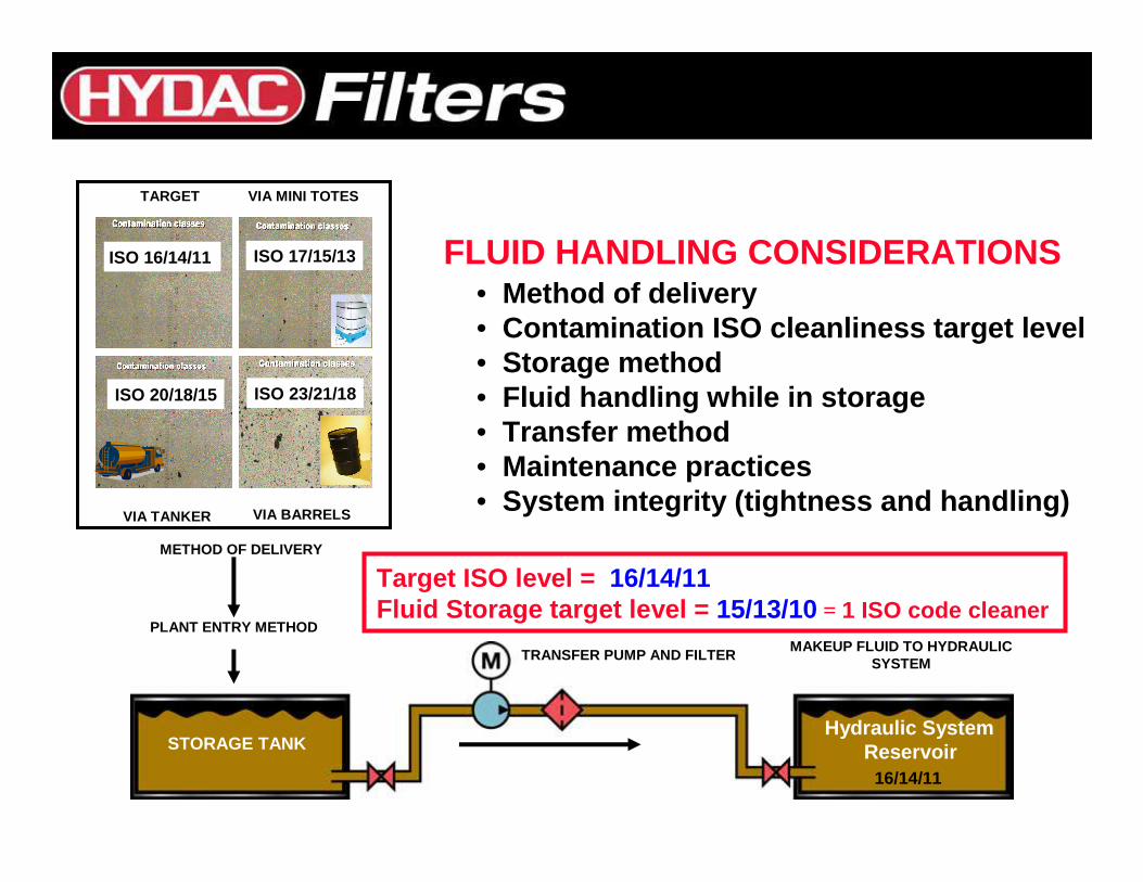
ISO 16/14/11 ISO 17/15/13
ISO 20/18/15 ISO 23/21/18
TARGET VIA MINI TOTES
VIA TANKER VIA BARRELS
PLANT ENTRY METHOD
TRANSFER PUMP AND FILTERMAKEUP FLUID TO HYDRAULIC
SYSTEM
FLUID HANDLING CONSIDERATIONS• Method of delivery• Contamination ISO cleanliness target level• Storage method• Fluid handling while in storage• Transfer method• Maintenance practices • System integrity (tightness and handling)
METHOD OF DELIVERY
STORAGE TANKHydraulic System
Reservoir
Target ISO level = 16/14/11Fluid Storage target level = 15/13/10 = 1 ISO code cleaner
16/14/11
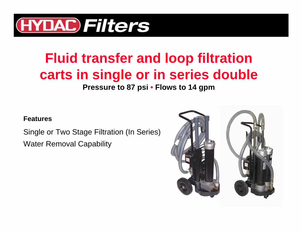
Fluid transfer and loop filtration carts in single or in series double
Pressure to 87 psi • Flows to 14 gpm
Features
Single or Two Stage Filtration (In Series)
Water Removal Capability
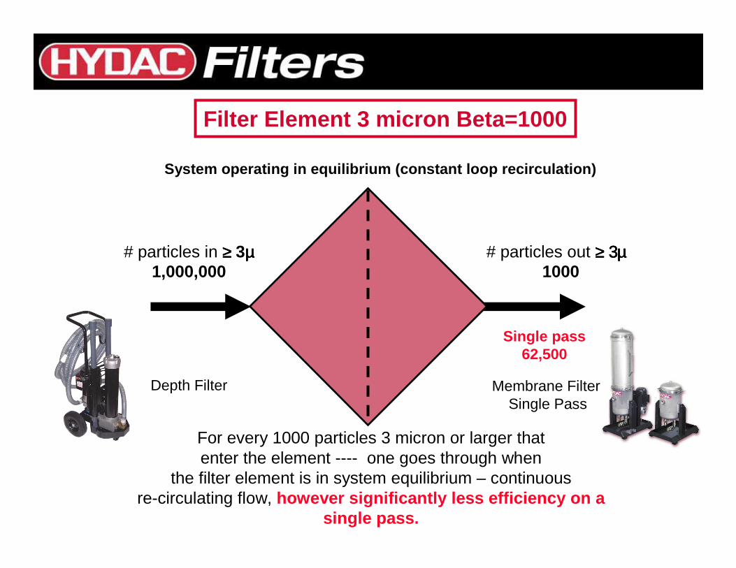
Filter Element 3 micron Beta=1000
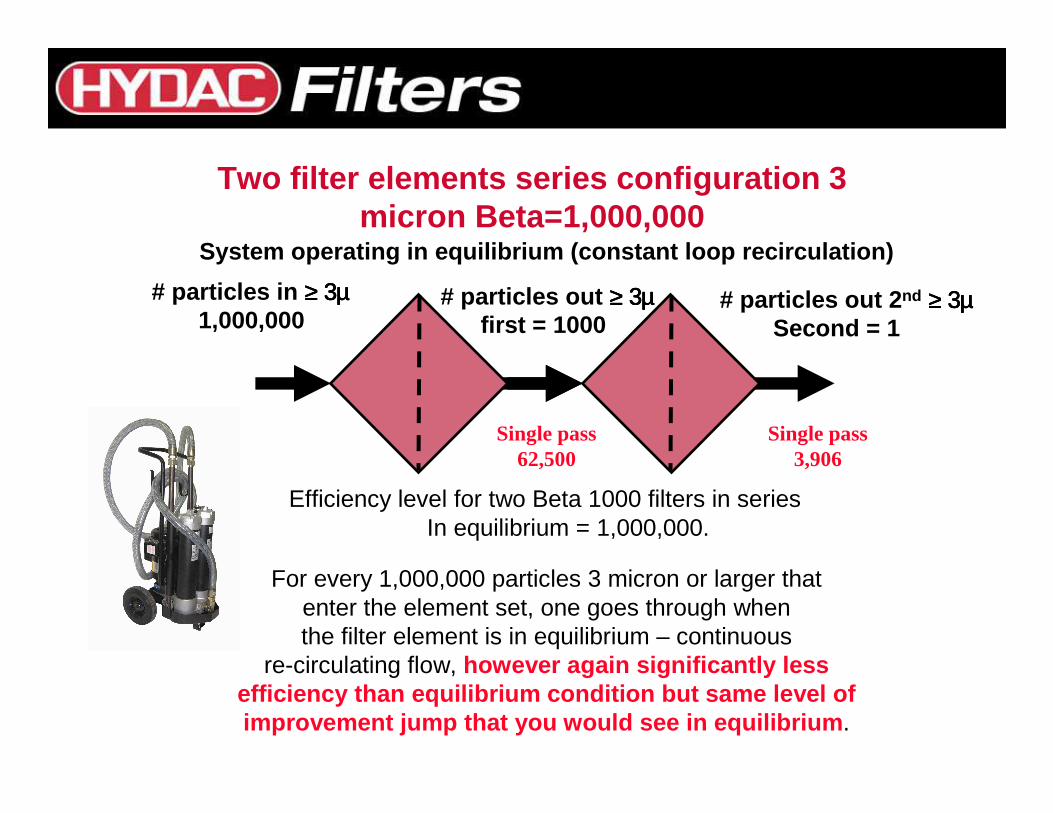
# particles in ≥≥≥≥ 3µµµµ1,000,000
# particles out ≥≥≥≥ 3µ3µ3µ3µ1000
For every 1000 particles 3 micron or larger thatenter the element ---- one goes through when
the filter element is in system equilibrium – continuous re-circulating flow, however significantly less efficiency on a
single pass.
Depth Filter Membrane FilterSingle Pass
Single pass62,500
System operating in equilibrium (constant loop reci rculation)
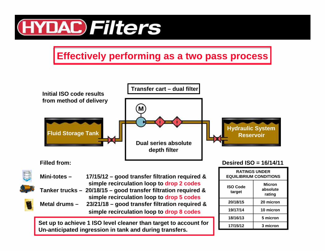
Fluid Storage TankHydraulic System
ReservoirDual series absolute
depth filter
Desired ISO = 16/14/11
Transfer cart – dual filter
Filled from:
Mini-totes – 17/15/12 – good transfer filtration requ ired &simple recirculation loop to drop 2 codes
Tanker trucks – 20/18/15 – good transfer filtration r equired &simple recirculation loop to drop 5 codes
Metal drums – 23/21/18 – good transfer filtration req uired &simple recirculation loop to drop 8 codes
Initial ISO code resultsfrom method of delivery
3 micron17/15/12
5 micron18/16/13
10 micron19/17/14
20 micron20/18/15
Micron absolute
rating
ISO Code target
RATINGS UNDER EQUILIBRIUM CONDITIONS
Effectively performing as a two pass process
Set up to achieve 1 ISO level cleaner than target t o account forUn-anticipated ingression in tank and during transf ers.
# particles in ≥≥≥≥ 3µ3µ3µ3µ1,000,000
# particles out 2 nd ≥≥≥≥ 3µ3µ3µ3µSecond = 1
For every 1,000,000 particles 3 micron or larger thatenter the element set, one goes through when the filter element is in equilibrium – continuous
re-circulating flow, however again significantly less efficiency than equilibrium condition but same leve l of improvement jump that you would see in equilibrium .
# particles out ≥≥≥≥ 3µ3µ3µ3µfirst = 1000
Efficiency level for two Beta 1000 filters in seriesIn equilibrium = 1,000,000.
Two filter elements series configuration 3 micron Beta=1,000,000
Single pass62,500
Single pass3,906
System operating in equilibrium (constant loop reci rculation)
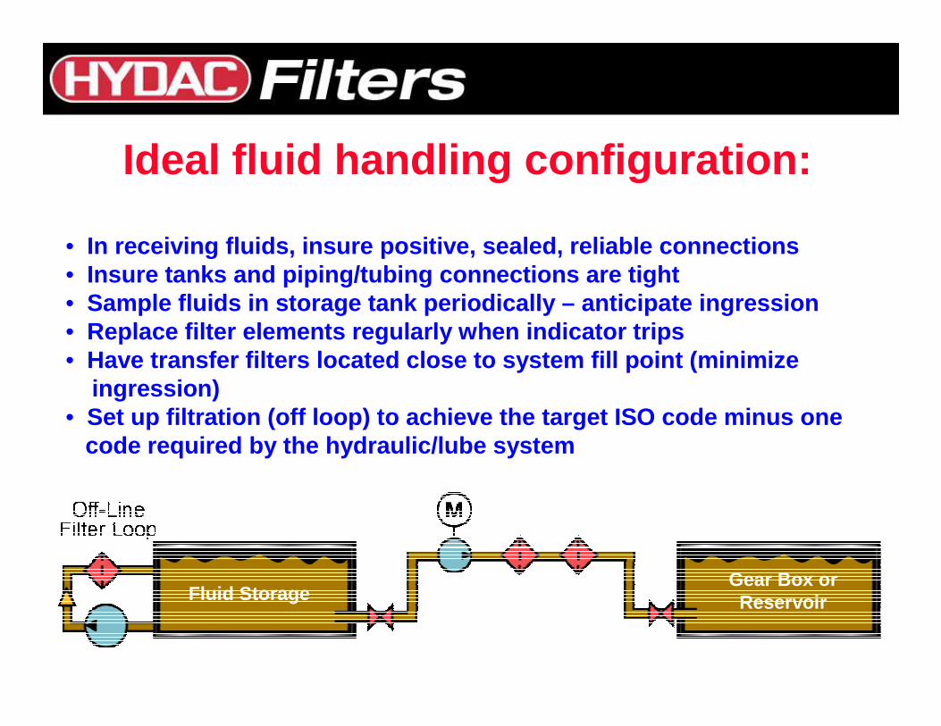
Ideal fluid handling configuration:
• In receiving fluids, insure positive, sealed, relia ble connections• Insure tanks and piping/tubing connections are tigh t• Sample fluids in storage tank periodically – anticip ate ingression• Replace filter elements regularly when indicator tr ips• Have transfer filters located close to system fill point (minimize
ingression)• Set up filtration (off loop) to achieve the target ISO code minus one
code required by the hydraulic/lube system
Fluid Storage Tank Hydraulic System Reservoir
Fluid StorageGear Box orReservoir
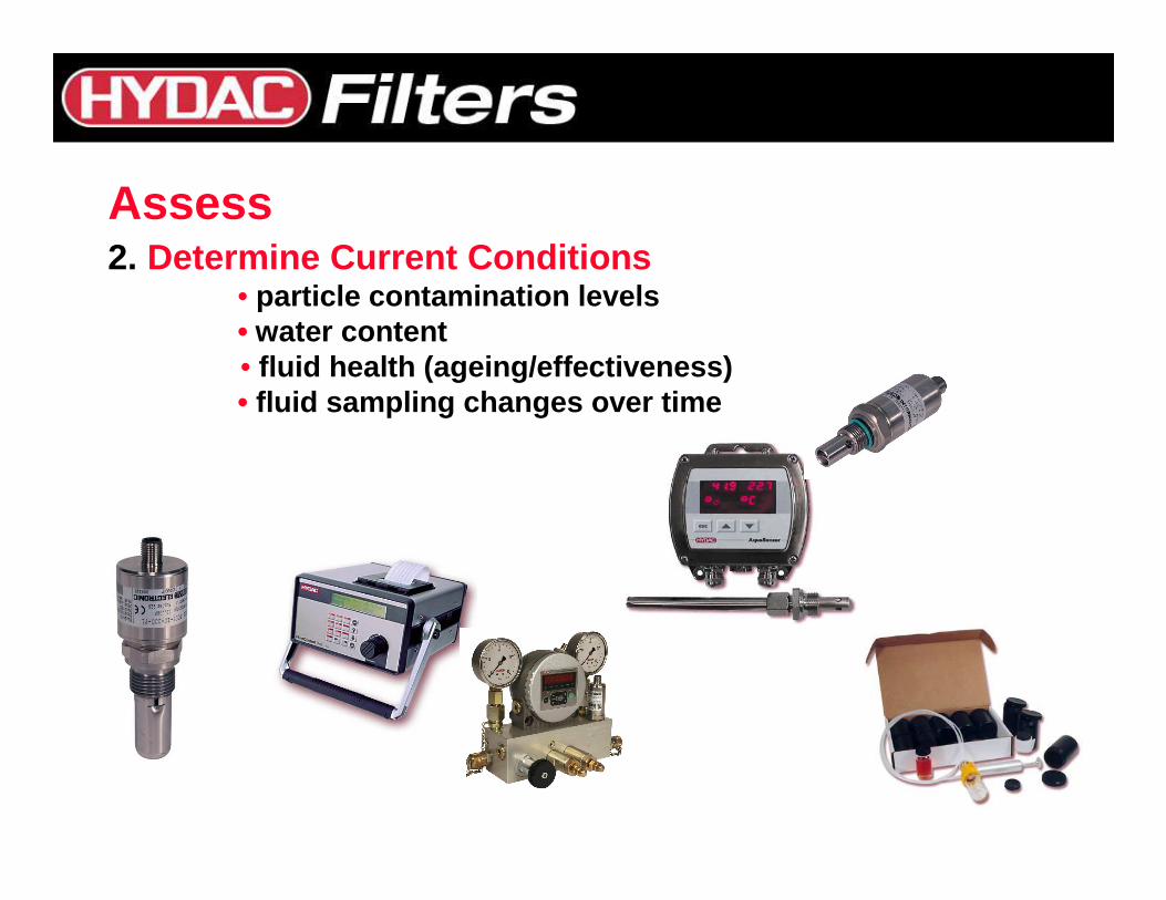
Assess2. Determine Current Conditions
• particle contamination levels• water content • fluid health (ageing/effectiveness)• fluid sampling changes over time
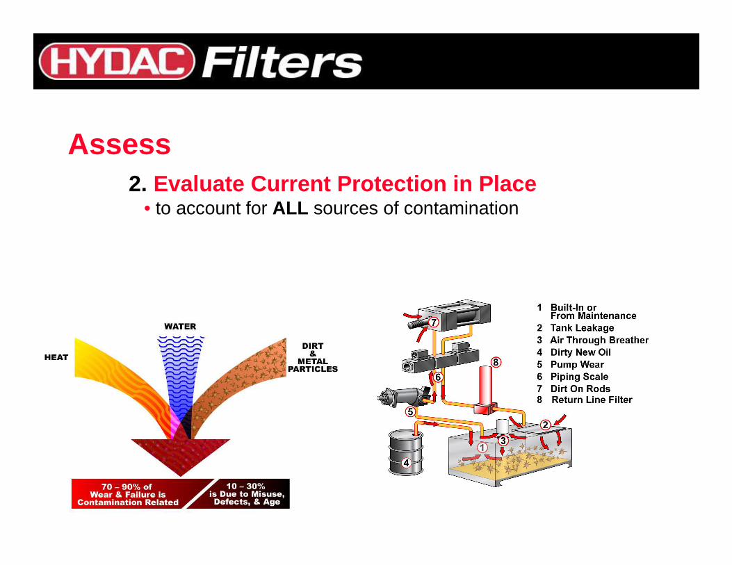
Assess2. Evaluate Current Protection in Place
• to account for ALL sources of contamination
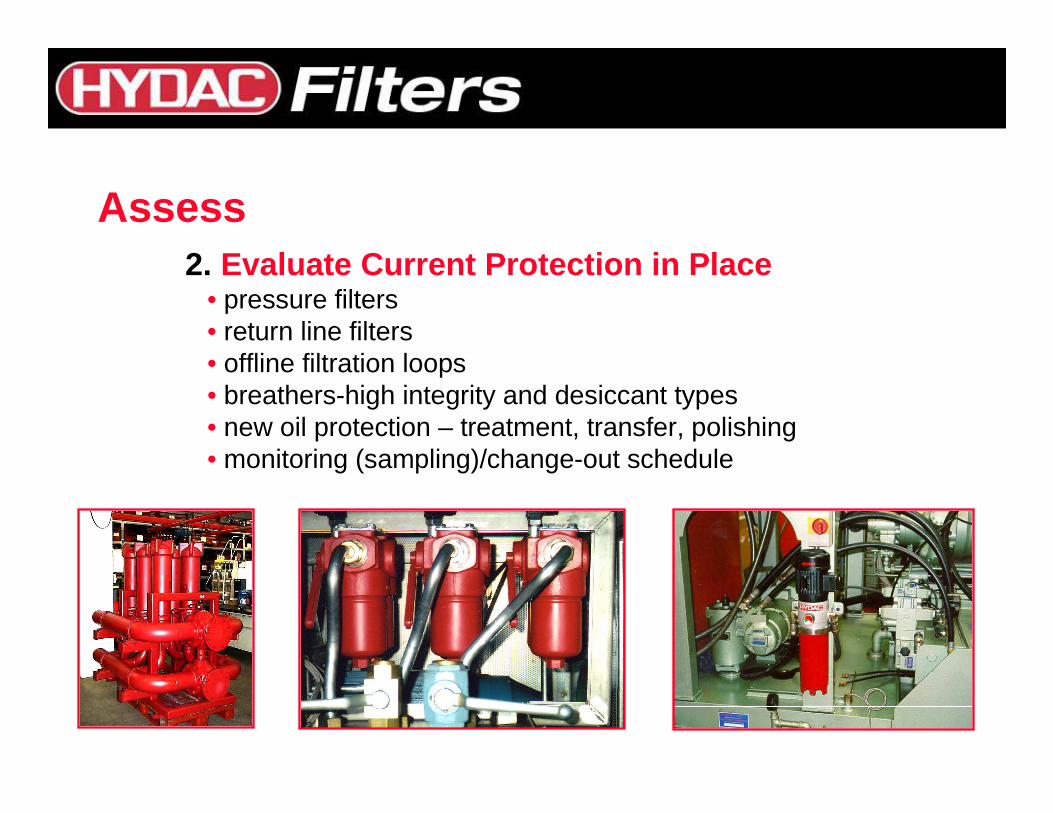
Assess2. Evaluate Current Protection in Place
• pressure filters• return line filters• offline filtration loops• breathers-high integrity and desiccant types• new oil protection – treatment, transfer, polishing• monitoring (sampling)/change-out schedule
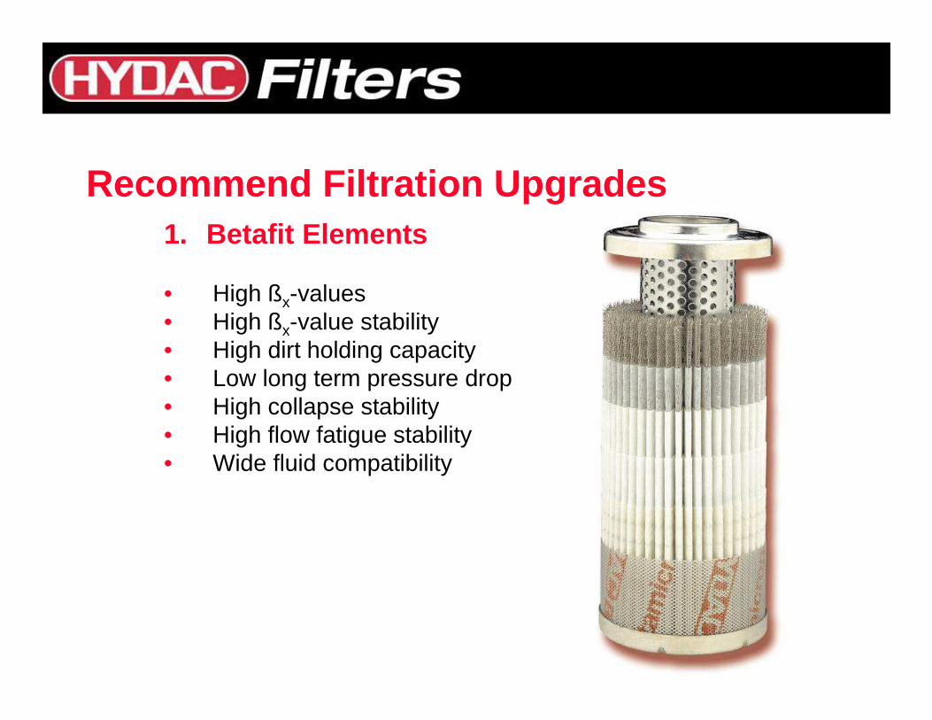
Recommend Filtration Upgrades1. Betafit Elements
• High ßx-values• High ßx-value stability• High dirt holding capacity• Low long term pressure drop• High collapse stability• High flow fatigue stability• Wide fluid compatibility
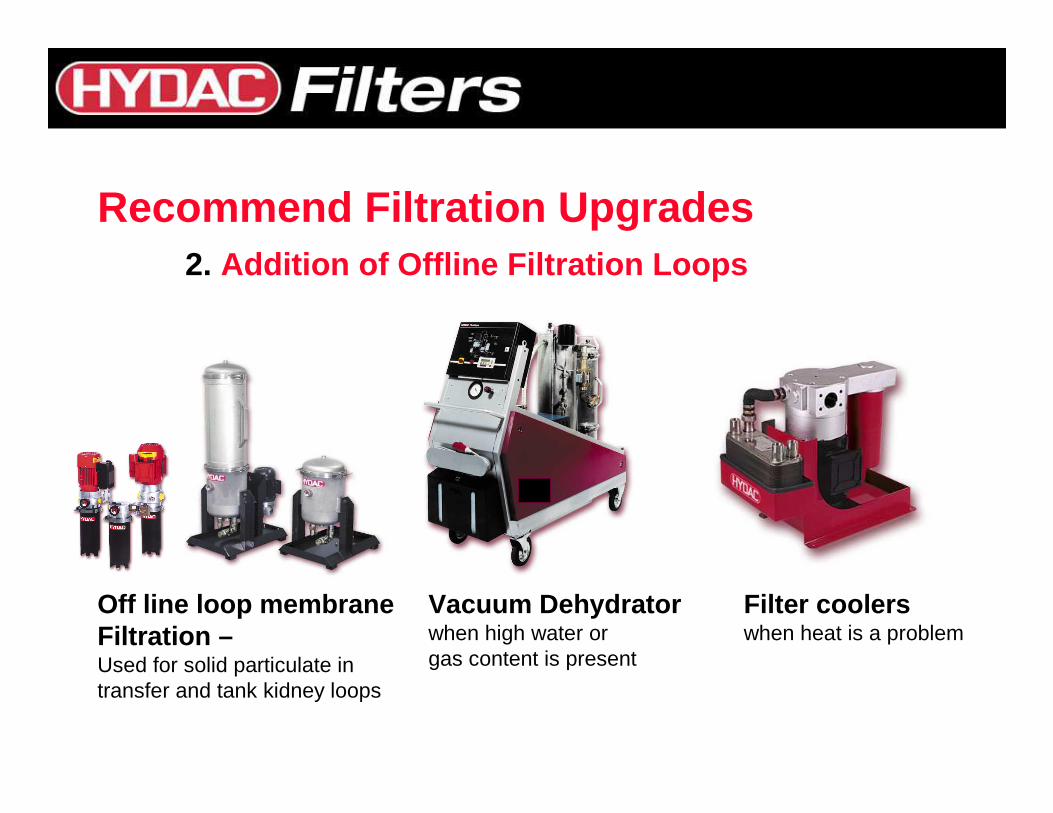
Recommend Filtration Upgrades2. Addition of Offline Filtration Loops
Vacuum Dehydratorwhen high water orgas content is present
Off line loop membraneFiltration –Used for solid particulate in transfer and tank kidney loops
Filter coolerswhen heat is a problem
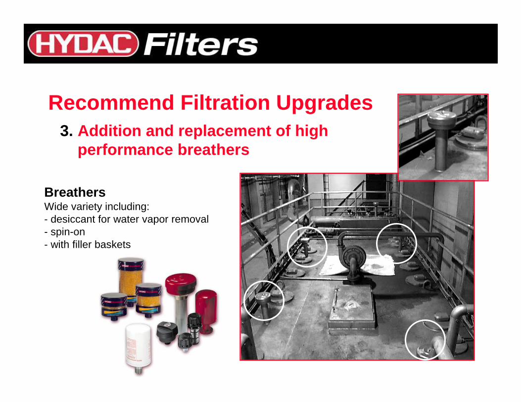
Recommend Filtration Upgrades3. Addition and replacement of high
performance breathers
BreathersWide variety including:- desiccant for water vapor removal- spin-on- with filler baskets
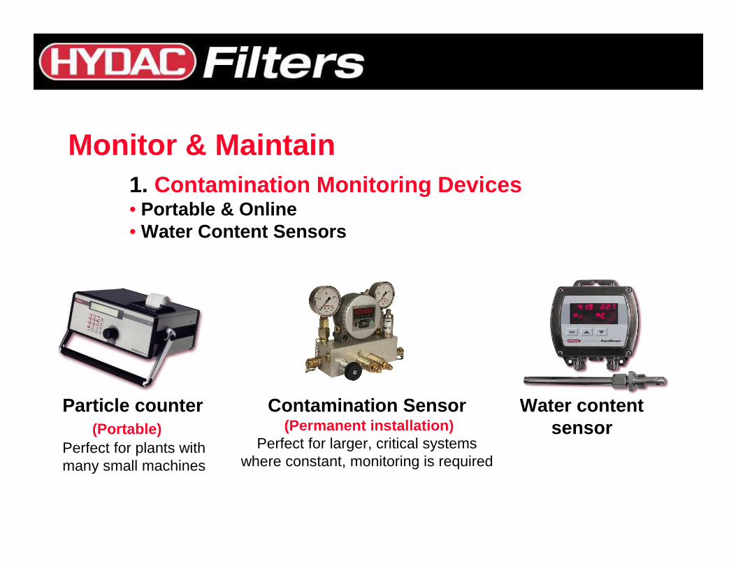
Monitor & Maintain1. Contamination Monitoring Devices • Portable & Online• Water Content Sensors
Particle counter(Portable)
Perfect for plants withmany small machines
Contamination Sensor(Permanent installation)
Perfect for larger, critical systemswhere constant, monitoring is required
Water contentsensor
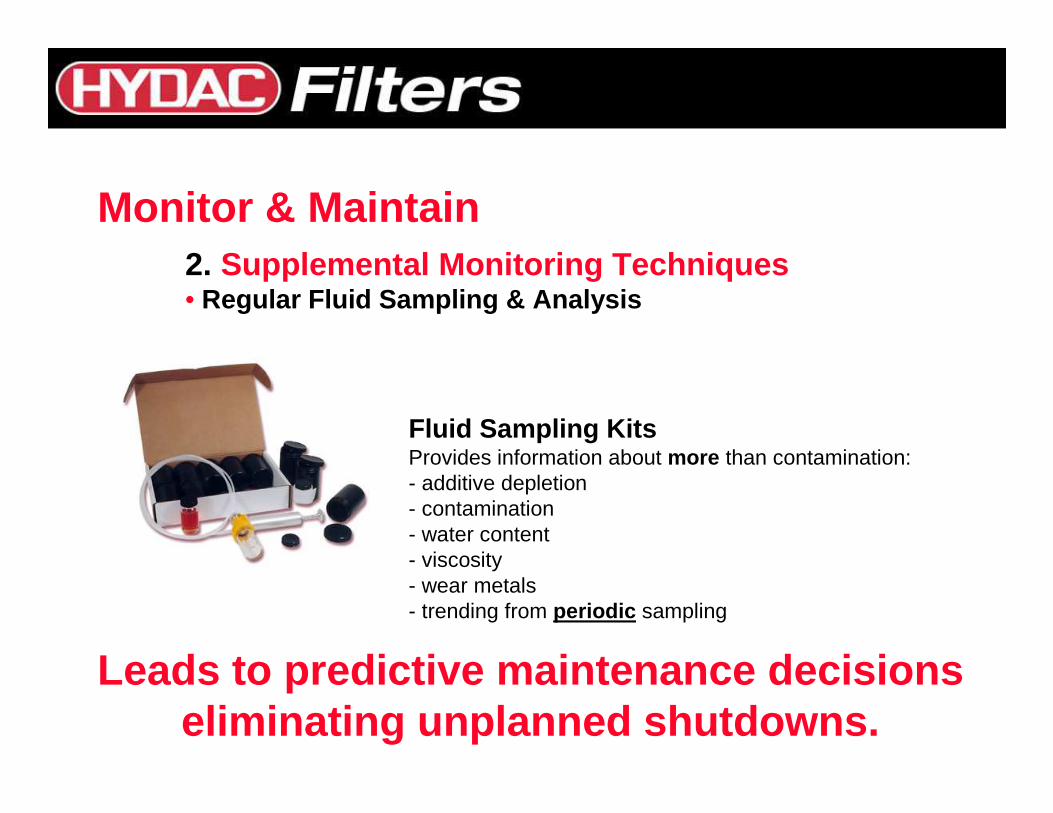
2. Supplemental Monitoring Techniques • Regular Fluid Sampling & Analysis
Fluid Sampling KitsProvides information about more than contamination:- additive depletion- contamination- water content- viscosity- wear metals- trending from periodic sampling
Monitor & Maintain
Leads to predictive maintenance decisionseliminating unplanned shutdowns.
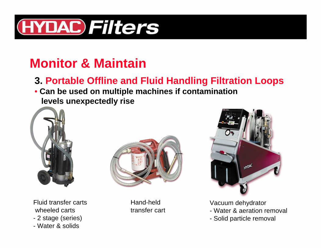
3. Portable Offline and Fluid Handling Filtration Loop s • Can be used on multiple machines if contamination
levels unexpectedly rise
Monitor & Maintain
Fluid transfer cartswheeled carts- 2 stage (series)- Water & solids
Hand-held transfer cart
Vacuum dehydrator- Water & aeration removal- Solid particle removal
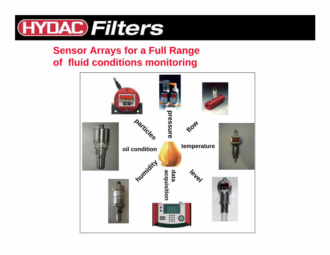
particles
pressure flow
temperaturelevel
dataacquisition
humidi
ty
oil condition
Sensor Arrays for a Full Range of fluid conditions monitoring
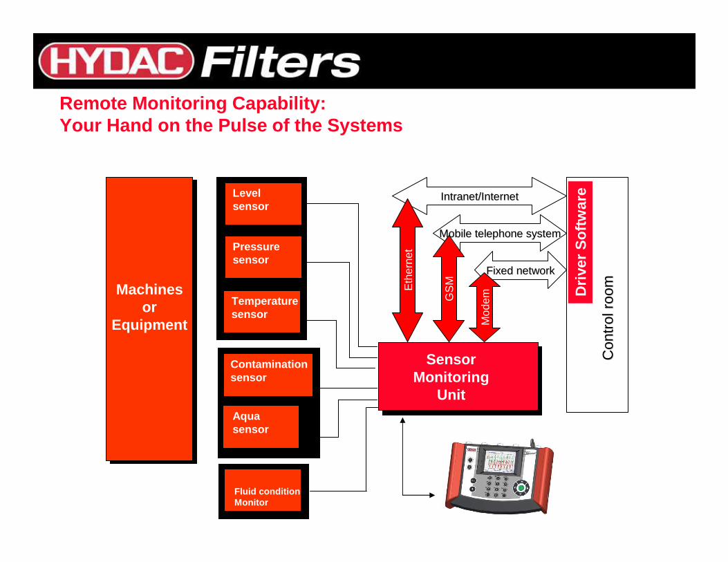
Remote Monitoring Capability:Your Hand on the Pulse of the Systems
Machinesor
Equipment
IntranetIntranet/Internet/Internet
Con
trol
roo
mC
ontr
ol r
oom
Levelsensor
Pressuresensor
Temperaturesensor
Contaminationsensor
Aquasensor
SensorMonitoring
Unit
Mobile Mobile telephone systemtelephone system
Fixed networkFixed network
Eth
erne
t
GS
M
Mod
emFluid conditionMonitor
Driv
er S
oftw
are
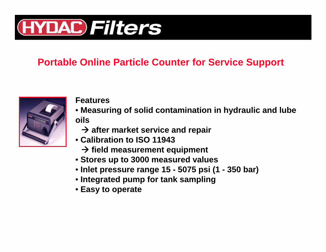
Features• Measuring of solid contamination in hydraulic and l ube oils���� after market service and repair
• Calibration to ISO 11943���� field measurement equipment
• Stores up to 3000 measured values• Inlet pressure range 15 - 5075 psi (1 - 350 bar)• Integrated pump for tank sampling• Easy to operate
Portable Online Particle Counter for Service Support
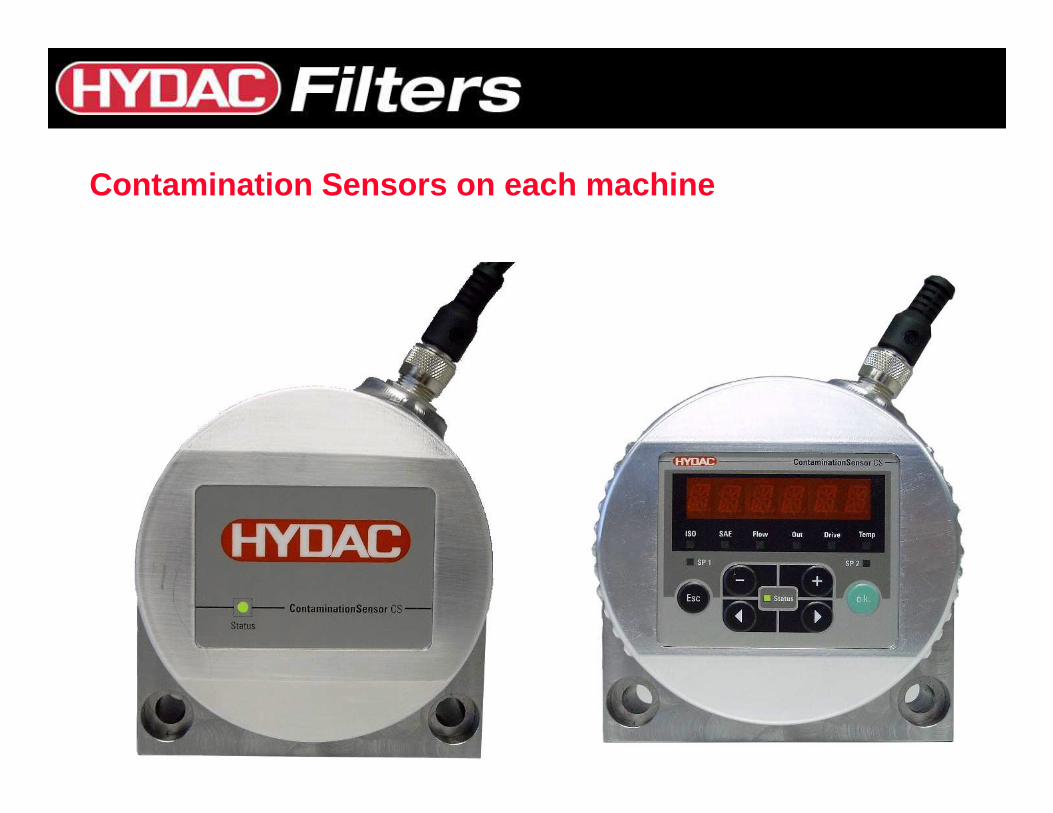
Contamination Sensors on each machine
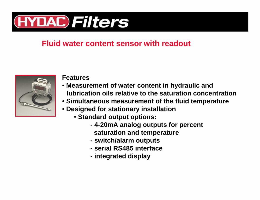
Features• Measurement of water content in hydraulic and
lubrication oils relative to the saturation concent ration • Simultaneous measurement of the fluid temperature• Designed for stationary installation
• Standard output options: - 4-20mA analog outputs for percent saturation and temperature
- switch/alarm outputs- serial RS485 interface- integrated display
Fluid water content sensor with readout
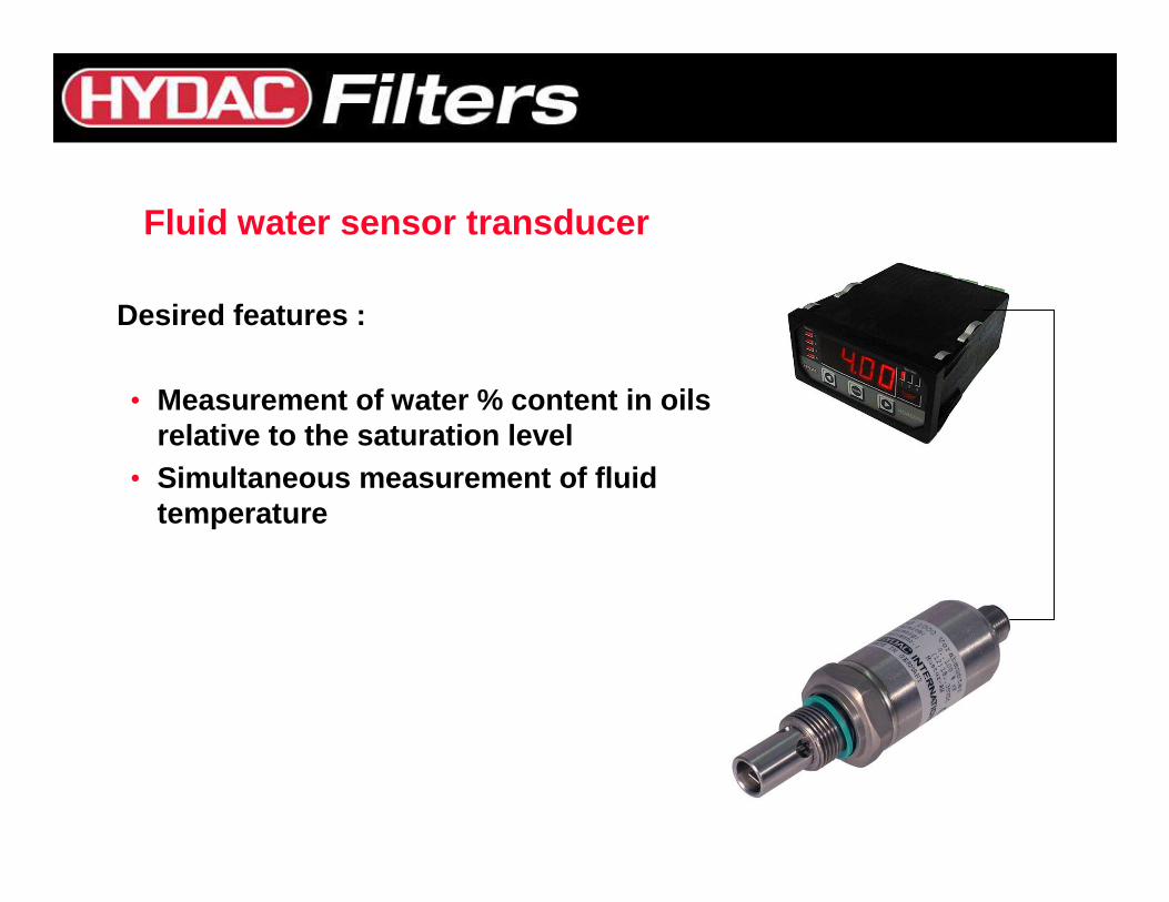
Fluid water sensor transducer
Desired features :
• Measurement of water % content in oilsrelative to the saturation level
• Simultaneous measurement of fluid temperature
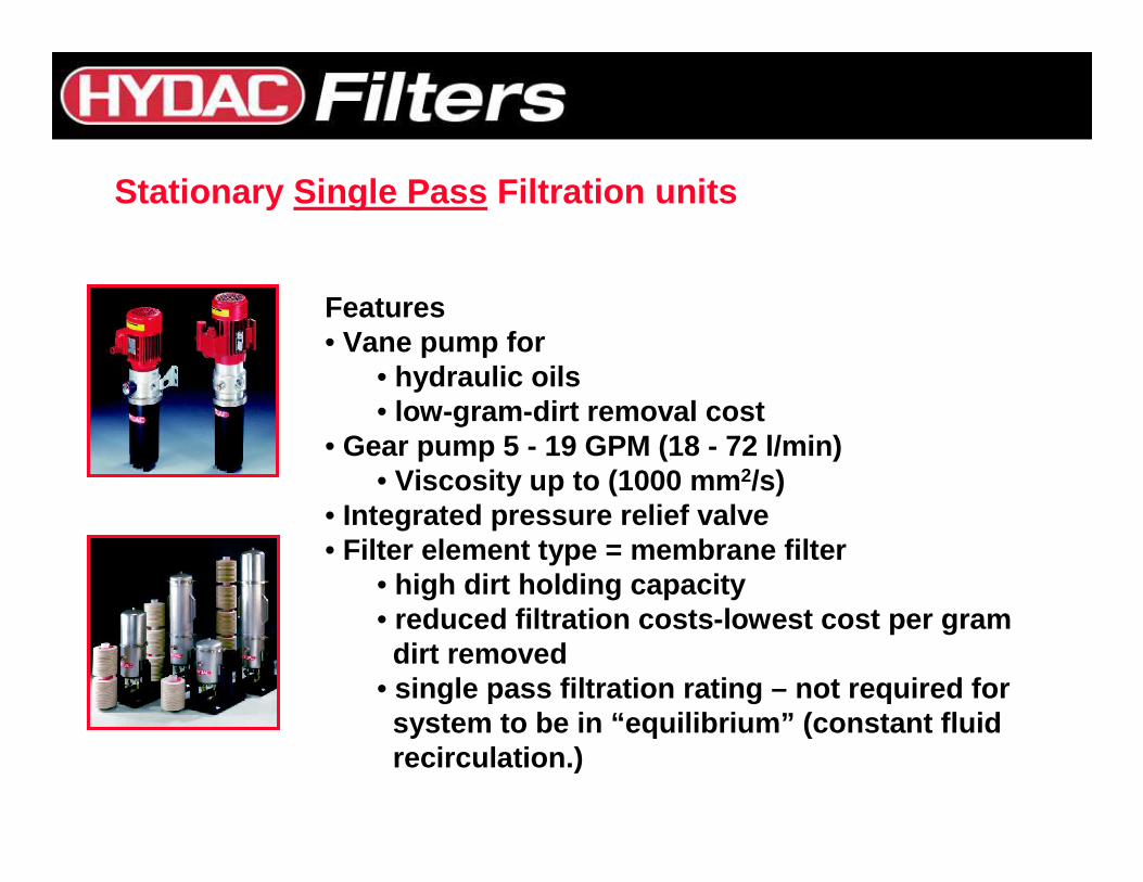
Features• Vane pump for
• hydraulic oils• low-gram-dirt removal cost
• Gear pump 5 - 19 GPM (18 - 72 l/min)• Viscosity up to (1000 mm 2/s)
• Integrated pressure relief valve• Filter element type = membrane filter
• high dirt holding capacity• reduced filtration costs-lowest cost per gramdirt removed
• single pass filtration rating – not required forsystem to be in “equilibrium” (constant fluid recirculation.)
Stationary Single Pass Filtration units
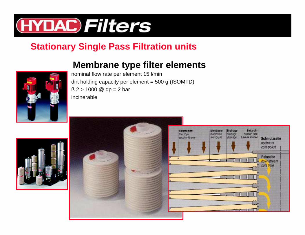
Membrane type filter elementsnominal flow rate per element 15 l/mindirt holding capacity per element = 500 g (ISOMTD)ß 2 > 1000 @ dp = 2 barincinerable
Stationary Single Pass Filtration units