Embed Size (px)
Citation preview

ACE Engineering Academy Hyderabad|Delhi|Bhopal|Pune|Bhubaneswar|Lucknow|Patna|Bengaluru|Chennai|Vijayawada|Vizag|Tirupati|Kukatpally|Kolkata|Ahmedabad
: 2 : ESE - 2019 Main Test Series
ACE Engineering Academy Hyderabad|Delhi|Bhopal|Pune|Bhubaneswar|Lucknow|Patna|Bengaluru|Chennai|Vijayawada|Vizag|Tirupati|Kukatpally|Kolkata|Ahmedabad
01(a).
Sol: The wetted surface of the model is
considered as an equivalent flat plate 3.0 m
long and having a surface area of 3.50 m2.
Reynolds Number,
UL
ReL
6
6109
100.1
0.30.3
The boundary layer is turbulent and the drag
coefficient appropriate to this ReL = 9106 is
L
5/1
L
DfRe
1700
Re
074.0C
65/16 1000.9
1700
1000.9
074.0
= 2.82 10–3
Drag force due to skin friction
2
UareaCF
2
DfDf
2
39985.31082.2
2
3 = 44.3 N
Total measured drag
= skin friction drag + wave drag
70.0 = 44.3 + FDW
Wave drag , FDW = 70.0 – 44.3 = 25.7 N
01(b).
Sol: Comparison of Otto, Diesel and Dual
cycles :
Generally Otto, Diesel and Dual cycles are
compared.
For any comparison ‘dual cycle’ is always in
between Otto and Diesel cycle.
The three cycles can be compared on the
basis of either the same compression ratio or
the same maximum pressure and
temperature.
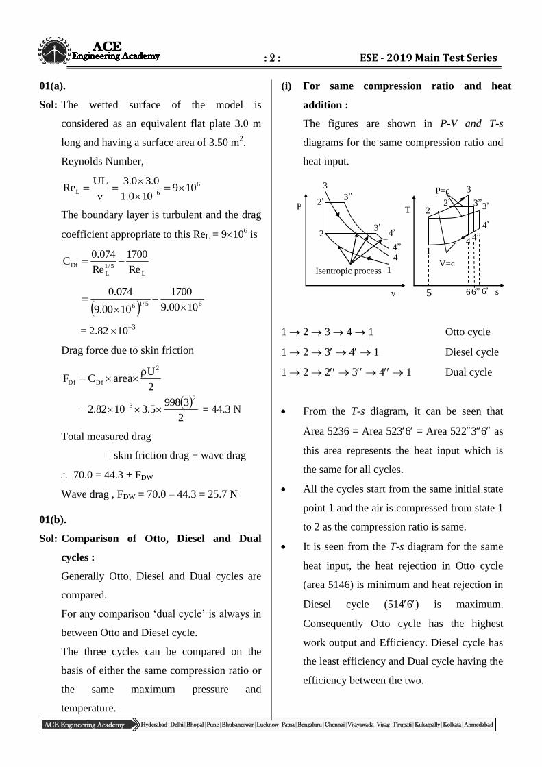
(i) For same compression ratio and heat
addition :
The figures are shown in P-V and T-s
diagrams for the same compression ratio and
heat input.
1 2 3 4 1 Otto cycle
1 2 3 4 1 Diesel cycle
1 2 2 3 4 1 Dual cycle
From the T-s diagram, it can be seen that
Area 5236 = Area 5236 = Area 52236 as
this area represents the heat input which is
the same for all cycles.
All the cycles start from the same initial state
point 1 and the air is compressed from state 1
to 2 as the compression ratio is same.
It is seen from the T-s diagram for the same
heat input, the heat rejection in Otto cycle
(area 5146) is minimum and heat rejection in
Diesel cycle (5146) is maximum.
Consequently Otto cycle has the highest
work output and Efficiency. Diesel cycle has
the least efficiency and Dual cycle having the
efficiency between the two.
3
Isentropic process
P
2
1
3’
3’’
4’
4’’ 4
2’
v
2’ 2
1
4’’ 4
4’
3’’
6’’ 6’ 6
T
s
P=c
V=c
3
5
3’
: 3 : ME_ Mock - 1 (Paper -1)_Solutions
ACE Engineering Academy Hyderabad|Delhi|Bhopal|Pune|Bhubaneswar|Lucknow|Patna|Bengaluru|Chennai|Vijayawada|Vizag|Tirupati|Kukatpally|Kolkata|Ahmedabad
From the above diagrams
(Peak pressure)Otto > (Peak pressure)Diesel
(Peak temp.)Otto > (Peak temp)Diesel
(Expansion ratio)Otto > (Expansion ratio)Diesel
(Temp at beginning of heat rejection)Otto <
(Temp at beginning of heat rejection)Diesel
(Heat rejected)Otto < (Heat rejected)Diesel
(Work)Otto > (Work)Diesel
DieselthOtto )()( th
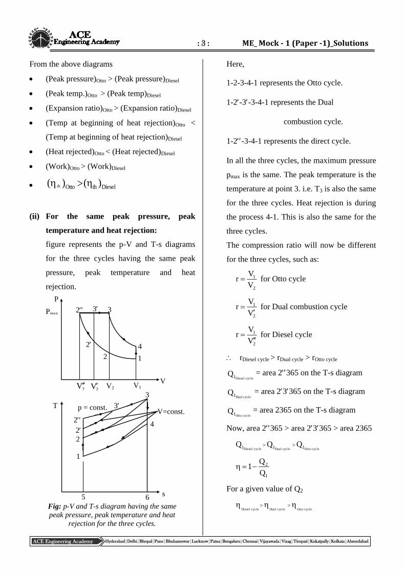
(ii) For the same peak pressure, peak
temperature and heat rejection:
figure represents the p-V and T-s diagrams
for the three cycles having the same peak
pressure, peak temperature and heat
rejection.
Here,
1-2-3-4-1 represents the Otto cycle.
1-2-3-3-4-1 represents the Dual
combustion cycle.
1-2-3-4-1 represents the direct cycle.
In all the three cycles, the maximum pressure
pmax is the same. The peak temperature is the
temperature at point 3. i.e. T3 is also the same
for the three cycles. Heat rejection is during
the process 4-1. This is also the same for the
three cycles.
The compression ratio will now be different
for the three cycles, such as:
2
1
V
Vr for Otto cycle
2
1
V
Vr
for Dual combustion cycle
2
1
V
Vr
for Diesel cycle
rDiesel cycle > rDual cycle > rOtto cycle
cycleDiesel1Q = area 2365 on the T-s diagram
cycleDual1Q = area 23365 on the T-s diagram
cycleOtto1Q = area 2365 on the T-s diagram
Now, area 2365 > area 23365 > area 2365
cycleDiesel1Q >
cycleDual1Q >cycleOtto1Q
1
2
Q
Q1
For a given value of Q2
cycleDiesel
>cycleDual
>cycleOtto
V2 V1 V
4
2
2
3 3 2
2V 2V
Pmax
P
1
Fig: p-V and T-s diagram having the same
peak pressure, peak temperature and heat
rejection for the three cycles.
4
T
1
5
2
2
2
6
3
V=const. p = const. 3
s
: 4 : ESE - 2019 Main Test Series
ACE Engineering Academy Hyderabad|Delhi|Bhopal|Pune|Bhubaneswar|Lucknow|Patna|Bengaluru|Chennai|Vijayawada|Vizag|Tirupati|Kukatpally|Kolkata|Ahmedabad
01(c).
Sol: Given data :
Dp = 20 cm, L = 40 cm,
Ds = 10 cm, N = 90 rpm
When slip is ignored theoretical discharge
and actual discharge is same.
60
NLD
460
NLAQQ 2
p
p
th
60
904.02.0
4
2
= 18.85 lit/s
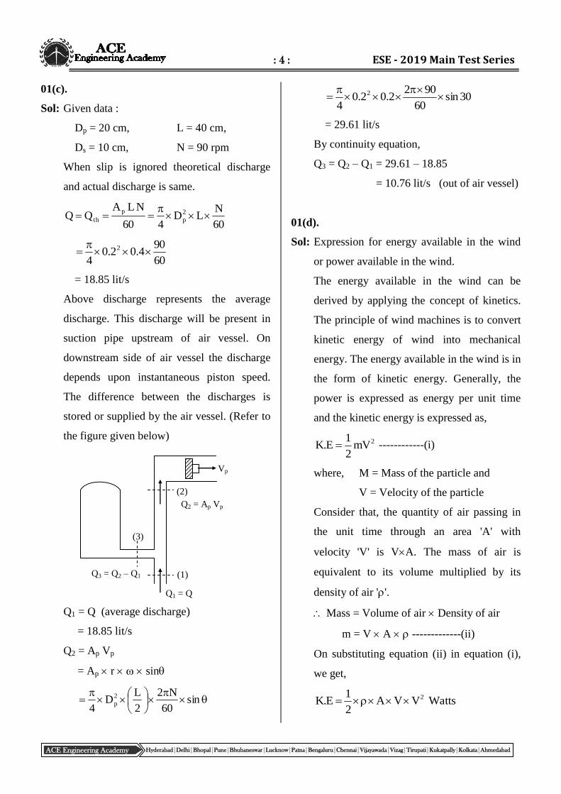
Above discharge represents the average
discharge. This discharge will be present in
suction pipe upstream of air vessel. On
downstream side of air vessel the discharge
depends upon instantaneous piston speed.
The difference between the discharges is
stored or supplied by the air vessel. (Refer to
the figure given below)
Q1 = Q (average discharge)
= 18.85 lit/s
Q2 = Ap Vp
= Ap r sin
sin
60
N2
2
LD
4
2
p
30sin60
9022.02.0
4
2
= 29.61 lit/s
By continuity equation,
Q3 = Q2 – Q1 = 29.61 – 18.85
= 10.76 lit/s (out of air vessel)
01(d).
Sol: Expression for energy available in the wind
or power available in the wind.
The energy available in the wind can be
derived by applying the concept of kinetics.
The principle of wind machines is to convert
kinetic energy of wind into mechanical
energy. The energy available in the wind is in
the form of kinetic energy. Generally, the
power is expressed as energy per unit time
and the kinetic energy is expressed as,
2mV2
1E.K ------------(i)
where, M = Mass of the particle and
V = Velocity of the particle
Consider that, the quantity of air passing in
the unit time through an area 'A' with
velocity 'V' is VA. The mass of air is
equivalent to its volume multiplied by its
density of air ''.
Mass = Volume of air Density of air
m = V A -------------(ii)
On substituting equation (ii) in equation (i),
we get,
WattsVVA2
1E.K 2
(3)
(1)
(2)
Vp
Q3 = Q2 – Q1
Q1 = Q
Q2 = Ap Vp
: 5 : ME_ Mock - 1 (Paper -1)_Solutions
ACE Engineering Academy Hyderabad|Delhi|Bhopal|Pune|Bhubaneswar|Lucknow|Patna|Bengaluru|Chennai|Vijayawada|Vizag|Tirupati|Kukatpally|Kolkata|Ahmedabad
WattsVA2
1E.K 3 ---------(iii)
But, in case of horizontal axis wind turbine,
area is considered as a circular section.
Area of section, 2D4
A
------------(iv)
where, D = Diameter
Now, substituting equation (iv) in equation
(iii), we get,
32 VD42
1PorE.K
WattsVD8
PorE.K 32
The above equation represents the energy
available in the wind or power available in
the wind.
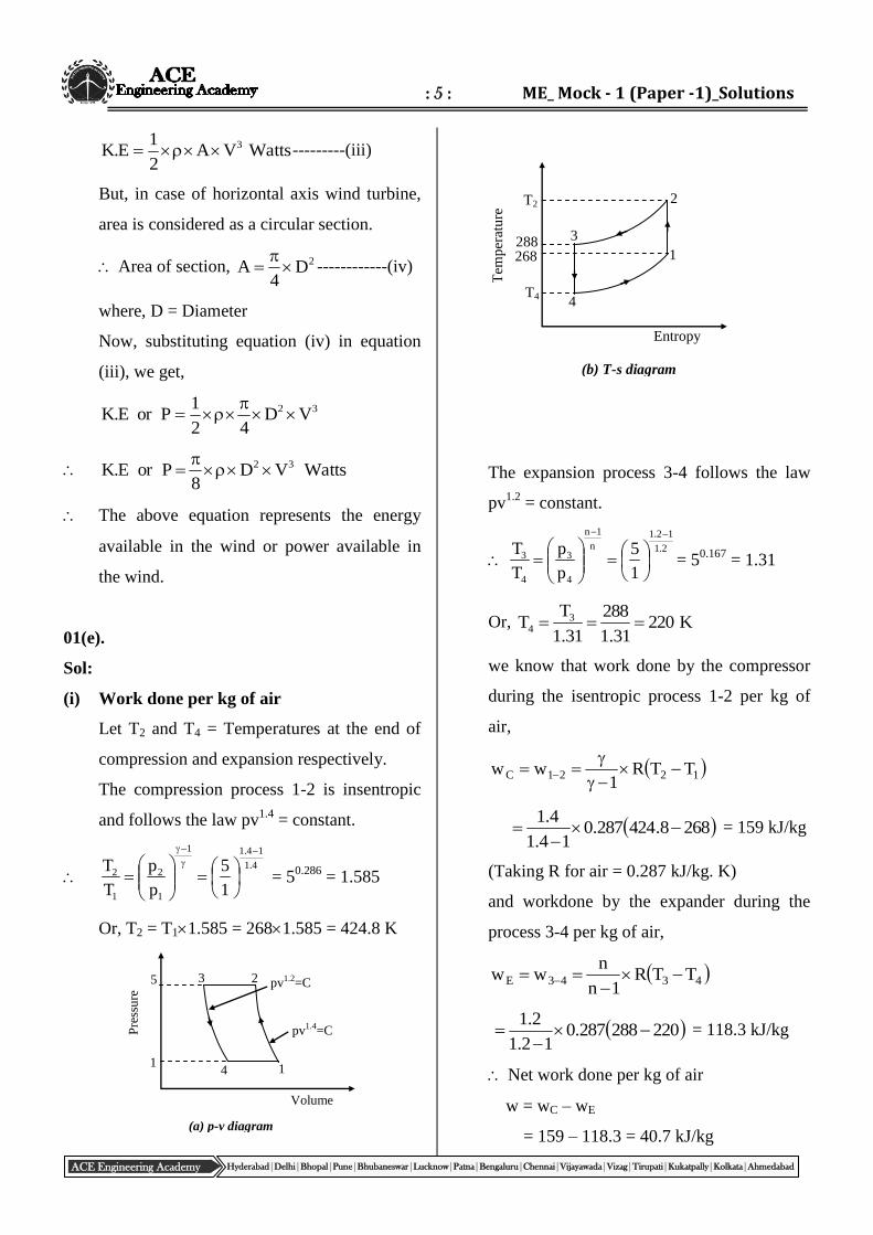
01(e).
Sol:
(i) Work done per kg of air
Let T2 and T4 = Temperatures at the end of
compression and expansion respectively.
The compression process 1-2 is insentropic
and follows the law pv1.4
= constant.
4.1
14.11
1
2
1
2
1
5
p
p
T
T
= 5
0.286 = 1.585
Or, T2 = T11.585 = 2681.585 = 424.8 K
The expansion process 3-4 follows the law
pv1.2
= constant.
2.1
12.1
n
1n
4
3
4
3
1
5
p
p
T
T
= 5
0.167 = 1.31
Or, K22031.1
288
31.1
TT 3
4
we know that work done by the compressor
during the isentropic process 1-2 per kg of
air,
1221C TTR1
ww
2688.424287.014.1
4.1
= 159 kJ/kg
(Taking R for air = 0.287 kJ/kg. K)
and workdone by the expander during the
process 3-4 per kg of air,
4343E TTR1n
nww
220288287.012.1
2.1
= 118.3 kJ/kg
Net work done per kg of air
w = wC – wE
= 159 – 118.3 = 40.7 kJ/kg
(b) T-s diagram
268 288
Tem
per
atu
re T2
T4 4
3
1
2
Entropy
Volume
Pre
ssu
re
1 4 1
pv1.4=C
pv1.2=C 3 5
(a) p-v diagram
2
: 6 : ESE - 2019 Main Test Series
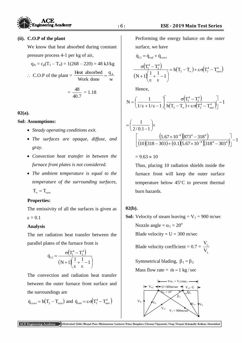
ACE Engineering Academy Hyderabad|Delhi|Bhopal|Pune|Bhubaneswar|Lucknow|Patna|Bengaluru|Chennai|Vijayawada|Vizag|Tirupati|Kukatpally|Kolkata|Ahmedabad
Vw1 = V1cos1
Vw2 U=300m/sec Vw1–U
Vr1 Vf2
Vr2 Vf1
2 1 1 = 20o
V2
V1 = 900m/sec
(ii). C.O.P of the plant
We know that heat absorbed during constant
pressure process 4-1 per kg of air,
qA = cp(T1 – T4) = 1(268 – 220) = 48 kJ/kg
C.O.P of the plant = w
q
doneWork
absorbedHeat A
= 7.40
48 = 1.18
02(a).
Sol: Assumptions:
Steady operating conditions exit.
The surfaces are opaque, diffuse, and
gray.
Convection heat transfer in between the
furnace front plates is not considered.
The ambient temperature is equal to the
temperature of the surrounding surfaces,
surrTT
Properties:
The emissivity of all the surfaces is given as
= 0.1
Analysis
The net radiation heat transfer between the
parallel plates of the furnace front is
111
1N
TTq
4
2
4
112
The convection and radiation heat transfer
between the outer furnace front surface and
the surroundings are
surr2conv TThq and 4
surr
4
2rad TTq
Performing the energy balance on the outer
surface, we have
convrad12 qqq
4
surr
4
22
4
2
4
1 TTTTh
111
1N
TT
Hence,
1TTTTh
TT
1/1/1
1N
4
surr
4
22
4
2
4
1
11.0/2
1
13033181067.51.030331810
3188731067.5448
448
= 9.63 10
Thus, placing 10 radiation shields inside the
furnace front will keep the outer surface
temperature below 45C to prevent thermal
burn hazards.
02(b).
Sol: Velocity of steam leaving = V1 = 900 m/sec
Nozzle angle = 1 = 20o
Blade velocity = U = 300 m/sec
Blade velocity coefficient = 0.7 =
1
2
r
r
V
V
Symmetrical blading, 1 = 2
Mass flow rate = sec/kg1m
: 7 : ME_ Mock - 1 (Paper -1)_Solutions
ACE Engineering Academy Hyderabad|Delhi|Bhopal|Pune|Bhubaneswar|Lucknow|Patna|Bengaluru|Chennai|Vijayawada|Vizag|Tirupati|Kukatpally|Kolkata|Ahmedabad
Velocity of whirl at inlet = Vw1 = V1 cos1
= 900 cos20
= 845.73 m/sec
Vw1 – U = 845.73 – 300 = 545.73 m/sec
Velocity of flow at inlet = Vf1 = V1 sin1
= 900 sin20
= 307.83 m/sec
73.545
82.307
UV
Vtan
1w
1f1
1 = 29.43o = 2
1r
1f1
V
Vsin
sec/m47.62643.29sin
82.307
sin
VV
o
1
f
r1
1
7.0V
V
1
2
r
r (given)
Vr2 = 0.7 Vr1 = 0.7626.47=438.53 m/sec
Velocity of whirl at exit
Vw2 = Vr2 cos2 – U
Vw2 = 438.53 cos29.43 – 300 = 81.56 m/sec
Velocity of flow at exit = Vf2 = Vr2 sin2
= 438.53 sin29.43
= 215.47 m/sec
Power on wheel =
1000
WVU.m21 ww
1000
56.8173.8453001
= 278.19 kW
Force on wheel =
1000
VVm21 ww
kN9273.01000
56.8173.8451
Axial thrust = 21 ff VVm
47.21582.3071
= 92.35 N
)kW(inputEnergy
)kW(PowerefficiencyDiagram
kW1000
Vm
2
1
)kW(Power2
1
kW1000
9001
2
1
kW19.2782
= 0.6868
02(c).
Sol: Gas required for lighting
= 10 0.227 4 = 9.08 m3/day
Electrical energy required by ten computers
= 10 250 6 60 60 = 54 MJ
Assuming the conversion efficiency of
generator to be 80% and the thermal
efficiency of the engine to be 25%, the
thermal input to the engine to generate 54 MJ
electrical energy = 54(0.250.80) = 270 MJ
Mechanical energy required for water
pumping = 274626060 = 10.74 MJ
Assuming the thermal efficiency of engine to
be 25%, the required thermal input
= 42.96 MJ
Total thermal input required by the engine
= 312.96 MJ
Assuming the heating value of biogas to be
23 MJ/m3, the required volume of biogas for
the engine = 23
96.312 = 13.61 m
3/day
Therefore, total daily requirement of biogas
= 9.08 + 13.61 = 22.69 m3
: 8 : ESE - 2019 Main Test Series
ACE Engineering Academy Hyderabad|Delhi|Bhopal|Pune|Bhubaneswar|Lucknow|Patna|Bengaluru|Chennai|Vijayawada|Vizag|Tirupati|Kukatpally|Kolkata|Ahmedabad
Let the cows required to feed the plant = n
Collectable cow dung per day = 7n kg/day
Weight of solid mass (18%) in the cow dung
= 7n 0.18 = 1.26 n kg/day
Assuming gas yield of 0.34 m3/kg of dry
mass, the gas produced per day
= 1.26n 0.34 = 0.4284n m3/day
Therefore, 0.4284 n = 22.69
n = 52.96
n = 53
Thus, 53 cows are required to feed the plant.
Daily feeding of cow dung into the plant
= 7 53 = 371 kg
This will be mixed with equal quantity of
water to make the slurry. Thus the daily
slurry produced = 371 + 371 = 742 kg
Assuming slurry density to be 1090 kg/m3,
the volume of slurry added per day
= 1090
742 = 0.6807 m
3
For a 50 day retention time, the total volume
of the slurry in the digester
= 500.6807 = 34.035 m3
As only 90% of the digester volume is
occupied by the slurry, the net volume of the
digester = 9.0
035.34 = 37.82 m
3
03(a),
Sol: Given data,
H = 400 m, D = 20 m,
Tf = 8 kN.m, N = 350 rpm,
Q = 0.75 m3/s , cv = 0.98
180 - 2 = 170
m = 0.9 , k = 0.9
The overall efficiency is the product of all
efficiencies
o = n w m v
Assuming volumetric efficiency (v) as 1
we get , o = n w m
The nozzle efficiency is given by
n = cv2 = (0.98)
2 = 0.9604
The wheel efficiency (w) is given by
2
2w
V
cosk1uvu2 --------(i)
The jet velocity (V) is given by
gH2CV v
40081.929.0 = 86.82 m/s
The bucket velocity (u) is given by
60
DNu
s/m32.40
60
3502.2
Substituting in eq. (1) we get
2w82.86
10cos9.0132.4082.8632.402
= 0.938
o = 0.9604 0.938 0.93 = 0.838
At normal running speed of 350 rpm the
bucket speed is 40.32 m/s. Hence, the torque
at normal speed is
T = aV (V – u) (1 + k cos2) R
= Q (V – u) (1 + k cos2) R [∵ Q = aV]
= 1000 0.75 (86.82 – 40.32) ( 1 +0.9
cos10) 1.1
= 72.36 kN.m
: 9 : ME_ Mock - 1 (Paper -1)_Solutions
ACE Engineering Academy Hyderabad|Delhi|Bhopal|Pune|Bhubaneswar|Lucknow|Patna|Bengaluru|Chennai|Vijayawada|Vizag|Tirupati|Kukatpally|Kolkata|Ahmedabad
At start, the bucket speed is zero
Tstart = Q (V – 0) (1 + k cos2) R
= 10000.75 (86.82 – 0) (1 +0.9 cos10) 1.1
= 135.11 kN.m
The runaway speed is the speed of runner
corresponding to maximum possible bucket
speed. Under no load condition, bucket can
reach theoretical maximum speed equal to jet
speed. This happens when frictional torque
acting on the wheel is zero. At theoretical
runaway speed (NR,th) the bucket speed (uR,th)
is equal to jet velocity.
Vu th,R
V60
DN th,R
82.8660
N2.2 th,R
NR,th = 753.7 rpm
In reality actual runaway speed (NR) will be
slightly less than the theoretical runaway
speed due to frictional loss. At actual
runaway speed, torque developed by the
runner is exactly equal to torque required to
overcome frictional resistance.
Tf = Q (V – uR) (1 + k cos2) R
8 103 = 1000 0.75 (86.82 – uR) (1 +0.9
cos10) 1.1
uR = 81.68 m/s
68.8160
DBNR
2.2
6068.81NR
= 709 rpm
03(b).
Sol: Final temperature of the body will be T2
1
2v
T
T
v12T
Tncm
T
dTcmSS
2
1
[cv = heat energy Cv]
2
reservoirT
WQS
(S)H.E = 0
0T
WQSSS
2
12univ
T2 (S2 – S1) + Q – W 0
W Q + T2 (S2 – S1)
W [Q – T2 (S1 – S2)]
Wmax = [Q – T2(S1 – S2)]
1
2v2
T
TnCTQ
1
2v221v
T
TnCTTTC
373
303n3033033734.8
= 58.99 kJ
03(c).
Sol:
(i) Theoretical power required:
First of all, let us find the temperature of
superheated vapour at point 2(T2).
We know that entropy at point 1,
1
1pv11
T
Tlogc3.2ss
245
250log615.03.27153.0 = 0.7277
-------- (1)
: 10 : ESE - 2019 Main Test Series
ACE Engineering Academy Hyderabad|Delhi|Bhopal|Pune|Bhubaneswar|Lucknow|Patna|Bengaluru|Chennai|Vijayawada|Vizag|Tirupati|Kukatpally|Kolkata|Ahmedabad
and entropy at point 2,
2
2pv22
T
Tlogc3.2ss
299
Tlog615.03.26865.0 2
299
Tlog4145.16865.0 2 --------(2)
Since the entropy at point 1 is equal to
entropy at point 2, therefore equating
equations (1) and (2)
299
Tlog4145.16865.07277.0 2
0291.04145.1
6865.07277.0
299
Tlog 2
0693.1299
T2 (Taking antilog of 0.0291)
T2 = 2991.0693 = 319.7 K
We know that enthalpy at point 1,
11pv11 TTchh
245250615.011.175 = 178.18 kJ/kg
Enthalpy at point 2,
22pv22 TTchh
= 198.11+0.615(319.7 – 299)
= 210.84 kJ/kg
Enthalpy of liquid refrigerant at point 3,
33p3f3f TTchh
= 60.67 – 0.963(299–295) = 64.52 kJ/kg
We know that heat extracted or refrigerating
effect per kg of the refrigerant,
RE = h1 – hf3 = 178.18 – 64.52
= 113.66 kJ/kg
Refrigerating capacity of the system,
Q = 12 TR = 12210 = 2520 kJ/min
Mass flow of the refrigerant,
E
RR
Qm
66.113
2520 = 22.17 kg/min
Work done during compression of the
refrigerant= mR(h2 –h1)
= 22.17(210.84 – 178.18)
= 724 kJ/min
Theoretical power required = 60
724= 12.07 kW
(ii). C.O.P
we know that C.O.P12
3f1
hh
hh
18.17884.210
52.6418.178
= 3.48
(iii). Volumetric efficiency
Let 2 = specific volume at point 2, and
C = Clearance = 3% = 0.03 (Given)
First of all, let us find the specific volume at
suction to the compressor, i.e. at point 1.
Applying Charles law to points 1 and 1,
1
1
1
1
TT
Or, 1
111
T
T
245
2501475.0 = 0.1505 m
3/kg
Again applying Charles' law to points 2 & 2,
2
2
2
2
TT
: 11 : ME_ Mock - 1 (Paper -1)_Solutions
ACE Engineering Academy Hyderabad|Delhi|Bhopal|Pune|Bhubaneswar|Lucknow|Patna|Bengaluru|Chennai|Vijayawada|Vizag|Tirupati|Kukatpally|Kolkata|Ahmedabad
Or, 2
222
T
T
299
7.3190262.0 = 0.028 m
3/kg
We know that volumetric efficiency,
028.0
1505.003.003.01CC1
2
1
= 0.87 or 87%
(iv). Bore and stroke of cylinder:
Let D = Bore cylinder,
L = Length of cylinder = 1.25 D and
N = Speed of compressor = 1000 r.p.m
We know that theoretical suction volume or
piston displacement per minute.
1
m 1R
87.0
11505.017.22 = 3.84 m
3/min
Since the machine has six cylinders, single
acting compressor, therefore, theoretical
suction volume or piston displacement per
cylinder per minute.
6
84.3 = 0.64 m
3/min
We also know that suction volume or piston
displacement per minute
= Piston area Stroke R.P.M.
1000D25.1D4
NLD4
22
= 982 D3 m
3/min
Equating equations (3) and (4)
D3 = 0.64/982 = 0.000652
D = 0.0867 m = 86.7 mm
L = 1.2586.7 = 108.4 mm
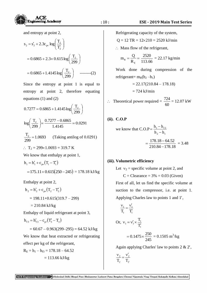
(v) T-s and P-h diagram
04(a).
Sol: Swept volume Vs = 2 litre = 0.002 m3.
Volume of air induced for four-stroke engine
per second 602
N.V. sv
where v is the volumetric efficiency and N
is the engine rpm.
Volume of air induced = 602
4500002.075.0
= 0.05625 m3/s
(a) T-s diagram
1
2
4
3
3 T2
245
250
295
299 2
1
s1 = s2
1s
2s
Entropy
Tem
per
atu
re
Enthalpy
Pre
ssu
re
1
2 2 3
3
4
h2
h1 2h
1h 3h
hf3
(b) p-h diagram
: 12 : ESE - 2019 Main Test Series
ACE Engineering Academy Hyderabad|Delhi|Bhopal|Pune|Bhubaneswar|Lucknow|Patna|Bengaluru|Chennai|Vijayawada|Vizag|Tirupati|Kukatpally|Kolkata|Ahmedabad
Each carburettor delivers an air flow of
2
05625.0 = 0.028125 m
3/s
s/m028125.0V 3
1
288287
028125.010013.1
RT
Vpm
5
1
11a
= 0.03447 kg/s
Velocity at throat,
1
1
21p2
p
p1Tc2C
1
1p
2
2
1
2
Tc2
C1
p
p
5.1
28810052
1001001
= 0.9408
p2 = 1.0130.9408 = 0.953 bar
Density of air,
288287
10013.1
RT
p 5
1
11
= 1.2256 kg/m
3
1
1
212
p
p = 1.2256(0.9408)
1/1.4
= 1.1733 kg/m3
Throat area,
a22
a2
CdC
mA
=
85.01001733.1
03447.0
= (3.45610-4
) m2
= 345.6 mm2
6.345dD4
22
d = 0.4D
Now,
6.345D16.0D4
22
Or, 6.345D4
84.0 2
Or, 84.0
46.345D
= 22.89 mm
f21fjff gZpp2ACdm
14
03447.0
14
mm a
f
= 0.002462 kg/s
For the petrol, the pressure difference across
the main jet is given by
5f2110
750006.081.9953.0013.1gZpp
= 1.013 – 0.953 – 0.00044
= 0.05956 bar = (0.05956105) N/m
2
Area of the jet,
f21ff
ff
gZpp2Cd
mA
51005956.0750266.0
002462.0
= 1.248 10–4
m2 = 1.248 mm
2
248.14df = 1.26 mm
04(b).
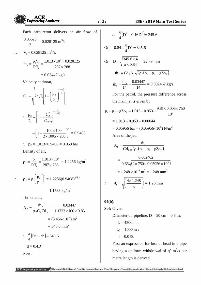
Sol: Given:
Diameter of pipeline, D = 50 cm = 0.5 m;
L = 4500 m ;
L0 = 1000 m ;
f = 0.018.
First an expression for loss of head in a pipe
having a uniform withdrawal of q m
3/s per
metre length is derived.
: 13 : ME_ Mock - 1 (Paper -1)_Solutions
ACE Engineering Academy Hyderabad|Delhi|Bhopal|Pune|Bhubaneswar|Lucknow|Patna|Bengaluru|Chennai|Vijayawada|Vizag|Tirupati|Kukatpally|Kolkata|Ahmedabad
Consider a section at a distance x form the
start of the uniform withdrawal at q per
metre length.
Discharge, Qx = Q0 qx
In a small distance dx,
gD2
fLVh
2
f
dxgD2
fVdh
2
f
Qx = Q0 – q* x
A
x*qQV 0
dxD
1
D4
xqQ
g2
fdh
2
2
0
f
dxxqQgD
f8 2
052
0
0 L
0
3
052
L
0
ff xqQq
1
gD3
f8dhh
3
00
3
052f L*qQQ*q
1
gD3
f8h
here, s/m3.0075.0250
1000Q 3
0
s/m0003.0250
075.0*q 3
L0 = 1000 m
HL = Total head lost = [head lost in first
(4500 – 1000) m with a discharge Qd = 0.3
m3/s] + [Head lost in 1000 m with a uniform
withdrawal of q*] = hf1 + hf2
m3.2481.925.0
5.04
3.03500018.0
h
22
1f
3
00
3
0522f L*qQQ*q
1
gD3
f8h
33
221000003.03.03.0
0003.0
1
5.081.93
018.08
= 1.43 m
Total head loss = 24.3 + 1.43 = 25.73 m
Residual head at the dead end
= 145 – 25.73 = 119.27 m
04(c).
Sol: At 4000 kPa,
Saturation temperature, Ts,b = 250.35oC
At 2.5 kPa,
Saturation temperature, Ts,c = 21.08oC
For maximum increase in efficiency, feed
water heater should be arranged in such a
way that the difference in saturation
temperature at each stage is constant.
Tsat of FWH = 2
TT condener.satboiler.sat
2
08.2135.250
Tsat of FWH = 135.715C
By interpolation :
52.133712.135
300P
52.13327.136
300325 FWH
PFWH = 319.95 kPa
PFWH = 3.19 bar
Q0
50 cm
dia x
dx
Pipeline
L0 = 1000 m
q*
: 14 : ESE - 2019 Main Test Series
ACE Engineering Academy Hyderabad|Delhi|Bhopal|Pune|Bhubaneswar|Lucknow|Patna|Bengaluru|Chennai|Vijayawada|Vizag|Tirupati|Kukatpally|Kolkata|Ahmedabad
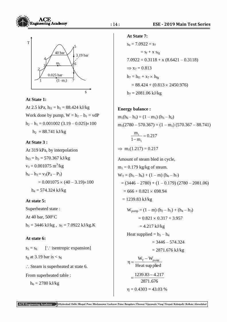
At State 1:
At 2.5 kPa, hf1 = h1 = 88.424 kJ/kg
Work done by pump, W = h2 – h1 = vdP
h2 – h1 = 0.001002 (3.19 – 0.025)100
h2 = 88.741 kJ/kg
At State 3 :
At 319 kPa, by interpolation
hf3 = h3 = 570.367 kJ/kg
v3 = 0.001075 m3/kg
h4 – h3 = v3(P4 – P3)
= 0.001075 (40 – 3.19)100
h4 = 574.324 kJ/kg
At state 5:
Superheated state :
At 40 bar, 500C
h5 = 3446 kJ/kg , s5 = 7.0922 kJ/kg.K
At state 6:
s5 = s6 [∵ isentropic expansion]
sg at 3.19 bar is < s6
∴ Steam is superheated at state 6.
From superheated table :
h6 = 2780 kJ/kg
At State 7:
s6 = 7.0922 = s7
= sf + x sfg
7.0922 = 0.3118 + x (8.6421 – 0.3118)
x7 = 0.813
h7 = hf1 + x7 hfg
= 88.424 + (0.813 2450.976)
h7 = 2081.06 kJ/kg
Energy balance :
m1(h6 – h3) = (1 – m1) (h3 – h2)
m1(2780 – 570.367) = (1 – m1) (570.367 – 88.741)
217.0m1
m
1
1
m1(1.217) = 0.217
Amount of steam bled in cycle,
m1 = 0.179 kg/kg of steam.
WT = (h5 – h6) + (1 – m) (h6 – h7)
= (3446 – 2780) + (1 – 0.179) (2780 – 2081.06)
= 666 + 0.821 698.94
= 1239.83 kJ/kg
Wpump = (1 – m) (h2 – h1) + (h4 – h3)
= 0.821 0.317 + 3.957
= 4.217 kJ/kg
Heat supplied = h5 – h4
= 3446 – 574.324
= 2871.676 kJ/kg
pliedsupHeat
WW pumpT
676.2871
217.483.1239
= 0.4303 = 43.03 %
5
6
7
4
40 bar
0.025 bar
s
T
m1
1
2 3
(1–m1)
3.19 bar
: 15 : ME_ Mock - 1 (Paper -1)_Solutions
ACE Engineering Academy Hyderabad|Delhi|Bhopal|Pune|Bhubaneswar|Lucknow|Patna|Bengaluru|Chennai|Vijayawada|Vizag|Tirupati|Kukatpally|Kolkata|Ahmedabad
h = ha+hv kJ/kg of dry air.
atm
v
atm
s
atm
v
atm
s
s
v
s
P
P1
P
P1
P
P1
P
P1
P
P
ω
ωμ
05(a).
Sol:
(i) Degree of saturation:
The ratio of the actual specific humidity to
the specific humidity of saturated air(s) at
same temperature and pressure is termed as
the degree of saturation denoted by the
symbol (). Thus
Note:
= 0, = 0
= 50% < 0.5
= 100% = 1 i.e, = sat
(ii) Enthalpy of moist air:
The enthalpy of moist air is the sum of the
enthalpy of the dry air and the enthalpy of the
water vapour.
where ha = enthalpy of dry air
hv = enthalpy of vapour
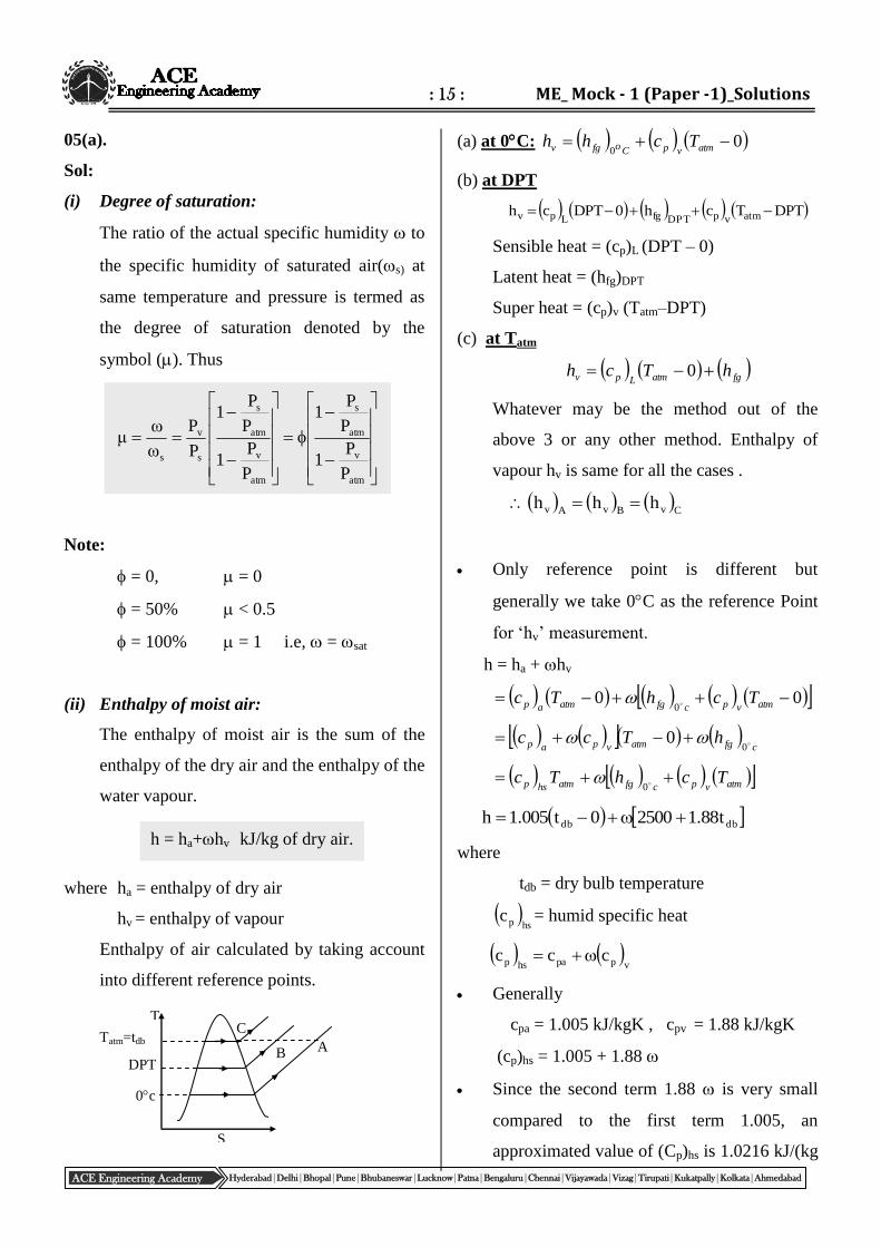
Enthalpy of air calculated by taking account
into different reference points.
(a) at 0C: 00
atmvpCofgv Tchh
(b) at DPT
DPTTch0DPTch atmvpDPTfgLpv
Sensible heat = (cp)L (DPT – 0)
Latent heat = (hfg)DPT
Super heat = (cp)v (Tatm–DPT)
(c) at Tatm
fgatmLpv hTch 0
Whatever may be the method out of the
above 3 or any other method. Enthalpy of
vapour hv is same for all the cases .
CvBvAv hhh
Only reference point is different but
generally we take 0C as the reference Point
for ‘hv’ measurement.
h = ha + hv
000
atmvpcfgatmap TchTc
cfgatmvpap hTcc 0
0
atmvpcfgatmhsp TchTc 0
dbdb t88.125000t005.1h
where
tdb = dry bulb temperature
hspc = humid specific heat
vppahsp ccc
Generally
cpa = 1.005 kJ/kgK , cpv = 1.88 kJ/kgK
(cp)hs = 1.005 + 1.88
Since the second term 1.88 is very small
compared to the first term 1.005, an
approximated value of (Cp)hs is 1.0216 kJ/(kg
T
S
A B
C
DPT
Tatm=tdb
0c
: 16 : ESE - 2019 Main Test Series
ACE Engineering Academy Hyderabad|Delhi|Bhopal|Pune|Bhubaneswar|Lucknow|Patna|Bengaluru|Chennai|Vijayawada|Vizag|Tirupati|Kukatpally|Kolkata|Ahmedabad
dry air K) may be taken for all practical
purposes in air-conditioning calculations.
(iii) Wet bulb depression (W.B.D):
It is the difference between dry bulb
temperature and wet bulb temperature at any
point. The wet bulb depression indicates
relative humidity of the air.
(W.B.D) = DBT – WBT
WBD is maximum when = 0
WBD = 0 when = 100% i.e. DBT = WBT
05(b).
Sol: The properties of steam at entry to the
condenser
h1 = hf + x hfg
= 191.83 + 0.8 (2584.6 – 191.830
= 2225.8 kJ/kg
s1 = sf + x sfg
= 0.6493 + 0.85 (8.1501 – 0.6493)
= 7.025 kJ/kgK
The properties of condensate at exit
h2 = hf at 0.1 bar = 191.83 kJ/kg
s2 = sf at 0.1 bar = 0.6493 kJ/kg
Entropy change of condensate = s2 – s1
= 0.6493 – 7.025 = –6.38 kJ/kgK
Entropy change of cooling water = 27327
hh 21
kgK/kJ78.6300
83.1918.2225
Net increase in entropy = 6.78 – 6.38
= 0.4 kJ/kgK
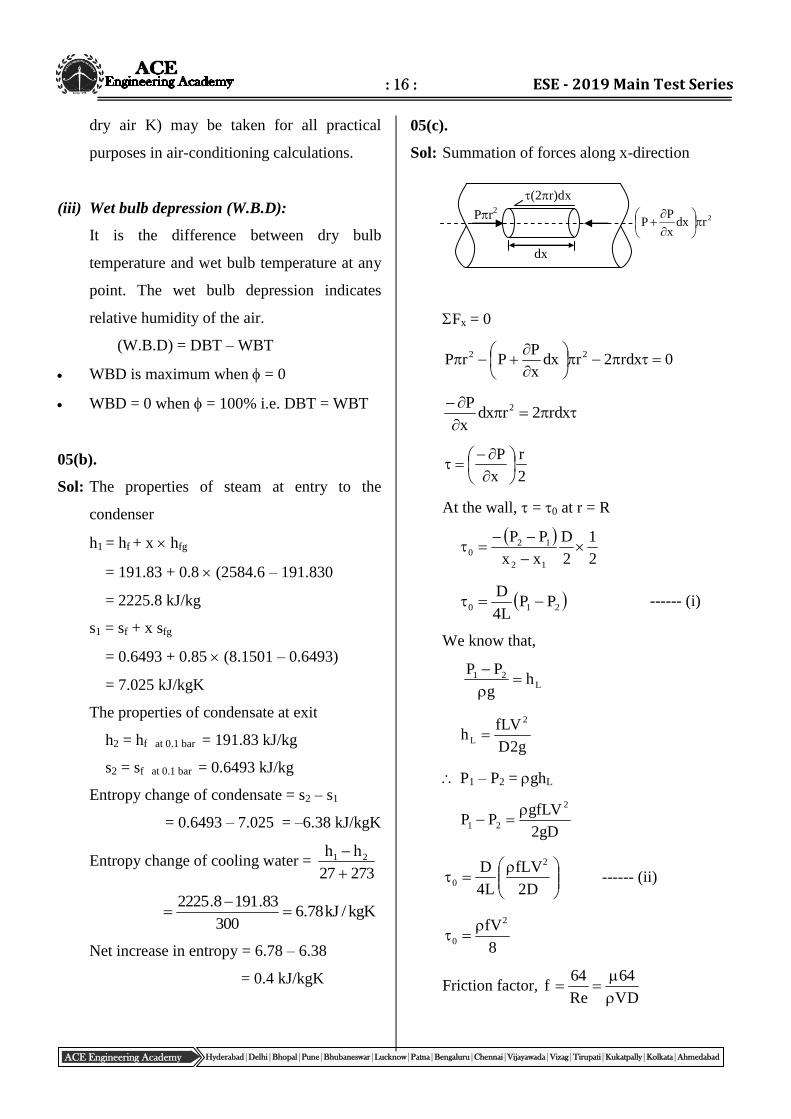
05(c).
Sol: Summation of forces along x-direction
Fx = 0
0rdx2rdxx
PPrP 22
rdx2rdx
x
P 2
2
r
x
P
At the wall, = 0 at r = R
2
1
2
D
xx
PP
12
120
210 PPL4
D ------ (i)
We know that,
L21 h
g
PP
g2D
fLVh
2
L
P1 – P2 = ghL
gD2
gfLVPP
2
21
D2
fLV
L4
D 2
0 ------ (ii)
8
fV2
0
Friction factor, VD
64
Re
64f
dx
(2r)dx
Pr2 2rdx
x
PP
: 17 : ME_ Mock - 1 (Paper -1)_Solutions
ACE Engineering Academy Hyderabad|Delhi|Bhopal|Pune|Bhubaneswar|Lucknow|Patna|Bengaluru|Chennai|Vijayawada|Vizag|Tirupati|Kukatpally|Kolkata|Ahmedabad
r r1
r2
Ceramic layer
Interface
Ts=45C
VD
64
8
V2
0
D
V80
0 will be maximum when V is maximum for
given and D.
Reynolds number,
VDRe
Remax = 2000
VD2000
D
2000V
D
2000
D
80
2
2
0D
16000
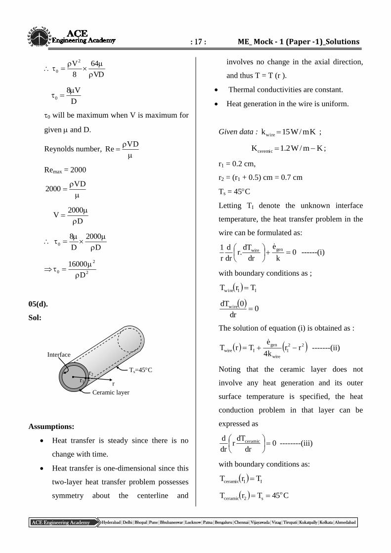
05(d).
Sol:
Assumptions:
Heat transfer is steady since there is no
change with time.
Heat transfer is one-dimensional since this
two-layer heat transfer problem possesses
symmetry about the centerline and
involves no change in the axial direction,
and thus T = T (r ).
Thermal conductivities are constant.
Heat generation in the wire is uniform.
Given data : Km/W15kwire ;
Km/W2.1Kceremic ;
r1 = 0.2 cm,
r2 = (r1 + 0.5) cm = 0.7 cm
Ts = 45C
Letting TI denote the unknown interface
temperature, the heat transfer problem in the
wire can be formulated as:
0k
e
dr
dT.r
dr
d
r
1 genwire
------(i)
with boundary conditions as ;
I1wire TrT
0dr
0dTwire
The solution of equation (i) is obtained as :
22
1
wire
gen
Iwire rrk4
eTrT
-------(ii)
Noting that the ceramic layer does not
involve any heat generation and its outer
surface temperature is specified, the heat
conduction problem in that layer can be
expressed as
0dr
dTr
dr
d ceramic
--------(iii)
with boundary conditions as:
I1ceramic TrT
C45TrT o
s2ceramic
: 18 : ESE - 2019 Main Test Series
ACE Engineering Academy Hyderabad|Delhi|Bhopal|Pune|Bhubaneswar|Lucknow|Patna|Bengaluru|Chennai|Vijayawada|Vizag|Tirupati|Kukatpally|Kolkata|Ahmedabad
Its solution is determined to be
1Is
12
1ceramic TTT
r/rn
r/rnrT
...........(iv)
We have already utilized the first interface
condition by setting the wire and ceramic
layer temperatures equal to TI at the interface
r = r1. The interface temperature TI is
determined from the second interface
condition that the heat flux in the wire and
the ceramic layer at r = r1 must be the same:
dr
rdTk
dr
rdTk 1ceramic
ceramic1wire
wire
112
1sceramic
1gen
r
1
r/rn
TTk
2
re
Solving for TI and substituting the given
values, the interface temperature is
determined to be
s
1
2
ceramic
2
1gen
1 Tr
rn
k2
reT
C4.149C45m002.0
m007.0n
Km/W2.12
m002.0m/W1050 oo
236
Knowing the interface temperature, the
temperature at the centerline (r = 0) is
obtained by substituting the known quantities
into equation (i)
wire
2
1gen
Iwirek4
reT0T
C7.152Km/W154
m002.0m/W1050C4.149 o
236o
Thus the temperature of the centerline will be
slightly above the interface temperature.
05(e).
Sol: Steam must be separated from mixture before
it leaves the drum. Any moisture carried with
steam to super heater tubes contains
dissolved salts. In the superheater water is
evaporated and salts remain deposited on the
inner surface of the tube to form a scale
which is difficult to remove. This scale
reduces the rate of heat absorption ultimately
leading to the failure of super heater tubes by
over heating and rapture. The super heater
tubes are exposed to highest steam pressure
and temperature on inside and maximum gas
temperature on the outside.
No vapour bubble should flow along with
saturated water from the drum to the down
comers. This will reduce the density
difference and the pressure head for natural
circulation. The bubbles tending to flow
upward may also impedance the flow in
down comer and thus affect natural
circulation.
06(a).
Sol: Initial angular velocity of the flywheel
60
30002
60
N2 11
= 314.2 rad/s
Initial available energy or exergy of the
flywheel
2
1initial I2
1E.K
22.31454.0
= 2.66104 Nm = 26.6 kJ
: 19 : ME_ Mock - 1 (Paper -1)_Solutions
ACE Engineering Academy Hyderabad|Delhi|Bhopal|Pune|Bhubaneswar|Lucknow|Patna|Bengaluru|Chennai|Vijayawada|Vizag|Tirupati|Kukatpally|Kolkata|Ahmedabad
When this K.E is dissipated as frictional heat,
if t is the temperature rise of the bearing,
we have
Water equivalent of the bearings Rise in
temperature = 26.6 kJ
C19.3187.42
6.26t o
Final temperature of the bearings,
tf = 15 + 3.19 = 18.19C
The maximum amount of energy which may
be returned to the flywheel as high grade
energy is
dTT
2881187.42.E.A
19.291
288
288
19.291ln28828819.291187.42
= 0.1459 kJ
The amount of energy rendered unavailable
is
U.E. = (A.E.)initial – (A.E.)returnable as high grade energy
= 26.6 – 0.1459
= 26.4541 kJ
Since the amount of energy returnable to the
flywheel is 0.146 kJ, if 2 is the final angular
velocity and the flywheel is set in motion
with this energy, then
2
2
3 54.02
110146.0
8.54027.0
1462
2
2 = 23.246 rad/s
If N2 is the final RPM of the flywheel
60
N2246.23 2
2
2
60246.23N2
= 222 RPM
06(b).
Sol:
981V
V1r
c
s
Consider the process 1-2:
67.219rp
p 4.1
1
2
p2 = 21.671.03105 = 22.3210
5 N/m
2
= 22.32 bar
1
1
2 rT
T = 90.4
= 2.408
T2 = 308 2.408 = 741.6 K = 468.6C
Consider the process 2-3:
p3 = p2 = 22.32 105 N/m
2 = 22.32 bar
T3 = 1773 K = 1500C
Consider the process 3-4:
1
e
4
3 rT
T
6.741
1773
T
TT
2
3c = 2.39
764.3391.2
9
r
rr
c
e
7.1T
T
4
3
7.1
TT 3
4 = 7.1
1773 = 1042.9 K = 769.9C
V
4
3
1
2 P
: 20 : ESE - 2019 Main Test Series
ACE Engineering Academy Hyderabad|Delhi|Bhopal|Pune|Bhubaneswar|Lucknow|Patna|Bengaluru|Chennai|Vijayawada|Vizag|Tirupati|Kukatpally|Kolkata|Ahmedabad
e
4
3 rp
p = 3.764
1.4 = 6.396
396.6
1032.22
396.6
pp
5
34
= 3.49105 N/m
2 = 3.49 bar
addedHeat
outputWorkCycle =
addedHeat
rejectedHeat1
32
14
q
q1
q4-1 = cv (T4 – T1)
= 0.717(1042.9 – 308) = 526.9 kJ/kg
q2-3 = cp (T3 – T2)
= 1.004(1773 – 741.6)
= 1035.5 kJ/kg
4912.05.1035
9.5261Cycle = 49.12%
Work output = q2-3 – q4-1
= 1035.5 – 526.9
= 508.6 kJ/kg
Power output = Work output am
2
N
RT
Vpm
1
11a
R = cp – cv = 0.287 kJ/kg K
V1 = Vs + Vc = sV
8
9
Ld4
6V 2
s
= 1210
46 2
= 5654.8 sec = 5.6510–3
m3
8
91065.5V 3
1 = 6.3610–3
m3
2308287
301036.61003.1m
35
a
= 0.111 kg/s
Power output = 508.6 0.111 = 56.45 kW
06(c).
Sol: Given data,
Dm = 55 cm, h = 9 cm,
N = 9000 rpm, T = 85%,
T01 = 345 K, P01 = 1.7 bar,
= 1.72 kg/m3, = 18
fAVm = Dm hVf
09.055.072.1
45Vf
= 168.2 m/s
60
NDuu m
21
= 259.2 m/s
Velocity triangles for the axial compressor
stage are shown below.
The work done per stage is given by
W = cp (T02 – T01)
= Wf u Vf (tan1 – tan2) ------(i)
where,
Wf = work done factor
Vf = velocity flow (axial velocity)
1 & 2 = blade angles at inlet and exit
1f
11f11
V
tanVutan
2.168
28tan2.1682.259tan 1
1 = 45.3
1 – 2 = 18
2 = 45.3 – 18 = 27.3
From eq. (i)
V2
u1 = u2
1 1
2
1rV Vf1 = Vf2
2
2rV
V1
: 21 : ME_ Mock - 1 (Paper -1)_Solutions
ACE Engineering Academy Hyderabad|Delhi|Bhopal|Pune|Bhubaneswar|Lucknow|Patna|Bengaluru|Chennai|Vijayawada|Vizag|Tirupati|Kukatpally|Kolkata|Ahmedabad
1.005 103 (T02 – T01) = 0.88 259.2
168.2 (tan 45.3 – tan 273)
T02 – T01 = 18.9C
Power = 0102p TTcmWm
= 45 1.005 (18.9)
= 853.5 kW
The isentropic compressor efficiency is given
by
0102
0120c
TT
TT
T02 = T01 +c (T02 – T01)
= 345 + 0.85 18.9 = 361.1C
1
01
20
01
02
T
T
P
P
4.0
4.1
345
1.361
= 1.173
07(a).
Sol:
Let total pressure be P;
For rectangle, A1 = 21 = 2 m2
1x = (9 + 0.5) = 9.5 m
P1 = gA1 1x = 1000 9.8129.5
= 186390 N
= 186.39 kN
Let P1 acts at 1h ,
1h =
xA
Ix G =
5.912
12
12
5.9
3
m51.9h1
For 2 triangles, A2 = 122
1 = 1 m
2
3
19x2 = 9.33 m
P2 = 22xgA = 10009.8119.33
= 91.527 kN
Let P2 be acting at ,h 2
2h = 22
G
2xA
Ix
33.91
36
12
33.9
3
2h = 9.336 m
Total pressure P = P1 + P2 = 186.39 + 91.527
P = 277.92 kN
Centre of pressure h = 21
2211
PP
hPhP
= 527.9139.186
336.9527.9151.939.186
= 9.45 m
Now take the moments about the hinge (a)
P0.45 = F 1
277.92 0.45 = F
F = 125.064 kN
where F = Force to be applied at the bottom
of the gate.
If the tank is filled half only:
Let total pressure be P;
For rectangle, A1 = 21 = 2m2
1x = (4 + 0.5) = 4.5 m
P1 = gA1 1x = 1000 9.8124.5
h x
10m
Fig: front view
10m
10m
4m
2m
1 2 1
Fig: side view
2 a
: 22 : ESE - 2019 Main Test Series
ACE Engineering Academy Hyderabad|Delhi|Bhopal|Pune|Bhubaneswar|Lucknow|Patna|Bengaluru|Chennai|Vijayawada|Vizag|Tirupati|Kukatpally|Kolkata|Ahmedabad
= 88.29 kN
Let P1 acts at 1h ,
1h = xA
Ix G =
5.412
12
12
5.4
3
m518.4h1
For 2 triangles, A2 = 122
1 = 1 m
2
3
14x 2 = 4.33 m
P2 = 22xgA = 10009.8114.33
= 42.51 kN
Let P2 be acting at ,h 2
2h = 22
G
2xA
Ix
33.41
36
12
33.4
3
2h = 4.34 m
Total pressure P = P1 + P2 = 88.29 + 42.51
P = 130.8 kN
Centre of pressure h = 21
2211
PP
hPhP
= 8.130
34.451.42518.42.88
= 4.46 m
Now take the moments about the hinge (a)
P0.46 = F 1
130.8 0.46 = F
F = 60.168 kN
where F = Force to be applied at the bottom
of the gate.
Hence, if the water is filled half of the tank,
force applied at the bottom of the tank is
reduced nearly to half.
07(b).
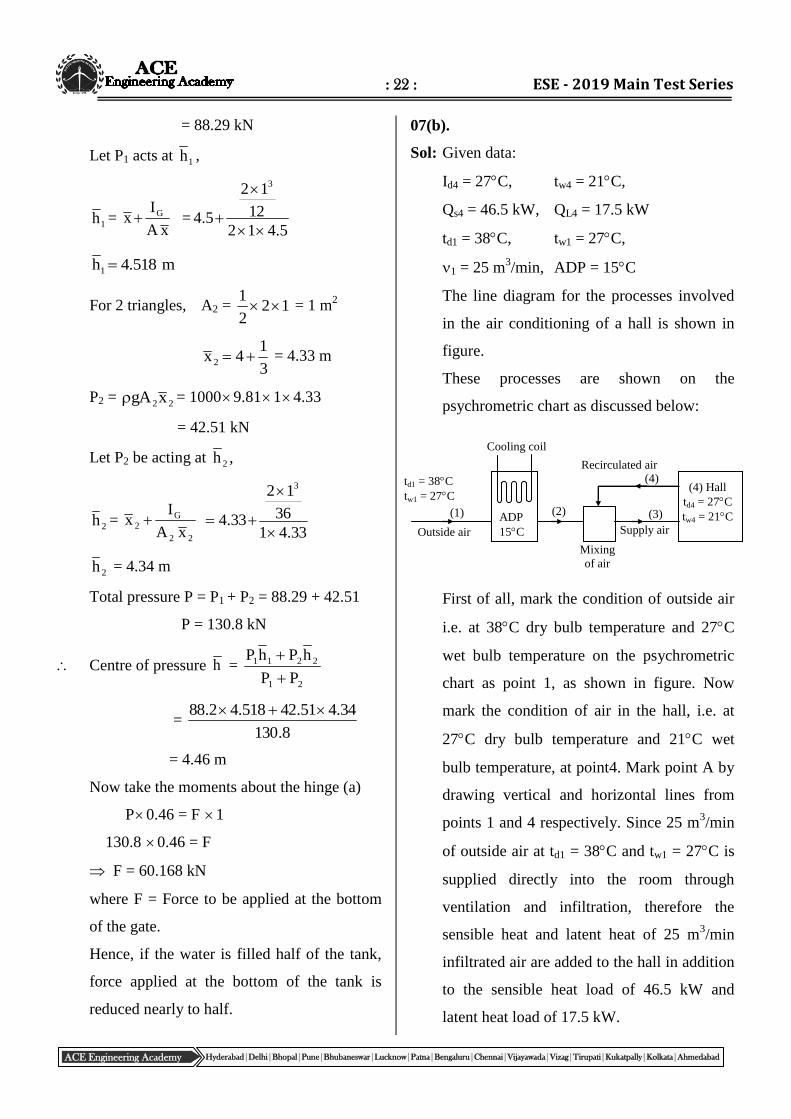
Sol: Given data:
Id4 = 27C, tw4 = 21C,
Qs4 = 46.5 kW, QL4 = 17.5 kW
td1 = 38C, tw1 = 27C,
1 = 25 m3/min, ADP = 15C
The line diagram for the processes involved
in the air conditioning of a hall is shown in
figure.
These processes are shown on the
psychrometric chart as discussed below:
First of all, mark the condition of outside air
i.e. at 38C dry bulb temperature and 27C
wet bulb temperature on the psychrometric
chart as point 1, as shown in figure. Now
mark the condition of air in the hall, i.e. at
27C dry bulb temperature and 21C wet
bulb temperature, at point4. Mark point A by
drawing vertical and horizontal lines from
points 1 and 4 respectively. Since 25 m3/min
of outside air at td1 = 38C and tw1 = 27C is
supplied directly into the room through
ventilation and infiltration, therefore the
sensible heat and latent heat of 25 m3/min
infiltrated air are added to the hall in addition
to the sensible heat load of 46.5 kW and
latent heat load of 17.5 kW.
(1)
td1 = 38C
tw1 = 27C
Outside air
ADP
15C
(2)
Mixing
of air
Supply air
(3)
(4) Recirculated air
(4) Hall
td4 = 27C
tw4 = 21C
Cooling coil
: 23 : ME_ Mock - 1 (Paper -1)_Solutions
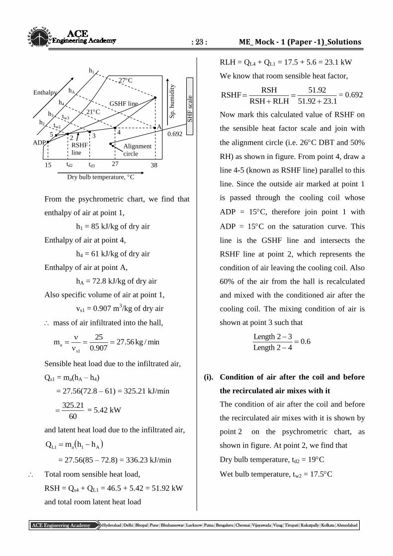
ACE Engineering Academy Hyderabad|Delhi|Bhopal|Pune|Bhubaneswar|Lucknow|Patna|Bengaluru|Chennai|Vijayawada|Vizag|Tirupati|Kukatpally|Kolkata|Ahmedabad
ADP
15 td2 td3 27
Alignment
circle
38
A
RSHF
line
2 3
4
27C
21C
GSHF line
5
tw2
tw3
h2
h3
h4
hA
h1
0.692
SH
F s
cale
Sp
. h
um
idit
y
Dry bulb temperature, C
Enthalpy
From the psychrometric chart, we find that
enthalpy of air at point 1,
h1 = 85 kJ/kg of dry air
Enthalpy of air at point 4,
h4 = 61 kJ/kg of dry air
Enthalpy of air at point A,
hA = 72.8 kJ/kg of dry air
Also specific volume of air at point 1,
vs1 = 0.907 m3/kg of dry air
mass of air infiltrated into the hall,
min/kg56.27907.0
25m
1s
a
Sensible heat load due to the infiltrated air,
Qs1 = ma(hA – h4)
= 27.56(72.8 – 61) = 325.21 kJ/min
60
21.325 = 5.42 kW
and latent heat load due to the infiltrated air,
A1a1L hhmQ
= 27.56(85 – 72.8) = 336.23 kJ/min
Total room sensible heat load,
RSH = Qs4 + QL1 = 46.5 + 5.42 = 51.92 kW
and total room latent heat load
RLH = QL4 + QL1 = 17.5 + 5.6 = 23.1 kW
We know that room sensible heat factor,
1.2392.51
92.51
RLHRSH
RSHRSHF
= 0.692
Now mark this calculated value of RSHF on
the sensible heat factor scale and join with
the alignment circle (i.e. 26C DBT and 50%
RH) as shown in figure. From point 4, draw a
line 4-5 (known as RSHF line) parallel to this
line. Since the outside air marked at point 1
is passed through the cooling coil whose
ADP = 15C, therefore join point 1 with
ADP = 15C on the saturation curve. This
line is the GSHF line and intersects the
RSHF line at point 2, which represents the
condition of air leaving the cooling coil. Also
60% of the air from the hall is recalculated
and mixed with the conditioned air after the
cooling coil. The mixing condition of air is
shown at point 3 such that
6.042Length
32Length
(i). Condition of air after the coil and before
the recirculated air mixes with it
The condition of air after the coil and before
the recirculated air mixes with it is shown by
point 2 on the psychrometric chart, as
shown in figure. At point 2, we find that
Dry bulb temperature, td2 = 19C
Wet bulb temperature, tw2 = 17.5C
: 24 : ESE - 2019 Main Test Series
ACE Engineering Academy Hyderabad|Delhi|Bhopal|Pune|Bhubaneswar|Lucknow|Patna|Bengaluru|Chennai|Vijayawada|Vizag|Tirupati|Kukatpally|Kolkata|Ahmedabad
(ii). Condition of air entering the hall, i.e. after
mixing with recirculated air
The condition of air entering the hall, i.e.
after mixing with recirculated air, is shown
by point 3 on the psychrometric chart, as
shown in figure. At point 3, we find that
Dry bulb temperature, td3 = 24C
Wet bulb temperature, tw3 = 19.8C
(iii). Mass of fresh air entering the cooler
The mass of fresh air passing through the
cooling coil to take up the sensible and latent
heat of the hall is given by
24
Fhh
removedheatTotalm
=
24 hh
RLHRSH
4961
1.2392.51
= 6.25 kg/s = 6.2560 = 375 kg/min
(From psychrometric chart, h2 = 49 kJ/kg of
dry air)
(iv). By pass factor of the cooling coil
We know that by-pass factor of the cooling
coil,
ADPt
ADPtBPF
1d
2d
=
1538
1519
= 0.174
(v). Refrigerating load on the cooling coil:
We know that the refrigerating load on the
cooling coil
= mF(h1 – h2)
= 375(85 – 49) = 13500 kJ/min
210
13500 = 64.3 TR
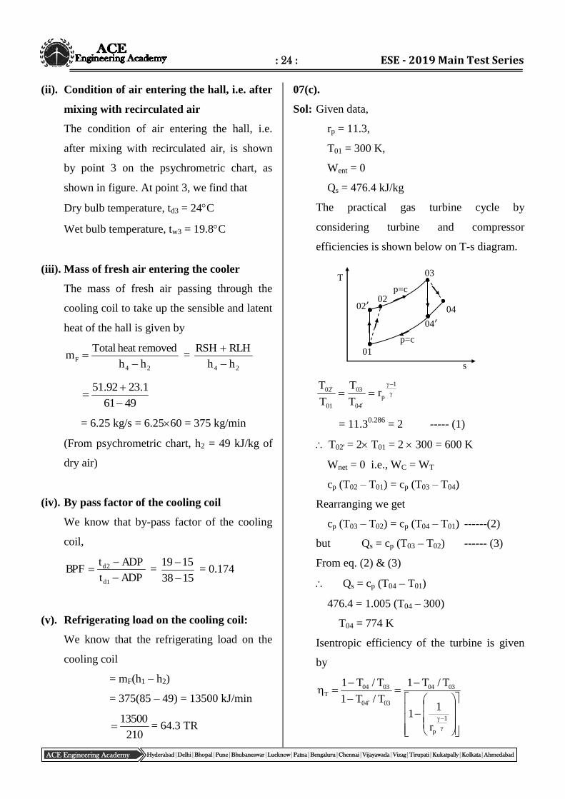
07(c).
Sol: Given data,
rp = 11.3,
T01 = 300 K,
Went = 0
Qs = 476.4 kJ/kg
The practical gas turbine cycle by
considering turbine and compressor
efficiencies is shown below on T-s diagram.
1
p
40
03
01
20 rT
T
T
T
= 11.30.286
= 2 ----- (1)
T02 = 2 T01 = 2 300 = 600 K
Wnet = 0 i.e., WC = WT
cp (T02 – T01) = cp (T03 – T04)
Rearranging we get
cp (T03 – T02) = cp (T04 – T01) ------(2)
but Qs = cp (T03 – T02) ------ (3)
From eq. (2) & (3)
Qs = cp (T04 – T01)
476.4 = 1.005 (T04 – 300)
T04 = 774 K
Isentropic efficiency of the turbine is given
by
1
p
0304
0340
0304T
r
11
T/T1
T/T1
T/T1
02
s
T
02ʹ
03
04
04ʹ
01
p=c
p=c
: 25 : ME_ Mock - 1 (Paper -1)_Solutions
ACE Engineering Academy Hyderabad|Delhi|Bhopal|Pune|Bhubaneswar|Lucknow|Patna|Bengaluru|Chennai|Vijayawada|Vizag|Tirupati|Kukatpally|Kolkata|Ahmedabad
i.e.,
2
11
774
T1
71.0
04
2
71.01
774
T03
T03 = 1200 K
From equation (1).
T02 – T01 = T03 – T04
T02 – 300 = 1200 – 774
T02 = 726 K
The isentropic compression efficiency is
given by
0102
0120c
TT
TT
704.0
300726
300600
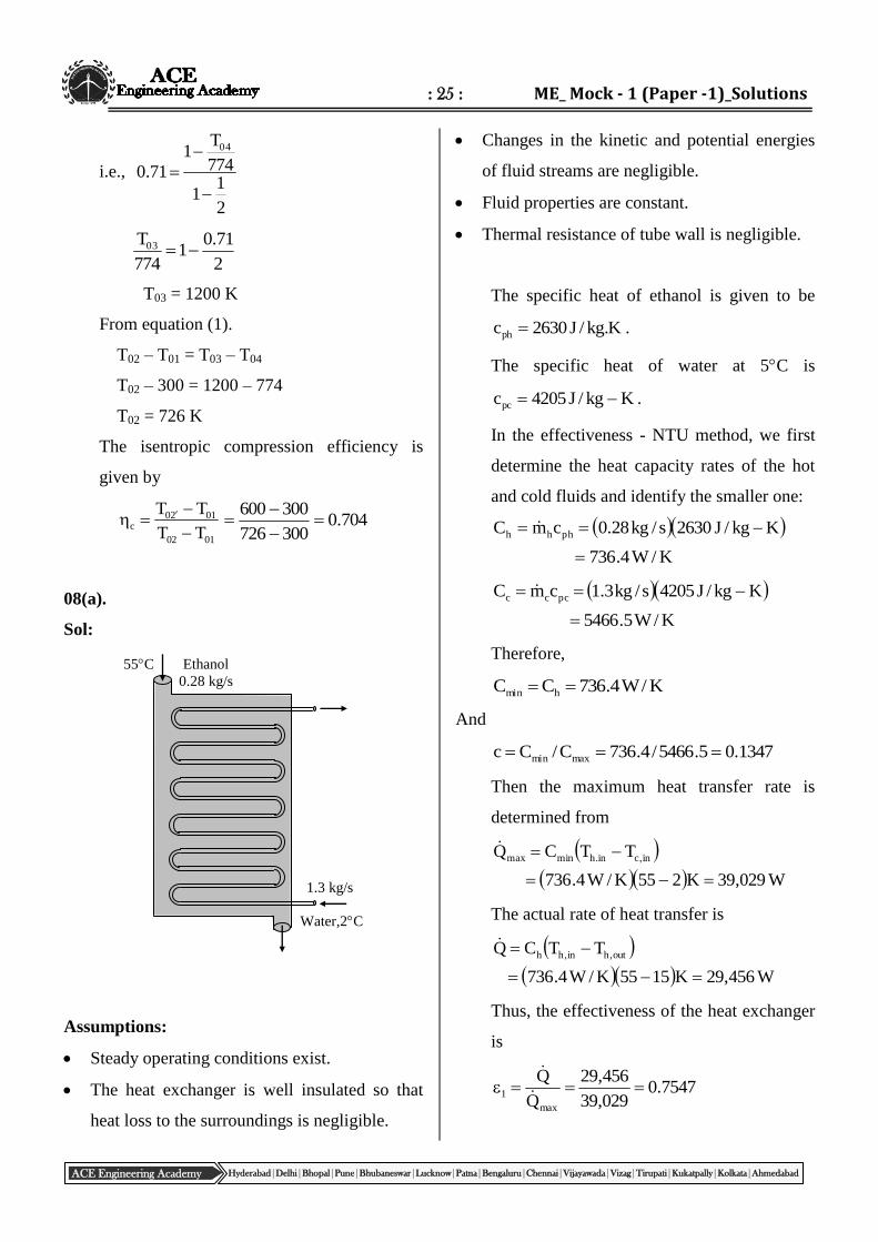
08(a).
Sol:
Assumptions:
Steady operating conditions exist.
The heat exchanger is well insulated so that
heat loss to the surroundings is negligible.
Changes in the kinetic and potential energies
of fluid streams are negligible.
Fluid properties are constant.
Thermal resistance of tube wall is negligible.
The specific heat of ethanol is given to be
K.kg/J2630cph .
The specific heat of water at 5C is
Kkg/J4205cpc .
In the effectiveness - NTU method, we first
determine the heat capacity rates of the hot
and cold fluids and identify the smaller one:
K/W4.736
Kkg/J2630s/kg28.0cmC phhh
K/W5.5466
Kkg/J4205s/kg3.1cmC pccc
Therefore,
K/W4.736CC hmin
And
1347.05.5466/4.736C/Cc maxmin
Then the maximum heat transfer rate is
determined from
W029,39K255K/W4.736
TTCQ in,cin.hminmax
The actual rate of heat transfer is
W456,29K1555K/W4.736
TTCQ out,hin,hh
Thus, the effectiveness of the heat exchanger
is
7547.0029,39
456,29
Q
Q
max
1
Water,2C
1.3 kg/s
55C Ethanol
0.28 kg/s
: 26 : ESE - 2019 Main Test Series
ACE Engineering Academy Hyderabad|Delhi|Bhopal|Pune|Bhubaneswar|Lucknow|Patna|Bengaluru|Chennai|Vijayawada|Vizag|Tirupati|Kukatpally|Kolkata|Ahmedabad
For this one - shell pass heat exchanger,
knowing the effectiveness (), the NTU of
this heat exchanger can be determined from
the given appropriate relation.
2
1
2
1
21
c1c1/2
c1c1/2n
c1
1NTU
2
2
2 1347.011347.017547.0/2
1347.011347.017547.0/2n
1347.01
1
= 1.592
Note that for this one-shell pass heat
exchanger 1 and NTUNTU1 .
Then the number of tube passes can be
determined using
592.1C
nDLU
C
UANTU
minmin
s
Thus,
passestube1285.11
m3m015.0K.m/W700
592.1K/W4.736
DLU
NTUCn
2
min
08(b).
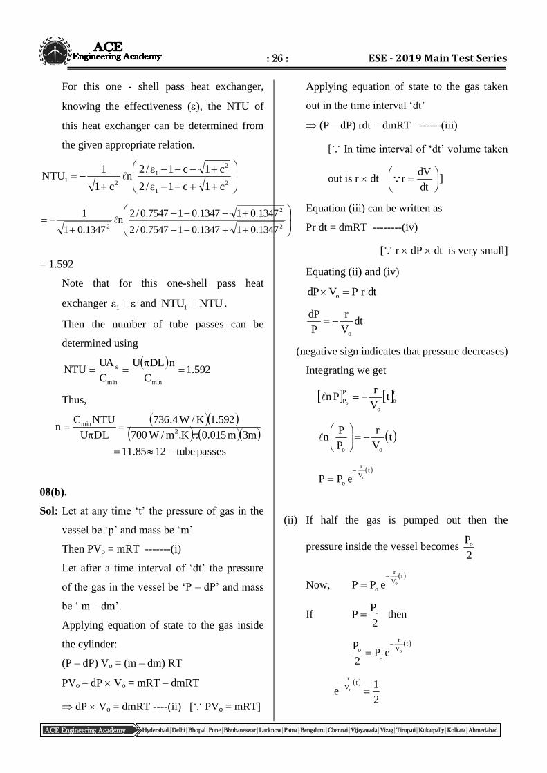
Sol: Let at any time ‘t’ the pressure of gas in the
vessel be ‘p’ and mass be ‘m’
Then PVo = mRT -------(i)
Let after a time interval of ‘dt’ the pressure
of the gas in the vessel be ‘P – dP’ and mass
be ‘ m – dm’.
Applying equation of state to the gas inside
the cylinder:
(P – dP) Vo = (m – dm) RT
PVo – dP Vo = mRT – dmRT
dP Vo = dmRT ----(ii) [∵ PVo = mRT]
Applying equation of state to the gas taken
out in the time interval ‘dt’
(P – dP) rdt = dmRT ------(iii)
[∵ In time interval of ‘dt’ volume taken
out is r dt
dt
dVr ]
Equation (iii) can be written as
Pr dt = dmRT --------(iv)
[∵ r dP dt is very small]
Equating (ii) and (iv)
dtrPVdP o
dtV
r
P
dP
o
(negative sign indicates that pressure decreases)
Integrating we get
too
P
Pt
V
rPn
o
tV
r
P
Pn
oo
t
V
r
ooePP
(ii) If half the gas is pumped out then the
pressure inside the vessel becomes 2
Po
Now, t
V
r
ooePP
If 2
PP o then
t
V
r
oo oeP
2
P
2
1e
tV
r
o
: 27 : ME_ Mock - 1 (Paper -1)_Solutions
ACE Engineering Academy Hyderabad|Delhi|Bhopal|Pune|Bhubaneswar|Lucknow|Patna|Bengaluru|Chennai|Vijayawada|Vizag|Tirupati|Kukatpally|Kolkata|Ahmedabad
2et
V
r
o
2nV
tr
o
2nr
Vt o
08(c)(i).
Sol: The main difficulties in the development of
tidal energy are as follows.
Fluctuation in the output power due to
variations in the tidal ranges is its major
drawback.
The range of tidal energy is restricted to a
small value.
The equipments used for tidal energy may
get corroded due to high corrosiveness of sea
water.
The turbines have to work on a wide range of
head vibrations which reduces the efficiency
of the plant.
The power cannot be produced continuously
due to difference in the level of sea inland
basin.
The planning of daily load sharing in a grid is
difficult as the power cycle occurrence is not
constant.
The installation of the plant is quite difficult
in sea or in estuary.
It obstructs the natural habitat of fishing.
It also effects the navigation.
It is comparatively not as much economical
as all sources of energy.
08(c)(ii).
Sol: Given data:
Total number of power generators = 24
Maximum head (H) = 13.5 M
Total time (t) = 26 hours per day
= 12 hours = 123600 sec
Efficiency () = 93% = 0.93
Total power of 24 generators
= 24 10 = 240 MW
P = 2.4 108 W ( 1 MW = 10
6 W)
Average discharge,
t
VQ
360012
VQ
Power at any instant,
75
HQP
93.0360012
5.131025v104.2 8
2.4108123600 = v102513.50.93
93.05.131025
360012104.2v
8
v = 8.05108 m
3
Basin capacity = 8.05108 m
3
Annual energy production
= P t No. of days in a year
= 2.4 108 12 3600 365 0.93
= 3.52 1015
J