Embed Size (px)
Citation preview

AFLD API 614 SeriesInline Duplex Filters – 232 PSI • up to 630 GPM
HYDRAULIC AND LUBE OIL FILTERS
Features• Filter series designed to meet the requirements of API 614 for lube oil and other applications.
• Models are available in carbon and stainless steel versions.
• Transfer valve internal components of stainless steel.
• ANSI flange connections standard
• Inlet and outlet connections are located on the same side of the transfer valve.
• Transfer valve and pressure equalization line allow easy changeover between filter housings without costly system shutdown.
• Air bleed line and drain line available.
• ASME coded with ASME-stamp , CRN, AS1210, GOST available
• 2.2 material certificate standard
• 3.1 B material certificate optional
Hydraulic SymbolA
B
A
B
FI FI
Applications
Technical DetailsMounting Method Floor mounted brackets
(Filters must not be used as pipe support)
Port Connection
122/123232/233542/543852/8531322/13232702/2703
1”1.5”2”3”4”6”
ANSI 150# Flanges*ANSI 150# Flanges*ANSI 150# Flanges*ANSI 150# FlangesANSI 150# FlangesANSI 150# Flanges
*(300# and 600# available upon request)
Flow Direction Inlet: Front top Outlet: Front Bottom
Construction Materials (Transfer valve balls and spindle, stainless steel)
122, 232, 542, 852, 1322, 2702 - Carbon Steel 123, 233, 543, 853, 1323, 2703 - Stainless Steel (ASTM 240 Type 316L)
Flow Capacity @ 32 CSt
122/123232/233542/543852/8531322/13232702/2703
53 gpm95 gpm221 gpm278 gpm304 gpm634 gpm
201 lpm360 lpm837 lpm1052 lpm1151 lpm2400 lpm
Housing Pressure Rating
Max.OperatingPressureProof PressureFatigue PressureBurst Pressure
232 psi (16 bar)590 psi (40 bar)Contact HYDAC officeContact HYDAC office*
*other pressures available upon request
Element Collapse Pressure Rating
ON/PO 250 psid (17 bar)
Fluid Temperature Range -22° to 212°F (-30° to 100°C)
Fluid Compatability
Compatible with all petroleum oils and synthetic fluids rated for use with Fluoroelastomer or Ethylene Propylene seals. Contact HYDAC for information on special housing and element constructions available for use with water glycols, oil/water emulsions, and HWBF.
Optional: Indicator Trip Pressure
∆P = 29 psid (2 bar) -10%
Off Shore PowerGeneration
Industrial

Model CodeAFLD ON/PO 1322 C A 5 10 W 1 . X / Z U 150 V DH
Filter TypeElement Media ON/PO = Optimicron® Power with STAT-FREESize 122/123, 232/233, 542/543, 852/853, 1322/1323, 2702/2703Operating Pressure C = 232 psi (16 bar)Type of Change Over Valve A = Ball ValveType of Connection 1 = 1” ANSI 150# Flange (sizes 122/123)* 2 = 1.5” ANSI 150# Flange (sizes 232/233)* 3 = 2” ANSI 150# Flange (sizes 542/543)* 4 = 3” ANSI 150# Flange (sizes 852/853) 5 = 4” ANSI 150# Flange (sizes 1322/1323) 7 = 6” ANSI 150# Flange (sizes 2702/2703) *(300# and 600# available upon request)
Filtration Rating (microns) 10 = ON/PO Type of ∆P Clogging Indicator A = plugged indicator port Indicator Model B = visual (auto-reset) VM...B C = electric switch VM...C D = electric switch and light VM...D/L (lamp voltage selected from supplementary section)
W = no indicator port (standard) (For details and additional indicator options, see pages 213 - 242)Type Code 1Modification Number (latest version always supplied)
Country of Installation (omit) = (non coded) U = ASME Coded with “ASME” Stamp (ZU for ASME-Stamp with documentation) Z = 2.2 material and pressure test certification (standard)
Flange 150 = 150# ANSI FlangeSeals (omit) = Buna-N (standard) V = Fluoroelastomer (FPM)Bypass Valve Cracking Pressure (omit) = No Bypass (API standard) B3 = 43 psid (3 bar) B6 = 87 psid (6 bar)Supplementary L24 = Lamp for 24 Volts (D-type clogging, indicator only) L48 = Lamp for 48 Volts (D-type clogging, indicator only) L110 = Lamp for 110 Volts (D-type clogging, indicator only) L220 = Lamp for 220 Volts (D-type clogging, indicator only) W = SP - indictor with brass piston (for water base fluids) SO103H = Modification of BN4HC Elements for Phosphate Ester Fluids VKD = Drain piping EM = Air bleed valves DH = Cover Lifting Device
Model Codes Containing RED are non-stock items — Minimum quantities may apply – Contact HYDAC for information and availability
Replacement Element Model Code0850 A 010 ON/PO / V
Size 120, 230, 540, 850, 2600, 2700
Filtration Rating (micron) 10= ON/PO
Element Media ON/PO
Supplementary Details (omit) = standard V = Fluoroelastomer (FPM) seals

Sizing InformationTotal pressure loss through the filter is as follows:
Assembly ∆P = Housing ∆P + Element ∆P
Housing Curve:
Pressure loss through housing is as follows:
Housing ∆P = Housing Curve ∆P x Actual Specific Gravity
0.86
Adjustments must be made for viscosity & specific gravity of the fluid to be used! (see sizing section on page 21)
Element K Factors∆P Elements = Elements (K) Flow Factor x Flow Rate (gpm) x
Actual Viscosity (SUS) x Actual Specific Gravity (From Tables Below) 141 SUS 0.86
Required Element Per HousingHousing Size Element Size Elements per Side
122 / 123 120 1
232 / 233 230 1
542 / 543 540 1
852 / 853 850 1
1322 / 1323 2600 1
2702 / 2703 2700 1
Size...A...ON/PO
10 µm Wgt. (lb)
120 0.075 0.95
230 0.037 1.10
540 0.018 3.50
850 0.008 4.50
2600 0.004 14.0
2700 0.004 20.5
All Element K Factors in psi / gpm.
AFLD 2702/2703 Housing w/ANSI 6” 150# Flange
AFLD 232/233 Housing w/ANSI 1.5” 150# Flange
AFLD 542/543 Housing w/ANSI 2” 150# Flange
AFLD 852/853 Housing w/ANSI 3” 150# Flange
AFLD 1322/1323 Housing w/ANSI 4” 150# Flange
0
0.07
0.14
0.21
0.28
0.350 800 1600 2400 3200
0
1
2
3
4
5
0 170 340 510 680 850
∆p in
bar
∆p in
psi
d
Flow in l/m
Flow in gpm
AFLD 122/123 Housing w/ANSI 1” 150# Flange

Dimensions AFLD 122 / 123 / 232 / 233
Size 122 123 232 233
Weight (lbs.) 122 122 269 269
Dimensions shown are for general information and overall envelope size only. Weights listed are without element. For complete dimensions please contact HYDAC to request a certified print.
Size A B C D E F G H I J K L M N O Connection
122-123 [514] 20.24
[126.8] 4.99
[63.4] 2.49
[200] 7.87
[155] 6.10
[230.8] 9.09
[200] 7.87
[155] 6.10
[229] 9.02
[153.5] 6.04
[96] 3.78
[108] 4.25
[183] 7.20
[79.4] 3.13
[195] 7.68
ANSI 150 lb RF 1”
232-233 [595] 23.43
[190.9] 7.52
[95.5] 3.76
[222] 8.74
[220] 8.66
[326.8] 12.87
[243] 9.57
[220] 8.66
[272] 10.71
[170] 6.69
[121.7] 4.79
[145] 5.71
[227] 8.94
[98.4] 3.87
[205] 8.07
ANSI 150 lb RF 1.5”
Dimensions are in inches/millimeters.
OCLEARANCE
FOR ELEMENTREMOVAL B
A
C
F
Ø N
M12D
EOUTLET
INLET
M16
82.6mmØ 3.25in
G
HJ
I
CLEAN SIDEDRAIN PORT(G 3/4")2 PL
DIRTY SIDEDRAIN PORT(G 3/4")2 PL
VENT PORT(G 1/8")2 PL
DIFFERENTIAL PRESSURECONNECTIONS(G 1/4")2 PL
MTRANSFERVALVE HANDLE TURNRADIUS
K
LVENT PORT(G 3/4")2 PL
PRESSURE EQUALIZATION LINE
22mmØ 0.87in
4 PL
100mm3.94in 20mm
0.79in
100mm3.94in

Dimensions AFLD 542 / 543
Size 542 543
Weight (lbs.) 500 500
Dimensions shown are for general information and overall envelope size only. Weights listed are without element. For complete dimensions please contact HYDAC to request a certified print.
Size Connection
542 / 543 2”
Dimensions are in inches/millimeters.
[14.57]370
CLEARANCE REQUIREDFOR ELEMENT REMOVAL
399.9mm16in
231.9mm9.13in
M16
115.95mm4.56in
234.8mm9.24in
170mm6.69in
653.3mm25.72in
INLET2" ASMEB16.5, 150 LBS. RF
OUTLET2" ASMEB16.5, 150 LBS. RF
22mmØ 0.87in
4 PL
100mm3.94in
20mm0.79in
100mm3.94in
314.5mm12.38in
278.8mm11in 82.6mm
Ø 3.25in
170mm6.69in
M12
259.3mm10.21in
DIFFERENTIAL PRESSURECONNECTIONS(G 1/4")2 PL
131mm5.16in
227mmR8.94inTRANSFERVALVE HANDLE TURNRADIUS
170mm6.69in
VENT PORT(G 3/4")2 PL
PRESSURE EQUALIZATION LINE
120.7mmØ 4.75in
DIRTY SIDEDRAIN PORT(G 3/4")2 PL
CLEAN SIDEDRAIN PORT(G 3/4")2 PL
VENT PORT(G 1/8")2 PL
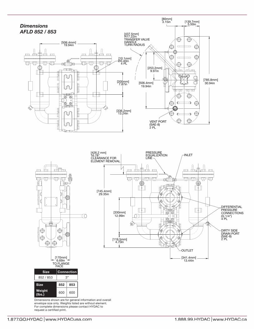
Dimensions AFLD 852 / 853
Size Connection
852 / 853 3”
Size 852 853
Weight (lbs.) 600 600
Dimensions shown are for general information and overall envelope size only. Weights listed are without element. For complete dimensions please contact HYDAC to request a certified print.
[745.4mm]29.35in
[341.4mm]13.44in
[119.5mm]4.70in
[330mm]12.99in
PRESSUREEQUALIZATIONLINE
INLET
OUTLET
DIFFERENTIALPRESSURECONNECTIONS(G 1/4")4 PL
[426.2 mm]16.78"CLEARANCE FORELEMENT REMOVAL
DIRTY SIDEDRAIN PORT(SAE-8)2 PL
[437.5mm]R17.22inTRANSFER VALVEHANDLETURN RADIUS
[253.2mm]9.97in
[139.7mm]5.50in
[785.8mm]30.94in[506.4mm]
19.94in
[80mm]3.15in
VENT PORT(SAE-8)2 PL
[170mm]6.69in
TO FLANGEFACE
[506.4mm]19.94in
[200mm]7.87in
[10.1mm]Ø0.40in
4 PL
[336.2mm]13.24in

Dimensions AFLD 1322 / 1323
Size Connection
1322 / 1323 4”
Size 1322 1323
Weight (lbs.) 700 700
Dimensions shown are for general information and overall envelope size only. Weights listed are without element. For complete dimensions please contact HYDAC to request a certified print.
52.06in[1322.4mm]
[101.6mm]4.00in
[200mm]7.87in
9.84in[250mm]
8.50in[216mm]
[940mm]37.00inCLEARANCE FORELEMENT REMOVAL
PRESSUREEQUALIZATIONLINE
INLET
OUTLET
DIFFERENTIALPRESSURECONNECTIONS(SAE-6)2 PL
DIRTY SIDEDRAIN PORT(SAE-12)2 PL
CLEAN SIDEDRAIN PORT(SAE-12)2 PL
317mmR12.48inTRANSFER VALVEHANDLETURN RADIUS
[294.2mm]11.58in
[958.6mm]37.74in
[588.4mm]23.17in
[175.7mm]6.92in
VENT PORT(SAE-4)2 PL
[266.7mm]10.50in
[266.7mm]10.50in
[22.2mm]Ø 0.88in
8 PL
[266.7mm]10.50in
[266.7mm]10.50in
[873.8mm]34.40in
[130mm]5.12in

© Copyright 2012 HYDAC TECHNOLOGY CORPORATION • Filters • TECH DATA • 1202-1409
Dimensions AFLD 2702 / 2703
Size Connection
2702 / 2703 6”
Size 2702 2703
Weight (lbs.) 820 820
Dimensions shown are for general information and overall envelope size only. Weights listed are without element. For complete dimensions please contact HYDAC to request a certified print.
16.73in425mm
11.81in300mm
37.97in964.5mm
INLET
OUTLET
19.69in[500 mm]CLEARANCE FORELEMENT REMOVAL
R12.48in317mm
TRANSFER VALVEHANDLE
TURN RADIUS
12.85in326.5mm
7.25in184.2mm
R4.33in110mm
PRESSURE EQUALIZATIONVALVE
TURN RADIUS
39.49in1003mm
25.71in653mm
7.48in190mm
PRESSUREEQUALIZATIONVALVE
9.84
in25
0mm
7.48
in19
0mm
25.3
1in
643m
m
0.87
in22
mm
4 P
L
9.39in238.5mm
16.34in415mm
15.06in382.5mm
CLEAN SIDEDRAIN PORT(G 3/4")2 PL
DIRTY SIDEDRAIN PORT(G 3/4")2 PL
VENT PORT(G 3/4")2 PL
DIFFERENTIALPRESSURECONNECTIONS(G 1/4")2 PL