Embed Size (px)
Citation preview
HYDRAULIC AND THERMAL STUDIES ON A CHEVRON TYPE PLATE HEAT EXCHANGER
1Bhupal KUMAR, 2S.N. SINGH*
1Research Scholar, Department of ME, IIT (ISM), Dhanbad, Jharkhand 826004, India
*2Associate Professor, Department of ME, IIT(ISM), Dhanbad. Jharkhand 826004, India
* Corresponding author; E-mail: [email protected]
The present work deals with the experimental study of a single pass U-type
chevron plate heat exchanger using liquid-liquid combination in both the
channels for the range of Reynolds numbers, 800-5900. The influence of
Reynolds number, pumping power and number of plates on the hydraulic and
thermal performance of PHE are presented. Results are predicted for a chevron
angle of β=60o and fixed port size dp =25.4 mm for a different set of plates,
namely, 15, 21 and 27 under two different conditions viz. (i) isothermal and (ii)
non-isothermal. The present results of non-dimensional channel velocity and
Nusselt number are compared with the analytical results of Bossiouny and
Martin [3] and Nusselt number correlation of Wang and Sunden [19]
respectively. At a Reynolds numbers of 3900, enhancement in Nusselt number on
increasing number of plates from 15 to 21 and 21 to 27, is found to be 56% and
19% respectively. Based on experimental data, correlations for Nusselt number
and friction factor are also developed.
Keywords: Plate heat exchanger, flow maldistribution, chevron, pressure drop,
Nusselt number
1. Introduction
Plate heat exchangers, which were initially used for hygienic application such as dairy, brewery,
pharmaceuticals and food processing industries, have now found their applications in the modern industry
also. PHEs have quick response to control operations and possess capability to recover heat from
extremely small temperature differences, thus widening their applications. In plate heat exchangers, the
two plates facing each other have their corrugation lines alignment opposite to one another, so as to
separate and produce cross corrugated flow channels. Gasket is present on one of the two mating surfaces.
The fluid flow in each successive channel is in a direction opposite to the previous one. The cross-
corrugated channel generates a highly turbulent flow, thus increasing the heat transfer even at low
Reynolds number. The pressure drop as well as thermal performance of a plate heat exchanger depends
critically on the distribution of fluid flow and geometrical properties of the chevron plates namely
corrugation angle, area enlargement factor and channel aspect ratio.
Mueller and Chiou [1] presented a review of the problem related to maldistribution. Mulley and
Manglik [2] experimentally investigated the turbulent flow heat transfer and pressure drop in a plate heat
1
exchanger for different corrugation angles. Their analysis is based on the assumption that flow rates are
equal in all the channels. Bassiouny and Martin [3] derived the axial velocity, total pressure drop, flow
distribution in channels and pressure distributions in inlet and outlet conduits of plate heat exchangers.
They also developed a general flow maldistribution characteristic parameter, m2, for inlet and exit port
flows. Giraud et al. [4] experimentally studied the water vaporization inside a channel of a smooth plate-
type heat exchanger at sub-atmospheric pressure. Fang et al. [5] investigated the flow distribution in
manifolds of the heat exchanger. To predict the pressure distribution in headers, they proposed a discrete
mathematical model matching the real physical phenomena. Tereda et al. [6] investigated the port-to-
channel flow maldistribution for a fixed number of plates, and corrugation angle, varying only the port
diameter. Tsai et al. [7] studied the hydrodynamic characteristics and distribution of flow in two cross-
corrugated channels of PHEs. They also developed a 3D model with real size geometry of two cross-
corrugated channels for the analysis of flow distribution. Gulenoglu et al. [8] experimentally studied the
thermal and hydraulic performance of chevron type gasketed plate heat exchanger for three different plate
geometries and developed a correlation for Nusselt number and friction factor. Faizal and Ahmed [9] has
studied the pressure drop and heat transfer in PHE with different spacing between the corrugated plates.
Han et al. [10], numerically and experimentally, investigated the temperature, pressure, and velocity fields
in chevron corrugated-plate heat exchanger. They observed that the highest temperature appears around
the upper port whereas the lowest temperature appears in the cold fluid inflow around the lower port. Fluid
pressure in pressure field gradually reduced along the flow direction. Focke et al. [11] experimentally
investigated effect of the corrugation inclination angle on the thermohydraulic performance of plate heat
exchanger. They considered equal flow rate in each channel, thus indicating an ideal case of no flow
maldistribution. Martin [12] considered combined effects of the longest flow path, and the disparity
between cross and longitudinal flow, to derive an equation for the friction factor as a function of chevron
angle and Reynolds number. Khan et al. [13] experimentally investigated the heat transfer for single phase
flow in Reynolds numbers range (500 – 2500) for different chevron angles and corrugation depths.
Nilpueng and Wongwises [14] investigated the heat transfer coefficient and pressure drop of a corrugated
PHE at different surface roughness. Rao et al. [15] experimentally investigated the port flow
maldistribution in PHEs for small and large plate packages at law corrugation angles, and found that the
flow maldistribution increases with overall pressure drop. Rao and Das [16] experimentally studied the
flow maldistribution and pressure drop across a plate heat exchanger. Fernandes et al. [17] studied flow
characteristic in a corrugated type PHE for different corrugation angles and aspect ratios at low Reynolds
number. They found that the friction factor increases either with the increase in aspect ratio or with the
decrease in chevron angle.
The above cited literatures confirm that most of the researchers have considered the fluid
distribution to be uniform, thus ignoring the flow maldistribution parameter. Moreover, no one has studied
the hydraulic and thermal performance of a plate heat exchanger with respect to the pressure variation
along the port, taking into consideration corrugation depth and pitch of the plate. Thus, the main objectives
of the present study are to investigate the pressure distribution along the port with respect to the mass flow
rate and number of channels. Heat transfer studies in terms of Nusselt number, overall heat transfer
coefficient and effectiveness have also been carried out. Further, based on the experimental data,
2
correlations for convective Nusselt numbers and friction factor in the channels have been developed for a
wide range of Reynolds number and Prandtl number.
2. Experimental Setup and Procedure
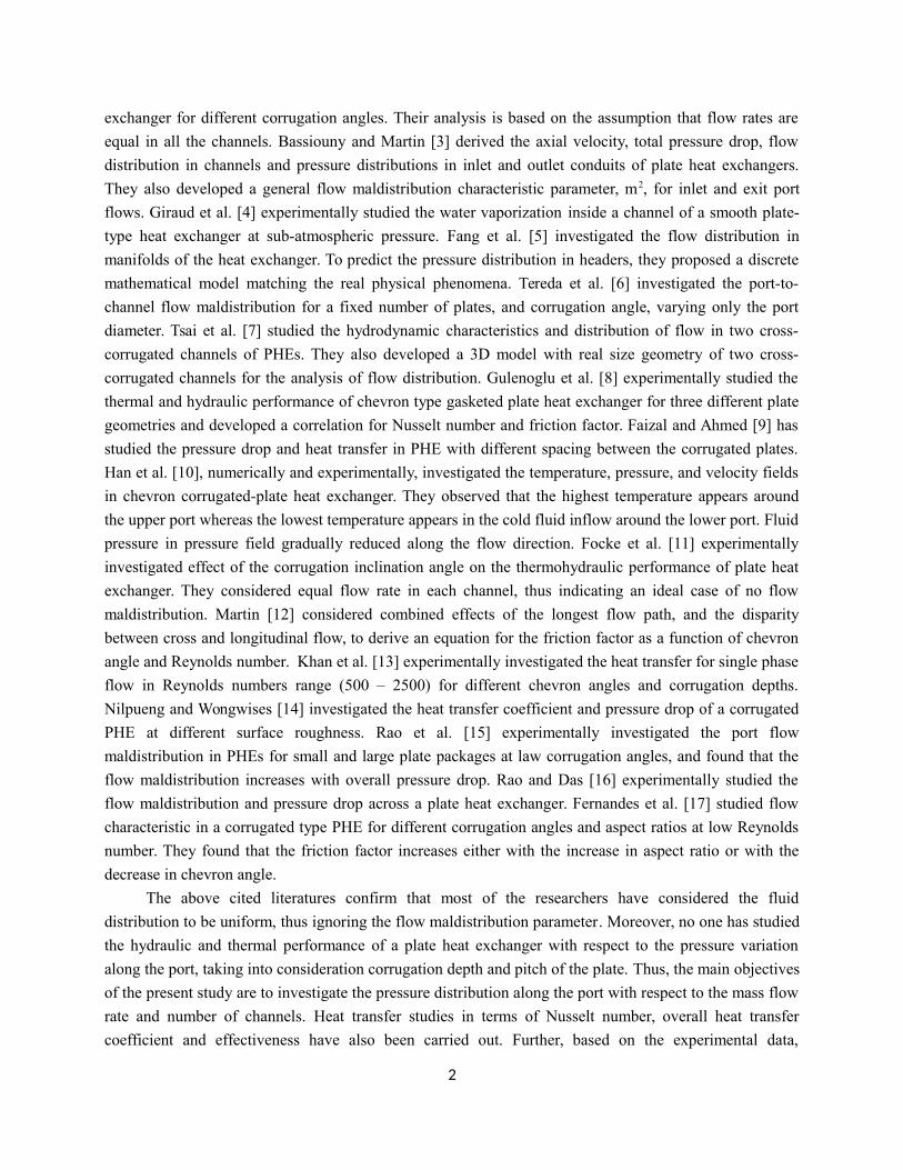
The layout of the experimental set-up as shown in Fig.1 consists of temperature transmitters 1,3,5
and 8, pressure transmitters 2,4,6, and 8, digital flow meters 9 and 10, primary PHE 11, secondary PHE
12, hot water tank 13, cold water tank 14, boiler water tank 15, boiler 16, ground water tank 17, pumps 18,
19, and 20, water treatment plant 21 and 22, pressure gauge 23, condenser 24, valves 25,26 and 27, and
programmable logic control unit (PLC). White arrows in the figure depict the direction of flow of hot fluid
while the dark arrows depict the direction of flow of cold fluid. Fig. 2 presents the flow arrangement of a
U-type PHE. PID (proportional integral derivative) temperature controller regulates the temperature in
Secondary PHE (12) to obtain the desired hot water temperature. Secondary PHE (12) as shown in Fig. 1,
consists of a maximum of 27 plates. Investigation of the flow distribution is carried out for 15 plates (14
channels), 21 plates (20 channels) and 27 plates (26 channels) from the first to last channel. Digital flow
meters (9&10), with a maximum deviation of 2.0% from the standard flow meter, and four PT-100
thermometers (1,3,5 & 8), with a maximum deviation of 1% from the standard thermometer, are provided
in hot and cold fluid streams.
Fig.1 Schematic layout of experimental set-up
The maximum operating steam pressure and temperature of boiler are 7.5 bars and 160oC. Steam
enters in primary PHE at 2 bars and 135oC, heating the water to desired temperature. This heated water is
used in secondary PHE to heat the water coming from the cold-water tank. Steam after leaving the primary
PHE condenses in the condenser. Thermometers are placed near to the ports of PHE in the stainless-steel
pipe section at the inlet and outlet of fluid streams. Four pressure transmitters (2,4,6 & 7), calibrated with
a standard pressure meter and with an uncertainty of ±0.25%, are provided near the inlet and outlet port of
cold and hot fluid streams. Flow rates of the working fluid (demineralized water) being pumped by pumps
(19 & 20), is controlled by speed of the pump. Digital flow meters (turbine type flow meter), pressure
transmitters and thermometers are connected to a Programming Logic Controller (PLC), which is further
3
1,3,5&8= Temperature transmitter,2,4,6&7=Pressuretransmitter,9&10=Digital flow meter,11= Primary PHE,12=Secondary PHE, 13=Hot water tank, 14=Cold water tank,15= Boiler water tank, 16=Boiler, 17=Ground water tank, 18,19&20=Pump, 21&22=Water treatment plant, 23=Pressure gauge, 24=Condenser, 25,26,&27= valve
19
11 12
PLC
13 1416
15
17
2122
20
18
1
4
2
3
56
78
9
10
23
24
25
26 27
connected to a Human Interface unit (HMI). PLC measures and controls the temperatures, pressure and
flow rates of hot and cold fluid streams.
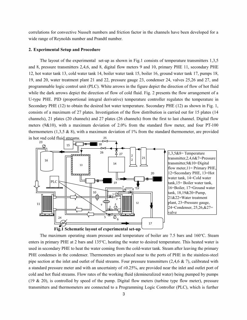
In addition to this, pressure transmitters (range: 0 -500 kPa) having a copper tube are used to
measure the pressure drop along the channels. The typical connection of this tube acting as a pressure tap
with the experimental chevron plate is shown in Fig. 3.
Fig. 2 Flow arrangement for U type PHE Fig. 3 Pressure tap fixed at top and bottom
port of the tasted plate of PHE
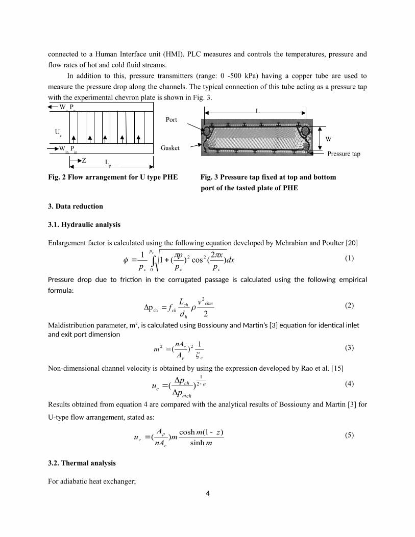
3. Data reduction
3.1. Hydraulic analysis
Enlargement factor is calculated using the following equation developed by Mehrabian and Poulter [20]
dxp
x
p
p
p
cp
ccc 0
22 )2
(cos)(11
(1)
Pressure drop due to friction in the corrugated passage is calculated using the following empiricalformula:
2p
2
ch
chm
h
chch
v
d
Lf (2)
Maldistribution parameter, m2, is calculated using Bossiouny and Martin’s [3] equation for identical inlet and exit port dimension
cp
c
A
nAm
1)( 22 (3)
Non-dimensional channel velocity is obtained by using the expression developed by Rao et al. [15]
a
chm
chc p
pu
2
1
)( (4)
Results obtained from equation 4 are compared with the analytical results of Bossiouny and Martin [3] for
U-type flow arrangement, stated as:
m
zmm
nA
Au
c
pc sinh
)1(cosh)(
(5)
3.2. Thermal analysis
For adiabatic heat exchanger;
4
Z
Win,
Pin
Wo,
Po
Uc
Lp
L
W
Pressure tap
Port
Gasket
cchh TAhTAhQ (6)
Overall heat transfer coefficient is obtained from:
mTUAQ (7)
Experimental results of Nusselt number are compared with the correlational values of Nusselt number
developed by Wang and Sunden [19] for gasketed chevron type plate heat exchanger, stated as:
374.026/13/1 )}2180sin(Re{)(Pr205.0
fNu
w
(8)
Pump power is calculated by,
/.tp pmP (9)
3. The uncertainty in measurements
Uncertainties in measurement of the flow rate, pressure drop, friction factor and Reynolds number, are
calculated from Moffat [18] procedure. Uncertainties in flow rate, pressure, and temperature
measurement are found to be ±2%, ±0.25% and ±0.25% respectively. Maximum uncertainties in the
Reynolds number, friction factor, and Nusselt number are obtained as ±3.9%, ±4.7%, and ±9.5%
respectively.
5. Results and Discussion
5.1 Validation
5.1.1 Comparison of experimental non-dimensional channel velocity with Bossiouncy and Martin [3]
analytical model of three different sets of PHE
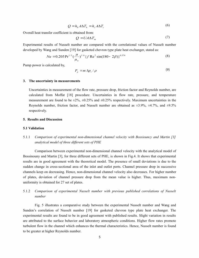
Comparison between experimental non-dimensional channel velocity with the analytical model of
Bossinouny and Martin [3], for three different sets of PHE, is shown in Fig.4. It shows that experimental
results are in good agreement with the theoretical model. The presence of small deviations is due to the
sudden change in cross-sectional area of the inlet and outlet ports. Channel pressure drop in successive
channels keep on decreasing. Hence, non-dimensional channel velocity also decreases. For higher number
of plates, deviation of channel pressure drop from the mean value is higher. Thus, maximum non-
uniformity is obtained for 27 set of plates.
5.1.2 Comparison of experimental Nusselt number with previous published correlations of Nusselt
number
Fig. 5 illustrates a comparative study between the experimental Nusselt number and Wang and
Sunden’s correlation of Nusselt number [19] for gasketed chevron type plate heat exchanger. The
experimental results are found to be in good agreement with published results. Slight variation in results
are attributed to the surface behavior and laboratory atmospheric conditions. Higher flow rates promote
turbulent flow in the channel which enhances the thermal characteristics. Hence, Nusselt number is found
to be greater at higher Reynolds number.
5
Number of channel, n0 2 4 6 8 10 12 14
No
n-di
me
nsio
nal c
hann
el v
elo
city
, u c
0.94
0.96
0.98
1.00
1.02
1.04
1.06
1.08
1.10
Bossiouncy and Martin [3] 27 platesExperimental data for 27 platesBossiouncy and Martin [3] 21 platesExperimental data for 21 platesBossiouncy and Martin [3] 15 platesExperimental data for 15 plates
Fig. 4 Comparison of experimental non-dimensional Fig. 5 Comparison of present correlated
channel velocity with Bossiouncy and Martin [3] Nusselt number with Wang and Sunden
analytical model of three different sets of PHE [19] correlation
5.2. Typical experimental results
5.2.1 Variation of static pressure along the inlet and outlet ports
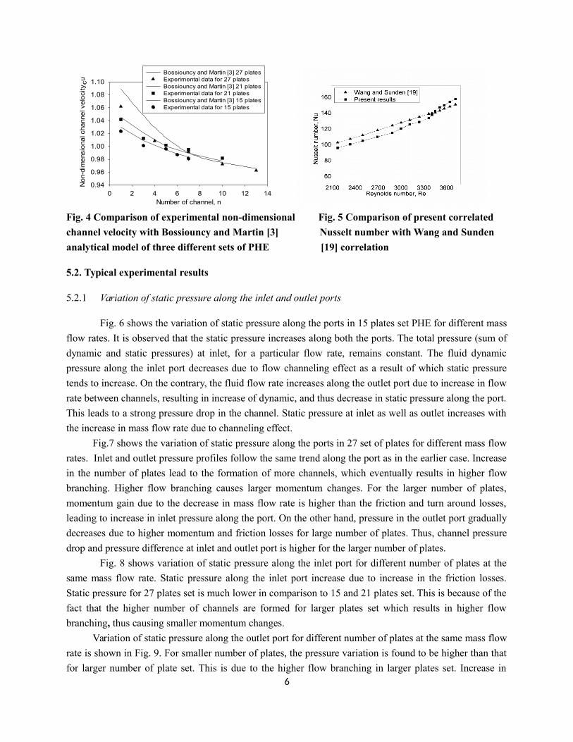
Fig. 6 shows the variation of static pressure along the ports in 15 plates set PHE for different mass
flow rates. It is observed that the static pressure increases along both the ports. The total pressure (sum of
dynamic and static pressures) at inlet, for a particular flow rate, remains constant. The fluid dynamic
pressure along the inlet port decreases due to flow channeling effect as a result of which static pressure
tends to increase. On the contrary, the fluid flow rate increases along the outlet port due to increase in flow
rate between channels, resulting in increase of dynamic, and thus decrease in static pressure along the port.
This leads to a strong pressure drop in the channel. Static pressure at inlet as well as outlet increases with
the increase in mass flow rate due to channeling effect.
Fig.7 shows the variation of static pressure along the ports in 27 set of plates for different mass flow
rates. Inlet and outlet pressure profiles follow the same trend along the port as in the earlier case. Increase
in the number of plates lead to the formation of more channels, which eventually results in higher flow
branching. Higher flow branching causes larger momentum changes. For the larger number of plates,
momentum gain due to the decrease in mass flow rate is higher than the friction and turn around losses,
leading to increase in inlet pressure along the port. On the other hand, pressure in the outlet port gradually
decreases due to higher momentum and friction losses for large number of plates. Thus, channel pressure
drop and pressure difference at inlet and outlet port is higher for the larger number of plates.
Fig. 8 shows variation of static pressure along the inlet port for different number of plates at the
same mass flow rate. Static pressure along the inlet port increase due to increase in the friction losses.
Static pressure for 27 plates set is much lower in comparison to 15 and 21 plates set. This is because of the
fact that the higher number of channels are formed for larger plates set which results in higher flow
branching, thus causing smaller momentum changes.
Variation of static pressure along the outlet port for different number of plates at the same mass flow
rate is shown in Fig. 9. For smaller number of plates, the pressure variation is found to be higher than that
for larger number of plate set. This is due to the higher flow branching in larger plates set. Increase in6
number of plates is also accompanied by higher frictional losses. Thus, flow maldistribution reduces with
decrease in number of plates.
Fig. 6 Variation of static pressure along the Fig. 7 Variation of static pressure along the
port for 15 plates at different mass flow rate port for 27 plates at different mass flow rate
Fig. 8 Variation of static pressure of inlet port Fig. 9 Variation of static pressure of outlet
at constant mass flow rate (1.57 kg/s) port at constant mass flow rate (1.57 kg/s)
5.2.2 Variation of static pressure along the port for isothermal and non-isothermal condition
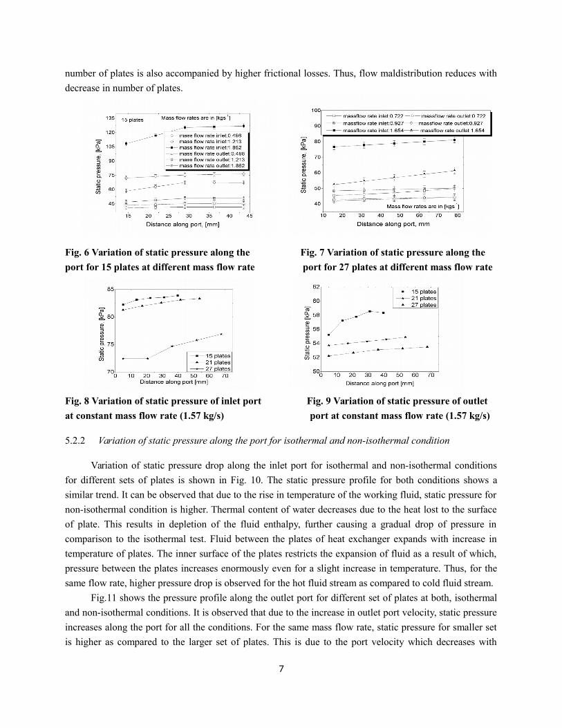
Variation of static pressure drop along the inlet port for isothermal and non-isothermal conditions
for different sets of plates is shown in Fig. 10. The static pressure profile for both conditions shows a
similar trend. It can be observed that due to the rise in temperature of the working fluid, static pressure for
non-isothermal condition is higher. Thermal content of water decreases due to the heat lost to the surface
of plate. This results in depletion of the fluid enthalpy, further causing a gradual drop of pressure in
comparison to the isothermal test. Fluid between the plates of heat exchanger expands with increase in
temperature of plates. The inner surface of the plates restricts the expansion of fluid as a result of which,
pressure between the plates increases enormously even for a slight increase in temperature. Thus, for the
same flow rate, higher pressure drop is observed for the hot fluid stream as compared to cold fluid stream.
Fig.11 shows the pressure profile along the outlet port for different set of plates at both, isothermal
and non-isothermal conditions. It is observed that due to the increase in outlet port velocity, static pressure
increases along the port for all the conditions. For the same mass flow rate, static pressure for smaller set
is higher as compared to the larger set of plates. This is due to the port velocity which decreases with
7
increase in number of plates. Under non-isothermal condition, as the temperature increases, density of
fluid decreases, velocity increases, and hence static pressure increases.
Mass Flow Rate: 1.57 kg/s
Distance along port [mm]0 10 20 30 40 50 60 70 80
Sta
tic P
ressure
[kP
a]
68
70
72
74
76
78
80
82
84
86
15 Plates Isothermal condition15 Plates Non-Isothermal condition21 Plates Isothermal condition21 Plates Non-Isothermal condition27 Plates Isothermal condition27 Plates Non-Isothermal condition
Mass Flow Rate : 1.57 kg/s
Distance along port [mm]0 10 20 30 40 50 60 70 80
Sta
tic P
ressure
[kP
a]
50
52
54
56
58
60
62
15 Plates Isothermal Condition15 Plates Non-Isothermal Condition21 Plates Isothermal Condition21 Plates Non-Isothermal Condition27 Plates Isothermal Condition27 Plates Non-Isothermal Condition
Fig. 10 Variation of static pressure along the inlet Fig. 11Variation of static pressure along the outlet port at isothermal and non-isothermal condition port at isothermal and non-isothermal condition
Fig. 12 Variation of heat transfer rate with Fig. 13 variations of Nusselt number with
pump power Reynolds number
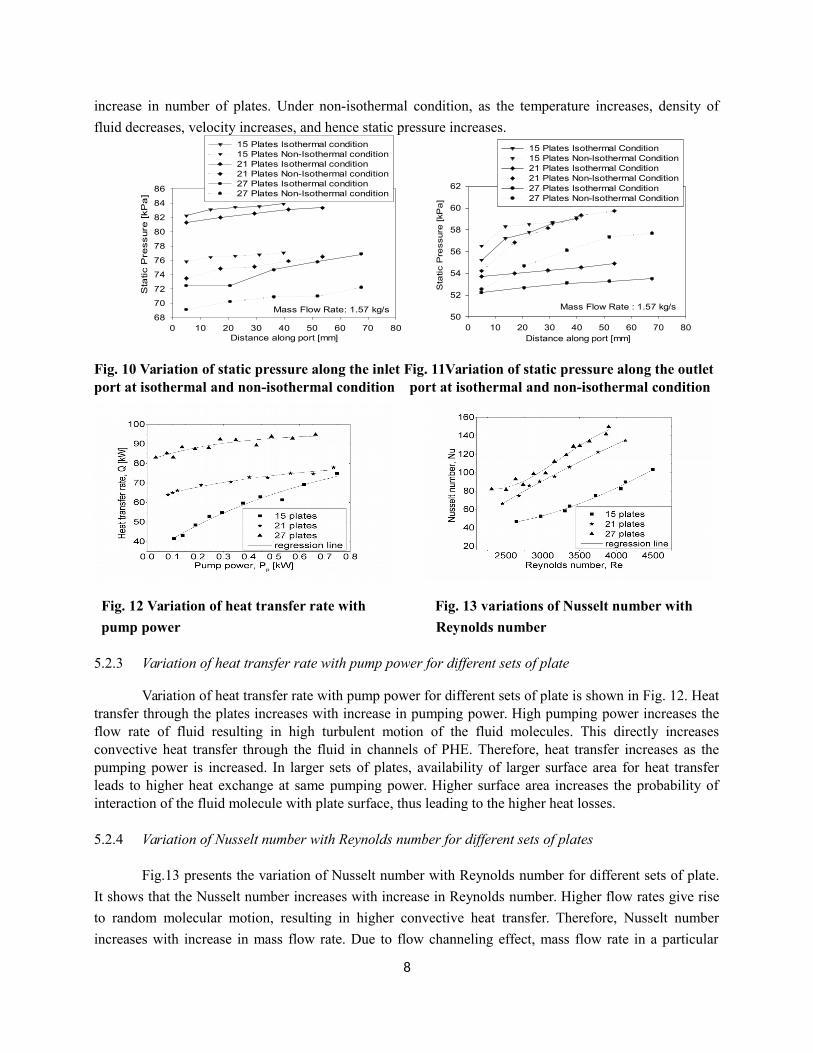
5.2.3 Variation of heat transfer rate with pump power for different sets of plate
Variation of heat transfer rate with pump power for different sets of plate is shown in Fig. 12. Heattransfer through the plates increases with increase in pumping power. High pumping power increases theflow rate of fluid resulting in high turbulent motion of the fluid molecules. This directly increasesconvective heat transfer through the fluid in channels of PHE. Therefore, heat transfer increases as thepumping power is increased. In larger sets of plates, availability of larger surface area for heat transferleads to higher heat exchange at same pumping power. Higher surface area increases the probability ofinteraction of the fluid molecule with plate surface, thus leading to the higher heat losses.
5.2.4 Variation of Nusselt number with Reynolds number for different sets of plates
Fig.13 presents the variation of Nusselt number with Reynolds number for different sets of plate.
It shows that the Nusselt number increases with increase in Reynolds number. Higher flow rates give rise
to random molecular motion, resulting in higher convective heat transfer. Therefore, Nusselt number
increases with increase in mass flow rate. Due to flow channeling effect, mass flow rate in a particular
8
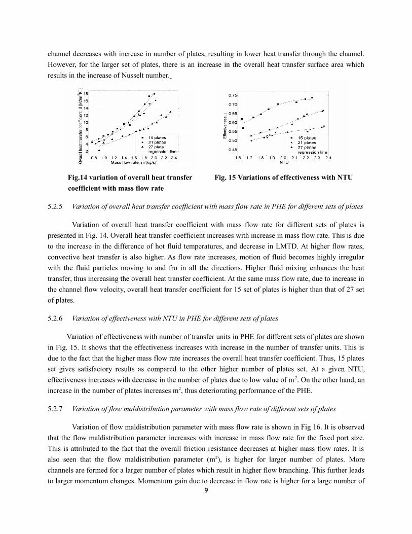
channel decreases with increase in number of plates, resulting in lower heat transfer through the channel.
However, for the larger set of plates, there is an increase in the overall heat transfer surface area which
results in the increase of Nusselt number.
Fig.14 variation of overall heat transfer Fig. 15 Variations of effectiveness with NTU
coefficient with mass flow rate
5.2.5 Variation of overall heat transfer coefficient with mass flow rate in PHE for different sets of plates
Variation of overall heat transfer coefficient with mass flow rate for different sets of plates is
presented in Fig. 14. Overall heat transfer coefficient increases with increase in mass flow rate. This is due
to the increase in the difference of hot fluid temperatures, and decrease in LMTD. At higher flow rates,
convective heat transfer is also higher. As flow rate increases, motion of fluid becomes highly irregular
with the fluid particles moving to and fro in all the directions. Higher fluid mixing enhances the heat
transfer, thus increasing the overall heat transfer coefficient. At the same mass flow rate, due to increase in
the channel flow velocity, overall heat transfer coefficient for 15 set of plates is higher than that of 27 set
of plates.
5.2.6 Variation of effectiveness with NTU in PHE for different sets of plates
Variation of effectiveness with number of transfer units in PHE for different sets of plates are shown
in Fig. 15. It shows that the effectiveness increases with increase in the number of transfer units. This is
due to the fact that the higher mass flow rate increases the overall heat transfer coefficient. Thus, 15 plates
set gives satisfactory results as compared to the other higher number of plates set. At a given NTU,
effectiveness increases with decrease in the number of plates due to low value of m 2. On the other hand, an
increase in the number of plates increases m2, thus deteriorating performance of the PHE.
5.2.7 Variation of flow maldistribution parameter with mass flow rate of different sets of plates
Variation of flow maldistribution parameter with mass flow rate is shown in Fig 16. It is observed
that the flow maldistribution parameter increases with increase in mass flow rate for the fixed port size.
This is attributed to the fact that the overall friction resistance decreases at higher mass flow rates. It is
also seen that the flow maldistribution parameter (m2), is higher for larger number of plates. More
channels are formed for a larger number of plates which result in higher flow branching. This further leads
to larger momentum changes. Momentum gain due to decrease in flow rate is higher for a large number of9
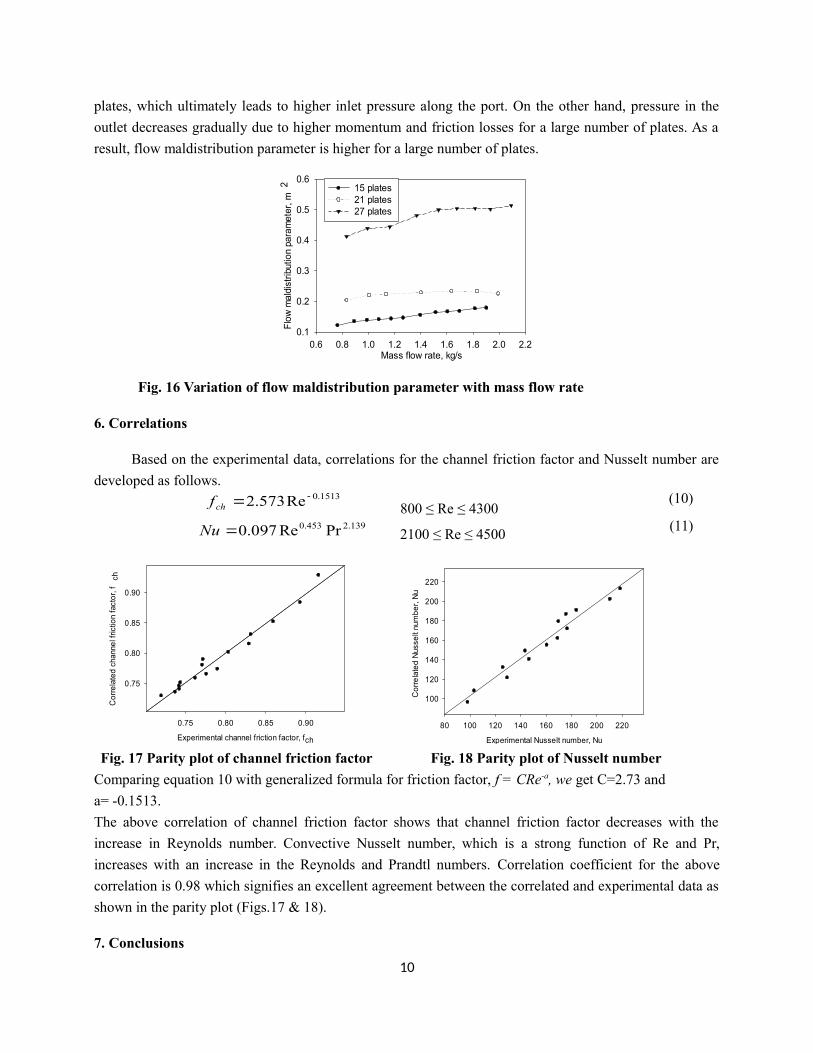
plates, which ultimately leads to higher inlet pressure along the port. On the other hand, pressure in the
outlet decreases gradually due to higher momentum and friction losses for a large number of plates. As a
result, flow maldistribution parameter is higher for a large number of plates.
Mass flow rate, kg/s0.6 0.8 1.0 1.2 1.4 1.6 1.8 2.0 2.2
Flo
w m
aldi
strib
utio
n pa
ram
eter
, m2
0.1
0.2
0.3
0.4
0.5
0.615 plates21 plates 27 plates
Fig. 16 Variation of flow maldistribution parameter with mass flow rate
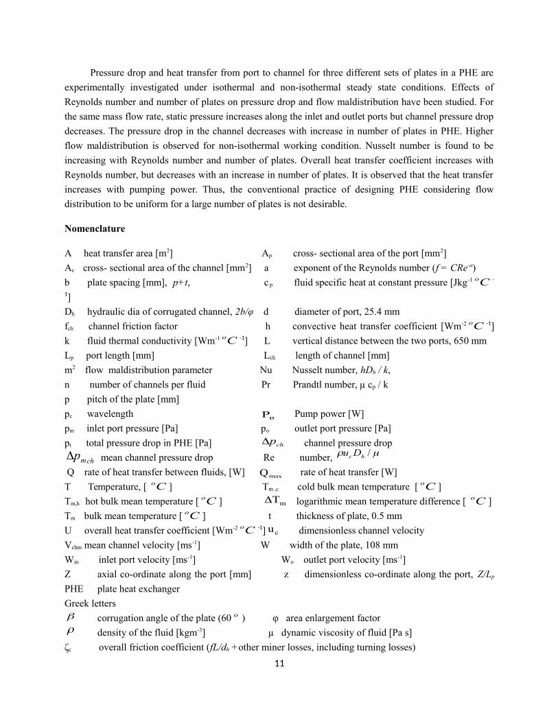
6. Correlations
Based on the experimental data, correlations for the channel friction factor and Nusselt number are
developed as follows.1513.0Re573.2 chf
800 ≤ Re ≤ 4300(10)
139.2453.0 PrRe097.0Nu 2100 ≤ Re ≤ 4500
(11)
Experimental channel friction factor, fch
0.75 0.80 0.85 0.90
Cor
rela
ted
chan
nel f
rictio
n fa
ctor
, fch
0.75
0.80
0.85
0.90
Experimental Nusselt number, Nu
80 100 120 140 160 180 200 220
Cor
rela
ted
Nus
selt
num
ber,
Nu
100
120
140
160
180
200
220
Fig. 17 Parity plot of channel friction factor Fig. 18 Parity plot of Nusselt number
Comparing equation 10 with generalized formula for friction factor, f = CRe-a, we get C=2.73 and
a= -0.1513.
The above correlation of channel friction factor shows that channel friction factor decreases with the
increase in Reynolds number. Convective Nusselt number, which is a strong function of Re and Pr,
increases with an increase in the Reynolds and Prandtl numbers. Correlation coefficient for the above
correlation is 0.98 which signifies an excellent agreement between the correlated and experimental data as
shown in the parity plot (Figs.17 & 18).
7. Conclusions
10
Pressure drop and heat transfer from port to channel for three different sets of plates in a PHE are
experimentally investigated under isothermal and non-isothermal steady state conditions. Effects of
Reynolds number and number of plates on pressure drop and flow maldistribution have been studied. For
the same mass flow rate, static pressure increases along the inlet and outlet ports but channel pressure drop
decreases. The pressure drop in the channel decreases with increase in number of plates in PHE. Higher
flow maldistribution is observed for non-isothermal working condition. Nusselt number is found to be
increasing with Reynolds number and number of plates. Overall heat transfer coefficient increases with
Reynolds number, but decreases with an increase in number of plates. It is observed that the heat transfer
increases with pumping power. Thus, the conventional practice of designing PHE considering flow
distribution to be uniform for a large number of plates is not desirable.
Nomenclature
A heat transfer area [m2] Ap cross- sectional area of the port [mm2]
Ac cross- sectional area of the channel [mm2] a exponent of the Reynolds number (f = CRe-a)
b plate spacing [mm], p+t, c p fluid specific heat at constant pressure [Jkg-1 Co -
1]
Dh hydraulic dia of corrugated channel, 2b/φ d diameter of port, 25.4 mm
fch channel friction factor h convective heat transfer coefficient [Wm-2 Co -1]
k fluid thermal conductivity [Wm-1 Co -1] L vertical distance between the two ports, 650 mm
Lp port length [mm] Lch length of channel [mm]
m2 flow maldistribution parameter Nu Nusselt number, hDh / k,
n number of channels per fluid Pr Prandtl number, µ cp / k
p pitch of the plate [mm]
pc wavelength pP
Pump power [W]
pin inlet port pressure [Pa] po outlet port pressure [Pa]
pt total pressure drop in PHE [Pa] chp channel pressure drop
chmp mean channel pressure drop Re number, /hc Du
Q rate of heat transfer between fluids, [W] maxQ rate of heat transfer [W]
T Temperature, [ Co ] Tm ,c cold bulk mean temperature [ Co ]
Tm,h hot bulk mean temperature [ Co ] mT logarithmic mean temperature difference [ Co ]
Tm bulk mean temperature [ Co ] t thickness of plate, 0.5 mm
U overall heat transfer coefficient [Wm-2 Co -1] cu dimensionless channel velocity
Vchm mean channel velocity [ms-1] W width of the plate, 108 mm
Win inlet port velocity [ms-1] Wo outlet port velocity [ms-1]
Z axial co-ordinate along the port [mm] z dimensionless co-ordinate along the port, Z/Lp
PHE plate heat exchanger
Greek letters corrugation angle of the plate (60 o ) φ area enlargement factor density of the fluid [kgm-3] µ dynamic viscosity of fluid [Pa s]
ζc overall friction coefficient (fL/dh +other miner losses, including turning losses)
11
effectiveness
References
[1] Mueller, A.C., Chiou, J.P., Review of Various Types of Flow Maldistribution in Heat Exchangers,
Heat Transfer Engineering, 9 (1988), 2, pp. 36-50
[2] Muley, A., Manglik, R.M., Experimental Study of Turbulent Flow Heat Transfer and Pressure Drop in
Plate Heat Exchanger with Chevron Plates, ASME Journal of Heat Transfer, 121 (1999), 1, pp. 110–
117
[3] Bassiouny, M.K., Martin, H., Flow distribution and pressure drop in plate heat exchangers-I , Chem.
Eng. Sci., 39 (1984), pp. 693-700
[4] Giraud, F., Toublanc, C., Rullière, R., Bonjour, J., Clausse, M., Experimental study of water
vaporization occurring inside a channel of a smooth plate-type heat exchanger at subatmospheric
pressure, Applied Thermal Engineering 106 (2016), pp. 180–191–
[5] Lu F., Luo Y.H., Yang S.M., Analytical and Experimental Investigation of Flow Distribution in
Manifolds for Heat Exchangers, Journal of Hydrodynamics, 20 (2008), 2, pp.179-185
[6] Tereda, F.A., Srihari, N., Sunden, B., Das, S.K., Experimental Investigation on Port-to-Channel Flow
Maldistribution in Plate Heat Exchangers, ASME Journal of Heat Transfer Engineering, 28 (2005), 5,
pp. 435-443
[7] Tsai, Y.C., Liu, F.B., Shen, P.T., Investigation of pressure drop and flow distribution in a chevron-type
plate heat exchanger, International Communications in Heat and Mass transfer, 36, (2009), pp. 574-
578
[8] Gulenoglu, C., Akturk, F., Aradag, S., Uzol, N.S., Kakac, S., Experimental Comparison of performance
of three different plates for gasketed plate heat exchangers, International Journal of Thermal Science,
75 (2014), pp. 249-256
[9] Faizal, M., Ahmed, M.R., Experimental Studies on a Corrugated Plate Heat Exchanger for Small
Temperature Difference Applications, Experimental Thermal and Fluid Science, 36 (2012), pp. 242-
248
[10] Han, X.H., Cui, L.Q., Chen, S.J., Chen, G.M., Wang, Q., A numerical and experimental study of
chevron, corrugated-plate heat exchangers, International Communications in Heat and Mass Transfer,
37 (2010), pp. 1008-1014
[11] Focke, W.W., Zachariades, J., Olivier, I., The effect of the corrugation inclination angle on the
thermohydraulic performance of plate heat exchangers, International Journal of Heat and Mass
Transfer, 28 (1985), 8, pp. 1469-1479
[12] Martin, H., A theoretical approach to predict the performance of chevron-type plate heat exchangers,
Chemical Engineering and Processing, 35 (1996), pp. 301-310
[13] Khan, T.S., Khan, M.S., Chyu, M.C., Ayub, Z.H., Experimental investigation of single phase
convective heat transfer coefficient in a corrugated plate heat exchanger for multiple plate
configurations, Applied Thermal Engineering, 30 (2010), pp. 1058–1065
12
[14] Nilpueng, K., Wongwises, S., Experimental study of single-phase heat transfer and pressure drop
inside a plate heat exchanger with a rough surface, Experimental Thermal and Fluid Science, 68,
(2015), pp. 268–275
[15] Bobbili, P.R., Sunden, B., Das, S.K., An experimental investigation of the port flow maldistribution in
small and large plate package heat exchangers, Applied Thermal Engineering, 26 (2006), pp.1919-1926
[16] Bobbili. P.R., Das, S.K., An experimental study on the influence of flow maldistribution on the
pressure drop across a plate heat exchanger, ASME Journal of Fluid Engineering, 126 (2006), pp. 680-
691
[17] Fernandes, C.S., Dias, R.P., Nóbrega, J.M., Maia, J.M., Laminar flow in chevron-type plate heat
exchangers: CFD analysis of tortuosity, shape factor and friction factor, Chemical Engineering and
Processing, 46 (2007), pp. 825–833
[18] Moffat, R.J., Describing the uncertainties in experimental results, Experimental Thermal and Fluid
Science, 3 (1988), pp. 3-11
[19] Wang, L., Sunden, B., Optimal design of plate heat exchangers with and without pressure drop
specifications, Applied Thermal Engineering, 23 (2003), pp. 295–311
[20] Mehrabian, M.A., Poulter, R., Hydrodynamics and thermal characteristics of corrugated channels:
computational approach, Applied Mathematical Modelling, 24 (2000), pp. 343-364
13