Embed Size (px)
Citation preview

ARTICLESPUBLISHED ONLINE: 9 FEBRUARY 2015 | DOI: 10.1038/NMAT4206
Hydraulic fracture during epithelial stretchingLaura Casares1, Romaric Vincent1, Dobryna Zalvidea1, Noelia Campillo1,2, Daniel Navajas1,2,Marino Arroyo3* and Xavier Trepat1,2,4*
The origin of fracture in epithelial cell sheets subject to stretch is commonly attributed to excess tension in the cells’cytoskeleton, in the plasma membrane, or in cell–cell contacts. Here, we demonstrate that for a variety of synthetic andphysiological hydrogel substrates the formation of epithelial cracks is caused by tissue stretching independently of epithelialtension. We show that the origin of the cracks is hydraulic; they result from a transient pressure build-up in the substrateduring stretch and compression manoeuvres. After pressure equilibration, cracks heal readily through actomyosin-dependentmechanisms. The observed phenomenology is captured by the theory of poroelasticity, which predicts the size and healingdynamics of epithelial cracks as a function of the sti�ness, geometry and composition of the hydrogel substrate. Our findingsdemonstrate that epithelial integrity is determined in a tension-independent manner by the coupling between tissue stretchingand matrix hydraulics.
Epithelial cell sheets are two-dimensional active materialscapable of performing a wide diversity of functions, includingmorphogenesis, wound healing, tissue compartmentalization,
and protection against environmental pathogens1. Epithelial sheetscarry out these functions in a dynamic mechanical environmentcharacterized by elevated levels of cell and tissue stretching2,3. Dur-ing epithelial morphogenesis, for example, cells experience severalfold changes in their surface area to enable the formation of complexthree-dimensional shapes4,5. During adult life, the epithelium of di-verse organs functions routinely in the presence of significant levelsof stretch, such as those arising from breathingmanoeuvres, cardiacpulses, or peristaltic contractions2. Under physiological conditions,stretch is a potent stimulus for growth, differentiation, secretion, re-modelling and gene expression6–9. Failure to withstand stretch, how-ever, causes epithelial fracture, which may lead to developmentaldefects and severe clinical conditions10–12.
Mechanisms underlying epithelial fracture during stretch arepoorly understood, but they are commonly associatedwith excessivetension in key stress-bearing elements of the cell monolayer. Indeed,excessive tension due to monolayer overstretching or cytoskeletalcontraction has been shown to cause the disruption of cell–celland cell–matrix adhesions12–15. Excessive tension has also beenshown to rupture the cell membrane16,17, which may lead tocell death and formation of cracks within the epithelium18. Herewe developed a new experimental approach to study fracturedynamics of micropatterned epithelial monolayers adhered to softhydrogel substrates. Using this approach we demonstrate that tissuestretching causes epithelial cracks whose origin is not tensile, butrather hydraulic.
A device to study epithelial mechanics during stretchThe principle of the technique is as follows. A thin layer of softhydrogel is polymerized and chemically attached on a stretchablepolydimethylsiloxane (PDMS) membrane (Fig. 1a,b). The resultingdouble-layered substrate is mounted on a custom-made stretchingdevice compatible with inverted and upright optical microscopy(Fig. 1a). The substrate is stretched over a lubricated O-ringby applying negative pressure underneath its outer annular area
(Supplementary Fig. 1a). The device produces homogeneous andequibiaxial strain with a user-controlled amplitude and time course(Supplementary Fig. 1b,c).
As an experimental model system we used Madin-Darby caninekidney (MDCK) epithelial cells adhered on soft polyacrylamide(PAA) hydrogel substrates. To enhance experimental reproducibilityand to improve mechanical characterization of the system, weused micropatterning technology to restrict the cells to circularislands pre-coated with collagen-I14,19 (Supplementary Methods).When cells were seeded on these islands they readily formedcohesive clusters comprising ∼15–20 cells. In the absence ofstretch, the clusters exhibited characteristic features of epitheliallayers, including tight junctions, adherens junctions, and F-actinaccumulation at the lateral cell membranes (Supplementary Fig. 2).
Epithelial clusters fracture on stretch releaseWe first subjected the hydrogels and the overlying cells to a 10-minpulse of stretch and 10% biaxial strain (Fig. 1c). On stretching,no changes were apparent in cell morphology, actin distributionand cluster cohesiveness. Promptly after stretch cessation, however,cracks of diverse size and shape appeared between the cortices ofadjacent cells, healing within minutes (Fig. 1c and SupplementaryMovies 1 and 2). These interfacial cracks did not originate froma transient detachment of the cortex from the membrane, as iscommonly seen in blebbing-like phenomena20,21 or during thedissociation of cell doublets under tension22. Instead, the cell cortex,the cell membrane and E-cadherin remained localized at the crackperiphery, indicating the dissociation of adherens junctions at thecadherin–cadherin level (Fig. 1d,e and Supplementary Fig. 3 andSupplementary Movie 3).
Importantly, the observed responses were not specific to cellsseeded on synthetic PAA hydrogels; epithelial clusters seededon Matrigel—a physiological mixture of growth factors andstructural proteins such as laminin, entactin and collagen—showed similar cracks and healing dynamics (SupplementaryFig. 4). To further assess whether epithelial fracture occurred inphysiological matrices, we decellularized porcine trachea and usedit as substrate. Similarly to the case of PAA and Matrigel, cell
1Institute for Bioengineering of Catalonia, 08028 Barcelona, Spain. 2Unitat de Biofísica i Bioenginyeria, Facultat de Medicina, Universitat de Barcelona, andCIBERES, 08036 Barcelona, Spain. 3Universitat Politècnica de Catalunya-BarcelonaTech, 08034 Barcelona, Spain. 4Institució Catalana de Recerca i EstudisAvançats (ICREA), 08010 Barcelona, Spain. *e-mail: [email protected]; [email protected]
NATUREMATERIALS | VOL 14 | MARCH 2015 | www.nature.com/naturematerials 343
© 2015 Macmillan Publishers Limited. All rights reserved

ARTICLES NATURE MATERIALS DOI: 10.1038/NMAT4206
LifeAct Plasmamembrane
StretchBaseline
10% strainUnstretch
t
t = −1 min t = 1 min t = 9 min t = 11 min t = 21 min
Vacuum Vacuum
O
bjec
tive
Obj
ectiv
ea c
b
d
fh
ig
e
LifeAct E-cadh
Hydrogel
PDMS
Cells
Crac
k ar
ea (%
)
Strain
5%10%15%
02468
10
Crac
k ar
ea (%
)
High cell density
Low cell density
Phal
loid
in/Z
O-1
Ph
allo
idin
/ZO
-1
02468
10
Figure 1 | Epithelial fracture during stretch–unstretch manoeuvres. a, Scheme of the stretching device (see Methods and Supplementary Fig. 1).b, Zoomed view of the region enclosed by a dashed rectangle in a. c, LifeAct-GFP MDCK cluster before, during and after a 10 min pulse of 10% biaxialstrain. The bottom row is a zoom of the region highlighted in the top row. Arrowheads indicate cracks after stretch cessation. The acquisition time of eachsnapshot is marked by a black dot on the time axis (top). d, Live fluorescence images of MDCK cells expressing LifeAct-Ruby and a fluorescently labelledplasma membrane green marker. Images were obtained 30 s after stretch cessation. Scale bar, 5 µm. e, Live fluorescence images of MDCK cells expressingLifeAct-GFP and E-cad-RFP. Images were obtained 30 s after stretch cessation. Scale bar, 5 µm. f,g, Confocal x–y, x–z and y–z sections of cracks at di�erentz-planes. Cells were fixed immediately after stretch cessation and stained for F-actin (phalloidin, red) and ZO-1 (green; Supplementary Methods). Sectionsshow that ZO-1 remained intact at the apical surface (white arrows). In f, a discontinuous actin layer was present at the basal surface of the cluster (bluearrowheads) and the largest crack diameter was located in the medial plane. In g, no basal actin layer was present and the largest crack diameter waslocated in the basal plane. See Supplementary Fig. 6 for confocal sections of additional cracks (scale bar, 5 µm). h, Crack area in epithelial clusters at highdensity (37±3 cells per pattern, mean± s.e.m., n=5) and low density (19± 1 cells per pattern, mean± s.e.m., n=5). Representative images of theclusters before and after stretch are shown in Supplementary Fig. 9. i, Dependence of crack area on strain (n=6). In h and i, crack area was expressed as apercentage of the total pattern area. Epithelial clusters are 80 µm in diameter.
clusters seeded on these substrates showed interfacial cracks onunstretching (Supplementary Fig. 5). In light of the generality of thephenomenology, we focus our attention hereafter on PAAhydrogels,which show higher reproducibility, accessibility, and versatility thanMatrigel or decellularized animal tissue.
Morphological and structural characterization of the cracksTo characterize the morphology of the cracks we analysed thelocalization of F-actin and the tight junction protein ZO-1 atdifferent z-planes immediately after stretch cessation (Fig. 1f,g).This analysis showed that despite the rupture of adherens junctions(Fig. 1e and Supplementary Fig. 3) most tight junctions remainedintact (Fig. 1f,g and Supplementary Fig. 6). However, on rareoccasions tight junctions also failed, thus fully compromisingepithelial permeability (Supplementary Fig. 7). In some cracks,the largest diameter was located in medial cell planes and adiscontinuous actin layer was present at their basal side (Fig. 1f).In other cracks, this discontinuous actin layer was absent and thelargest crack diameter was located at the cell base (Fig. 1g andSupplementary Fig. 6).
We next studied whether epithelial fracture involved not onlyfailure of cell–cell adhesions but also failure of cell–substrate
adhesions. To do so, we subjected cells labelled with LifeAct-Rubyand Talin-GFP to a 10-min pulse of 10% stretch (SupplementaryFig. 8). Before stretch, talin accumulated at discrete focal adhesionsthroughout the monolayer. This spatial distribution did not varyduring the application of the stretch pulse. On stretch cessation,however, talin localized at the crack contour and some focaladhesions under the cracks experienced shape changes. Thesedata indicate that crack formation involves the disruption andremodelling of focal adhesions within epithelial clusters.
The polarity, mechanics and cytoskeletal organization ofepithelial layers depends on cell density23. To study the role ofcell density in epithelial fracture we subjected micropatternedislands grown at different densities to a 10-min pulse of 10% strain.Cells at higher densities exhibited significantly lower crack areas,indicating that maturity of cell–cell junctions and the corticalorganization of the actin cytoskeleton play a significant role indetermining the formation and growth of epithelial cracks (Fig. 1hand Supplementary Fig. 9).
To study the dependence of crack formation on stretchmagnitude, we subjected the clusters to a series of stretch pulsesof the same duration (10 min) but different magnitude (5%, 10%or 15% strain). These pulses were applied in random order and
344 NATUREMATERIALS | VOL 14 | MARCH 2015 | www.nature.com/naturematerials
© 2015 Macmillan Publishers Limited. All rights reserved

NATURE MATERIALS DOI: 10.1038/NMAT4206 ARTICLES
0.51.01.5
2.02.5
Tens
ion
0% strain (control)10% strain
1 s 1 min 10 minPerc
enta
ge o
f ju
nctio
ns
with
cra
cks
10% strain
10%
10%
10%
t
t
Trac
tion
(Pa)
Te
nsio
n (m
N m
−1)
Trac
tion
(Pa)
Te
nsio
n (m
N m
−1)
0 5
Trac
tion
t (min) 0 5
t (min)
1 s stretch1 min stretch10 min stretch
Tens
ion
1 s stretch1 min stretch10 min stretch
Traction
Tension
t
0 5 10 15
Trac
tion
t (min)
0 5 10 15t (min)
0% strain (control)10% strain
10% strain
10% 10%
StretchBaseline
a
c
d e
f
b
g
h
i j
Unstretch
t = −1 min t = 0.5 min t = 10 min t = 11 min t = 18 min
t = −1 min t = 0.5 min t = 18 min
t = −1 min t = 11 min t = 40 min t = 41 min t = 49 min
020406080
100
0.5
1.0
1.5
2.0
0.5
0.7
0.9
1.1
0.5
0.7
0.9
1.1
25020015010050
7.5
2.50
5.0
25020015010050
7.5
2.50
5.0
Figure 2 | Cracks are independent of epithelial tension. a, Time-lapse imaging of patterned clusters (top) and zoomed regions (bottom) of MDCK cellsexpressing LifeAct-GFP before and after application of successive pulses of 10 min and 1 s. Arrowheads point at cracks. The acquisition time of eachsnapshot is marked by a black dot on the time axis. b, Percentage of junctions with cracks after stretch pulses of 1 s, 1 min or 10 min. Stretch pulses wereapplied consecutively to each pattern in a random order, spaced by>15 min (n=6 di�erent patterns). c,d, Colour maps showing traction forces (top) andepithelial tension (bottom) before, during and after a 10 min (c) or 1 s (d) stretch pulses. Phase contrast images on the left show the measured MDCK cellcluster. e,f, Schemes illustrating the physical meaning of traction and tension in the epithelial clusters. g,h, Traction forces and tension, respectively, duringand after a 10% strain pulse of 10 min versus a 0% strain (both normalized to baseline levels). i,j, Traction forces and tension, respectively, after stretchpulses of di�erent duration (both normalized to baseline levels). Error bars in g–j show the s.e.m. of n=6 clusters per condition. Epithelial clusters are80 µm in diameter.
spaced at 30min intervals to enable healing. These experimentsrevealed that total crack area increased with strain magnitude andthat any potential threshold for crack formation must fall below 5%strain (Fig. 1i).
To further characterize the cracks, we subjected the clusters to aseries of three stretch pulses of the same magnitude (10% strain)but different duration (1 s, 1min or 10min), applied in randomorder and spaced at 30min intervals (Fig. 2a). These experimentsshowed that the number and size of the cracks increased with theduration of stretch; in response to 10min pulses, most cell–celljunctions exhibited cracks, whereas in response to 1 s pulses crackswere largely absent (Fig. 2b).
Epithelial cracks are independent of epithelial tensionThe fracture of epithelial monolayers subjected to stretch iscommonly attributed to the mechanical failure of cell–cell junctionsdue to large tensile stresses12–15. However, tension levels withincell monolayers have never been measured during stretching. Todo so, we mapped traction forces at the cell/substrate interfaceusing monolayer traction force microscopy24, as well as themonolayer tension within and between cells using monolayer stressmicroscopy25 (Fig. 2c–f).
Before stretch application, traction forces localized predomi-nantly but not exclusively at the margin of the clusters (Fig. 2c andSupplementary Fig. 10). However, these marginal tractions were notbalanced locally at the subcellular level. Instead, they were transmit-ted through cell–cell junctions, giving rise to an average monolayertension of 4.2mNm−1. On application of a 10-min stretch pulse, celltractions at the cluster periphery andmonolayer tension throughoutthe cluster experienced a rapid increase, followed by a slow relax-ation towards values that were slightly higher than baseline levels(Fig. 2c,g,h and Supplementary Fig. 10). Immediately after stretchcessation, tractions and tensions dropped below baseline levels andrecovered within minutes (Fig. 2c,g,h).
This type of mechanical response to stretch has been previouslyfound in single isolated cells26–28. The increase in tension onstretching, which is generically termed reinforcement, is commonlyattributed to rapid mechanotransduction responses as well asto passive strain hardening of the actomyosin cytoskeleton29–31.Conversely, the drop of tension after stretch cessation, which iscommonly termed fluidization, is attributed to unspecific inelasticrearrangements in the cytoskeleton26,28,32. Our findings show thatthe paradigms of reinforcement and fluidization scale up to thesupracellular level. More intriguingly, they show that, contrary to
NATUREMATERIALS | VOL 14 | MARCH 2015 | www.nature.com/naturematerials 345
© 2015 Macmillan Publishers Limited. All rights reserved
ARTICLES NATURE MATERIALS DOI: 10.1038/NMAT4206
PDMS
PAA
Cell cluster
3
0
−2
Solvent pressure (kPa)
t = 0 st = 1,200 s
t = 0+ s t = 1 s t = 60 s t = 600 s
t = 600+ st = 601 st = 660 s
Stretch
Z
Z
R
Unstretch
Swelling
De-swelling
Swelling
De-swellinga
c e
f
gd
b
V0 < V3
V2 > V0
V3 = V2
V1 = V0
PAA PDMS
Stretch Unstretch
Stretch Unstretch
0.85
0.90
0.95
1.00
1.05
1.10
Nor
mal
ized
gel
thic
knes
s
t (min)
10 min stretch1 min stretch1 s stretch
0 5 10 15 20
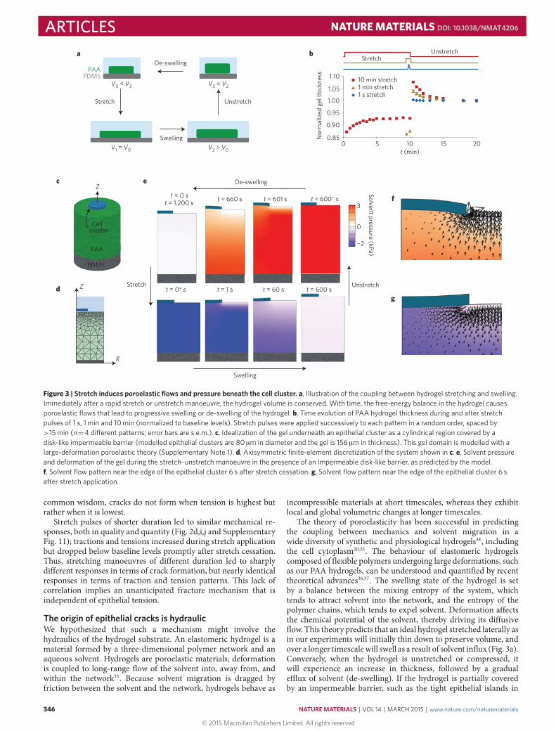
Figure 3 | Stretch induces poroelastic flows and pressure beneath the cell cluster. a, Illustration of the coupling between hydrogel stretching and swelling.Immediately after a rapid stretch or unstretch manoeuvre, the hydrogel volume is conserved. With time, the free-energy balance in the hydrogel causesporoelastic flows that lead to progressive swelling or de-swelling of the hydrogel. b, Time evolution of PAA hydrogel thickness during and after stretchpulses of 1 s, 1 min and 10 min (normalized to baseline levels). Stretch pulses were applied successively to each pattern in a random order, spaced by>15 min (n=4 di�erent patterns; error bars are s.e.m.). c, Idealization of the gel underneath an epithelial cluster as a cylindrical region covered by adisk-like impermeable barrier (modelled epithelial clusters are 80 µm in diameter and the gel is 156 µm in thickness). This gel domain is modelled with alarge-deformation poroelastic theory (Supplementary Note 1). d, Axisymmetric finite-element discretization of the system shown in c. e, Solvent pressureand deformation of the gel during the stretch–unstretch manoeuvre in the presence of an impermeable disk-like barrier, as predicted by the model.f, Solvent flow pattern near the edge of the epithelial cluster 6 s after stretch cessation. g, Solvent flow pattern near the edge of the epithelial cluster 6 safter stretch application.
common wisdom, cracks do not form when tension is highest butrather when it is lowest.
Stretch pulses of shorter duration led to similar mechanical re-sponses, both in quality and quantity (Fig. 2d,i,j and SupplementaryFig. 11); tractions and tensions increased during stretch applicationbut dropped below baseline levels promptly after stretch cessation.Thus, stretching manoeuvres of different duration led to sharplydifferent responses in terms of crack formation, but nearly identicalresponses in terms of traction and tension patterns. This lack ofcorrelation implies an unanticipated fracture mechanism that isindependent of epithelial tension.
The origin of epithelial cracks is hydraulicWe hypothesized that such a mechanism might involve thehydraulics of the hydrogel substrate. An elastomeric hydrogel is amaterial formed by a three-dimensional polymer network and anaqueous solvent. Hydrogels are poroelastic materials; deformationis coupled to long-range flow of the solvent into, away from, andwithin the network33. Because solvent migration is dragged byfriction between the solvent and the network, hydrogels behave as
incompressible materials at short timescales, whereas they exhibitlocal and global volumetric changes at longer timescales.
The theory of poroelasticity has been successful in predictingthe coupling between mechanics and solvent migration in awide diversity of synthetic and physiological hydrogels34, includingthe cell cytoplasm20,35. The behaviour of elastomeric hydrogelscomposed of flexible polymers undergoing large deformations, suchas our PAA hydrogels, can be understood and quantified by recenttheoretical advances36,37. The swelling state of the hydrogel is setby a balance between the mixing entropy of the system, whichtends to attract solvent into the network, and the entropy of thepolymer chains, which tends to expel solvent. Deformation affectsthe chemical potential of the solvent, thereby driving its diffusiveflow. This theory predicts that an ideal hydrogel stretched laterally asin our experiments will initially thin down to preserve volume, andover a longer timescalewill swell as a result of solvent influx (Fig. 3a).Conversely, when the hydrogel is unstretched or compressed, itwill experience an increase in thickness, followed by a gradualefflux of solvent (de-swelling). If the hydrogel is partially coveredby an impermeable barrier, such as the tight epithelial islands in
346 NATUREMATERIALS | VOL 14 | MARCH 2015 | www.nature.com/naturematerials
© 2015 Macmillan Publishers Limited. All rights reserved

NATURE MATERIALS DOI: 10.1038/NMAT4206 ARTICLES10%
Thin
Thic
kCo
ntro
l
Nor
mal
ized
gel
thic
knes
s
t (min)
Control modelThin modelThick model
ControlThinThick
Crack size (µm2)
<3>20
3–77–2
0
Crac
k ar
ea (%
)
10%
Soft
Stiff
0246
0246
0246
Cont
rol
Crac
k ar
ea (%
)
SoftControlStiff
2 5Perc
enta
ge o
f ini
tial c
rack
are
a
Unstretch t (min)
ThinControlThick
Stretch Unstretch
Soft
Stiff
Control
t = 11 min t = 12 min t = 15 mint
t = −2 min
a
d
e f
b c
t = 11 min t = 12 min t = 15 mint = −2 min
0 5 10 15 200.8
0.9
1.0
1.1
1.2
0
10
20
30
0
5
10
15
t
Hydraulic pressure (kPa)0.08 3 44
Figure 4 | The origin of cracks is hydraulic. a, Left: Clusters of MDCK cells expressing LifeAct-GFP on PAA hydrogels of di�erent thickness. Right:Time-lapse evolution of the regions highlighted in orange on the left panels before and after a 10 min pulse of 10% biaxial stretch. The acquisition time ofeach snapshot is marked by a black dot on the time axis (top). Arrowheads point to a subset of cracks. b, Time evolution of the thickness of three PAAhydrogels of same sti�ness (12 kPa) but di�erent initial thickness (CT= 168 µm, thin= 54 µm, thick= 358 µm) during and after application of a 10-minstretch pulse. Solid lines are fits of the poroelastic model described in Supplementary Note 1. c, Percentage of the initial crack area that remains open 2 and5 min after unstretching hydrogels of di�erent thickness (n=4 per condition, CT= 156.3±9.8 µm, thin=59.3±3.8 µm, thick=345.0± 15.3 µm,mean± s.e.m.). d, Left: Clusters of MDCK expressing LifeAct-GFP on PAA hydrogels of same initial thickness but di�erent sti�ness (0.2, 12, 200 kPa).Right: Time-lapse evolution of the regions highlighted on the left panels before and after a 10-min 10% biaxial stretch. e, Distribution of crack size 45 s afterunstretch in clusters attached to hydrogels of di�erent sti�ness (0.2 kPa, 12 kPa and 200 kPa). f, Percentage of crack area 45 s after stretch cessation inclusters attached to substrates of di�erent sti�ness. Values on the x-axis are hydraulic pressures at the cell/gel interface estimated from the poroelastictheory (Supplementary Note 1). Error bars show s.e.m. Epithelial clusters are 80 µm in diameter.
our experiments, solvent efflux will be blocked, leading to a localpressure increase across the barrier.
On the basis of this theoretical framework, we hypothesizedthat if the timescale of stretching pulses is comparable to thecharacteristic time of solvent exchange, significant pressuresmight build up across the epithelium on unstretching, potentiallychallenging its mechanical integrity. If this hypothesis were true, cellclusters adhered on a non-hydrogel elastomer should not exhibitcracks. We tested this idea by stretching clusters of MDCK cellsadhered on soft silicone gels. Consistent with our hypothesis andcontrary to the case of PAA hydrogels, no cracks were observed onsuch soft gels (Supplementary Fig. 12). We also hypothesized thatif the monolayer was made leakier, the solvent should be readilyexpelled through permeable cell–cell junctions and no cracks shouldform. We tested this hypothesis by applying stretch–unstretchmanoeuvres during the formation of cell–cell junctions after a shortexposure to trypsin (Supplementary Fig. 13). These experimentsshowed that, consistent with our hypothesis, confluent cell clusterswith leaky tight junctions do not exhibit cracks.
These results prompted us to study deeper the applicability of thetheory of poroelasticity to our data. To study whether the theorycaptured PAA hydrogel hydraulics in our experiments, we usedoptical microscopy to measure hydrogel thickness during stretchpulses of different duration (Fig. 3b). In the case of long pulses(10min), the hydrogels shrunk immediately after stretching; but
over a timescale of minutes they progressively swelled up to anequilibrium thickness. Conversely, on unstretching, the hydrogelssuddenly increased their thickness, but shrank slowly towardsbaseline levels. In the case of fast pulses (1 s), the hydrogelsbehaved as purely elastic materials with negligible poroelastic flows.Overall, these observations are captured well by the theory, both inmagnitude and quality, and support the notion that the origin ofepithelial fracture is hydraulic (Fig. 3c–g, Supplementary Movie 4and Supplementary Notes 1 and 2). After cessation of a stretch of10min, we estimate an over-pressure at the interface between thehydrogel and the cells of ∼3 kPa; interfacial pressures of this orderof magnitude are common in physiology and pathophysiology38,39.By contrast, after a short pulse of 1 s we estimate negligible flow ratesand pressures, consistent with the absence of epithelial cracks.
Poroelastic theory predicts crack size and sealing dynamicsWe next used the theory to produce further testable predictions.A first set of predictions concerns hydrogel geometry. The theorypredicts that the pressure that builds up immediately after stretchcessation is independent of the initial hydrogel thickness, but thatthe characteristic time for pressure relaxation is proportional to thesquare of the thickness.We confirmed these predictions in hydrogelsof different initial thickness (68–358 µm; Fig. 4a and SupplementaryNotes 1 and 2). When we applied stretch pulses of 10min and 10%strain, cracks appeared in all cell clusters regardless of the hydrogel
NATUREMATERIALS | VOL 14 | MARCH 2015 | www.nature.com/naturematerials 347
© 2015 Macmillan Publishers Limited. All rights reserved

ARTICLES NATURE MATERIALS DOI: 10.1038/NMAT4206
t = 2 min t = 5 min t = 10 mint = 45 s t = 3 min
Basa
l 1 µ
m3.
5 µm
4.5
µm6.
5 µm
20 sa
c
e
b
d
40 s 60 s 80 s
10% strain
Cont
rol
Bleb
bist
atin
Y-27
632
+ M
L-7
0.75 2 3 5 10Perc
enta
ge o
f ini
tial c
rack
are
a
Unstretch time (min)
ControlBlebbistatinY-27632 + ML-7CK-666
Crac
k ar
ea (%
)
Unstretch time (s)
7.5 µm5.5 µm3.5 µm1 µm
t = −1 min
Cont
rol
MHC/LifeAct
t
t = 40 s t = 100 s t = 160 sStretched
0
2
4
6
8
10
12
20 40 60 80 100
020406080
100120140
Figure 5 | Cracks seal from apical to basal plane in a myosin-dependent fashion. a, Live fluorescence images of MDCK cells expressing LifeAct-GFP,showing the time evolution of cracks after stretch at di�erent z-planes. b, Crack area expressed as a percentage of pattern area at di�erent z-planes andtimes after stretch cessation (height increases from basal to apical). c, Live imaging of cells expressing LifeAct-Ruby and MHC-GFP during stretch and atdi�erent times during crack sealing. d, Time evolution of crack area, expressed as a percentage of crack area in untreated controls immediately after stretchcessation. Error bars show s.e.m. of n=4 clusters per condition. e, Left: Clusters of MDCK cells expressing LifeAct-GFP or LifeAct-Ruby before (CT) andafter 30 min incubation with 30 µM Y-27632 and 60 µM ML-7 or 80 µM Blebbistatin. Right: Magnified views of regions highlighted on the left panels beforeand after a 10-min 10% biaxial stretch. Note that the same cluster was used successively for control and treatment. Arrowheads point to representativecracks. The acquisition time of each snapshot is marked by a black dot on the time axis (top). All scale bars, 5 µm. Epithelial clusters are 80 µm in diameter.
thickness. However, the healing dynamics were much faster inthinner hydrogels, consistent with the fact that the relaxation oftransepithelial pressure was faster (Fig. 4b,c).
A second set of predictions concerns hydrogel stiffness; stiffhydrogels should build up higher pressures and thereby increasethe crack area. To test this prediction, we produced hydrogels withnominal Young’smoduli of 200 Pa, 12 kPa and 200 kPa, for which weestimated over-pressures on unstretching of ∼0.08 kPa, 3 kPa and44 kPa, respectively (Supplementary Notes 1,2). As predicted, whenwe stretched cell clusters on these hydrogels we observed that the
total crack area was much larger in clusters seeded on stiff hydrogelsthan on soft hydrogels (Fig. 4d–f).
A final set of predictions concerns the size of the epithelial cluster.Our finite-element simulations of the epithelium/gel geometrypredict that immediately after stretch cessation, when cracks form,the pressure distribution under the gel is nearly constant, except fora 2 µm rim at the cluster edge (Supplementary Note 1). Moreover,for a fully swollen gel, the magnitude of this pressure is independentof the cluster size. Consistent with this prediction we observed thatcrack area was uniform throughout the gel and independent of the
348 NATUREMATERIALS | VOL 14 | MARCH 2015 | www.nature.com/naturematerials
© 2015 Macmillan Publishers Limited. All rights reserved

NATURE MATERIALS DOI: 10.1038/NMAT4206 ARTICLEScluster size (Supplementary Fig. 14 and Supplementary Movie 5).Taking together all the evidence reported above, we conclude thatepithelial cracks during stretch cessation are caused by the build-upof solvent pressure in the hydrogel.
A striking feature of our experiments is that cracks appeared afterstretch cessation but not after stretch application, yet the pressuredifference across the epithelium during stretch cessation and stretchapplication has almost the same magnitude but opposite sign.This observation highlights the asymmetry of polarized epitheliallayers and indicates that tight junctions are able to withstandhigher normal pressure differences than adherens junctions. Tofurther support this observation, we subjected a cohesivemonolayerspanning the entire gel (>3mm diameter) to a stretch pulse of 10%strain and 10min. In contrast to the case of micropatterned clusters,cell–cell junctions within large cohesive monolayers exhibited nofractures during stretch–unstretch manoeuvres and the underlyinggels did not experience volume changes (Supplementary Fig. 15).This finding shows that apical tight junctions are able to withstandthe applied pressure differences and prevent transepithelial flowsduring stretching.
Crack sealing is driven by myosinWe finally turned to the dynamics of crack healing. Immediatelyafter stretch cessation, the cracks began to seal and the monolayerquickly regained its original integrity (Fig. 5a,b). Quantification ofz-stacks during this process revealed that crack area was initiallylarger on the basal plane of the clusters than on the apical plane.With time, crack area decreased at a similar rate in all planes, thusimplying that sealing proceeded from the apical to the basal planes(Fig. 5a,b). The time evolution of crack area was remarkably similarto that of hydrogel thickness (Figs 3b and 5), strongly suggesting thatthe equilibration of the pressure difference between the cell interiorand the crack is a main determinant of the healing rate.
Wound healing at the subcellular scale has been the subject ofmuch recent attention, with two main sealing mechanisms beingcommonly invoked. The first mechanism involves the formation ofan actomyosin ring around the wound, whose contraction drivesthe wound edges together like a purse string40,41. The secondmechanism involves the protrusion of basal lamellipodia into thewounded area42. The z-stacks in LifeAct-GFP cells revealed anaccumulation of actin and myosin at the surface of the crack(Fig. 5a,c). To test whether contraction of this actomyosin structurecontributes to crack sealing, we treated cells with the myosin IIinhibitor blebbistatin or with a mixture of the Rho Kinase inhibitorY-27632 and the myosin light chain kinase inhibitor ML7. Tominimize experimental variability, we first subjected the cell clustersto a stretch–unstretch manoeuvre of 10% strain and 10min, thenincubated the cells for 30min with the inhibitors, and finallysubjected the cell clusters to a second stretch–unstretch manoeuvre(again, 10% strain, 10min). By using this protocol we were able tocompute in the same cluster the ratio between the crack area aftertreatment and before treatment and its time evolution (Fig. 5d,e).Cell clusters treated with blebbistatin or with the combination ofML7 and Y-27632 showed a slower closure rate than controls,indicating an involvement of myosin in crack sealing (Fig. 5d,e andSupplementary Movies 6 and 7). To study the role of lamellipodialprotrusion we inhibited the complex ARP2/3 using CK-666. Thisinhibitor did not alter wound closure kinetics (Fig. 5d). Therefore,unlike the case of cracks generated by transmigrating neutrophilsor blunt tips42, lamellipodial protrusion was not involved in thehealing of hydraulic cracks. Inhibition of stretch-activated channelsusing Gd(3+) or inhibition of aquaporins using Hg(2+) (ref. 43)did not alter crack formation or sealing rate, indicating thatsolvent accumulated in cracks was not expelled through the cellbody (Supplementary Figs 16 and 17). Taken together, thesefindings suggest an unconventional wound-healing strategy in
which the wound healing rate is set by the balance between corticaltension and the pressure difference between the cell interior andthe crack.
Implications for epithelial toughness and physiologyOur findings portray epithelia as material interfaces remarkablyrobust to sudden hydraulic stress. In contrast to suspended ep-ithelial monolayers under tension12, our epithelia did not exhibitcatastrophic brittle failure with localized cell–cell separation at a fewlarge cracks. Instead, we observed distributed hydraulic cracks ofsubcellular size (Fig. 4e) throughout nearly all cell–cell junctions,rarely leading to cracks spanning the whole thickness of the mono-layer. As cell–cell separation requires significant work per unit area(Γ ∼6mNm−1; Supplementary Note 3), this distributed deforma-tion mechanism maximizes the material toughness. Interestingly,distributed cracking also enhances toughness in other biologicalmaterials such as protein materials44 or nacre45,46—however, themechanisms and architectures are seemingly unrelated47.
Our findings establish a newmechanism for monolayer fracture.Rather than depending on the ability of cell–cell junctions towithstand tension in the epithelial plane, the mechanism reportedhere relies on poroelastic flows and pressures normal to thatplane. Because this mechanism applies to both synthetic andphysiological hydrogel matrices, our results raise the questionof how it might be exploited or avoided in vivo. In a generalphysiological context, the extracellular matrix is architecturallyand compositionally heterogeneous, and hydraulically connected toother tissues, possibly with buffered solvent pressure. Mechanicalstretch will thus affect differently the solvent chemical potentialin different regions of the extracellular matrix, and therefore drivesolvent flows. If properly regulated, these flows into and awayfrom the epitheliummight contribute to control the permeability inleaky epithelia or to sculpt tissue shape during morphogenesis. Bycontrast, in tight epithelia, in which sealing is a strict requirement,the phenomena described here would seem unfavourable to properphysiological function. In this regard, particularly interestingphysiological scenarios are ageing, inflammatory disorders andfibrosis, all of which are characterized by a patchy epithelium anda thicker and stiffer extracellular matrix48–50. Because these physicaland geometric properties favour hydraulic fracture during tissuestretching, they might also contribute to drive further epithelialdisruption and to prevent proper wound healing.
OutlookOur study establishes the physical rules by which poroelastic flowsand pressures can be tuned by the magnitude of tissue stretching,as well as by the stiffness and geometry of the extracellularmatrix. Because these rules are general and inescapable, they musthave played a central role in defining the shape, architecture andcomposition of the extracellular matrix during evolution. For thisvery same reason, these rules provide new limits and opportunitiesfor the engineering of biomimetic systems.
MethodsFabrication of stretchable PDMSmembranes. PDMS was mixed 10:1(base:crosslinker) and degassed for 1 h. Uncured PDMS was spin-coated onmethacrylate plates to a thickness of 80–100 µm, and cured at 65 ◦C overnight.The resulting PDMS membranes were then peeled off the plates and clampedbetween the rings of the stretching device (Supplementary Fig. 1).
PDMSmembrane treatment for hydrogel binding. Stretchable PDMSmembranes were ultraviolet irradiated in a plasma cleaner for 1min, to renderthe PDMS surface hydrophilic. Instead of using benzophenone to bind hydrogelsto PDMS, as previously reported51, we added 3-Aminopropyl triethoxysilane(APTES, 10% in ethanol) at the centre of the membrane for 1 h at 65 ◦C. Afterthorough cleaning with PBS, glutaraldehyde (1.5% in PBS) was poured at thecentre of the dish and incubated for 25min at room temperature. After cleaningwith PBS, treated PDMS membranes were allowed to air dry before use.
NATUREMATERIALS | VOL 14 | MARCH 2015 | www.nature.com/naturematerials 349
© 2015 Macmillan Publishers Limited. All rights reserved

ARTICLES NATURE MATERIALS DOI: 10.1038/NMAT4206
Polyacrylamide hydrogels. PAA hydrogel preparation was adapted fromprevious protocols23,52,53. PAA hydrogels were polymerized between two coverslipstreated with Repel-Silane (2% dimethyldichlorosilane). For 12 kPa hydrogels(Young modulus), a stock solution containing a concentration of 7.5%acrylamide, 0.16% bisacrylamide, 0.5% ammonium persulphate, 0.05%tetramethylethylenediamine and 1% 200-nm-diameter red fluorescencecarboxylate-modified beads (Fluospheres, Invitrogen) was prepared in a 10mMHEPES solution. For 0.2 and 200 kPa hydrogels, acrylamide and bisacrylamideconcentrations were 3% acrylamide 0.05% bisacrylamide, and 12% acrylamide0.55% bisacrylamide, respectively. After polymerization, one coverslip wasremoved and the PAA hydrogel was pressed against the coated stretchable PDMSmembrane and left overnight at 37 ◦C in a humid chamber for covalent binding.Then the remaining coverslip was removed and the PAA hydrogel was incubatedwith Sulfo-SANPAH under ultraviolet light (254 nm wavelength at a distance of5–8 cm for 5min). After thoroughly washing with Milli-Q water and PBS,hydrogels were ready for coating with extracellular matrix.
Cell patterning on soft PAA hydrogels. Cells were patterned on extracellularmatrix protein (Collagen-I). One hour before seeding the cells, the PDMSpatterning membranes were air dried and incubated in a solution of 2% PluronicF-127 (Sigma-Aldrich) in PBS to avoid damage of the hydrogels when removingthe PDMS patterning membrane. The membranes were then washed with PBS,air dried for 20min, and deposited on the surface of the PAA hydrogels. A dropof 0.1mgml−1 collagen-I was placed in the gaps of the PDMS patterningmembranes and left overnight at 4 ◦C. The PDMS patterning membranes wereremoved afterwards and the hydrogels were washed with PBS and incubated withcell culture media for 3 h. For cell seeding, the culture medium was removed anda 50 µl drop containing ∼50,000 cells was placed on the PAA hydrogels. 30minafter seeding, the unattached cells were washed away and more medium wasadded. Cells were allowed to spread and proliferate in the patterns for at least16 h before the beginning of the experiments.
Matrigel gel on stretchable PDMSmembranes. BD Matrigel (BD BioSciences)aliquots were stored at −80 ◦C, transferred to refrigerator (4 ◦C) overnight beforeuse and prepared on ice. Matrigel was mixed with 1% 200-nm-diameter redfluorescent carboxylate-modified beads (Fluospheres, Invitrogen). A 30–50 µldrop of this mixture was placed on the treated stretchable PDMS membrane,covered with a 12mm diameter coverslip (previously treated with Repel-Silane)and allowed to polymerize at 37 ◦C overnight in a humid chamber. Oncepolymerized, the coverslip was carefully removed and the Matrigel hydrogel wasthen ready for cell seeding.
Decellularized tissue from porcine trachea on stretchable PDMSmembranes.Porcine tracheas obtained from a local provider were decellularized by adapting aprotocol described previously54,55. Briefly, tracheas were cleaned to remove anyattached connective tissue. Then, they were subjected to several freezing andthawing cycles, and washed extensively with PBS (1×). Subsequently, tracheaswere immersed in deionized water for two days and then in 1% sodium dodecylsulphate (SDS) detergent for seven days. Finally, they were rinsed with PBS (1×)to eliminate SDS from the matrix. The inner part of the tracheas, correspondingto mucosa and submucosa tissue layers, was separated and stored in PBS (1×) at4 ◦C until use. All solutions contained 1% Penicillin–Streptomycin and 1%Amphotericin-B to avoid contaminations during cell culture. For stretchexperiments, a 1 cm2 piece of tissue was cut, nitrogen dried and pressed against atreated stretchable PDMS membrane overnight at 37 ◦C in a humid chamber.Once adhered, it was incubated with 0.1mgml−1 collagen-I overnight at 4 ◦C,then washed and incubated with complete media before cell seeding.
Stretch device and experiments. Experiments were performed with acustom-built stretching device that produced uniform biaxial deformations ofstretchable PDMS membranes and of the overlying hydrogels and cells(Supplementary Fig. 1a). The stretchable PDMS membrane was placed on alubricated O-ring positioned over the objective of an inverted optical microscopeor under the objective of an upright optical microscope. A transient vacuumpressure applied to the outer annular area of the O-ring stretched the membrane,consequently stretching the attached hydrogel and cells. The strain waveform wascomputer controlled using a PID vacuum controller and a pressure sensor. Stretchexperiments were performed >16 h after seeding the cells. Strain rate was ∼0.05s−1. Strain calibration was performed by measuring distances between ninefluorescent beads on the top and bottom surfaces of PAA hydrogels adhered tostretchable PDMS membranes.
Traction microscopy. Traction forces were computed using Fourier-transformtraction microscopy with finite gel thickness, as described previously24. Geldisplacements between any experimental time point and its relative referenceimage obtained after cell trypsinization (both for relaxed and strained states)were computed using home-made particle imaging velocimetry software.
Monolayer stress microscopy. Monolayer stresses were computed usingmonolayer stress microscopy23,25. Monolayer stress microscopy uses tractionforces and the force balance demanded by Newton’s laws to map thetwo-dimensional stress tensor σ in the monolayer:
σ =
(σxx σxyσyx σyy
)For each point in the monolayer, we then computed the average normal stresswithin and between cells, defined as σ =(σxx+σyy)/2, and refer to it asmonolayer tension. In the two-dimensional approximation σ has units ofsurface tension.
Received 13 June 2014; accepted 23 December 2014;published online 9 February 2015
References1. Alberts, B.Molecular Biology of the Cell (Garland Science, 2002).2. Fung, Y. C. Biomechanics: Mechanical Properties of Living Tissues
(Springer, 1993).3. Guillot, C. & Lecuit, T. Mechanics of epithelial tissue homeostasis and
morphogenesis. Science 340, 1185–1189 (2013).4. Bosveld, F. et al.Mechanical control of morphogenesis by
fat/dachsous/four-jointed planar cell polarity pathway. Science 336,724–727 (2012).
5. He, B., Doubrovinski, K., Polyakov, O. &Wieschaus, E. Apical constrictiondrives tissue-scale hydrodynamic flow to mediate cell elongation. Nature 508,392–396 (2014).
6. Discher, D. et al. Biomechanics: Cell research and applications for the nextdecade. Ann. Biomed. Eng. 37, 847–859 (2009).
7. Fink, J. et al. External forces control mitotic spindle positioning. Nature CellBiol. 13, 771–778 (2011).
8. Zhang, H. & Labouesse, M. Signalling through mechanical inputs: Acoordinated process. J. Cell Sci. 125, 3039–3049 (2012).
9. Miller, C. J. & Davidson, L. A. The interplay between cell signalling andmechanics in developmental processes. Nature Rev. Genet. 14, 733–744 (2013).
10. The Acute Respiratory Distress Syndrome Network,Ventilation with lower tidalvolumes as compared with traditional tidal volumes for acute lung injuryand the acute respiratory distress syndrome. New Engl. J. Med. 342,1301–1308 (2000).
11. Suki, B. & Hubmayr, R. Epithelial and endothelial damage induced bymechanical ventilation modes. Curr. Opin. Crit. Care 20, 17–24 (2014).
12. Harris, A. R. et al. Characterizing the mechanics of cultured cell monolayers.Proc. Natl Acad. Sci. USA 109, 16449–16454 (2012).
13. Trepat, X. et al. Viscoelasticity of human alveolar epithelial cells subjected tostretch. Am. J. Physiol. Lung Cell Mol. Physiol. 287, L1025–L1034 (2004).
14. Krishnan, R. et al. Substrate stiffening promotes endothelial monolayerdisruption through enhanced physical forces. Am. J. Physiol. Cell Physiol. 300,C146–C154 (2011).
15. Dubrovskyi, O., Birukova, A. A. & Birukov, K. G. Measurement of localpermeability at subcellular level in cell models of agonist- andventilator-induced lung injury. Lab. Invest. 93, 254–263 (2013).
16. Sandre, O., Moreaux, L. & Brochard-Wyart, F. Dynamics of transient pores instretched vesicles. Proc. Natl Acad. Sci. USA 96, 10591–10596 (1999).
17. Murrel, M. P. et al. Liposome adhesion generates traction stress. Nature Phys.10, 163–169 (2014).
18. Vlahakis, N. E. & Hubmayr, R. D. Response of alveolar cells to mechanicalstress. Curr. Opin. Crit. Care 9, 2–8 (2003).
19. Ostuni, E., Kane, R., Chen, C. S., Ingber, D. E. & Whitesides, G. M. Patterningmammalian cells using elastomeric membranes. Langmuir 16,7811–7819 (2000).
20. Charras, G. T., Yarrow, J. C., Horton, M. A., Mahadevan, L. & Mitchison, T. J.Non-equilibration of hydrostatic pressure in blebbing cells. Nature 435,365–369 (2005).
21. Paluch, E. K. & Raz, E. The role and regulation of blebs in cell migration. Curr.Opin. Cell Biol. 25, 582–590 (2013).
22. Maitre, J. L. et al. Adhesion functions in cell sorting by mechanically couplingthe cortices of adhering cells. Science 338, 253–256 (2012).
23. Serra-Picamal, X. et al.Mechanical waves during tissue expansion. Nature Phys.8, 628–634 (2012).
24. Trepat, X. et al. Physical forces during collective cell migration. Nature Phys. 5,426–430 (2009).
25. Tambe, D. T. et al. Collective cell guidance by cooperative intercellular forces.Nature Mater. 10, 469–475 (2011).
26. Trepat, X. et al. Universal physical responses to stretch in the living cell. Nature447, 592–595 (2007).
350 NATUREMATERIALS | VOL 14 | MARCH 2015 | www.nature.com/naturematerials
© 2015 Macmillan Publishers Limited. All rights reserved

NATURE MATERIALS DOI: 10.1038/NMAT4206 ARTICLES27. Gavara, N., Roca-Cusachs, P., Sunyer, R., Farre, R. & Navajas, D. Mapping
cell-matrix stresses during stretch reveals inelastic reorganization of thecytoskeleton. Biophys. J. 95, 464–471 (2008).
28. Krishnan, R. et al. Reinforcement versus fluidization in cytoskeletalmechanoresponsiveness. PLoS ONE 4, e5486 (2009).
29. Riveline, D. et al. Focal contacts as mechanosensors: Externally applied localmechanical force induces growth of focal contacts by an mDia1-dependent andROCK-independent mechanism. J. Cell Biol. 153, 1175–1186 (2001).
30. Gardel, M. L. et al. Elastic behavior of cross-linked and bundled actin networks.Science 304, 1301–1305 (2004).
31. Roca-Cusachs, P., Iskratsch, T. & Sheetz, M. P. Finding the weakest link:Exploring integrin-mediated mechanical molecular pathways. J. Cell Sci. 125,3025–3038 (2012).
32. Wolff, L., Fernández, P. & Kroy, K. Resolving the stiffening-softening paradoxin cell mechanics. PLoS ONE 7, e40063 (2012).
33. Tanaka, T. & Fillmore, D. J. Kinetics of swelling of gels. J. Chem. Phys. 70,1214–1218 (1979).
34. Noailly, J., Van Oosterwyck, H., Wilson, W., Quinn, T. M. & Ito, K. Aporoviscoelastic description of fibrin gels. J. Biomech. 41, 3265–3269 (2008).
35. Moeendarbary, E. et al. The cytoplasm of living cells behaves as a poroelasticmaterial. Nature Mater. 12, 253–261 (2013).
36. Hong, W., Zhao, X., Zhou, J. & Suo, Z. A theory of coupled diffusion and largedeformation in polymeric gels. J. Mech. Phys. Solids 56, 1779–1793 (2008).
37. Li, J., Hu, Y., Vlassak, J. J. & Suo, Z. Experimental determination of equations ofstate for ideal elastomeric gels. Soft Matter 8, 8121–8128 (2012).
38. Derezic, D. & Cecuk, L. Hydrostatic pressure within renal cysts. Br. J. Urol. 54,93–94 (1982).
39. West, J. B. & Mathieu-Costello, O. Vulnerability of pulmonary capillaries inheart disease. Circulation 92, 622–631 (1995).
40. Sonnemann, K. J. & Bement, W. M. Wound repair: Toward understanding andintegration of single-cell and multicellular wound responses. Annu. Rev. CellDev. Biol. 27, 237–263 (2011).
41. Brugues, A. et al. Forces driving epithelial wound healing. Nature Phys. 10,683–690 (2014).
42. Martinelli, R. et al. Release of cellular tension signals self-restorative ventrallamellipodia to heal barrier micro-wounds. J. Cell Biol. 201, 449–465 (2013).
43. Heo, J., Sachs, F., Wang, J. & Hua, S. Z. Shear-induced volume decrease inMDCK cells. Cell Physiol. Biochem. 30, 395–406 (2012).
44. Buehler, M. J. & Yung, Y. C. Deformation and failure of protein materials inphysiologically extreme conditions and disease. Nature Mater. 8,175–188 (2009).
45. Tang, Z., Kotov, N. A., Magonov, S. & Ozturk, B. Nanostructured artificialnacre. Nature Mater. 2, 413–418 (2003).
46. Espinosa, H. D. et al. Tablet-level origin of toughening in abalone shellsand translation to synthetic composite materials. Nature Commun. 2,173 (2011).
47. Gao, H., Ji, B., Jager, I. L., Arzt, E. & Fratzl, P. Materials become insensitive toflaws at nanoscale: Lessons from nature. Proc. Natl Acad. Sci. USA 100,5597–5600 (2003).
48. Jeffery, P. K. Remodeling in asthma and chronic obstructive lung disease. Am. J.Respir. Crit. Care Med. 164, S28–S38 (2001).
49. Coleman, H. R., Chan, C. C., Ferris, F. L. III & Chew, E. Y. Age-related maculardegeneration. Lancet 372, 1835–1845 (2008).
50. Liu, F. et al. Feedback amplification of fibrosis through matrix stiffening andCOX-2 suppression. J. Cell Biol. 190, 693–706 (2010).
51. Simmons, C. S., Ribeiro, A. J. S. & Pruitt, B. L. Formation of compositepolyacrylamide and silicone substrates for independent control of stiffness andstrain. Lab Chip 13, 646–649 (2013).
52. Yeung, T. et al. Effects of substrate stiffness on cell morphology, cytoskeletalstructure, and adhesion. Cell. Motil. Cytoskeleton 60, 24–34 (2005).
53. Kandow, C. E., Georges, P. C., Janmey, P. A. & Beningo, K. A. Polyacrylamidehydrogels for cell mechanics: Steps toward optimization and alternative uses.Methods Cell Biol. 83, 29–46 (2007).
54. Nichols, J. E. et al. Production and assessment of decellularized pig and humanlung scaffolds. Tissue Eng. A 19, 2045–2062 (2013).
55. Melo, E. et al. Effects of the decellularization method on the local stiffness ofacellular lungs. Tissue Eng. C 20, 412–422 (2014).
AcknowledgementsWe thank M. Bintanel, M. A. Rodríguez, J. Palou, E. Rebollo and N. Castro for technicalassistance, the Nanotechnology platform at IBEC for microfabrication, P. Roca-Cusachsand members of the Trepat Lab for discussions, and B. Ladoux and J. De Rooij forplasmids and stable cell lines. This research was supported by the Spanish Ministry ofEconomy and Competitiveness (BFU2012-38146 to X.T., FIS-PI11/00089 to D.N.), theEuropean Research Council (Grant Agreement 242993 to X.T., Grant Agreement 240487to M.A.), and the National Institutes of Health (R01HL107561 to X.T.).
Author contributionsL.C. and X.T. designed and implemented the experimental set-up. L.C., M.A. and X.T.designed the experiments, L.C. performed the experiments, and L.C. and R.V. analysedthe experimental data. M.A. performed the theoretical analysis, D.Z. contributedtechnology, N.C. and D.N. decellularized the animal tissue, and L.C., M.A. and X.T. wrotethe manuscript. All authors discussed and interpreted results, and commented onthe manuscript.
Additional informationSupplementary information is available in the online version of the paper. Reprints andpermissions information is available online at www.nature.com/reprints.Correspondence and requests for materials should be addressed to M.A. or X.T.
Competing financial interestsThe authors declare no competing financial interests.
NATUREMATERIALS | VOL 14 | MARCH 2015 | www.nature.com/naturematerials 351
© 2015 Macmillan Publishers Limited. All rights reserved