Embed Size (px)
Citation preview
8/7/2019 Hydraulic Fundamental
http://slidepdf.com/reader/full/hydraulic-fundamental 1/52
For Cylinder Division Plant Locations – See Page II.
Hydraulic and Pneumatic CylinderAppendix Application Engineering Data
Index Page
Operating Principles and Construction ..............................................................................................................................................80
Theoretical Push and Pull Forces forHydraulic and Pneumatic Cylinders ................................................................................................................................................82
Fluid Service – Industrial Cylinders Operating Fluids and Temperature Range
Water ServiceWarrantyPrelubricated/Non-Lubricated Air Cylinders ....................................................................................................................................83
Pressure Ratings – Series 2A, 2H, 3H, 3L, and VH Cylinders ....................................................................................................................................... 84
Series HMI .................................................................................................................................................................................... 119
Mounting Information – Series 2A, 2H, 3L, 3H, and VH Cylinders ................................................................................................................................. 85-88
Straight Line Force Transfer (Group 1) ..................................................................................................................................... 85-88Straight Line Force Transfer (Group 3) ..................................................................................................................................... 85-88Pivot Force Transfer (Group 2) ................................................................................................................................................. 85-88Accessories .....................................................................................................................................................................................88Series HMI .................................................................................................................................................................................... 112
Port Data – Straight Thread and International Ports
Oversize NPTF, S.A.E. Ports and Manifold Ports ..................................................................................................................... 89-91Series HMI .................................................................................................................................................................................... 121
Rod End Data – Piston Rod End Threads, International Rod End Threads,
Special Rod Ends, Special Assemblies, Single Acting Cylinders ...................................................................................................92
Stroke Data – Tie Rod Supports – Stroke Adjusters, Thrust Key Mountings ......................................................................................................................................... 93
Acceleration and Deceleration Data for 2A, 2H, 3H, 3L, and VH Cylinders ....................................................................................... 94Acceleration and Deceleration Data for HMI .................................................................................................................................. 118
Stop Tubing – Mounting Classes (For 3H See Page 125) (for HMI see page 115) .........................................................................95
Cylinder Stroke Selection Chart – Mounting Groups ........................................................................................................................96
Hydraulic Cylinder Port Sizes and Piston Speed .................................................................................................................... 104-105Deceleration Force and Air Requirements For Pneumatic Cylinders .............................................................................................................................................................. 106
Air Cylinder Cushion Ratings – Air Requirements .................................................................................................................. 107-109
Modifications – Metallic Rod Wiper, Gland Drain,
Air Bleeds, Rod End Boots,Tandem Cylinders, Duplex Cylinders ......................................................................................................................................... 110
Cylinder Weights (for HMI see page 122) ....................................................................................................................................... 111
HMI Technical Data ..................................................................................................................................................................112-113Mounting Information ............................................................................................................................................................ 112-113Push-Pull Force ............................................................................................................................................................................ 114Rod Sizing .................................................................................................................................................................................... 115Stop Tube Selection ..................................................................................................................................................................... 115
Stroke Factors .............................................................................................................................................................................. 116Cushioning ................................................................................................................................................................................... 117Pressure Ratings .......................................................................................................................................................................... 119Port Data ....................................................................................................................................................................................... 115Seal Data ...................................................................................................................................................................................... 121Cylinder Weights .......................................................................................................................................................................... 122
Large Bore 3H Technical Data .................................................................................................................................................124-128
Storage, Installation, Mounting Recommendations,Cylinder Trouble Shooting ........................................................................................................................................................... 129
Safety Guidelines for Cylinder Division Products ........................................................................................................................... 130
8/7/2019 Hydraulic Fundamental
http://slidepdf.com/reader/full/hydraulic-fundamental 2/52
Hydraulic andPneumatic Cylinders
For additional information – call your local Parker Cylinder Distributor.
0
Operating Principles andConstruction
Cylinder OperationCylinders are used in the majority of applications to convert fluidenergy into straight line motion. For this reason, they are oftencalled linear actuators.
Cylinders are manufactured in a variety of diameters, stroke
lengths, and mounting styles. They may be classified, according toconstruction, into four types: tie-rod, threaded, welded, andflanged. Cylinders are also made using retaining rings.
πD2
Area =4
or Area = .7854 x D2
When calculating force developed on the return stroke, pressuredoes not act on the rod area of the piston, therefore the rod areamust be subtracted from the total piston area.
Basic Construction
The major components of a cylinder are the head, cap, tube tierods, piston, piston rod, rod bearing and seals.
Cylinder Heads and Caps are usually made from rolled steel orcast iron. Some are also from aluminum or bronze.
Cylinder Tubes are usually brass, steel or aluminum. The inside,and sometimes the outside, is plated or anodized to improve wearcharacteristics and reduce corrosion.
Illustration B-28
Pistons vary in design and materials used. Most are made of castiron or steel. Several methods of attaching the piston to the rodare used. Cushions, are an available option on most cylindersand most often, can be added with no change in envelopedimensions.
Piston Rods are generally high strength steel, case-hardened,ground, polished and hard chrome plated for wear and corrosionresistance. Corrosive atmosphere conditions usually requirerods of stainless steel, which may be chrome plated for wearresistance.
Rod Glands or Bearings are used on the head end of mostindustrial cylinders to support the piston rod as it travels back andforth. The gland also acts as a retainer for the rod packing andseals. Most are made of ductile iron or bronze and usually areremovable without disassembling the entire cylinder.
The gland usually contains a piston rod wiper or scraper on theoutboard side to remove dirt and contamination from the rod,
and prevent foreign material from being drawn into the packings.A primary seal is used to seal the cylinder pressure.
Seals are generally made from Nitrile or fluorocarbonelastomers, polyurethane, leather or PTFE. The Lipseal ® shapeis commonly used for both piston and piston rod seals. Generally,O-Rings are used for static applications such as head to tube,piston to rod, and head to gland. Cup or V-packings are used forsealing piston and piston rod. Piston rings are usually cast iron.
Tie-Rods are usually high tensile steel with either cut or rolledthreads, prestressed during assembly. Prestressing with propertorque prevents separation of parts when subjected to pressureand reduces the need for locknuts, although locknuts aresometimes used.
8/7/2019 Hydraulic Fundamental
http://slidepdf.com/reader/full/hydraulic-fundamental 3/52
Hydraulic andPneumatic Cylinders
For Cylinder Division Plant Locations – See Page II.
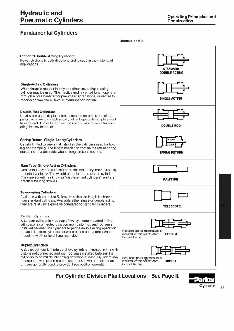
Fundamental Cylinders
Standard Double-Acting CylindersPowerstrokeisinbothdirectionsandisusedinthemajorityofapplications.
Operating Principles andConstruction
Illustration B29
Single-Acting Cylinders
Whenthrustisneededinonlyonedirection,asingle-actingcylindermaybeused.Theinactiveendisventedtoatmospherethrough a breather/lter for pneumatic applications, or vented toreservoirbelowtheoillevelinhydraulicapplication.
Double-Rod CylindersUsedwhenequaldisplacementisneededonbothsidesofthepiston,orwhenitismechanicallyadvantageoustocouplealoadtoeachend.Theextraendcanbeusedtomountcamsforoper-atinglimitswitches,etc.
Spring Return, Single-Acting Cylinders
Usuallylimitedtoverysmall,shortstrokecylindersusedforhold-ingandclamping.Thelengthneededtocontainthereturnspringmakesthemundesirablewhenalongstrokeisneeded.
Ram Type, Single-Acting Cylinders
Containing only one uid chamber, this type of cylinder is usuallymountedvertically.Theweightoftheloadretractsthecylinder.Theyaresometimesknowas“displacementcylinders”,andarepracticalforlongstrokes.
Telescoping Cylinders
Availablewithupto4or5sleeves;collapsedlengthisshorterthanstandardcylinders.Availableeithersingleordouble-acting,theyarerelativelyexpensivecomparedtostandardcylinders.
Tandem Cylinders
Atandemcylinderismadeupoftwocylindersmountedinlinewithpistonsconnectedbyacommonpistonrodandrodsealsinstalledbetweenthecylinderstopermitdoubleactingoperationofeach.Tandemcylindersallowincreasedoutputforcewhenmountingwidthorheightarerestricted.
Duplex Cylinders
Aduplexcylinderismadeupoftwocylindersmountedinlinewithpistonsnotconnectedandwithrodsealsinstalledbetweenthecylinderstopermitdoubleactingoperationofeach.Cylindersmaybemountedwithpistonrodtopiston(asshown)orbacktobackandaregenerallyusedtoprovidethreepositionoperation.
Reducedoperatingpressureisrequiredforthisconstruction.Contactfactory.
Reducedoperatingpressureisrequiredforthisconstruction.Contactfactory.
8/7/2019 Hydraulic Fundamental
http://slidepdf.com/reader/full/hydraulic-fundamental 4/52
Hydraulic andPneumatic Cylinders
For additional information – call your local Parker Cylinder Distributor.
2
DisplacementPer InchOf Stroke
(Gallons).00340
.00765
.0136
.0213
.0359
.0544
.0850
.1224
.1666
.2176
.3400
.4896
.6664
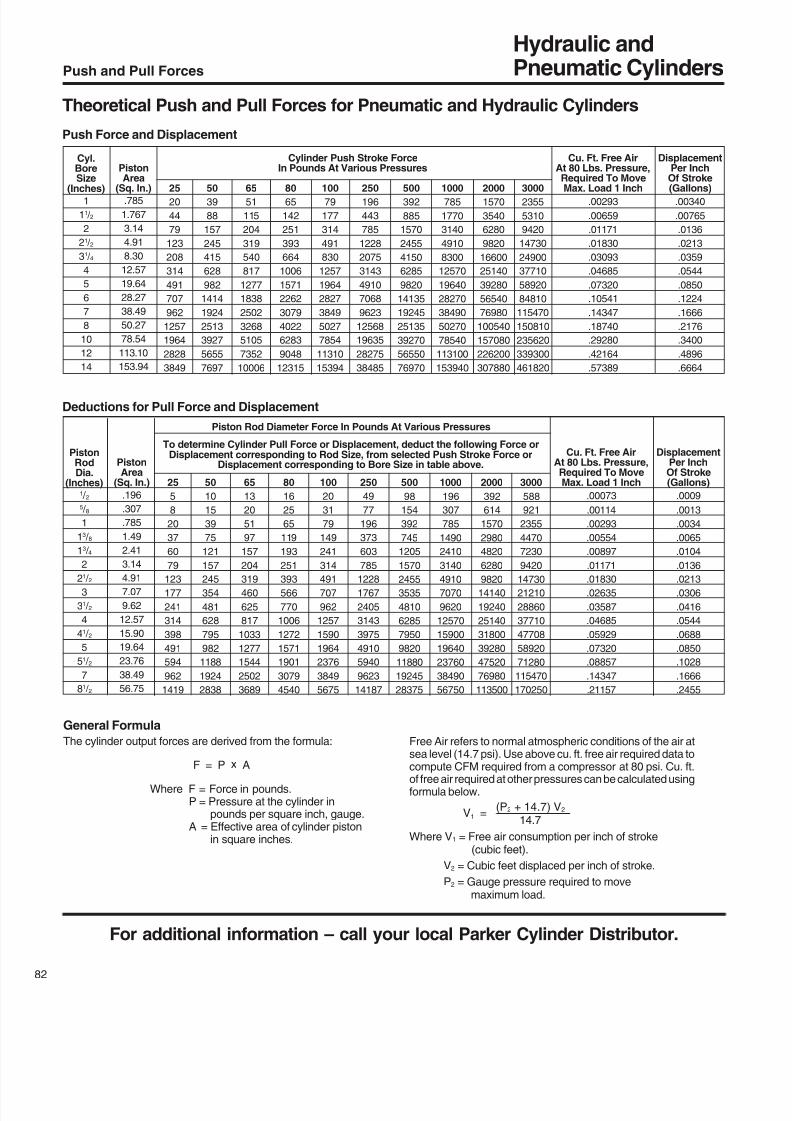
Push and Pull Forces
Theoretical Push and Pull Forces for Pneumatic and Hydraulic Cylinders
Push Force and Displacement
Cyl.BoreSize
(Inches)1
11 / 2
2
21 / 2
31 / 4
4
5
6
7
8
10
12
14
PistonArea
(Sq. In.).785
1.767
3.14
4.91
8.30
12.57
19.64
28.27
38.49
50.27
78.54
113.10
153.94
Cu. Ft. Free AirAt 80 Lbs. Pressure,Required To Move
Max. Load 1 Inch.00293
.00659
.01171
.01830
.03093
.04685
.07320
.10541
.14347
.18740
.29280
.42164
.57389
Cylinder Push Stroke ForceIn Pounds At Various Pressures
2520
44
79
123
208
314
491
707
962
1257
1964
2828
3849
5039
88
157
245
415
628
982
1414
1924
2513
3927
5655
7697
6551
115
204
319
540
817
1277
1838
2502
3268
5105
7352
10006
8065
142
251
393
664
1006
1571
2262
3079
4022
6283
9048
12315
10079
177
314
491
830
1257
1964
2827
3849
5027
7854
11310
15394
250196
443
785
1228
2075
3143
4910
7068
9623
12568
19635
28275
38485
500392
885
1570
2455
4150
6285
9820
14135
19245
25135
39270
56550
76970
1000785
1770
3140
4910
8300
12570
19640
28270
38490
50270
78540
113100
153940
20001570
3540
6280
9820
16600
25140
39280
56540
76980
100540
157080
226200
307880
30002355
5310
9420
14730
24900
37710
58920
84810
115470
150810
235620
339300
461820
Deductions for Pull Force and Displacement
General Formula
The cylinder output forces are derived from the formula:
F = P x A
Where F = Force in pounds.P = Pressure at the cylinder in
pounds per square inch, gauge.A = Effective area of cylinder piston
in square inches.
Free Air refers to normal atmospheric conditions of the air atsea level (14.7 psi). Use above cu. ft. free air required data to
compute CFM required from a compressor at 80 psi. Cu. ft.of free air required at other pressures can be calculated usingformula below.
(P2 + 14.7) V2
V1 =
14.7
Where V1 = Free air consumption per inch of stroke(cubic feet).
V2 = Cubic feet displaced per inch of stroke.
P2 = Gauge pressure required to movemaximum load.
PistonArea
(Sq. In.)
.196
.307
.785
1.49
2.41
3.14
4.917.07
9.62
12.57
15.90
19.64
23.76
38.49
56.75
PistonRodDia.
(Inches)1 / 25 / 8
1
13 / 8
13 / 4
2
21 / 2
3
31 / 2
4
41 / 2
5
51 / 2
7
81 / 2
25
5
8
20
37
60
79
123
177
241
314
398
491
594
962
1419
50
10
15
39
75
121
157
245
354
481
628
795
982
1188
1924
2838
65
13
20
51
97
157
204
319
460
625
817
1033
1277
1544
2502
3689
80
16
25
65
119
193
251
393
566
770
1006
1272
1571
1901
3079
4540
100
20
31
79
149
241
314
491
707
962
1257
1590
1964
2376
3849
5675
250
49
77
196
373
603
785
1228
1767
2405
3143
3975
4910
5940
9623
14187
500
98
154
392
745
1205
1570
2455
3535
4810
6285
7950
9820
11880
19245
28375
DisplacementPer InchOf Stroke(Gallons)
.0009
.0013
.0034
.0065
.0104
.0136
.0213
.0306
.0416
.0544
.0688
.0850
.1028
.1666
.2455
Cu. Ft. Free AirAt 80 Lbs. Pressure,Required To MoveMax. Load 1 Inch
.00073
.00114
.00293
.00554
.00897
.01171
.01830
.02635
.03587
.04685
.05929
.07320
.08857
.14347
.21157
1000
196
307
785
1490
2410
3140
4910
7070
9620
12570
15900
19640
23760
38490
56750
2000
392
614
1570
2980
4820
6280
9820
14140
19240
25140
31800
39280
47520
76980
113500
3000
588
921
2355
4470
7230
9420
14730
21210
28860
37710
47708
58920
71280
115470
170250
Piston Rod Diameter Force In Pounds At Various Pressures
To determine Cylinder Pull Force or Displacement, deduct the following Force orDisplacement corresponding to Rod Size, from selected Push Stroke Force or
Displacement corresponding to Bore Size in table above.
8/7/2019 Hydraulic Fundamental
http://slidepdf.com/reader/full/hydraulic-fundamental 5/52
Hydraulic andPneumatic Cylinders
For Cylinder Division Plant Locations – See Page II.
Operating Fluids and Temperature RangeFluidpower cylinders are designed for use with pressurized air, hydraulic oil and fire resistantfluids, in some cases special seals are required.
Standard Seals (class 1)Class 1 seals are what is normally provided in a cylinder unless otherwise specified. They areintended for use with fluids such as: air, nitrogen, mineral base hydraulic oil or MIL-H-5606within the temperature range of -10°F (-23°C) to +165°F (+74°C). Generally they are nitrileexcept for piston rod seals in hydraulic cylinders. However the individual seals may be nitrile(Buna-N) enhanced polyurethane, polymyte, P.T.F.E. or filled P.T.F.E.
Water Base Fluid Seals (class 2)Generally class 2 seals are intended for use with water base fluids within the temperature of-10°F (-23°C) to +165°F (+74°C) except for High Water Content Fluids (H.W.C.F.) in whichcase Class 6 seals should be used. Typical water base fluids are: Water, Water-Glycol, Water-inEmulsion, Houghto-Safe 27, 620, 5040, Mobil Pyrogard D, Shell Irus 905, Ucon Hydrolube J-4.These seals are nitrile. Lipseal will have polymyte or P.T.F.E. back-up washer when required.O-rings will have nitrile back-up washers when required.
Ethylene Propylene (E.P.R.) Seals (class 3)Class 3 seals are intended for use with some Phosphate Ester Fluids between the temperaturesof -10°F (-23°C) to +130°F (+54°C). Typical fluids compatible with E.P.R. seals are Skydrol 500and 700. E.P.R. are Ethylene Propylene. Lipseals will have a P.T.F.E. back-up washer whenrequired. O-rings will have EPR back-up washers when required. Note: E.P.R. seals are notcompatible with mineral base hydraulic oil or greases. Even limited exposure to these fluids willcause severe swelling. P.T.F.E. back-up washer may not be suitable when used in a radiationenvironment.
Low Temperature Nitrile Seals (class 4)Class 4 seals are intended for low temperature service with the same type of fluids as used withClass 1 seals within the temperature range of -50°F (-46°C) to +150°F (+66°C). Lipseals willhave leather, polymyte or P.T.F.E. back-up washers when required. O-rings will have nitrileback-up washers when required. Note: Certain fluids may react adversely with Class 4 sealscompared to Class 1 seals.
Fluorocarbon Seals (class 5)Class 5 seals are intended for elevated temperature service or for some Phosphate Ester Fluidssuch as Houghto-Safe 1010, 1055, 1120; Fyrquel 150, 220, 300, 350; Mobile Pyrogard 42, 43, 53,and 55. Note: In addition, class 5 seals can be used with fluids listed below under standardservice. However, they are not compatible with Phosphate Ester Fluids such as Skydrols. Class5 seals can operate with a temperature range of -10°F (-23°C) to +250°F (+121°C). Class 5seals may be operated to +400°F (+204°C) with limited service life. For temperatures above+250°F (+120°C) the cylinder must be manufactured with non-studded piston rod and thread anda pinned piston to rod connection. Class 5 Lipseals will have P.T.F.E. back-up washers whenrequired. O-rings will have fluorocarbon back-up when required.
WarningThe piston rod stud and the piston rod to piston threaded connections are secured with ananaerobic adhesive which is temperature sensitive. Cylinders specified with Class 5 seals areassembled with anaerobic adhesive having a maximum temperature rating of +250°F (+74°C).Cylinders specified with all other seal compounds are assembled with anaerobic adhesivehaving a maximum operating temperature rating +165°F (+74°C). These temperature limitationsare necessary to prevent the possible loosening of the threaded connections. Cylinders originallymanufactured with class 1 seals (Nitrile) that will be exposed to ambient temperatures above+165°F (+74°C) must be modified for higher temperature service. Contact the factoryimmediately and arrange for the piston to rod and the stud to piston rod connections to be
properly re-assembled to withstand the higher temperature service.
H.W.C.F. Seals (class 6)Class 6 seals are intended for High Water Content Fluids (H.W.C.F.) such as HoughtoHydrolubic 120B and Sonsol Lubrizol within the temperature range of +40°F (+4°C) to +120°F(+49°C). Class 6 seals are special nitrile compound dynamic seals. Lipseals will have P.T.F.E.and or polymyte back-up washers when required. O-rings will have nitrile back-up washerswhen required. Because of the viscosity of these fluids, cylinders specified with class 6 seals,will also be modified to have lip seal piston seals and straight cushions.
Hi-Load SealsHi-load seals consist of one or two f illed PTFE dynamic piston seals with an elastomer expanderunderneath. Hi-load piston arrangement normally consists of a wear ring on each end of the
Operating Fluids and SealsTemperature Range/Water Service/WarrantyPre-Lubricated, Non-Lubricated Cylinders
piston with the seals in the middle. These types of seals are virtually leak free seals under staticconditions and can tolerate high pressure. The wear rings on the piston can also tolerate highside loads. The dynamic portion of the seal is bronze filled PTFE and compatible with allconditions and fluids listed on this page. However, carbon filled PTFE will provide better seal lifewhen used with class 6 fluids. A nitrile expander will be provided unless Class 3 or 5 seals arespecified. In those cases the expander will be of E.P.R. or fluorocarbon respectively. Note: It maybe necessary to cycle the piston seals 40 or 50 times before achieving leakage free performance.
Lipseal PistonsUnder most conditions lipseals provide the best all around service for pneumatic applications.Lipseals with a back-up washer are often used for hydraulic applications when virtually zero
static leakage is required. Lipseals will function properly in these applications when used inconjunction with moderate hydraulic pressures. A high load piston option is recommended whenoperating at high pressures and especially with large bore hydraulic cylinders.
Low Friction Hydraulic SealsLow Friction hydraulic seals are available as an option for both piston and rod seals for 2H, 3Hand 3L Series cylinders. They are sometimes used when a cylinder is controlled by servo orproportional valve. The seal assembly itself is a two piece assembly consisting of a filled PTFEdynamic seal with an elastomer expander. A piston seal assembly consists of one seal assemblyin the middle of the piston with a filled PTFE wear ring on each side of the piston. The piston rodseal assembly consists of two seal assemblies and an elastomer wiper seal. The filled PTFEseals are compatible with the fluids listed on this page and provide virtually leak free sealing. Theexpanders and rod wiper will be fluorocarbon unless E.P.R. or fluorocarbon seals are specified.In those cases the expanders and wiper will be E.P.R. and fluorocarbon respectively. Whenspecifying low friction seals specify if piston, piston rod seals or both are required. Note: It maybe necessary to cycle these seals 40 or 50 times before achieving leakage free performance.
Cast Iron Piston RingsCast iron rings are the standard piston seals for 2H and 3L Series cylinders. They offer thewidest operating conditions by tolerating high operating pressures, wide temperature range andare compatible with most fluids. The only drawback of cast iron rings is that they allow a smallamount of leakage. The leakage for a 4" bore cylinder, operating at 2000 psi, with mineral base
hydraulic fluid will be less than 10in3
/min. Leakage will increase as pressure, bore size andviscosity of the operating hydraulic fluid increases. For these reasons cast iron rings are notrecommended when using water or (H.W.C.F.) fluids.
Water ServiceFor 3L series cylinders can be modified to make them more suitable for use with water as theoperating medium. The modifications include chrome-plated cylinder bore; electroless nickel-plated head, cap and piston; chrome-plated 17-4 stainless steel piston rod; chrome platedcushion sleeve or cushion spear.
Modified cylinders may also be used for higher operating pressures, up to 2000 psi, depending onbore size. See pressure rating for Hydraulic Cylinders on the next page. 3L, 2H and 3H Serieshydraulic cylinders can also be modified for water operation and supplied with chrome-platedcylinder bore; electroless nickel-plated head, cap and piston; chrome-plated precipitationhardened stainless steel piston rod, chrome-plated cushion sleeve or cushion spear. When highwater base fluids are the operating medium, hydraulic cylinders are usually supplied with highwater base rod wiper and seals. Water and high water base fluid operated cylinders are bestused on short stroke applications or where high pressure is applied only to clamp the load.
WarrantyParker Hannifin will warrant cylinders modified for water or high water content fluid service to befree of defects in materials or workmanship, but cannot accept responsibility to premature failuredue to excessive wear due to lack of lubricity or where failure is caused by corrosion,
electrolysis or mineral deposits within the cylinder.Pre-Lubricated Air CylindersParker Hannifin air cylinders are factory pre-lubricated with Lube-A-Cyl applied to seals, piston,cylinder bore, piston rod and gland surfaces, provides for normal cylinder operations withlubricated air.
Non-Lubricated Air CylindersFor heavier duty operation, Series 2AN is recommended for non-lubricated air service. Series2AN includes an innovative special composite material wick and ring reservoir assembly in eachseal groove to retain the extreme pressure lubricant applied at time of assembly. This lubricantcoats the cylinder bore and piston rod and mating surfaces.
Temperature Range-10°F (-23°C) to+165°F (+74°C)
-10°F (-23°C) to+165°F (+74°C)
-10°F (-23°C) to+130°F (+54°C)
-50°F (-46°C) to+150°F (+66°C)
See above paragraph on Fluorocarbon sealsfor recommended temperature range.
+40°F (+4°C) to+120°F (+49°C)
Class No.1 (Standard)(Nitrile Polyurethane)
2 OptionalWater Base Fluid Seal
3 Special (E.P.R.) (At extra cost)
Note: (E.P.R.) seals are not compatible with Hydraulic Oil
4 Special (Nitrile) (At extra cost)
5 Optional (At extra cost)(Fluorocarbon Seals)
Note: Fluorocarbon seals are not suitable for use with Skydrol fluid, but can be used with hydraulic oil if desired
6 Optional (HWCF) (At extra cost)
Typical FluidsAir, NitrogenHydraulic Oil, Mil-H-5606 Oil
Water, Water-Glycol, H.W.C.F. — See Class 6 below.Water-in-Oil Emulsion Houghto-Safe, 271, 620, 5040Mobil Pyrogard D, Shell Irus 905Ucon Hydrolube J-4
Some Phosphate Ester FluidsSkydrol 500, 7000
Low Temperature Air or Hydraulic Oil
High TemperatureHoughto-Safe 1010, 1055, 1120Fyrquel 150, 220, 300, 550Mobil Pyrogard 42,43,53,55
Houghton, Hydrolubric 120BSonsol Lubrizol, for other HWCF — consult factory.
8/7/2019 Hydraulic Fundamental
http://slidepdf.com/reader/full/hydraulic-fundamental 6/52
Hydraulic andPneumatic Cylinders
For additional information – call your local Parker Cylinder Distributor.
4
*Applies to all mountings except J. See Series 3L
1
11 / 2
2
21 / 2
31 / 4
4
5
6
8
1900
1900
2000
2300
1100
2000
2000
700
1400
1400
1400
1300
1300
1300
1300
900
900
900
900
900600
950
950
950
950
950
950
700
700
700
700
700
700
700
400650
650
650
650
650
650
650
650
650
1 / 25 / 85 / 8
15 / 8
1
13 / 85 / 8
1
13 / 8
13 / 4
1
13 / 8
13 / 4
2
1
13 / 8
13 / 4
2
21 / 2
1
13 / 8
13 / 4
2
21 / 2
3
31 / 2
13 / 8
13 / 4
2
21 / 2
3
31 / 2
4
13 / 8
13 / 4
2
21 / 2
3
31 / 2
4
41 / 2
5
51 / 2
*Applies to all mountings except J and H. See Series 2H
5 / 8
1
1
13 / 8
13 / 4
2
21 / 2
3
31 / 2
2530
2950
2340
2250
2130
2170
2270
2030
2040
11 / 2
2
21 / 2
31 / 4
4
5
6
7
8
3000
3000
3000
3000
3000
3000
3000
3000
3000
Cylinder Pressure Ratings
Application Data
The proper application of a fluid power cylinder requires consid-eration of the operating pressure, the fluid medium, the mountingstyle, the length of stroke, the type of piston rod connection to
the load, thrust or tension loading on the rod, mounting attitude,the speed of stroke, and how the load in motion will be stopped.Information given here provides pressure rating data for pneu-matic and hydraulic cylinders.
Pneumatic CylindersStandard operating fluid — filtered air which is free of moisture.2A and 2AN Series cylinders are recommended for maximum250 psi heavy duty service; Series MA industrial cylinders maybe used at pressures up to 200 psi.
Pressure Ratings Fluid Medium Air
Hydraulic Cylinders (Heavy duty)Standard operating fluid - clean, filtered hydraulic oil. Pressureratings for heavy duty hydraulic cylinders are shown in thefollowing table:
Pressure Ratings
Series 2H, 3H (7" & 8"), VH and HD hydraulic cylinders arerecommended for pressures to 3000 p.s.i. for heavy-duty servicewith hydraulic oil. The 4:1 design factor ratings shown are basedon tensile strength of material and are for code 1 rod dia. only.The rating is conservative for continuous severe applications. De-sign factors at other pressures can be calculated from this rating.In addition, mounting styles, stroke, etc., should be consideredbecause of the limiting effect they may have on these ratings.
Maximum Pressure Ratings
Hydraulic Cylinders (Medium duty)Pressure ratings for “Series 3L” hydraulic cylinders vary by boresize and rod size as shown in table below. For pressures higherthan those indicated, Series 2H heavy duty cylinders should beused.
Series 3L Hydraulic Cylinders Maximum Pressure Rating
Bore Size(Inches)
1
11 / 2
2
21
/ 231 / 4
4
5
6
8
10
12
14
4:1*Design Factor(Tensile) (PSI)
Bore Size(Inches)
RodDiameter(Inches)
Heavy-DutyService
(PSI)
Pressure RatingAt 4:1 Design*
Factor(On Tensile)Bore Size
RodDiameters
StandardPiston RodDiameters(Inches)
1 / 2
5 / 8
5 / 8
5
/ 81
1
1
13 / 8
13 / 8
13 / 4
2
21 / 2
Series 2A, 2ANMax. Heavy-Duty
Operating Pressure(PSI)
250
250
250
250250
250
250
250
250
250
250
250
Series MAMaximumOperating
Pressure (PSI)
—
200
200
200200
200
200
—
—
—
—
—
1
2
1
2
1
3
2
7
1
3
2
1
3
4
2
7
1
3
4
27
8
1
3
4
5
2
7
1
3
4
5
6
2
78
1
3
4
5
6
9
0
2
RodNo.
8/7/2019 Hydraulic Fundamental
http://slidepdf.com/reader/full/hydraulic-fundamental 7/52
Hydraulic andPneumatic Cylinders
For Cylinder Division Plant Locations – See Page II.
Group 1
Group 2
Group 3
Mounting Information
Single rod type, fluid power cylinders are commonly available in 20 standard mountingstyles ranging from head or cap end mounts to intermediate mounts. Many mountingstyles are also available in double rod type cylinders. Refer to NFPA Std. B93.15-1981 orParker air or hydraulic cylinder catalogs for detailed description.
Standard mounting styles for fluid power cylinders fall into three basic groups. The groupscan be described as follows.
Group 1 – Straight line force transfer with fixed mounts which absorb force on cylindercenterline.
Group 3 – Straight line force transfer with fixed mounts which do not absorb force oncylinder centerline.
Group 2 – Pivot force transfer with pivot mounts which absorb force on cylindercenterline and permit cylinder to change alignment in one plane.
Cylinder mounting directly affects the maximum pressure at which the fluid powercylinder can be used, and proper selection of mounting style will have a bearing oncylinder operation and service life. Whether the cylinder is used in thrust or tension, itsstroke length, piston rod diameter and the method of connection to load also must beconsidered when selecting a mounting style.
Fluidpower cylinders are offered for use with air pressure up to 250 psi; medium-dutyhydraulic, depending on bore size, up to 2200 psi; and heavy-duty hydraulic service of up
to 3000 psi. The industrial tie rod types, known as NFPA cylinders, with square steelheads and caps, plus steel mountings lend themselves to standardized mounts whichare similar in appearance for both air and hydraulic cylinders.
Because of the all steel construction, Parker air cylinders have a design factor of betterthan 4:1, and the various mounts can be used without limitations up to the cylindermanufacturer’s maximum rated pressure. Medium-duty and heavy-duty hydrauliccylinders, in some mounting styles, may not be used at full rated pressure, depending onmounting style, stroke length and thrust or tension loading, as discussed in the following:
Straight Line Force Transfer (Group 1)
Cylinders with fixed mounts (Group 1) which absorb the force on centerline are consid-ered the best for straight line force transfer. Tie rods extended, flange or centerline lugmounts are symmetrical and allow the thrust or tension forces of the piston rod to bedistributed uniformly about the cylinder centerline. Mounting bolts are subjected to simpletension or simple shear without compound forces, and when properly installed damaging
cylinder bearing sideloading is kept to a minimum.Tie Rods Extended are considered to be of the centerline mount type. The cylinder tierods are designed to withstand maximum rated internal pressure and can be extendedand used to mount the cylinder at cap or head end. This often overlooked mounting willsecurely support the cylinder when bolted to the panel or machine member to which thecylinder is mounted. The torque value for the mounting nuts should be the same as thetie rod nut torque recommended by the cylinder manufacturer. Cylinders are availablewith tie rod extended both ends. In such applications one end is used for mounting andthe opposite end to support the cylinder or to attach other machine components.
Tie rod mount cylinders may be used to provide thrust or tension forces at full ratedpressures.
Tie rods extended head end (Parker Style TB), cap end (Parker Style TC) or extendedboth ends (Parker Style TD) are readily available and fully dimensioned in Parker cylinderproduct catalogs.
Flange Mount cylinders are also considered to be centerline mount type and thus areamong the best mounts for use on straight line force transfer applications. The machinedesigner has a choice of three mounting styles at each end, such as head rectangularflange (Style J), head square flange (Style JB), head rectangular (Style JJ), cap rectan-gular flange (Style H), cap square flange (Style HB), and cap rectangular (Style HH).Selection of a flange mounting style depends, in part, upon whether the major forceapplied to the load will result in compression (push) or tension (pull) stresses of thecylinder piston rod. Cap end mounting styles are recommended for thrust loads (push),while head end mounting styles are recommended where the major load puts the pistonrod in tension (pull).
Tie rods extended head end,Style TB
Tie rods extended cap end,Style TC
Tie rods extended both ends,Style TD
J
JB
JJ
8/7/2019 Hydraulic Fundamental
http://slidepdf.com/reader/full/hydraulic-fundamental 8/52
Hydraulic andPneumatic Cylinders
For additional information – call your local Parker Cylinder Distributor.
6
Spacer Bars
JJ Mount
Fig. 3
Fig. 2
Fig. 1
Mounting Information
Flange mounts are best used when end face is mounted against the machine supportmember. (Fig. 1) This is especially true where head rectangular flange type (Style J) isused with major load in tension. In this mode, the flange is not subjected to flexure orbending stresses, nor are the mounting bolts stressed to unusually high levels. The useof head rectangular flange (Style J) mount with major load in compression (see Fig. 2) isnot recommended except on reduced pressure systems. The use of Style J mount incompression subjects the flange to bending and the mounting bolts to tension stresses,
which could result in early fatigue failure. For maximum allowable pressure with Style Jhead rectangular mount used for compression (push) or rear face of flange mounted, seepressure rating in product catalogs for medium- or heavy-duty hydraulic cylinders. Forapplications where push forces require full rated system pressure, head square flange(Style JB) or head rectangular (Style JJ) mounts are recommended. The best head stylemounting for either push or pull applications at full rated pressure is Style JJ.
Style JJ mount has the same mounting hole pattern and rectangular dimensions as theStyle J mount. To substitute the head rectangular Style JJ mount for the head rectangularflange, Style J mount, it is necessary to use spacers to fill in the cataloged “F” dimensionpreviously occupied by the “J” flange. The spacers are installed as shown in Fig. 3.
Cap flange mounts are also best used when end face is mounted against the machinesupport member. The use of cap rectangular flange mount, Style H, is not recommendedon applications where the major load is in tension (pull) except at reduced pressure. Formaximum allowable pressure with cap rectangular flange, Style H, used in tension
application (pull) or front of flange mounted, see maximum pressure rating in productcatalogs for medium- and heavy-duty hydraulic cylinders.
For applications where pull forces involved require full rated system pressure, cap squareflange, Style HB, or cap rectangular, Style HH, mounts are recommended. The best capstyle mounting for either push or pull applications at full rated pressure is the caprectangular Style HH.
The Style HH mount has the same mounting hole pattern and rectangular dimensions asthe Style H mount. To substitute the Style HH for Style H, it is necessary to use spacersor order a cylinder with piston rod extension to make up for the cataloged “F” dimensionpreviously occupied by the “H” flange.
Straight Line Force Transfer (Group 3)
Centerline Lug Mount cylinders are considered fixed mount types which absorb forceon centerline and are used on straight line force transfer applications. They are leastpopular of the fixed mount type cylinders. When used at higher pressures or under shockconditions, the lugs should be dowel-pinned to the machine. (See Page 109 for dowelpin uses for fixed mount cylinders.)
Side Mount cylinders are considered to be fixed mounts which do not absorb force ontheir centerline. Cylinders of this group have mounting lugs connected to the ends, andone style has side tapped holes for flush mounting. The plane of their mounting surfacesis not through the centerline of the cylinder, and for this reason side mounted cylindersproduce a turning moment as the cylinder applies force to the load. (Fig. 4) This turningmoment tends to rotate the cylinder about its mounting bolts. If the cylinder is not wellsecured to the machine member on which it is mounted or the load is not well-guided,this turning moment results in side load applied to rod gland and piston bearings. Toavoid this problem, side mount cylinders should be specified with a stroke length at leastequal to the bore size.
Shorter stroke, large bore cylinders tend to sway on their mountings when subjected toheavy loads, especially side end lug or side and angle mounts. (Fig. 5)
Side mount cylinders are available in several mounting styles, such as side lug (Style C),Side tapped (Style F), side end lug (Style G) and side end angle (Style CB). Of these, theside lug mount its the most popular and reliable, since the mounting lugs are welded tohead and cap to form an integral unit at each end.
Side tapped mount is the choice when cylinders must be mounted side by side atminimum center-to-center distance. Another narrow side mount style is the side end lugmount which has lugs threaded to the tie rods. Thus the end lugs serve a dual function ofholding the cylinder together and act as a means of mounting. This mounting style shouldbe used only on medium- to light-duty applications, because the end lugs are subjectedto compound stresses which could result in early failure.
Fig. 4
Fig. 5
F
G
CB
HB
H
L
H
aS1 b
F
S2T
E
HH
C
8/7/2019 Hydraulic Fundamental
http://slidepdf.com/reader/full/hydraulic-fundamental 9/52
Hydraulic andPneumatic Cylinders
For Cylinder Division Plant Locations – See Page II.
CLEVIS MOUNT CYLINDER
TRUNNION
MOUNT
CYLINDER
MAJOR LOAD IN TENSION
MAJOR LOAD IN THRUST
RIGHT
WRONG
Mounting Information
The side end angle mount is also a narrow mount type, but is the weakest of the sidemount styles. Its use should be limited to a maximum pressure of 500 psi and minimumstroke length of two times the bore size. For pressure rating of longer strokes, consult thecylinder manufacturer.
Consideration should also be given to design of the machine frame used to supportcylinders non-centerline mount, since stronger members are often required to resist
bending moments. (See Fig. 6)Side mount cylinders depend wholly on the friction of their mounting surfaces in contactwith the machine member to absorb the force produced. Thus the torque applied to themounting bolts is an important consideration. Since the mounting bolts are the samediameter as the tie rods for a given cylinder, it is recommended that the torque applied tothe mounting bolts be the same as the tie rod torque recommended by the cylindermanufacturer for the given bore size.
For heavy loads or high shock conditions, side mounted cylinders should be held in placeto prevent shifting by keying or pinning. A shear key, consisting of a plate extending fromside of cylinder, can be supplied on most cylinders. (Fig. 7) This method may be usedwhere a keyway can be milled into a machine member. It serves to take up shear loadsand also provides accurate alignment of the cylinder.
Side lug (and centerline lug) mounts are designed so as to allow dowel pins to be usedto pin the cylinder to the machine member. Pins, when used, are installed on both sides
of the cylinder but not at both ends. (See Fig. 8)The use of a separate shear key is fairly common. It should be placed at the proper endof the cylinder to absorb the major load. (see Fig. 9)
Side mount cylinders should not be pinned or keyed at both ends. Changes in tempera-ture and pressure under normal operating conditions cause the cylinder to increase (ordecrease) in length from its installed length and therefore must be free to expand andcontract. If pinned or keyed at both ends, the advantages of cylinder elasticity in absorb-ing high shock loads will be lost. (Fig. 10)
If high shock loads are the major consideration, the cylinder should be mounted and pinsor shear key so located as to take full advantage of the cylinder’s inherent elasticity. Formajor shock load in tension, locate key at rear face of head or pin the head in place. Formajor shock load in thrust, pin cap in place or locate key at front face of cap.
Pivot Force Transfer (Group 2)
Cylinders with pivot mounts which absorb force on centerline should be used onapplications where the machine member to be moved travels in a curved path. Thereare two basic ways to mount a cylinder so that it will pivot during the work cycle: clevis ortrunnion mounts, with variations of each. Pivot mount cylinders are available in cap fixedclevis (Style BB), cap detachable clevis (Style BC), cap spherical bearing (Style SB),head trunnion (Style D), cap trunnion (Style DB), and intermediate fixed trunnion (StyleDD).
Pivot mount cylinders can be used on tension (pull) or thrust (push) applications at fullrated pressure, except long stroke thrust cylinders are limited by piston rod columnstrength. See Piston Rod Selection Chart on Page 83.
Clevis or single ear mounts are usually an integral part of the cylinder cap (though onestyle is detachable) and provide a single pivot point for mounting the cylinder. A pivot pinof proper length and of sufficient diameter to withstand the maximum shear load devel-oped by the cylinder at rated operating pressure is included as a part of the clevis mount
style. The fixed clevis mount, Style BB, is the most popular of the pivot force transfertypes and is used on applications where the piston rod end travels in a curved path inone plane. It can be used vertically or horizontally or any angle in between. On longstroke push applications it may be necessary to use a larger diameter piston rod toprevent buckling or stop tube to achieve additional stability in the extended position.Fixed clevis mount cylinders will not function well if the curved path of piston rod travel isother than one plane. Such an application results in misalignment and causes the glandand piston bearing surfaces to be subjected to unnecessary side loading. For applica-tions where the piston rod will travel in a path not more than 3° either side of the trueplane motion, a cap spherical bearing mount is recommended. A spherical bearing rodeye should be used at rod end. Most spherical bearing mounts have limited pressureratings. Consult cylinder manufacturer’s product catalog.
8/7/2019 Hydraulic Fundamental
http://slidepdf.com/reader/full/hydraulic-fundamental 10/52
Hydraulic andPneumatic Cylinders
For additional information – call your local Parker Cylinder Distributor.
8
Spherical Bearing Mount
Fig. 11
D
DB
DD
Clevis Mount Cylinder
Fig. 12
1 "
–
–
–
1 1/2"
250
450
750
2"
250
400
700
2 1/2"
250
275
450
3 1/4"
250
375
625
4"
250
250
400
5"
150
150
250
6"
200
200
325
8"
125
125
200
Mounting Information
Cap detachable clevis mounts are usually not available in heavy-duty hydraulic cylinders.They are used more for air or medium hydraulic service. Cap detachable clevis mountsare longer, centerline of pivot pin to shoulder of piston rod, than fixed clevis mount in anygiven bore size. They are most often specified to avoid port relocation charges. Applica-tion parameters are the same as described for fixed clevis mounting.
Trunnion mount cylinders are a second type of pivot mounts used on applications where
the piston rod travels in a curved path in one plane. Three styles are available – headtrunnion (Style D), cap trunnion (Style DB) and intermediate fixed trunnion (Style DD).Trunnion pins are designed for shear loads only and should not be subjected to bendingstresses. Pillow blocks, rigidly mounted with bearings at least as long as the trunnionpins, should be used to minimize bending stresses. The support bearings should bemounted as close to the head, cap or intermediate trunnion shoulder faces as possible.
Cap end trunnion mounts are used on cylinder applications similar to fixed clevis mounts,and the same application data applies.
Head trunnion mount cylinders can usually be specified with smaller diameter piston rodsthan cylinders with pivot point at cap end or at an intermediate position. This is evident indata shown in the Piston Rod-Stroke Selection Chart. On head end trunnion mount, longstroke, cylinder applications consideration should be given to the overhanding weight atcap end of cylinder. To keep trunnion bearing loading within limits, stroke lengths shouldbe not more than 5 times the bore size. If cylinder stroke is greater than 5 times the boresize and piston speed exceeds 35 ft/minute, consult factory.
Intermediate fixed trunnion mount is the best of the trunnion mount types. The trunnioncan be located so as to balance the weight of the cylinder, or it can be located at any pointbetween the head or cap to suit the application. It is of fixed design, and the location of thetrunnion must be specified (XI dimension) at time of order. The location cannot be easilychanged once manufactured.
Thrust exerted by a pivot transfer cylinder working at an angle is proportional to the angleof the lever arm which it operates. In Fig. 12 that vector force, T, which is at right angle tothe lever axis, is effective for turning the lever. The value of T varies with the acute angle Abetween cylinder centerline and lever axes. To calculate effective thrust T, multiply cylinderthrust by the power factor shown in table below.
Accessories
Rod clevises or rod knuckles are available for use with either fixed or pivot mountcylinders. Such accessories are usually specified with pivot mount cylinders and are used
with pivot pin centerline in same axis as pivot pin centerline on cylinder. Pivot pins foraccessories must be ordered separately.
Pin size of rod clevis or rod knuckle should be at least equal in diameter to the pindiameter of the cap fixed clevis pin for the cylinder bore sizespecified. Larger accessories are more costly and usuallyresult in a mis-match of pin diameters, especially when usedwith oversize piston rods.
Removable Trunnion Pins
Removable trunnion pins are a convenience when machinestructures or confined space prohibit the use of separate pillowblocks situated close to the cylinder sides. Parker offers aremovable pin design in 1-1/2" through 8" bores sizes. (Seefollowing table for recommended maximum operating pres-sure.) Mounting pin diameters and lengths are identical to
those in Mounting Styles D and DB for any given bore size.These removable trunnion pins can be provided on the capend (Style DBR) of Series “2A” cylinders with any rod diameter.They can also be provided on the head end (Style DR) of cylinders with standard rods.
Power Factor Table
Pressure Ratings – Removable Trunnion Pin Mounting
Angle ADegrees
5
10
15
20
25
30
35
40
45
Pwr.Factor(SIN A)
0.087
0.174
0.259
0.342
0.423
0.500
0.573
0.643
0.707
Angle ADegrees
50
55
60
65
70
75
80
85
90
Pwr.Factor(SIN A)
0.766
0.819
0.867
0.906
0.940
0.966
0.985
0.996
1.000Bore Size
Std. Pressure Rating (PSI)
Extreme Pressure Rating
Hydraulic Rating (PSI)
LeverArm
Angle° (A)
T EffectiveThrust
FCylinderThrust
8/7/2019 Hydraulic Fundamental
http://slidepdf.com/reader/full/hydraulic-fundamental 11/52
Hydraulic andPneumatic Cylinders
For Cylinder Division Plant Locations – See Page II.
1
2
3
4
PortsParker hydraulic and pneumatic cylinders can be supplied withS.A.E. straight O-ring ports or N.P.T.F. pipe thread ports. For thetype of port recommended and port size, see respective productcatalogs. If specified on your order, extra ports can be providedon the sides of heads or caps that are not occupied by mount-ings or cushion valve on all cylinders except Series C and S.
Standard port location is position 1 as shown on line drawings inproduct catalog and Figure 1 below. Cushion adjustment needleand check valves are at positions 2 and 4 (or 3), depending onmounting style. Heads or caps which do not have an integralmounting can be rotated and assembled with ports at 90° or180° from standard position. Mounting styles on which head orcap can be rotated at no extra charge are shown in Table Abelow. To order, specify by position number. In such assembliesthe cushion adjustment needle and check valve rotate accord-ingly, since their relationship with port position does not change.
Figure 1
Port Position Available
Mounting Style Head End Cap End
T, TB, TC, TD, BC, CB,
H, HB, J, JB, 1, 2, 3 or 4 1, 2, 3 or 4DD
BB, DB, HH 1,2, 3 or 4 1 or 3
D, JJ 1 or 3 1, 2, 3 or 4
C, E, F, G 1 1
Ports
Ports can be supplied at positions other than those shown in
Table A at an extra charge. To order, specify port position asshown in Figure 1.
Cylinder Port OptionsOption “T” SAE Straight Thread O-Ring Port. Recommended
for most hydraulic applications.
Option “U” Conventional NPTF Ports (Dry-Seal Pipe Threads).Recommended for pneumatic applications only.
Option “R” BSPP Port (British Parallel Thread). ISO 228 portcommonly used in Europe. See Figure R-G on pg.C-115.
Option “P” SAE Flange Pots Code 61 (3000 psi).Recommended for hydraulic applications requiringlarger port sizes.
Option “B” BSPT (British Tapered Thread).
Option “G” Metric Straight Thread Port similar to Option “R”with metric thread. Popular in some Europeanapplications. See Figure R-G on pg. C-115.
Option “Y” ISO-6149-1 Metric Straight Thread Port.
Recommended for all hydraulic applicationsdesigned per ISO standards. See Figure Y on pg.C-115.
Available Ports for 2H, 3H, HD Series Cylinders
Available Ports for 2A and 3L Series Cylinders
Head (Rod) End Head Cap
Table A
Bore1 1/2
22 1/23 1/4
45678
“G” MetricStraight Thread
M22 x 1.5M22 x 1.5M22 x 1.5M27 x 2M27 x 2M27 x 2M33 x 2M42 x 2M48 x 2
“Y” ISO-6149-1Metric Straight Thread
M22 x 1.5M22 x 1.5M22 x 1.5M27 x 2M27 x 2M27 x 2M33 x 2M42 x 2M48 x 2
“B” BSPTTaper Thread
1/21/21/23/43/43/41
1 1/41 1/2
“P” SAE 4-BoltFlange Nom. Size
N/AN/A1/23/43/43/41
1 1/41 1/2
“U” NPTFPipe Thread
1/21/21/23/43/43/41
1 1/41 1/2
“R” BSPPParallel Thread
1/21/21/23/43/43/41
1 1/41 1/2
“T” SAEStandard
#10#10#10#12#12#12#16#20#24
*Not available on code 2 rods
Bore1
1 1/22
2 1/23 1/4
4568
“G” MetricStraight Thread
M14 x 1.5M14 x 1.5M14 x 1.5M14 x 1.5M22 x 1.5M22 x 1.5M22 x 1.5M26 x 1.5M26 x 1.5
“Y” ISO-6149-1Metric Straight Thread
M14x 1.5*M14 x 1.5*M14 x 1.5M14 x 1.5M22 x 1.5M22 x 1.5M22 x 1.5M27 x 2M27 x 2
“U” NPTFPipe Thread
1/43/83/83/81/21/21/23/43/4
“R” BSPPParallel Thread
1/43/83/83/81/21/21/21/23/4
“T” SAEStandard
#6#6#6#6
#10#10#10#12#12
Applies to Series MA, MAN, 2A, 2AN, 3L, DH, 3H, VH and HD.
“B” BSPTTaper Thread
1/43/83/83/81/21/21/21/23/4
8/7/2019 Hydraulic Fundamental
http://slidepdf.com/reader/full/hydraulic-fundamental 12/52
Hydraulic andPneumatic Cylinders
For additional information – call your local Parker Cylinder Distributor.
0
Y
A DIA.
X
GG
P + STROKE
Z UNC-2B THD.AA MIN.DEPTH4 HOLES
Q
W
RodCode
1
1231231234AllAllAll
A.50
.75
.75
.75
1.001.251.50
SAEDashNo.
8
12
12
12
162024
11 / 16 - 12
—
15 / 16 - 12
15 / 8 - 12
17 / 8 - 12
21 / 2 - 12
—
.383
.518
.656
.825
1.041
1.309
1.6501.882
2.347
Straight Thread Ports
The S.A.E. straight thread O-ring port is recommended forhydraulic applications. Parker will furnish this port configurationat positions shown in Table A on page C111. This port can alsobe provided at positions other than those shown in Table A at anextra charge. S.A.E. port size numbers are listed next to their
N.P.T.F. pipe thread counterparts for each bore size in therespective product catalogs. Size number, tube O.D. and portthread size for S.A.E. ports are listed in Table C.
Table CS.A.E. Straight Thread “O” Ring Ports
Size Tube Thread Size Tube ThreadNo. O.D. (In.) Size No. O.D. (In.) Size
Note: For the pressure ratings of individual connectors, contactyour connector supplier. Hydraulic cylinders applied with meter outor deceleration circuits are subject to intensified pressure at thecylinder piston rod end. The rod end pressure is approximatelyequal to:
effective cap end piston areaeffective rod end piston area
x Operating Pressure
International Ports
Other port configurations to meet international requirements areavailable at extra cost. Parker cylinders can be supplied, onrequest, with British standard taper port (BSPT). Such port has ataper of 1 in 16 measured on the diameter (1 / 16" per inch). The
thread form is Whitworth System, and size and number of threadsper inch are as follows:
Table D
British Standard Pipe Threads
British standard parallel internal threads are designated as BSP andhave the same thread form and number of threads per inch as theBSPT type and can be supplied, on request, at extra cost. Unlessotherwise specified, the BSP or BSPT port size supplied will be thesame nominal pipe size as the N.P.T.F. port for a given bore sizecylinder.
Metric ports options G or Y can also be supplied to order at extracost.
1 / 8
1 / 4
3 / 8
1 / 2
3 / 4
1
11
/ 411 / 2
2
1 / 8"3 / 16"1 / 4"5 / 16"3 / 8"1 / 2"5 / 8"
12
—
16
20
24
32
—
3 / 4"
—
1"
11 / 4"
11 / 2"
2"
—
2
3
4
5
6
8
10
5 / 16 - 243 / 8 - 24
7 / 16 - 201 / 2 - 20
9 / 16 - 183 / 4 - 167 / 8 - 14
28
19
19
14
14
11
1111
11
Nominal No. Threads PipePipe Size Per Inch O.D.
Ports
BSPP or Metric Portoptions “R” and “G” forSeries 3L, 2H, 3H, HD
ISO 6149-1Port option “Y” forSeries 3L, 2H, 3H, HD
Figure R-G Figure Y
Flange Ports (Code 61, 3000 psi)
SAE 4 Bolt Flange Ports for 2H, 3H (7"-8"), HD
BoreSize
2 1/2*†
3 1/4†
4†
5†
678
Y2.39
2.773.143.023.023.393.143.143.393.393.393.523.773.91
W.75
.94
.94
.94
1.031.161.37
Q1.50
1.87
1.87
1.87
2.062.312.75
X.34
.44
.44
.44
.52
.59
.70
*2 1/2" bore head, flange port available with code 1 & 3 rod only.
†2 1/2", 3 1/4", 4" & 5" bores cap-flange port not available on HB mounting. H
mounting not available at position 2 or 4. Port flange overhangs cap on HHmounting.
RodCode
1
1231231234AllAllAll
AA.81
.75
.75
.75
.871.001.06
SAEDashNo.8
12
12
12
162024
BoreSize
2 1/2*†
3 1/4†
4†
5†
678
Z5/16 - 18
3/8 - 16
3/8 - 16
3/8 - 16
3/8 - 167/16 - 141/2 - 13
GG.69
.87
.87
.87
1.031.191.41
POSSIBLE TYPES OF SEALS
SEALING SURFACE
S U R F A C E Ò A Ó
I D E N T I F I C A T I O N M A R K O R
S U R F A C E Ò A Ó I S M A R K E D M E T R I C
P2.97
3.47
3.72
4.22
4.855.476.19
8/7/2019 Hydraulic Fundamental
http://slidepdf.com/reader/full/hydraulic-fundamental 13/52
Hydraulic andPneumatic Cylinders
For Cylinder Division Plant Locations – See Page II.
Oversize PortsOversize NPTF or SAE straight thread ports can be provided, at an extra charge, on pneumaticand hydraulic cylinders. For ports one size larger than standard, welded port bosses whichprotrude from the side of the head or cap are supplied. For dimensions, see drawings and tablesbelow. 2H and 3L cylinders equipped with cushions at the cylinder cap end can sustain damage tothe cushion check valve (cushion bushing) if excessive oil flow enters the cylinder from the capend port. Cylinders which are equipped with cap end cushions and ordered with one size oversizeports having hydraulic fluid flow exceeding 25 ft./sec. in the line entering the cap end of thecylinder should be ordered with a “solid cushion” at cap end such as provided with the “VH”Series. All cylinders ordered with double oversize ports should always be ordered with a “solid
cushion” at cap end such as provided with the “VH” Series.Cylinders which are connected to a meter out flow control with flow entering the cap end of acylinder provided by an accumulator may also experience damage to the cushion bushing due tohigh instantaneous fluid flows. This condition can be eliminated by using a meter in flow control or“solid cushions” at cap end such as provided with the “VH” Series.
Oversize NPTF Port Boss DimensionsSeries 2A, MA and 3L Cylinders
Series 2H, 3H (7" & 8"), HD Cylinders
Oversize SAE Straight Thread Port BossDimensionsSeries 3L Cylinders
Series 2H, 3H (7" & 8"), HD Cylinders
Manifold PortsSide mounted cylinders, Style C can be furnished with the cylinder ports arranged for mountingand sealing to a maniforld surface. The ports are drilled and counterbored for O-ring seals whichare provided. With These specifications, the mounting is designated Style CM or KCM.
Dimensions —Manifold Ports for Single and Double Rod Cylinders
Series 2H, 3H (7" & 8"), HD Cylinders
Series 2A, 3L Cylinders
12123
1234
12341
23451
2, 6 & 7345
1
2, 5, 6, 7341
2, 5, 6, 7, 8, 9 & 03413
4, 5, 6, 7, 8, 9 & 01
3,4, 5, 6, 7, 8 & 9All
1
11 / 2
2
21 / 2
31 / 4
4
5
6
7 - 8
10
12
14
5 / 81
5 / 813 / 81
5 / 813 / 41
13 / 81
213 / 813 / 41
21 / 213 / 813 / 421
31 / 2, 21 / 2 & 3
13 / 813 / 42
13 / 84, 21 / 2, 3 & 31 / 2
13 / 42
13 / 851 / 2, 21 / 2, 3, 31 / 2, 4, 41 / 2 & 5
13 / 42
13 / 42
21 / 2, 3, 31 / 2,4, 41 / 2, 5 & 51 / 22
21 / 2, 3, 31 / 2,4, 41 / 2, 5 & 51 / 2All
Rod Code
Bore1
11 / 22
21 / 231 / 445
67-81012
14
EE (NPTF)3 / 81 / 21 / 21 / 23 / 43 / 43 / 411
11 / 411 / 411 / 2
A (Dia.)7 / 811 / 811 / 811 / 813 / 813 / 813 / 813 / 413 / 421 / 421 / 421 / 2
B3 / 4
15 / 16
15 / 16
15 / 16
111
13 / 16
13 / 16
15 / 16
15 / 16
19 / 16
C9 / 16
9 / 16
9 / 16
9 / 16
11 / 16
11 / 16
11 / 16
15 / 16
15 / 16
11 / 811 / 811 / 4
D1 / 21 / 21 / 21 / 25 / 85 / 85 / 83 / 43 / 411
11 / 8
P21 / 16
23 / 16
23 / 16
25 / 16
29 / 16
29 / 16
213 / 16
33 / 16
35 / 16
41 / 443 / 451 / 2
Bore11 / 22
21 / 231 / 445678
EE (NPTF)3 / 43 / 43 / 41
11
11 / 411 / 22
A (Dia.)13 / 813 / 8
13 / 813 / 413 / 413 / 421 / 421 / 23
B11
113 / 16
13 / 16
13 / 16
15 / 16
19 / 16
111 / 16
C3 / 43 / 43 / 4
29 / 32
29 / 32
29 / 32
11 / 813 / 811 / 2
D25 / 32
25 / 32
25 / 32
7 / 87 / 87 / 811 / 813 / 811 / 2
P229 / 32
229 / 32
31 / 32
317 / 32
325 / 32
49 / 32
51 / 853 / 461 / 2
Bore1
11 / 22
21 / 231 / 44568
EE (SAE)888812
121216†16†
A (Dia.)11 / 811 / 811 / 811 / 813 / 813 / 813 / 813 / 413 / 4
B15 / 16
15 / 16
15 / 16
15 / 16
1
11
13 / 16
13 / 16
C9 / 16
9 / 16
9 / 16
9 / 16
11 / 16
11 / 16
11 / 16
15 / 16
15 / 16
D1 / 21 / 21 / 21 / 25 / 85 / 85 / 83 / 43 / 4
P21 / 16
23 / 16
23 / 16
25 / 16
29 / 16
29 / 16
213 / 16
33 / 16
35 / 16
†Available at head end only. For cap end, consult factory.*Port tapped directly into head on these cylinders with code 1 rods.Rod code 2 and cap use port boss.**Port tapped directly into head and cap.
Bore11 / 22
21 / 231 / 445
678
EE (SAE)12*
12*12**1616
1620**24**NA
A (Dia.)13 / 813 / 8**
13 / 413 / 413 / 4******
B1
1**
13 / 16
13 / 16
13 / 16
******
C13 / 16
13 / 16
**7 / 87 / 87 / 8******
D25 / 32
25 / 32
**7 / 87 / 87 / 8******
P231 / 32
231 / 32
31 / 83 9 / 16
313 / 16
45 / 16
5 3 / 16
5 5 / 861 / 4
Bore
11 / 2
2
21 / 2
31 / 4
4
5
6
7
8
5 / 811
13 / 81
13 / 413 / 813 / 82
13 / 413 / 421 / 2
22
31 / 221 / 23
21 / 243
31 / 23
531 / 24
41 / 231 / 251 / 24
41 / 25
223 / 823 / 825 / 823 / 827 / 825 / 823 / 431 / 83
227 / 32
37 / 32
231 / 32
31 / 8
33 / 8
31 / 2
313 / 16
315 / 16
27 / 8
27 / 8
3
31 / 2
4
41 / 4
51 / 8
57 / 8
65 / 8
27 / 8
27 / 8
3
31 / 2
41 / 16
41 / 4
47 / 8
53 / 8
61 / 8
3 / 4
3 / 4
3 / 4
1
1
1
11 / 4
11 / 2
11 / 2
11 / 8
11 / 8
11 / 8
13 / 8
13 / 8
13 / 8
15 / 8
17 / 8
17 / 8
Bore Rod. Dia. (MM) Y+1/32 P+1/32 EEM
ED
1212
1231
2312
312341
2341
23451
2345
All All
2
23 / 82
25 / 823 / 82
27 / 823 / 825 / 827 / 16
31 / 16
211 / 16
215 / 16
27 / 16
35 / 16
211 / 16
215 / 16
31 / 16
27 / 16
35 / 16
211 / 16
215 / 16
31 / 16
213 / 16
37 / 16
31 / 16
33 / 16
213 / 16
37 / 16
31 / 16
33 / 16
31 / 831 / 431 / 231 / 431 / 2
313 / 16
115 / 16 21 / 8
21 / 8
21 / 8
21 / 4
25 / 8
25 / 8
27 / 8
31 / 8
31 / 4
41 / 8
45 / 8
51 / 2
3 / 8
1 / 2
1 / 2
1 / 2
5 / 8
5 / 8
5 / 8
7 / 8
7 / 8
13 / 16
13 / 16
19 / 16
11 / 16
13 / 16
13 / 16
13 / 16
15 / 16
15 / 16
15 / 16
13 / 16
13 / 16
11 / 2
11 / 2
17 / 8
Y+1/32 P+1/32 PK+1/32 EEM EDRod
CodeRod Dia.
MM
Ports
P + STROKE
EE PORTSIDE
A A
B
C D
8/7/2019 Hydraulic Fundamental
http://slidepdf.com/reader/full/hydraulic-fundamental 14/52
Hydraulic andPneumatic Cylinders
For additional information – call your local Parker Cylinder Distributor.
2
11 / 2
21 / 4
31 / 4
4
41 / 2
International Rod End Threads
Piston rod threads to meet international requirements areavailable at extra cost. Parker cylinders can be supplied withBritish standard fine (W) or metric (M). To order, specify in modelnumber. For dimensions, consult factory.
Special Rod EndsIf a rod end configuration other than the standard styles 4, 8 and9 is required, such special rod ends can be provided. Thedesignation “Style 3” is assigned to such specials and is incorpo-rated in the cylinder model number. To order, specify “Style 3” andgive desired dimensions for KK; A; LA, LAF, W, or WF. If otherwisespecial, send a dimensioned sketch.
Special Assemblies from Standard Parts
Each dimensioned drawing in this catalog has position numbersshown on the end view to identify the four sides of the cylinder.These aid in communications and simplify the writing of specifi-cations that cover changes in port positions, etc. Following areseveral suggested special assemblies that can be made up fromstandard parts.
a) By calling out the position numbers for the desired locationsfor head and cap ports, many mounting styles can beassembled with ports located at 90° or 180° from standard. Insuch special assemblies, the cushion needle and checkvalves are also repositioned since their relation with the portposition does not change.
b) The cushion needle valve is interchangeable with the checkvalve in the cylinder heads. The cushion needle valve can beassembled on side position 4 with the check valve on side 2for most mounting styles when the port is in the standardside position 1.
On mounting styles D, DB and DD, the cushion needle valvesare provided only on the side position 3 on the head or capwhich accommodates the mounting. The opposite head orcap can be rotated.
c) Standard mountings in different combinations can beprovided: for example Style J mounting on head end withStyle C on the cap end. This would be made up fromstandard parts and would be designated Model JC-2HU14A.
Single-Acting Cylinders
Double-acting cylinders are supplied as standard. They can alsobe used a single-acting cylinders where fluid force is applied toonly one side of the piston, with the load or other external forcesacting to “return” the piston after pressure is exhausted.
Spring-Returned, Single-Acting Cylinders – Single-acting,spring-returned models can also be provided. Load conditionsand friction factors must be considered in supplying the properspring for the application. In addition, it is necessary that informa-
tion be supplied as to which side of the piston the spring shouldact upon. Specify "Spring to return piston rod” or “Spring toadvance piston rod.”
On longer stroke spring-returned cylinders, it is recommendedthat tie rod extensions be specified on the cylinder end in whichthe spring is located so that the cap or head against which thespring is acting can be “backed-off” slowly until compression ofthe spring is relieved. In such cases it should also be specifiedthat the tie rod nuts be welded to the tie rods at the opposite endof the cylinder to further insure safe disassembly.
Consult factory when ordering spring-returned cylinders.
Rod End DataPiston RodsSpecial Assemblies
Rod End Data
Rod end dimension symbols as shown comply with theNational Fluid Power Association dimensional code. Thefollowing chart indicates the symbols used in this catalog.
Description Symbol
Thread diameter and pitch KK or CC
Length of thread A
Length of rod extension from LA or LAF (Male Thread)face of gland retainer to end of W or WF (Female Thread)retracted rod
Three rod ends for Parker cylinders are offered as shown on thedimension pages of this catalog. They are Parker styles 4, 8and 9, and all three are optional without price penalty. If a rodend style is not specified, the Parker style 4 (N.F.P.A. Style SM)will be supplied. Styles 4 and 8 are supplied with high strengthrolled thread studs on piston rods through 2" diameter. Longerstuds in Parker Standard sizes are available, see table below.
Warning!Piston rods are not normally designed to absorb bendingmoments or loads which are perpendicular to the axis of pistonrod motion. These additional loads can cause the piston rod endto fail. If these types of additional loads are expected to beimposed on the piston rods, their magnitude should be madeknown to our Engineering Department so they may be properlyaddressed. Additionally, cylinder users should always make surethat the piston rod is securely attached to the machine member.
On occasion cylinders are ordered with double rods. In somecases a stop is threaded onto one of the piston rods and usedas an external stroke adjuster. This can cause a potential safetyconcern and can also lead to premature piston rod failure. Theexternal stop will create a pinch point and the cylinder usershould consider appropriate use of guards. If an external stop isnot parallel to the final contact surface it will place a bendingmoment on the piston rod. An external stop will also negate theeffect of a cushion and will subject the piston rod to an impactloading. These two (2) conditions can cause piston rod failure.The use of external stroke adjusters should be reviewed withour Engineering Department.
Piston Rod End Threads
Standard piston rod end thread lengths are shown as dimen-sion “A” in Catalog dimension pages. Special rod end threadswhich are two times standard length can be supplied at a smallextra cost. Available thread lengths are shown in the tablebelow. To order, add suffix “2” to piston rod model number codeand specify as Style #42 or Style #82.
Optional Piston Rod End Studs
7 / 16 - 203 / 4 - 16
1 - 14
11 / 4 - 12
11 / 2 - 12
Rod End ThreadStyle #42
Rod End ThreadStyle #82
11 / 2
21 / 4
31 / 4
4
41 / 2
1 / 2 - 207 / 8 - 14
11 / 4 - 12
11 / 2 - 12
13 / 4 - 12
5 / 8
1
13 / 8
13 / 4
2
ThreadDia. & Pitch
(KK)Length
( = 2 x A)
ThreadDia. & Pitch
(CC)Length(= 2 x A)Piston Rod Dia.
8/7/2019 Hydraulic Fundamental
http://slidepdf.com/reader/full/hydraulic-fundamental 15/52
Hydraulic andPneumatic Cylinders
For Cylinder Division Plant Locations – See Page II.
P D o
r
P E P
A
W
INTEGRAL KEYFT
STOP PINSEAL FOR THREADS 1" & UP
D-THREADS
J-WRENCH
SQUARE
SEAL FOR 1 / 2& 3 / 4 THREADS
K (MIN.)L
P D o r
P E P
A
W
INTEGRAL KEYFA
Series 2H, 3H (7" & 8"), VH Cylinders
Dim. PE
Mtg. StyleCBP
19 / 16
2
21 / 4
215 / 16
31 / 4
41 / 8
43 / 4
57 / 16
6
Thrust Key Mountings
Dim. PD
Mtg. StylesCBP*
13 / 16
13 / 8
15 / 8
113 / 16
21 / 4
29 / 16
31 / 16
35 / 8
Dim.FA
+.000.312 -.002
+.000.562 -.002
+.000.562 -.002
+.000.687 -.003
+.000.812 -.003
+.000.812 -.003
+.000.937 -.003
+.000.937 -.003
+.000.937 -.003
Stroke DataParker cylinders are available in any practical stroke length. Thefollowing information should prove helpful to you in selectingthe proper stroke for your cylinder application.
Stroke Tolerances – Stroke length tolerances are required dueto build-up of tolerances of piston, head, cap and cylinder body.Standard production stroke tolerances run +1 / 32" to -1 / 64" up to20" stroke, +1 / 32" to -.020" for 21" to 60" stroke and +1 / 32" to -1 / 32"for greater than 60" stroke. For closer tolerances on strokelength, it is necessary to specify the required tolerance plus theoperating pressure and temperature at which the cylinder willoperate. Stroke tolerances smaller than .015" are not generallypractical due to elasticity of cylinders.If machine design requires suchclose tolerances, use of astroke adjuster (below) mayachieve the desired result.
Tie Rod SupportsRigidity of Envelope – The pre-stressed tie rod construction ofParker cylinders has advantages in rigidity within the limits ofthe cylinder tube to resist buckling. For long stroke cylinders
within practical limits. Parker provides exclusive TIE RODSUPPORTS (see table below) which move the tie rodcenterlines radially outward (patent number 3011844).
Standard tie rod supports are kept within the envelope dimen-sions of the head and cap, and generally do not interfere withmounting a long cylinder.
Note: 5" through 14" bore sizes — no supports required.
Stroke AdjustersStroke Adjusters – For the requirement where adjusting thestroke is specified. Parker has several designs to offer, one ofwhich is illustrated below. This is suitable for infrequent adjust-ment and is economical.*
Here a “retracting stroke adjuster” must be called for in specifi-cations, and the length of the adjustment must be specified .
Where frequent adjustment or cushions at the cap end arerequired, other designs are available according to applicationneeds.
*Infrequent is defined by positioning the retract stroke in a couple ofattempts at original machine set up. The frequent stroke adjuster isrecommended for adjustments required after the original equipmenthas been adjusted by the original machine manufacturer.
Thrust Key Mountings
Thrust key mountings eliminate the need of using fitted bolts orexternal keys on side mounted cylinders. Parker cylinders inmounting styles CP, FP, GP and CBP can be provided with thegland retainer plate extended below the mounting side of thecylinder (see illustration below). This extended retainer plate canthen be fitted into a keyway milled into the mounting surface ofthe machine member. This is referred to as the “P” Modificationof any side mounting style.
Series 2A, 2AN and 3L
17 / 16
113 / 16
21 / 16
25 / 8
215 / 16
311 / 16
41 / 4
43 / 4
51 / 4
108
2
1
1
—
—
120
2
2
1
1
—
132
3
2
1
1
—
144
3
2
1
1
1
156
3
2
2
1
1
168
4
3
2
1
1
11 / 2”
2”
21 / 2”, 31 / 4”
4”
5”
6”
7”8”
11 / 2, 2
21 / 2,31 / 4,4
5, 6
8
10
12, 14
——
Bore
1
11 / 2
2
21 / 2
31 / 4
4
Stroke DataTie Rod SupportsStroke Adjusters-Thrust Key Mountings
Stroke (Inches)
36
—
—
—
—
—
—
48
1
—
—
—
—
—
60
1
1
—
—
—
—
72
1
1
1
—
—
—
84
2
1
1
—
—
—
96
2
1
1
—
—
N u m b e r o f
S u p p o r t s R e q u i r e d
Bore Size
Series2A-MA
3L
Series2H, VH
HD/HDC
5 / 16
7 / 16
5 / 8
15 / 16
15 / 16
111 / 16
223 / 8
J
5
8
9
18
20
20
2020
L(Max.)
15 / 16
11 / 4
111 / 16
21 / 8
211 / 16
31 / 8
31 / 4
31 / 2
K
1 / 2 - 20
3 / 4 - 16
1 - 14
11 / 2 - 12
2-12
21 / 2 - 12
3-1231 / 2 - 12
D
Consult Factory
17 / 16
113 / 16
21 / 16
25 / 8
215 / 16
311 / 16
41 / 4
51 / 4
Dim. PDMtg.
StylesCP, FP
& GP
Dim.
PA
3 / 16
5 / 16
3 / 8
Bore
1
11 / 2
2
21 / 2
31 / 4
4
5
6
15 / 16
13 / 16
17 / 16
111 / 16
23 / 16
29 / 16
31 / 16
35 / 8
Dim.FA
.312+.000
-.002
.562 +.000
-.002
.687+.000
-.002
Dim.PA3 / 16
5 / 16
5 / 16
3 / 87 / 16
7 / 16
1 / 21 / 21 / 2
Dim. PD
Mtg. StylesCP, FP &GPBore
11 / 2
2
21 / 2
31 / 4
4
5
6
7
8
Dim.
PA3 / 16
5 / 16
5 / 16
3 / 87 / 16
7 / 16
1 / 21 / 2
Dim.
FT.361
.611
.611
.736
.861
.861
.986
.986
+.000"-.001"
Bore11 / 2
2
21 / 2
31 / 4
4
5
6
8
Dim. PD
Mtg. StylesCP, FP &GP†
†GP Mtg. not available in 1" Bore.
*1" bore CBP Mounting available with No. 1 (1/2" diameter) rod only.
Series HD/HDC
8/7/2019 Hydraulic Fundamental
http://slidepdf.com/reader/full/hydraulic-fundamental 16/52
Hydraulic andPneumatic Cylinders
For additional information – call your local Parker Cylinder Distributor.
4
300
200
150
100
80
60
40
30
20
15
10.010 .015 .02 .025 .03 .04 .05 .06 .07 .08 .09.10 .15 .20 .25 .30 .40 .50 .60 .70 .80 .901.0 1.50 2.00
g–ACCELERATION FORCE FACTOR
V – M A X I M U M
V E L O C I T Y ( F E E T P E R M I N U T E )
A C C E L E R A
T I O N O
R D E C
E L E R
A T I O N
D I S T A N
C E
S=2"
S=13 / 4"
S=11 / 2"
S=11 / 4"
S=1"
S=1 / 4"
S=1 / 2"
S=3 / 4"
FOR HORIZONTAL MOTION
To accelerate or decelerate -(1)F = Wg
To accelerate load and overcome friction -(2)F = Wg + fTo declerate load and friction -(3)F = Wg- f
FOR VERITCAL MOTION
Acceleration upward or deceleration downward -(4)F = Wg + WAccleration downward or deceleration upward -(5)F = Wg - W
If load friction (f) is involved,add or subtract as applicable.Cylinder friction need not beconsidered since it is insignificantin most applications.
Acceleration andDeceleration Data
Acceleration and Deceleration Force Determination
The uniform acceleration force factor chart and the accompanyingformula can be used to rapidly determine the forces required toaccelerate and decelerate a cylinder load. To determine theseforces, the following factors must be known: total weight to bemoved, maximum piston speed, distance available to start or
stop the weight (load), direction of movement, i.e. horizontal orvertical, and load friction. By use of the known factors and the “g”factor from chart, the force necessary to accelerate or deceleratea cylinder load may be found by solving the formula (as shown inchart below) application to a given set of conditions.
Nomenclature
V = Velocity in feet per minuteS = Distance in inchesF = Force in lbs.W = Weight of load in poundsg = Force factorf = Friction of load on machine ways in pounds
To determine the force factor “g” from the chart, locate the intersection ofthe maximum piston velocity line and the line representing the availabledistance. Project downward to locate “g” on the horizontal axis. Tocalculate the “g” factor for distances and velocities exceeding thoseshown on the chart, the following formula can be used:
g = v2 /s x .0000517
Example: Horizontal motion of a free moving 6,000 lb. load is required
with a distance of1
/ 2" to a maximum speed of 120 feet per minute.Formula (1) F = Wg should be used.
F = 6,000 pounds x 1.50 (from chart) = 9,000 pounds
Assuming a maximum available pump pressure of 1,000 p.s.i., a 4" borecylinder should be selected, operating on push stroke at approximately750 p.s.i. pressure at the cylinder to allow for pressure losses from thepump to the cylinder.
Assume the same load to be sliding on ways with a coefficient of frictionof 0.15. The resultant friction load would be 6,000 x 0.15 = 900 lbs.
Formula (2) F = Wg + f should be used.
F = 6,000 lbs. x 1.5 (from chart) + 900 = 9,900 lbs.
Again allowing 750 p.s.i. pressure at the cylinder, a 5" bore cylinder isindicated.
Example: Horizontal deceleration of a 5000 pound load is required byusing a 1" long cushion in a 5" bore cylinder having a 1 3 / 4" diameter pistonrod. Cylinder bore area (19.64 Sq. In.) minus the rod area results in aminor area of 17.23 Sq. In. at head end of cylinder. A pump delivering 500p.s.i. at the cylinder is used to push the load at 120 feet per minute.Friction coefficient is 0.15 or 750 lbs.
In this example, the total deceleration force is the sum of the forceneeded to decelerate the 5,000 pounds load, and the force required tocounteract the thrust produced by the pump.
W = Load in lbs. = 5000S = Deceleration distance in inches = 1"V = Maximum piston speed in feet per minute = 120g = .74 (from chart)
f = 750 poundsUse formula (3) F = Wg - f
(F = Wg - f) = (F = 5000 x .74 - 750) = 2,950 Pounds
The pump is delivering 500 p.s.i. acting on the 19.64 Sq. In. piston areaproducing a force (F2) of 9820 pounds. This force must be included in ourcalculations. Thus F + F2 = 2950 + 9820 = 12,770 pounds total force tobe decelerated.
The total deceleration force is developed by the fluid trapped between thepiston and the head. The fluid pressure is equal to the force (12,770pounds) divided by the minor area (17.23 Sq. In.) equals 741 p.s.i. Thispressure should not exceed the non-shock rating of the cylinder.
Cushioning practice is to select a “g” factor between .2 and 1.5.
8/7/2019 Hydraulic Fundamental
http://slidepdf.com/reader/full/hydraulic-fundamental 17/52
Hydraulic andPneumatic Cylinders
For Cylinder Division Plant Locations – See Page II.
Group 3 FIXED MOUNTS which do not absorb force on the centerline.
Heavy-Duty ServiceFor Thrust Loads Mtg. Style C, CPFor Tension Loads Mtg. Style C, CP
Medium-Duty Service
For Thrust Loads Mtg. Style G, GP, F, FPFor Tension Loads Mts. Style G, GP, F, FP
Light-Duty Service
For Thrust Loads Mtg. Style CBP, CB*For Tension Loads Mtg. Style CBP, CB*
* Mounting style CB recommended for maximum pressure of 150 p.s.i.
Group 2 PIVOT MOUNTS which absorb force on cylinder centerline.
Heavy-Duty ServiceFor Thrust Loads Mtg. Styles DD, DFor Tension Loads Mtg. Styles BB, BC, DD, D, DB
Medium-Duty Service
For Thrust Loads Mtg. Styles BB, BCFor Tension Loads Mtg. Styles BB, BC
Light-Duty Service
For Thrust Loads ———————For Tension Loads ———————
Stop Tubing
Stop tube is recommended to lengthen the distance between thegland and piston to reduce bearing loads when the cylinder isfully extended. This is especially true of horizontally mounted andlong stroke cylinders. Long stroke cylinders achieve additionalstability through the use of a stop tube.
Drawing A
When specifying cylinders with long stroke and stop tube, besure to call out the net stroke and the length of the stop tube.Machine design can be continued without delay by laying in acylinder equivalent in length to the NET STROKE PLUS STOPTUBE LENGTH, which is referred to as GROSS STROKE.
Refer to piston rod/stroke selection chart to determine stop tubelength.
Drawing B
Double piston design is supplied on air cylinders with cushionhead end or both ends.
Drawing C
This design is supplied on all non cushion cylinders.
Series 2A, MA, 3L, HD, 2H, 3H Cylinders
Mounting Classes
Standard mountings for fluid power cylinders fall into three basicgroups. The groups can be summarized as follows:
Group 1 – Straight Line Force Transfer with fixed mounts which
absorb force on cylinder centerline.Group 2 – Pivot Force Transfer. Pivot mountings permit a
cylinder to change its alignment in one plane.
Group 3 – Straight Line Force Transfer with fixed mounts whichdo not absorb force on cylinder centerline.
Because a cylinder’s mounting directly affects the maximumpressure at which the cylinder can be used, the chart belowshould be helpful in selection of the proper mounting combina-tion for your application. Stroke length, piston rod connection toload, extra piston rod length over standard, etc., should beconsidered for thrust loads. Alloy steel mounting bolts arerecommended for all mounting styles, and thrust keys arerecommended for Group 3.
Group 1 FIXED MOUNTS which absorb force on cylinder centerline.
Heavy-Duty ServiceFor Thrust Loads Mtg. Styles HB, TC, EFor Tension Loads Mtg. Styles JE, TB, E
Medium -Duty Service
For Thrust Loads Mtg. Styles H, JBFor Tension Loads Mtg. Styles J, HB
Light-Duty Service
For Thrust Loads Mtg. Style FJFor Tension Loads Mtg. Style H
Stop TubingMounting Classes
8/7/2019 Hydraulic Fundamental
http://slidepdf.com/reader/full/hydraulic-fundamental 18/52
For additional information – call your local Parker Cylinder Distributor.
6
Recommended Mounting Styles for Rod End StrokeMaximum Stroke and Thrust Loads Connection Case Factor
Cylinder Stroke Chart
Groups 1 or 3Long stroke cylinders for thrust loads should be mountedusing a heavy-duty mounting style at one end, firmly fixedand aligned to take the principal force. Additional mountingshould be specified at the opposite end, which should beused for alignment and support. An intermediate supportmay also be desirable for long stroke cylinders mountedhorizontally. See catalog page No. 80 under “Tie RodSupports — Rigidity of Envelope” for a guide. Machine
mounting pads can be adjustable for support mountings toachieve proper alignment.
Group 2Style D — Trunnion on Head
Style DD — Intermediate Trunnion
Style DB — Trunnion on Cap orStyle BB — Clevis on Cap
Fixed and RigidlyGuided
Pivoted andRigidlyGuided
Supported but not
Rigidly Guided
Pivoted andRigidlyGuided
Pivoted andRigidlyGuided
Pivoted andRigidlyGuided
.50
.70
2.00
1.00
1.50
2.00
Hydraulic andPneumatic Cylinders
1 0 0 2 3 4 5 6 7 8 9 1 0 0 0 2 3 4 5 6 7 8 9 1 0 , 0 0 0 2 3
4
5 6 7 8 9 1 0 0 , 0 0 0 2 3
1 0
2 0
3 0
4 0
5 0
6 0
3 0 0
2 0 0
1 0 0
9 0
8 0
7 0
THRUST–POUNDS
ROD DIAMETER
B A S I C L E N G T H – I N C H E S
I N C H E S O F
S T O P T U B E
1
2
3
4
5
6
7
C O N S
U L T F A C T O R Y
5
8
1
1
3
4
2 2
1
2
3
3
1
2
4
4
1
2
5
5
1
2
3
8
1
I
II
III
IV
V
VI
How to Use the ChartThe selection of a piston rod for thrust (push) conditions requires the followingsteps:
1. Determine the type of cylinder mounting style and rod end connection to beused. Then consult the chart below and find the “stroke factor” that correspondsto the conditions used.
2. Using this stroke factor, determine the “basic length” from the equation:
The graph is prepared for standard rod extensions beyond the face of the glandretainers. For rod extensions greater than standard, add the increase to thestroke in arriving at the “basic length.”
3. Find the load imposed for the thrust application by multiplying the full bore areaof the cylinder by the system pressure.
4. Enter the graph along the values of “basic length” and “thrust” as found aboveand note the point of intersection:
A) The correct piston rod size is read from the diagonally curved line labeled“Rod Diameter” next above the point of intersection.
B) The required length of stop tube is read from the right of the graph byfollowing the shaded band in which the point of intersection lies.
C) If required length of stop tube is in the region labeled “consult factory,”submit the following information for an individual analysis:
1) Cylinder mounting style.
2) Rod end connection and method of guiding load.
3) Bore, required stroke, length of rod extension (Dim. “LA”) if greater thanstandard, and series of cylinder used.
4) Mounting position of cylinder. (Note: If at an angle or vertical, specify directionof piston rod.)
5) Operating pressure of cylinder if limited to less than standard pressure forcylinder selected.
WarningPiston rods are not normally designed to absorb bending moments or loads which
are perpendicular to the axis of piston rod motion. These additional loads cancause the piston rod end to fail. If these types of additional loads are expected tobe imposed on the piston rods, their magnitude should be made known to ourEngineering Department so they may be properly addressed. Additionally, cylinderusers should always make sure that the piston rod is securely attached to themachine member.
Basic=
Actualx
StrokeLength Stroke Factor
Piston Rod — Stroke Selection Chart
8/7/2019 Hydraulic Fundamental
http://slidepdf.com/reader/full/hydraulic-fundamental 19/52
For Cylinder Division Plant Locations – See Page II.
Series 2H and 7" & 8" Bore 3HHydraulic Cylinders Cushioning
An Introduction to CushioningCushioning is recommended as a means of controlling thedeceleration of masses, or for applications where piston speedis in excess of 4 in/sec and the piston will make full stroke.Cushioning extends cylinder life and reduces undesirable noiseand hydraulic shock. Built-in “cushions” are optional and can besupplied at the head and cap ends of a cylinder without
affecting its envelope or mounting dimensions.
Standard CushioningIdeal cushion performance shows an almost uniform absorptionof energy along the cushioning length, as shown. Many forms ofcushioning exist, and each has its own specific merits andadvantages.
In order to coverthe majority ofapplications,2H/3H cylindersare supplied withprofiled cushion-ing as standard.
Final speedmay be adjustedusing thecushion screw.The performanceof profiledcushioning isindicated onthe diagram,and cushionperformance for
each of the rod sizes available is illustrated graphically in thecharts on the following pages.
Note: Cushion performance will be affected by the use of wateror high water based fluids. Please consult factory for details.
Cushion LengthWhere specified, 2H/3H cylinder incorporates the longestcushion sleeve and spear that can be accommodated within thestandard envelope without reducing the rod bearing and pistonbearing length. See cushion lengths on the next page. Cush-ions are adjustable via recessed needle valves.
Cushion CalculationThe charts on the next page show the energy absorptioncapacity for each bore/rod combination at the head (annulus)and the cap (full bore) ends of cylinder. The charts are valid forpiston velocities within a range of 0.33 to 1 ft/s. For velocitiesbetween 1ft/s and 1.64 ft/s the energy values derived from thecharts should be reduced by 25%. For velocities less than 0.33
ft/s where large masses are involved, and for velocities greaterthan 1.60 ft/s, a special cushion profile may be required. Pleaseconsult the factory for details.
The cushion capacity of the head end is less than the cap, andreduces to zero at high drive pressures due to the pressureintensification effect across the piston.
The energy absorption capacity of the cushion decreases withdrive pressure.
FormulaCushioning calculations are based on the formula E=(1/2) mv2
for horizontal applications. For inclined or vertically downwardor upward applications, this is modified to:
E = (1/2)mv2 + mg(L/12) x sin(θ)(for inclined or vertically downward direction of mass)
E = (1/2)mv2 – mg(L/12) x sin(θ)(for inclined vertically upward direction of mass)
where:
E = energy absorbed in ft-lb
g = acceleration due to gravity = 32.2 ft/s2
v = velocity in ft/s
L = length of cushion in inches
m = mass of load in slug (including piston, rod and rod endaccessories.
θ = angle to the horizontal in degrees
p = pressure in psi
Example:
The following example shows how to calculate the energydeveloped by masses moving in a straight line. For non-linearmotion, other calculations are required; please consult thefactory. The example assumes that the bore and rod diameterare already appropriate for the application. The effects of frictionon the cylinder and load have been ignored.
Selected bore/rod 6" bore x 2 1/2" rod (No. 1 rod)
Cushion at the cap end.
Pressure = 2,500 psi
Mass = 685 slugs = weight in lb / (32.2 ft/s 2)
Velocity = 1.3 ft/s
Cushion length = 1.313 inch
θ = 45°
Sin (θ) = 0.70
E = (1/2)mv2 + mgl/12 x Sin (θ)= (1/2) x 685 x 1.32 + 685 x 32.2 x 1.313/12 x 0.70= 2,268 ft-lb
Note: In the above example velocity is greater than 1 ft./s.Therefore, a de-rating factor of 0.75 must be applied to the
calculated value of E. Applying this correction factor willincrease the energy value to 3024 ft.-lb. (2268/0.75 = 3024ft.-lb.). A review of the graph for the cap end cushion of a 6inch bore x 2½" rod cylinder operating at 2500 psi indicatesthat it can absorb approximately 3200 ft.-lb. maximum ofenergy. Since 3024 ft.-lbs. is less than the maximumallowable of 3200 ft.-lbs., the cyl inder can be applied asindicated. If the calculated energy exceeds the value shownon the curve, select a larger bore cylinder and/or reduce theoperating pressure and recalculate the energy. Compare thenewly calculated energy value to the appropriate curve toensure it does not exceed the maximum allowable energy.
8/7/2019 Hydraulic Fundamental
http://slidepdf.com/reader/full/hydraulic-fundamental 20/52
For additional information – call your local Parker Cylinder Distributor.
8
Cushioning
Series 2H and 7" & 8" Bore 3HHydraulic Cylinders
BORE ROD ROD
NO. DIA. HEAD CAP
1.5 1 0.625 0.924 1.000
2 1.000 0.927 1.000
2 1 1.000 0.927 0.9382 1.375 0.925 0.938
2.5 1 1.000 0.927 0.938
2 1.750 0.928 0.938
3 1.375 0.925 0.938
3.25 1 1.375 1.175 1.125
2 2.000 0.862 1.125
3 1.750 1.178 1.125
4 1 1.750 1.178 1.063
2 2.500 0.869 1.063
3 2.000 0.862 1.063
5 1 2.000 0.862 0.938
2 3.500 0.869 0.9383 2.500 0.869 0.938
4 3.000 0.869 0.938
6 1 2.500 1.119 1.313
2 4.000 1.119 1.313
3 3.000 1.119 1.313
4 3.500 0.869 1.313
7 1 3.000 1.619 1.750
2 5.000 1.496 1.750
3 3.500 1.619 1.750
4 4.000 1.119 1.750
5 4.500 1.496 1.750
8 1 3.500 1.869 1.813
2 5.500 1.745 1.813
3 4.000 1.119 1.813
4 4.500 1.496 1.813
5 5.000 1.496 1.813
CUSHION LENGTH (MINIMUM)
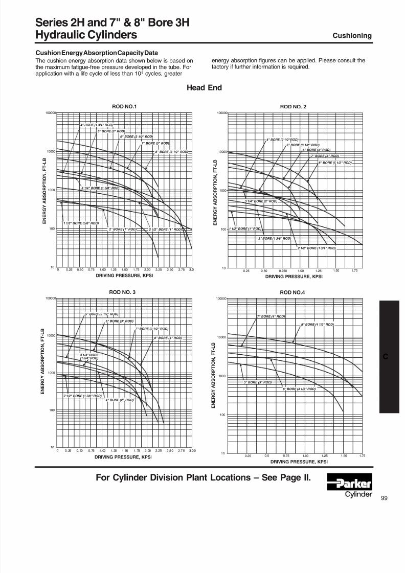
8/7/2019 Hydraulic Fundamental
http://slidepdf.com/reader/full/hydraulic-fundamental 21/52
For Cylinder Division Plant Locations – See Page II.
Cushioning
Cushion Energy Absorption Capacity DataThe cushion energy absorption data shown below is based onthe maximum fatigue-free pressure developed in the tube. Forapplication with a life cycle of less than 106 cycles, greater
energy absorption figures can be applied. Please consult thefactory if further information is required.
Head End
ROD NO.1
10
100
1000
10000
100000
DRIVING PRESSURE, KPSI
E N E R G Y A B S
O R P T I O N ,
F T - L B
0 0.25 0.50 0.75 1.00 1.25 1.50 1.75 2.00 2.25 2.50 2.75 3.0
4" BORE (1 3/4" ROD)
5" BORE (2" ROD)
6" BORE (2 1/2" ROD)
8" BORE (3 1/2" ROD)
7" BORE (3" ROD)
3 1/4" BORE (1 3/8" ROD)
1 1/2" BORE (5/8" ROD)
2" BORE (1" ROD) 2 1/2" BORE (1" ROD)
ROD NO. 2
10
100
1000
10000
100000
DRIVING PRESSURE, KPSI
E N E R G Y A B S O R P T I O N , F T - L B
0.25 0.50 0.750 1.00 1.25 1.751.50
4" BORE (2 1/2"ROD)
5" BORE (3 1/2" ROD)
6" BORE (4" ROD)
7" BORE (5" ROD)
8" BORE (5 1/2" ROD)
2 1/2" BORE (1 3/4" ROD)
2" BORE (1 3/8" ROD)
1 1/2" BORE (1" ROD)
3 1/4" BORE (2" ROD)
ROD NO. 3
10
100
1000
10000
100000
DRIVING PRESSURE, KPSI
E
N E R G Y A B S O R P T I O N , F T - L B
0. 25 0. 50 0. 75 1. 00 1. 25 1. 50 1. 75 2. 00 2.25 2 .5 0 2 .7 5 3 .0 00
5" BORE (2 1/2" ROD)
6" BORE (3" ROD)
7" BORE (3 1/2" ROD)
8" BORE (4" ROD)
4" BORE (2")ROD)
2 1/2" BORE (1 3/8" ROD)
3 1/4" BORE (1 3/4" ROD)
ROD NO.4
10
100
1000
10000
100000
DRIVING PRESSURE, KPSI
E N E R G Y A B S O R P T I O N , F T - L B
0.25 0.5 0.75 1.00 1.25 1.50 1.75
7" BORE (4" ROD)
8" BORE (4 1/2" ROD)
6" BORE (3 1/2" ROD)
5" BORE (3" ROD)
Series 2H and 7" & 8" Bore 3HHydraulic Cylinders
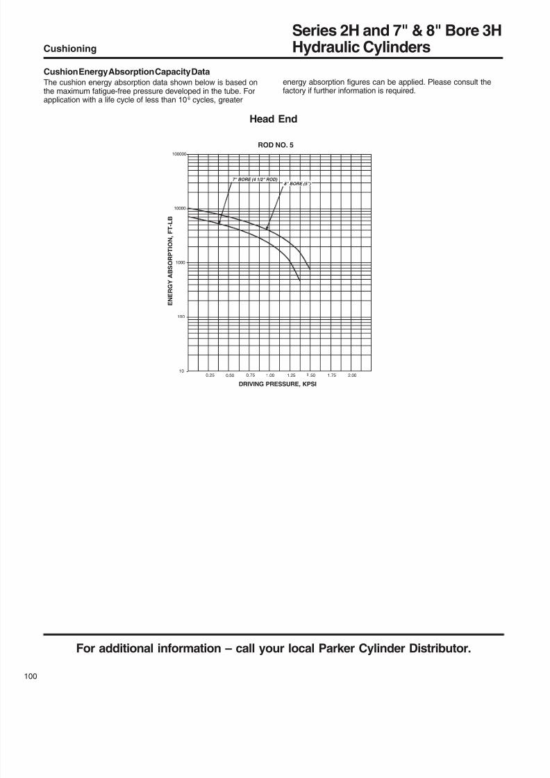
8/7/2019 Hydraulic Fundamental
http://slidepdf.com/reader/full/hydraulic-fundamental 22/52
For additional information – call your local Parker Cylinder Distributor.
00
Cushioning
Cushion Energy Absorption Capacity DataThe cushion energy absorption data shown below is based onthe maximum fatigue-free pressure developed in the tube. Forapplication with a life cycle of less than 106 cycles, greater
energy absorption figures can be applied. Please consult thefactory if further information is required.
Head End
ROD NO. 5
10
100
1000
10000
100000
DRIVING PRESSURE, KPSI
E N E R G Y A B S O R P T I O N , F T - L B
0.25 0.50 0.75 1.00 1.25 .50 1.75 2.00
7" BORE (4 1/2" ROD) 8" BORE (5")
Series 2H and 7" & 8" Bore 3HHydraulic Cylinders
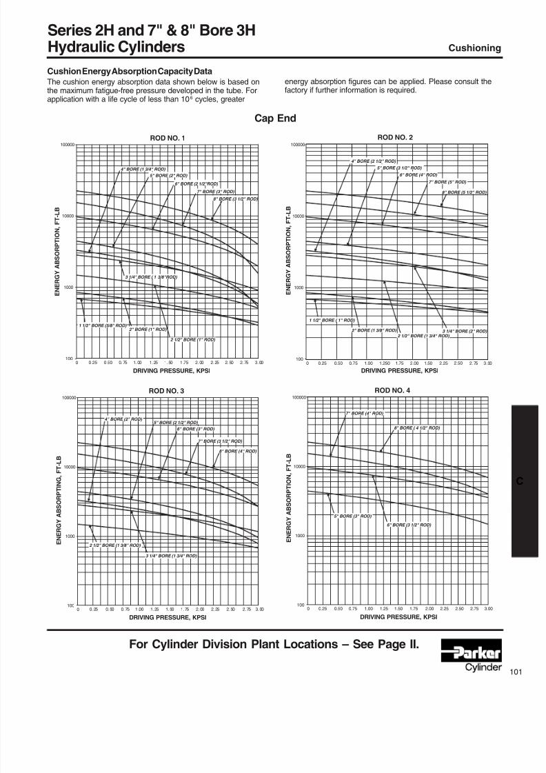
8/7/2019 Hydraulic Fundamental
http://slidepdf.com/reader/full/hydraulic-fundamental 23/52
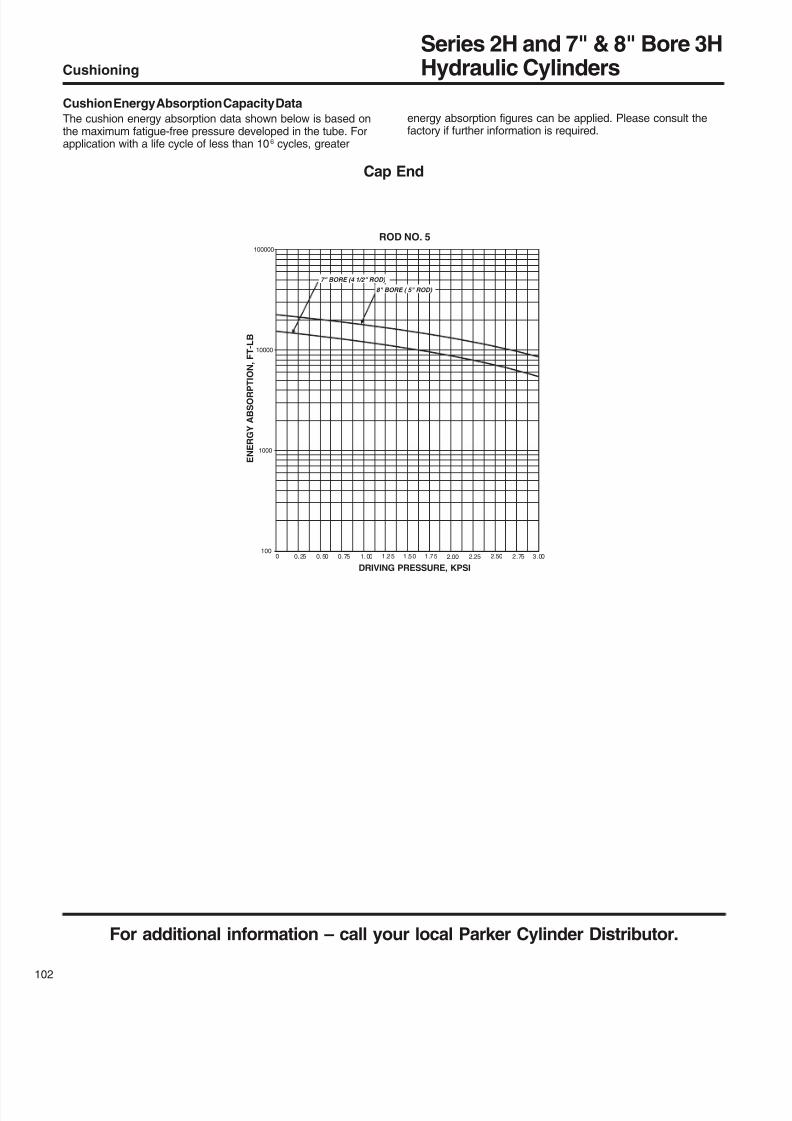
8/7/2019 Hydraulic Fundamental
http://slidepdf.com/reader/full/hydraulic-fundamental 24/52
For additional information – call your local Parker Cylinder Distributor.
02
Cushioning
Cushion Energy Absorption Capacity DataThe cushion energy absorption data shown below is based onthe maximum fatigue-free pressure developed in the tube. Forapplication with a life cycle of less than 106 cycles, greater
energy absorption figures can be applied. Please consult thefactory if further information is required.
Cap End
ROD NO. 5
100
1000
10000
100000
DRIVING PRESSURE, KPSI
E N E R G Y A B S O R P T
I O N , F T - L B
0 0. 25 0. 50 0. 75 1. 00 1 .2 5 1 .5 0 1 .7 5 2.00 2.25 2.50 2.75 3.00
7" BORE (4 1/2" ROD)
8" BORE ( 5" ROD)
Series 2H and 7" & 8" Bore 3HHydraulic Cylinders

8/7/2019 Hydraulic Fundamental
http://slidepdf.com/reader/full/hydraulic-fundamental 25/52
For Cylinder Division Plant Locations – See Page II.
NOTES
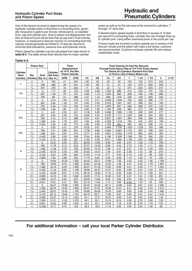
8/7/2019 Hydraulic Fundamental
http://slidepdf.com/reader/full/hydraulic-fundamental 26/52
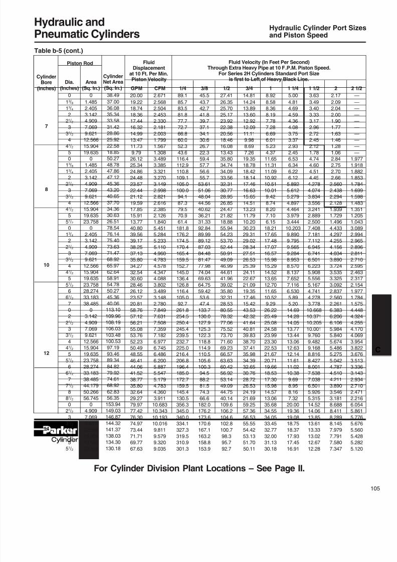
8/7/2019 Hydraulic Fundamental
http://slidepdf.com/reader/full/hydraulic-fundamental 27/52
Hydraulic andPneumatic Cylinders
For Cylinder Division Plant Locations – See Page II.
3/8
45.543.7
42.7
41.8
39.7
37.1
34.1
30.6
26.7
22.3
59.4
57.7
56.6
55.7
53.61
51.0648.04
44.56
40.62
36.21
31.33
92.84
89.99
89.12
87.03
84.48
81.47
77.98
74.04
69.63
64.75
59.42
53.6
47.4
133.7
130.0
127.9
125.3
122.3
118.8
114.9
110.5
105.6
100.3
94.5
88.2
81.574.3
66.6
182.0
176.2
173.6
170.6
167.1
163.2
158.8
153.9
2
2.172.09
2.04
2.00
1.90
1.77
1.63
1.46
1.28
1.06
2.84
2.75
2.70
2.66
2.560
2.4382.294
2.128
1.939
1.729
1.496
4.433
4.297
4.255
4.156
4.034
3.890
3.724
3.535
3.325
3.092
2.837
2.560
2.261
6.383
6.206
6.106
5.984
5.840
5.674
5.486
5.275
5.042
4.787
4.510
4.211
3.8903.546
3.181
8.688
8.411
8.289
8.145
7.979
7.791
7.580
7.347
3/4
14.8114.24
13.89
13.60
12.92
12.09
11.11
9.98
8.69
7.26
19.35
18.78
18.42
18.14
17.46
16.6315.65
14.51
13.23
11.79
10.20
30.23
29.31
29.02
28.34
27.51
26.53
25.39
24.11
22.67
21.09
19.35
17.46
15.42
43.53
42.32
41.64
40.81
39.83
38.70
37.41
35.98
34.39
32.65
30.76
28.72
26.5324.19
21.69
59.25
57.36
56.53
55.55
54.42
53.13
51.70
50.11
1
8.928.58
8.36
8.19
7.78
7.28
6.69
6.01
5.23
4.37
11.65
11.31
11.09
10.92
10.51
10.019.42
8.74
8.20
7.10
6.15
18.21
17.65
17.48
17.07
16.57
15.98
15.29
14.52
13.65
12.70
11.65
10.52
9.29
26.22
25.49
25.08
24.58
23.99
23.30
22.53
21.67
20.71
19.66
18.53
17.30
15.9814.57
13.06
35.68
34.55
34.05
33.45
32.77
32.00
31.13
30.18
1 1/4
5.004.81
4.69
4.59
4.36
4.08
3.75
3.37
2.93
2.45
6.53
6.34
6.22
6.12
5.892
5.6125.279
4.897
4.464
3.979
3.444
10.203
9.890
9.795
9.565
9.284
8.953
8.570
8.137
7.652
7.116
6.530
5.89
5.20
14.69
14.28
14.05
13.77
13.44
13.06
12.63
12.14
11.61
11.02
10.38
9.69
8.958.16
7.32
20.00
19.36
19.08
18.75
18.37
17.93
17.45
16.91
1 1/2
3.633.49
3.40
3.33
3.17
2.96
2.72
2.45
2.12
1.78
4.74
4.60
4.51
4.45
4.278
4.0743.834
3.556
3.241
2.889
2.500
7.408
7.181
7.112
6.945
6.741
6.501
6.223
5.908
5.556
5.167
4.741
4.278
3.778
10.668
10.371
10.205
10.001
9.760
9.482
9.168
8.816
8.427
8.001
7.538
7.038
6.5015.926
5.315
14.52
14.06
13.85
13.61
13.33
13.02
12.67
12.28
2 1/2
——
—
—
—
—
—
—
—
—
1.977
1.918
1.882
1.853
1.784
1.6991.598
1.483
1.351
1.205
1.043
3.089
2.994
2.965
2.896
2.811
2.710
2.595
2.463
2.317
2.154
1.977
1.784
1.575
4.448
4.324
4.255
4.170
4.069
3.954
3.822
3.676
3.513
3.336
3.143
2.934
2.7102.471
2.216
6.054
5.861
5.776
5.676
5.560
5.428
5.282
5.120
1/2
27.4126.35
25.70
25.17
23.92
22.38
20.56
18.46
16.08
13.43
35.80
34.74
34.09
33.56
32.31
30.7728.95
26.85
24.47
21.82
18.88
55.94
54.23
53.70
52.44
50.91
49.09
46.99
44.61
41.96
39.02
35.80
32.31
28.53
80.55
78.32
77.06
75.52
73.70
71.60
69.23
66.57
63.63
60.42
56.92
53.14
49.0944.75
40.14
109.6
106.2
104.6
102.8
100.7
98.3
95.7
92.7
Hydraulic Cylinder Port Sizesand Piston Speed
Area(Sq. In.)
01.485
2.405
3.142
4.909
7.069
9.621
12.566
15.904
19.635
0
1.485
2.405
3.142
4.909
7.0699.621
12.566
15.904
19.635
23.758
0
2.405
3.142
4.909
7.069
9.621
12.566
15.904
19.635
23.758
28.274
33.183
38.485
0
3.142
4.909
7.069
9.621
12.566
15.904
19.635
23.758
28.274
33.183
38.485
44.17950.266
56.745
0
4.909
7.069
9.621
12.566
15.904
19.635
23.758
CylinderBore
(Inches)
7
8
10
12
14
Dia.(Inches)
013 / 813 / 42
21 / 23
31 / 24
41 / 25
0
13 / 813 / 42
21 / 2
331 / 24
41 / 25
51 / 20
13 / 42
21 / 23
31 / 24
41 / 25
51 / 26
61 / 27
0
2
21 / 23
31 / 24
41 / 25
51 / 26
61 / 27
71 / 28
81 / 20
21 / 23
31 / 24
41 / 25
51 / 2
CylinderNet Area(Sq. In.)
38.4937.00
36.08
35.34
33.58
31.42
28.86
25.92
22.58
18.85
50.27
48.78
47.86
47.12
45.36
43.2040.65
37.70
34.36
30.63
26.51
78.54
76.14
75.40
73.63
71.47
68.92
65.97
62.64
58.91
54.78
50.27
45.36
40.06
113.10
109.96
108.19
106.03
103.48
100.53
97.19
93.46
89.34
84.82
79.92
74.61
68.9262.83
56.35
153.94
149.03
146.87
144.32
141.37
138.03
134.30
130.18
GPM
20.0019.22
18.74
18.36
17.44
16.32
14.99
13.47
11.73
9.79
26.12
25.34
24.86
24.48
23.57
22.4421.12
19.59
17.85
15.91
13.77
40.80
39.56
39.17
38.25
37.13
35.80
34.27
32.54
30.60
28.46
26.12
23.57
20.81
58.76
57.12
56.21
55.08
53.76
52.23
50.49
48.55
46.41
44.06
41.52
38.77
35.8032.64
29.27
79.97
77.42
76.30
74.97
73.44
71.71
69.77
67.63
CFM
2.6712.568
2.504
2.453
2.330
2.181
2.003
1.799
1.567
1.308
3.489
3.385
3.321
3.270
3.149
2.9982.821
2.616
2.385
2.126
1.840
5.451
5.284
5.233
5.110
4.960
4.783
4.578
4.347
4.088
3.802
3.489
3.148
2.780
7.849
7.631
7.508
7.359
7.182
6.977
6.745
6.486
6.200
5.887
5.547
5.179
4.7834.360
3.911
10.683
10.343
10.193
10.016
9.811
9.579
9.320
9.035
1/4
89.185.7
83.5
81.8
77.7
72.7
66.8
60.0
52.3
43.6
116.4
112.9
110.8
109.1
105.0
100.094.1
87.3
79.5
70.9
61.4
181.8
176.2
174.5
170.4
165.4
159.5
152.7
145.0
136.4
126.8
116.4
105.0
92.7
261.8
254.5
250.4
245.4
239.5
232.7
225.0
216.4
206.8
196.4
185.0
172.7
159.5145.4
130.5
356.3
345.0
340.0
334.1
327.3
319.5
310.9
301.3
FluidDisplacement
at 10 Ft. Per Min.Piston Velocity
Piston Rod Fluid Velocity (In Feet Per Second)Through Extra Heavy Pipe at 10 F.P.M. Piston Speed.
For Series 2H Cylinders Standard Port Sizeis first to Left of Heavy Black Line.
Table b-5 (cont.)
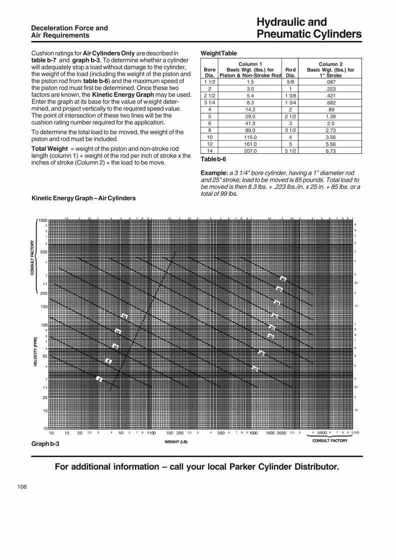
8/7/2019 Hydraulic Fundamental
http://slidepdf.com/reader/full/hydraulic-fundamental 28/52
Hydraulic andPneumatic Cylinders
For additional information – call your local Parker Cylinder Distributor.
06
10
1015 20 2 5 3 4 50 6 7 8 9100 150 200 2 5 3 4 500 6 7 8 9 1000 1500 2000 2 5 3 4 5000 6 7 8 9 10 ,0 00
15
20
2.5
3
4
50
6
7
8
9
100
150
200
2.5
3
4
500
6
7
8
9
1000
2
6
1 0
1 4
1 8
2 2
2 6
3 0
3 3
3 6
3 9
4 2
4 5
WEIGHT (LB)
V E L O C I T Y ( F P M )
C O N S U L T F A C T O R Y
15 2 25 3 4 5 6 7 8 9 1 15 2 25 3 4 5 6 7 8 9 1 15 2 25 3 4 5 6 7 8 9 1
15
2
25
3
4
5
6
7
8
9
1
15
2
25
3
4
5
6
7
8
9
CONSULT FACTORY
Column 1Basic Wgt. (lbs.) for
Piston & Non-Stroke Rod
1.5
3.0
5.48.3
14.2
29.0
41.0
89.0
115.0
161.0
207.0
Table b-6
Example: a 3 1/4" bore cylinder, having a 1" diameter rod and 25" stroke; load to be moved is 85 pounds. Total load to be moved is then 8.3 lbs. + .223 lbs./in. x 25 in. + 85 lbs. or a
total of 99 lbs.
Column 2Basic Wgt. (lbs.) for
1" Stroke
.087
.223
.421
.682
.89
1.39
2.0
2.73
3.56
5.56
6.73
RodDia.
5/8
1
1 3/81 3/4
2
2 1/2
3
3 1/2
4
5
5 1/2
Deceleration Force andAir Requirements
Cushion ratings for Air Cylinders Only are described intable b-7 and graph b-3. To determine whether a cylinderwill adequately stop a load without damage to the cylinder,the weight of the load (including the weight of the piston andthe piston rod from table b-6) and the maximum speed ofthe piston rod must first be determined. Once these two
factors are known, the Kinetic Energy Graph may be used.Enter the graph at its base for the value of weight deter-mined, and project vertically to the required speed value.The point of intersection of these two lines will be thecushion rating number required for the application.
To determine the total load to be moved, the weight of thepiston and rod must be included.
Total Weight = weight of the piston and non-stroke rodlength (column 1) + weight of the rod per inch of stroke x theinches of stroke (Column 2) + the load to be move.
Weight Table
Kinetic Energy Graph – Air Cylinders
Graph b-3
BoreDia.
1 1/2
2
2 1/23 1/4
4
5
6
8
10
12
14
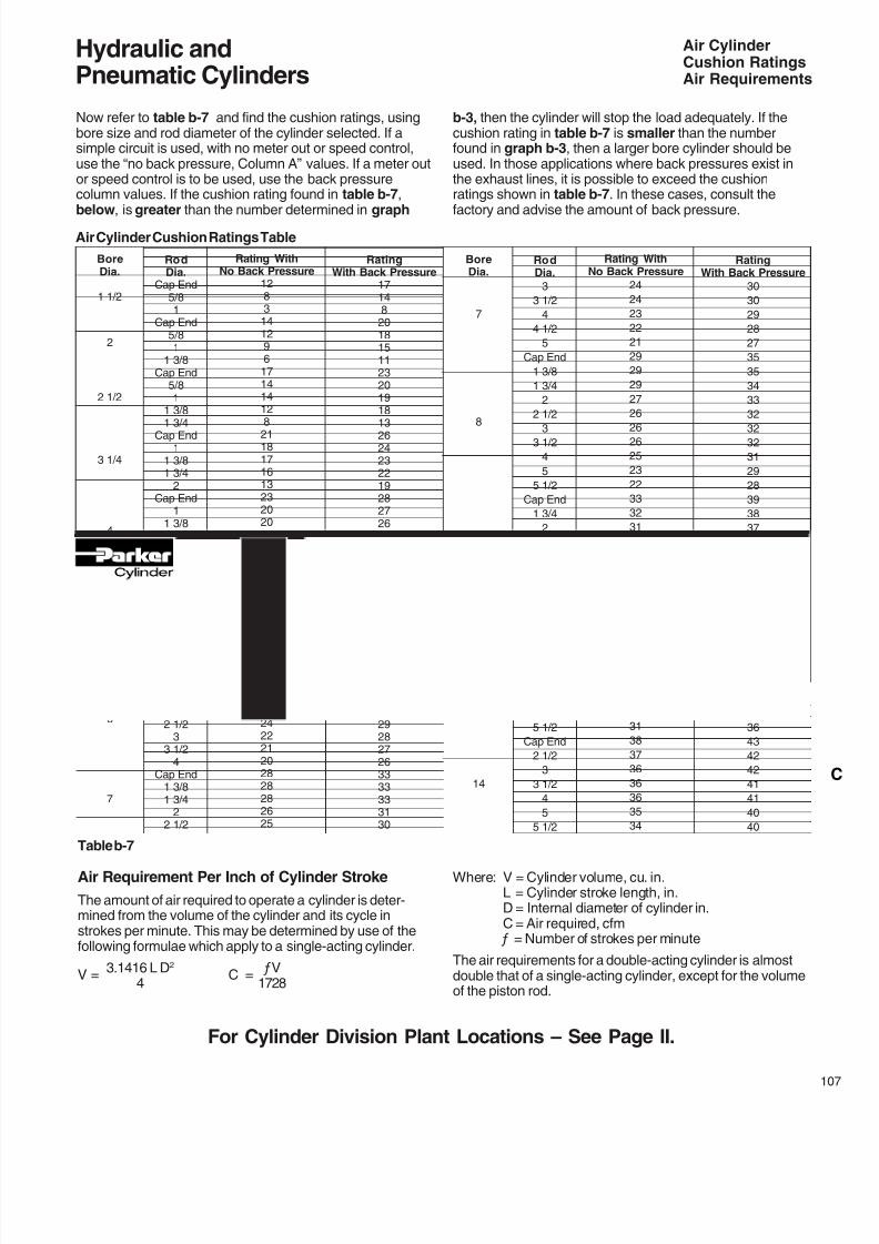
8/7/2019 Hydraulic Fundamental
http://slidepdf.com/reader/full/hydraulic-fundamental 29/52
Hydraulic andPneumatic Cylinders
For Cylinder Division Plant Locations – See Page II.
Now refer to table b-7 and find the cushion ratings, usingbore size and rod diameter of the cylinder selected. If asimple circuit is used, with no meter out or speed control,use the “no back pressure, Column A” values. If a meter outor speed control is to be used, use the back pressurecolumn values. If the cushion rating found in table b-7,
below, is greater than the number determined in graph
Air CylinderCushion RatingsAir Requirements
Air Cylinder Cushion Ratings Table
RodDia.
Cap End5/81
Cap End5/81
1 3/8Cap End
5/81
1 3/8
1 3/4Cap End1
1 3/81 3/4
2Cap End
11 3/81 3/4
22 1/2
Cap End1
1 3/81 3/4
2
2 1/233 1/2
Cap End1 3/81 3/4
22 1/2
33 1/2
4Cap End
1 3/81 3/4
22 1/2
BoreDia.
1 1/2
2
2 1/2
3 1/4
4
5
6
7
RatingWith Back Pressure
17148
2018151123201918
1326242322192827262523223128282826
25242031313129292827263333333130
Rating WithNo Back Pressure
128314129617141412
821181716132320201917172623232220
19181526262624242221202828282625
RodDia.
3
3 1/2
4
4 1/2
5
Cap End
1 3/8
1 3/4
2
2 1/2
33 1/2
4
5
5 1/2
Cap End
1 3/4
2
2 1/2
3
3 1/2
4
5
5 1/2
Cap End
22 1/2
3
3 1/2
4
5
5 1/2
Cap End
2 1/2
3
3 1/2
4
5
5 1/2
BoreDia.
7
8
10
12
14
RatingWith Back Pressure
30
30
29
28
27
35
35
34
33
32
3232
31
29
28
39
38
37
36
36
36
36
34
33
41
3938
38
38
38
36
36
43
42
42
41
41
40
40
Rating WithNo Back Pressure
24
24
23
22
21
29
29
29
27
26
2626
25
23
22
33
32
31
31
30
30
30
28
27
35
3333
33
32
32
31
31
38
37
36
36
36
35
34
Table b-7
Air Requirement Per Inch of Cylinder Stroke
The amount of air required to operate a cylinder is deter-mined from the volume of the cylinder and its cycle instrokes per minute. This may be determined by use of thefollowing formulae which apply to a single-acting cylinder.
V =3.1416 L D2
C = ƒV
4 1728
Where: V = Cylinder volume, cu. in.L = Cylinder stroke length, in.D = Internal diameter of cylinder in.C = Air required, cfm
ƒ = Number of strokes per minute
The air requirements for a double-acting cylinder is almostdouble that of a single-acting cylinder, except for the volumeof the piston rod.
b-3, then the cylinder will stop the load adequately. If thecushion rating in table b-7 is smaller than the numberfound in graph b-3, then a larger bore cylinder should beused. In those applications where back pressures exist inthe exhaust lines, it is possible to exceed the cushionratings shown in table b-7. In these cases, consult the
factory and advise the amount of back pressure.
8/7/2019 Hydraulic Fundamental
http://slidepdf.com/reader/full/hydraulic-fundamental 30/52
Hydraulic andPneumatic Cylinders
For additional information – call your local Parker Cylinder Distributor.
08
Air Requirements
The air flow requirements of a cylinder in terms of cfmshould not be confused with compressor ratings which aregiven in terms of free air. If compressor capacity is involvedin the consideration of cylinder air requirements it will benecessary to convert cfm values to free air values. Thisrelationship varies for different gauge pressures.
Thrust (pounds) = operating pressure x area of cylinderbore.
Note: That on the “out” stroke the air pressure is working on the entire piston area but on the “in” stroke the air pressure works on the piston area less the rod area.
Graph b-4 and b-5 offer a simple means to select pneu-matic components for dynamic cylinder applications. It isonly necessary to know the force required, the desiredspeed and the pressure which can be maintained at the
inlet to the F-R-L “Combo.” The graphs assume averageconditions relative to air line sizes, system layout, friction,etc. At higher speeds, consider appropriate cushioning ofcylinders.
The general procedure to follow when using these graphs is:
1. Select the appropriate graph depending upon the pres-sure which can be maintained to the system – graph b-4for 100 psig and graph b-5 for 80 psig.
2. Determine appropriate cylinder bore. Values underneaththe diagonal cylinder bore lines indicate the maximumrecommended dynamic thrust developed while the cylinderis in motion. The data in the table at the bottom of eachgraph indicates available static force applications in whichclamping force is a prime consideration in determing cylinderbore.
Table b-8Thrust Developed
T H I S G R A P H I S D E T E R M I N E D B Y H A V I N G
1 0 0 P S I G A V A I L A B L E U N D E R F L O W I N G C O N D I T I O N S .
1 0 0
1 0
1 5
2 0
3 0
4 0
5 0
6 0
7 0
8 0
9 0
1 5 0
2 0 0
3 0 0
4 0 0
5 0 0
6 0 0
7 0 0
8 0 0
9 0 0
1 0 0 0
–14
–12
–10
–8
–6
–4
–3
–2
–0.5
–1
1 0 " B O R E
3 9 2 0
L B S .
8 " B O R E
2 5 0 0
L B S .
6 " B O R E
1 4 0 0
L B S .
5 " B O R E
9 8 0 L B
S .
4 " B O R E
6 2 0 L B
S .
3 1 / 4 " B O R E
4 1 0 L B
S .
2 1 / 2 " B O R E
2 4 0 L B
S .
2 " B O R E
1 5 5 L B
S .
1 1 / 2 " B O R E
8 8 L B S
.
ROD SPEED fpm
C V F O R I N D I V
I D U A L V A L V E & S P E E D C O N T R O L S
graph b-4
BORE SIZE 1 1/2" 2" 2 1/2" 3 1/4" 4" 5" 6" 8" 10"
DYNAMIC THRUST (lbs.) 88 155 240 410 620 980 1400 500 3920
STATIC THRUST (lbs.) 177 314 491 830 1250 1960 2820 5020 7850
8/7/2019 Hydraulic Fundamental
http://slidepdf.com/reader/full/hydraulic-fundamental 31/52
Hydraulic andPneumatic Cylinders
For Cylinder Division Plant Locations – See Page II.
3. Read upward on appropriate rod speed line to intersec-tion with diagonal cylinder bore line. Read right fromintersection point to determine the required Cv of the valveand the speed controls. Both the valve and speed controlsmust have this Cv.
The following examples illustrate use of the graphs:
Example 1: Assume it is necessary to raise a 900-pound load 24 inches in two seconds. With 100 psig maintained at the inlet to the F-R-L, use graph b-4. The 5-inch bore cylinder is capable of developing the required thrust while in motion. Since 24 inches in two seconds is equal to 60 fpm,read upward on the 60 fpm line to the intersection of the 5- inch bore diagonal line. Reading to the right indicates that the required valve and speed controls must each have a C v
of over 1.9.
Air Requirements
Example 2: Assume similar conditions to Example 1 except that only 80- psig will be available under flowing conditions.Using graph b-5, a 6-inch bore cylinder is indicated. Read upward on the 60 fpm line to the intersection point. Interpo- lation of the right-hand scale indicates a required valve and speed control C v of over 2.8.
Example 3: Assume similar conditions to Example 1 except that the load is being moved in a horizontal plane with a coefficient of sliding friction of 0.2. Only a 180-pound thrust is now required (900 lb. x 0.2). Consult graph b-4. The 2 1/2 inch bore cylinder will develop sufficient thrust, and at 60 fpm requires a valve and speed control C v of about 0.5.
Table b-9Thrust Developed
T H I S G R A P H I S D E T E R M I N E D B Y H A V I N G
8 0 P S I G A V A I L A B L E U N D E R F L O W I N G C O N D I T I O N S .
1 0
0
1
0
1
5
2
0
3
0
4
0
5
0
6
0
7
0
8
0
9
0
1 5
0
2 0
0
3 0
0
4 0
0
5 0
0
6 0
0
7 0
0
8 0
0
9 0
0
1 0 0
0
–14
–12
–10
–8
–6
–4
–3
–2
–0.6
–1
1 0 " B O R E
2 5 0 0
L B S .
8 " B O R E
1 6 0 0
L B S .
6 " B O R E
9 0 0 L B
S .
5 " B O R E
6 3 0 L B
S .
4 " B O R E
4 0 0 L B
S .
3 1 / 4 " B O R E
2 6 0 L B
S .
2 1 / 2 " B O R E
1 6 0 L B
S .
1 1 / 2 " B O R E
6 0 L B S .
ROD SPEED fpm
C V F O R I N D I V
I D U A L V A L V E & S P E E D C O N T R O L S
2 " B O R E
1 0 0 L B
S .
BORE SIZE 1 1/2 2 2 1/2 3 1/4 4 5 6 8 10
DYNAMIC THRUST (lbs.) 60 100 160 260 400 630 900 1600 2500
STATIC THRUST (lbs.) 141 251 393 663 1000 1570 2260 4010 6280
graph b-5
8/7/2019 Hydraulic Fundamental
http://slidepdf.com/reader/full/hydraulic-fundamental 32/52
Hydraulic andPneumatic Cylinders
For additional information – call your local Parker Cylinder Distributor.
10
.10
7
5
Todetermineextralengthofpistonrodrequiredtoaccommodateboot,calculate
BL=StrokexLF+11 / 8"
BL+Std.LA=lengthofpistonrodtoextendbeyondtheretainer.
NOTE:CheckallBootO.D’sagainststd.“E”dimensionfromcatalog.Thismaybecriticalonfootmountedcylinders.
Tandem Cylinders
Atandemcylinderismadeupoftwocylindersmountedinlinewithpistonsconnectedbyacommonpistonrodandrodsealsinstalledbetweenthecylinderstopermitdoubleactingoperationofeach.Tandemcylindersallowincreasedoutputforcewhenmountingwidthorheightarerestricted.
Modifcations Special AssembliesTandem Cylinders
Modifcations: The following modications can besupplied on most Parker cylinders. For specic availabilitysee modication chart on page 3.
Metallic Rod Wiper
When specied metallic rod wipers can be supplied instead
ofthestandardsyntheticrubberwiperseal.Recommendedinapplicationswherecontaminantstendtoclingtotheextendedpistonrodandwoulddamagethesyntheticrubberwiperseal.Installationofmetallicrodwiperdoesnotaect cylinder dimensions. It is available at extra cost.
Gland Drain – Series2H.Forothercylinders,consultfactory.
Hydraulic uids tend to adhere to the piston rods, during theextend stroke, and an accumulation of uid can collect in thecavity behind the gland wiperseal on long stroke cylinders.
A1 / 8" N.P.T.F. gland drain port can be provided in the glandretainer.Apassageintheglandbetweenthewipersealand lipseal is provided to drain o any accumulation of uid
betweentheseals.Seedrawingbelow.Itisrecommendedthattheglanddrainportbepipedbackto the uid reservoir and that the reservoir be located belowthe level of the head of the cylinder.
On11 / 2"boresizeSeries2Hcyls.,thedrainportislocatedintheheadadjacenttotheportandoncode2rod,theretainerthicknessincreasesto5 / 8".On2"thru8"boresizesthedrainportislocatedin
theretainerasshown.Air Bleeds
Inmosthydrauliccircuits,cylindersareconsideredself-bleedingwhencycledfullstroke.Ifairbleedsarerequiredand specied, 1 / 8" NPTF Air Bleed Ports for venting air canbe provided at both ends of the cylinder body, or on theheadorcap.Toorder,specify”BleedPort”,andindicatepositiondesired.
Air Bleed Port
Rod End Boots
Cylinders have a hardened bearing surface on the pistonrodtoresistexternaldamage,andareequippedwiththehigh eciency “Wiperseal” to remove external dust anddirt.Exposedpistonrodsthataresubjectedtocontami-nantswithairhardeningproperties,suchaspaint,should
beprotected.Insuchapplications,theuseofacollapsingcover should be considered. This is commonly referredtoasa“boot”.Calculatethelongerrodendrequiredtoaccommodatethecollapsedlengthofthebootfromthefollowingdata.
Duplex Cylinders
Aduplexcylinderismadeupoftwocylindersmountedinlinewithpistonsnotconnectedandwithrodsealsinstalledbetweenthecylinderstopermitdoubleactingoperationofeach.Cylindersmaybemountedwithpistonrodtopiston(asshown)orbacktobackandaregenerallyusedtoprovide three position operation.
LF
OD
RD
.13
21/4
1/2
.13
21/4
5/8
.13
25/8
1
.13
3
1 3/8
.13
3 3/8
1 3/4
.13
3 3/4
2
.10
51/8
3
.10
55/8
3 1/2
.10
61/4
4
.10
71/2
51/2
1/2 5/8
RD
BL
OD
MM
MM
MMMM
.13
4 3/8
21/2
Reducedoperatingpressureisrequiredforthisconstruction.Contactfactory.
Reducedoperatingpressureisrequiredforthisconstruction.Contactfactory.
8/7/2019 Hydraulic Fundamental
http://slidepdf.com/reader/full/hydraulic-fundamental 33/52
Hydraulic andPneumatic Cylinders
For Cylinder Division Plant Locations – See Page II.
Rod Dia.
5/8"
1"
1 3/8"
1 3/4"
Piston Rod Wt. Per Inch
.89
1.40
2.00
2.72
BB, C, CB, D, DB
DD, E, G, HH, JJ9.09.3
13.217.119.525.541.046.053.058.082.086.0
133.0140.0242.0253.0
276.0309.0
The weights shown in Tables A and B are for Parker Series 2H, 3H (7” & 8”), HD, VH, 3L,2A, 2AN and MA cylinders with various piston rod diameters. To determine the net weightof a cylinder, first select the proper basic weight for zero stroke, then calculate the weightof the cylinder stroke and add the result to the basic weight. For extra rod extension use
Cylinder Weights
piston rod weights per inch shown in Table C. Weights of cylinders with intermediate rodsmay be estimated from table below by taking the difference between the piston rodweights per inch and adding it to the Code 1 weight for the cylinder bore size involved. Todetermine the net weight of Series VH cylinders, use data in Table A and multiply by 1.10.
Bore
Size
1 1/2"
2"
2 1/2"
3 1/4"
4"
5"
6"
7"
8"
Rod
Dia.5/8"1"1"
1 3/8"1"
1 3/4"1 3/8"
2"1 3/4"2 1/2"
2"3 1/2"2 1/2"
4"3"5"
3 1/2"5 1/2"
Rod
Code1212121212121212
12
F, H, HB, J, JB
T, TB, TC, TD7.88.411.613.517.022.532.037.048.052.076.088.0
125.0133.0233.0240.0
262.0300.0
Add Per Inch
of Stroke.5.6.8
1.01.11.51.82.22.53.23.45.25.27.36.710.3
9.013.0
KF, KJ KJB
KT, KTB, KTD9.79.114.619.421.027.043.048.059.092.096.0
117.0153.0182.0320.0341.0
323.0390.0
KC, KCB, KD
KDD, KE, KJJ10.810.716.820.624.530.052.057.063.097.0
102.0123.0159.0190.0339.0360.0
331.0411.0
Add Per Inch
of Stroke.6.81.01.41.32.22.23.13.24.64.87.96.6
10.98.7
15.9
11.719.7
Single Rod CylindersBasic Wt. Zero Stroke
Double Rod CylindersBasic Wt. Zero Stroke
Table A Cylinder Weights, in pounds, for Series 2H, 3H (7" & 8"), HD and VH hydraulic cylinders
BB, C, CB, D, DBDD, E, HB, JB
2.93.04.35.16.97.58.99.710.013.617.518.028.031.031.542.046.046.566.077.0
102.085.087.099.0
172.0188.0264.0282.0358.0448.0519.0
BoreSize
1"
1 1/2"
2"
2 1/2"
3 1/4"
4"
5"
6"
7"
8"
10"
12"
14"
RodDia.1/2"5/8"5/8"1"
5/8"1"
1 3/8"5/8"1"
1 3/4"1"
1 3/8"2"1"
1 3/8"2 1/2"
1"1 3/8"3 1/2"1 3/8"
4"1 3/8"
2"1 3/8"5 1/2"1 3/4"5 1/2"
2"5 1/2"2 1/2"5 1/2"
T, TB, TC,TD, F, H, J
2.52.63.74.56.57.08.59.09.513.216.517.027.026.026.536.039.039.563.068.0
100.080.082.094.0
168.0182.0258.0274.0350.0435.0510.0
SeriesMA––
.25
.35.4.5–.5.6–
.65.8–.81.0–.91.1–––––––––––––
KF, KJ KTKTB, KTD
4.74.94.25.88.29.0
11.211.412.019.822.022.543.033.033.553.048.048.596.080.0144.092.096.0108.0256.0178.0330.0270.0420.0440.0490.0
Single Rod CylindersBasic Wt. Zero Stroke
Double Rod CylindersBasic Wt. Zero Stroke
Table B Cylinder Weights, in pounds, for Series 2A, 2AN, 3L and MA cylinders
Add Per Inchof Stroke
2A, 2AN,3L.20.23.3.4.5
.63.8.6
.731.1.8
1.01.41.01.22.01.11.33.61.54.52.03.52.08.02.58.53.59.54.5
10.0
SeriesMA––.5.7.8
1.0–
1.01.2–
1.31.6–
1.62.0–
1.82.2–––––––––––––
Add Per Inchof Stroke
2A, 2AN,3L.40.46.6.8
1.01.31.61.21.52.21.62.02.82.02.54.02.22.67.23.09.04.07.04.016.05.017.07.019.09.020.0
Table CRod Dia.
2"
2 1/2"
3"
3 1/2"
Rod Dia.
4"
4 1/2"
5"
5 1/2"
Piston Rod Wt. Per Inch
.09
.22
.42
.68
Piston Rod Wt. Per Inch
3.56
4.51
5.56
6.72
KC, KCB, KDKDD, KE, KJB
5.55.74.86.78.69.511.612.112.520.523.023.544.038.038.558.055.055.5103.089.0153.097.0101.0113.0261.0184.0335.0280.0430.0655.0705.0
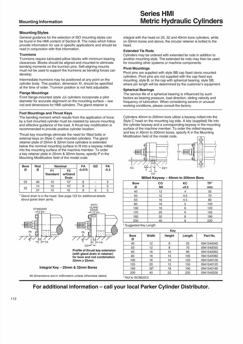
8/7/2019 Hydraulic Fundamental
http://slidepdf.com/reader/full/hydraulic-fundamental 34/52
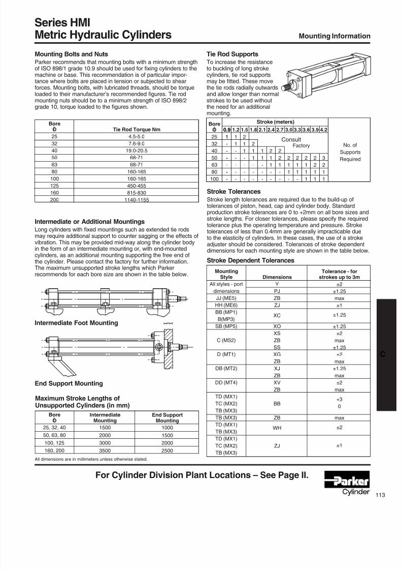
8/7/2019 Hydraulic Fundamental
http://slidepdf.com/reader/full/hydraulic-fundamental 35/52
For Cylinder Division Plant Locations – See Page II.
Tie Rod SupportsTo increase the resistanceto buckling of long strokecylinders, tie rod supportsmay be tted. These movethe tie rods radially outwardsand allow longer than normalstrokes to be used withoutthe need for an additionalmounting.
2.1
1
1
-
-
-
1.8
2
1
1
-
-
-
2.4
2
1
1
-
-
3.0
2
1
1
-
2.7
2
2
1
-
-
3.3
2
1
1
-
3.6
2
1
1
1
1.5
2
1
1
-
-
-
-
1.2
1
1
-
-
-
-
-
IntermediateMounting
1500
2000
3000
3500
Intermediate or Additional MountingsLong cylinders with xed mountings such as extended tie rodsmay require additional support to counter sagging or the eects ofvibration. This may be provided mid-way along the cylinder bodyin the form of an intermediate mounting or, with end-mountedcylinders, as an additional mounting supporting the free end ofthe cylinder. Please contact the factory for further information.The maximum unsupported stroke lengths which Parker recommends for each bore size are shown in the table below.
Series HMIMetric Hydraulic Cylinders Mounting Information
Intermediate Foot Mounting
End Support Mounting
Maximum Stroke Lengths ofUnsupported Cylinders (in mm)
Stroke TolerancesStroke length tolerances are required due to the build-up oftolerances of piston, head, cap and cylinder body. Standardproduction stroke tolerances are 0 to +2mm on all bore sizes andstroke lengths. For closer tolerances, please specify the requiredtolerance plus the operating temperature and pressure. Stroketolerances of less than 0.4mm are generally impracticable dueto the elasticity of cylinders. In these cases, the use of a strokeadjuster should be considered. Tolerances of stroke dependentdimensions for each mounting style are shown in the table below.
Stroke Dependent Tolerances
BoreO
25, 32, 40
50, 63, 80
100, 125
160, 200
End SupportMounting
1000
1500
2000
2500
Dimensions
Y
PJZB
ZJ
XC
XO
XS
ZB
SS
XG
ZB
XJ
ZB
XV
ZB
BB
ZB
WH
ZJ
MountingStyle
All styles - port
dimensionsJJ (ME5)
HH (ME6)
BB (MP1)
B(MP3)
SB (MP5)
C (MS2)
D (MT1)
DB (MT2)
DD (MT4)
TD (MX1)
TC (MX2)
TB (MX3)
TB (MX3)
TD (MX1)
TB (MX3)
TD (MX1)
TC (MX2)
TB (MX3)
Tolerance - forstrokes up to 3m
±2
±1.25max
±1
±1.25
±1.25
±2
max
±1.25
±2
max
±1.25
max
±2
max+3
0
max
±2
±1
BoreO
25
32
40
50
63
80
100
No. of
Supports
Required
0.9
1
-
-
-
-
-
-
0.9
1
-
-
-
-
-
-
3.9
2
2
1
1
4.2
3
2
1
1
Stroke (meters)
All dimensions are in millimeters unless otherwise stated.
Consult Factory
Mounting Bolts and NutsParker recommends that mounting bolts with a minimum strengthof ISO 898/1 grade 10.9 should be used for xing cylinders to themachine or base. This recommendation is of particular impor-tance where bolts are placed in tension or subjected to shearforces. Mounting bolts, with lubricated threads, should be torqueloaded to their manufacturer’s recommended gures. Tie rodmounting nuts should be to a minimum strength of ISO 898/2grade 10, torque loaded to the gures shown.
BoreO
25
32
40
50
63
80
100
125
160200
Tie Rod Torque Nm
4.5-5.0
7.6-9.0
19.0-20.5
68-71
68-71
160-165
160-165
450-455
815-8301140-1155
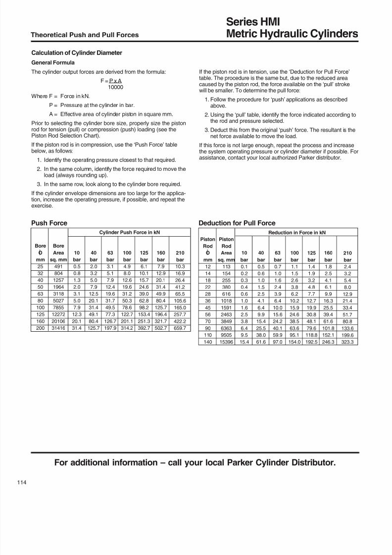
8/7/2019 Hydraulic Fundamental
http://slidepdf.com/reader/full/hydraulic-fundamental 36/52
For additional information – call your local Parker Cylinder Distributor.
14
Series HMIMetric Hydraulic CylindersTheoretical Push and Pull Forces
Calculation of Cylinder Diameter
General Formula
The cylinder output forces are derived from the formula:
F = P x A10000
Where F = Force in kN.
P = Pressure at the cylinder in bar.
A = Effective area of cylinder piston in square mm.
Prior to selecting the cylinder bore size, properly size the pistonrod for tension (pull) or compression (push) loading (see thePiston Rod Selection Chart).
If the piston rod is in compression, use the ‘Push Force’ tablebelow, as follows:
1. Identify the operating pressure closest to that required.
2. In the same column, identify the force required to move theload (always rounding up).
3. In the same row, look along to the cylinder bore required.
If the cylinder envelope dimensions are too large for the applica-tion, increase the operating pressure, if possible, and repeat theexercise.
If the piston rod is in tension, use the ‘Deduction for Pull Force’table. The procedure is the same but, due to the reduced areacaused by the piston rod, the force available on the ‘pull’ strokewill be smaller. To determine the pull force:
1. Follow the procedure for ‘push’ applications as describedabove.
2. Using the ‘pull’ table, identify the force indicated according tothe rod and pressure selected.
3. Deduct this from the original ‘push’ force. The resultant is thenet force available to move the load.
If this force is not large enough, repeat the process and increasethe system operating pressure or cylinder diameter if possible. Forassistance, contact your local authorized Parker distributor.
Push Force Deduction for Pull Force
100
bar
1.1
1.5
2.6
3.8
6.2
10.2
15.9
24.6
38.5
63.6
95.1
154.0
40
bar
0.5
0.6
1.0
1.5
2.5
4.1
6.4
9.9
15.4
25.5
38.0
61.6
160
bar
1.8
2.5
4.1
6.1
9.9
16.3
25.5
39.4
61.6
101.8
152.1
246.3
Piston
Rod
O
mm
12
14
18
22
28
36
45
56
70
90
110
140
Piston
Rod
Area
sq. mm
113
154
255
380
616
1018
1591
2463
3849
6363
9505
15396
125
bar
1.4
1.9
3.2
4.8
7.7
12.7
19.9
30.8
48.1
79.6
118.8
192.5
210
bar
2.4
3.2
5.4
8.0
12.9
21.4
33.4
51.7
80.8
133.6
199.6
323.3
63
bar
0.7
1.0
1.6
2.4
3.9
6.4
10.0
15.6
24.2
40.1
59.9
97.0
10
bar
0.1
0.2
0.3
0.4
0.6
1.0
1.6
2.5
3.8
6.4
9.5
15.4
Reduction in Force in kN
100
bar
4.9
8.0
12.6
19.6
31.2
50.3
78.6
122.7
201.1
314.2
40
bar
2.0
3.2
5.0
7.9
12.5
20.1
31.4
49.1
80.4
125.7
160
bar
7.9
12.9
20.1
31.4
49.9
80.4
125.7
196.4
321.7
502.7
Bore
O
mm
25
32
40
50
63
80
100
125
160
200
Bore
Area
sq. mm
491
804
1257
1964
3118
5027
7855
12272
20106
31416
125
bar
6.1
10.1
15.7
24.6
39.0
62.8
98.2
153.4
251.3
392.7
210
bar
10.3
16.9
26.4
41.2
65.5
105.6
165.0
257.7
422.2
659.7
63
bar
3.1
5.1
7.9
12.4
19.6
31.7
49.5
77.3
126.7
197.9
10
bar
0.5
0.8
1.3
2.0
3.1
5.0
7.9
12.3
20.1
31.4
Cylinder Push Force in kN
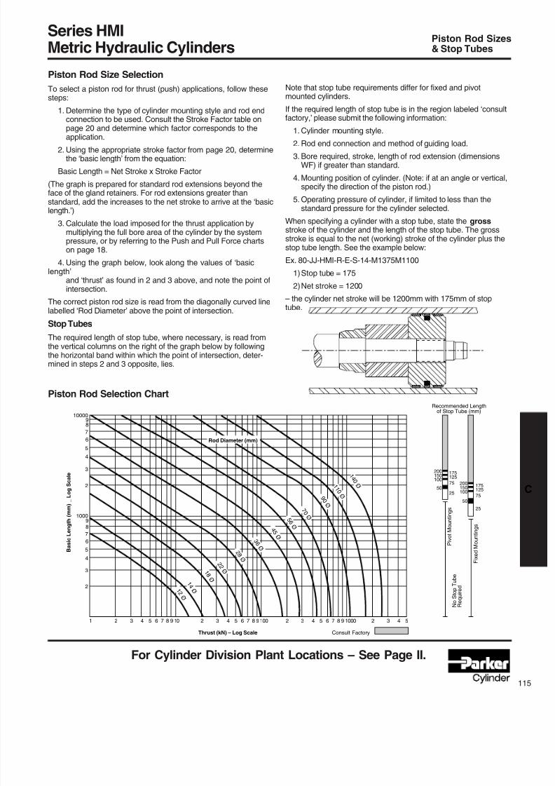
8/7/2019 Hydraulic Fundamental
http://slidepdf.com/reader/full/hydraulic-fundamental 37/52
For Cylinder Division Plant Locations – See Page II.
Piston Rod Size Selection
To select a piston rod for thrust (push) applications, follow thesesteps:
1. Determine the type of cylinder mounting style and rod endconnection to be used. Consult the Stroke Factor table onpage 20 and determine which factor corresponds to the
application.
2. Using the appropriate stroke factor from page 20, determinethe ‘basic length’ from the equation:
Basic Length = Net Stroke x Stroke Factor
(The graph is prepared for standard rod extensions beyond theface of the gland retainers. For rod extensions greater thanstandard, add the increases to the net stroke to arrive at the ‘basiclength.’)
3. Calculate the load imposed for the thrust application bymultiplying the full bore area of the cylinder by the systempressure, or by referring to the Push and Pull Force chartson page 18.
4. Using the graph below, look along the values of ‘basic
length’and ‘thrust’ as found in 2 and 3 above, and note the point ofintersection.
The correct piston rod size is read from the diagonally curved linelabelled ‘Rod Diameter’ above the point of intersection.
Stop Tubes
The required length of stop tube, where necessary, is read fromthe vertical columns on the right of the graph below by followingthe horizontal band within which the point of intersection, deter-mined in steps 2 and 3 opposite, lies.
Series HMIMetric Hydraulic Cylinders
Piston Rod Sizes& Stop Tubes
Note that stop tube requirements differ for fixed and pivotmounted cylinders.
If the required length of stop tube is in the region labeled ‘consultfactory,’ please submit the following information:
1. Cylinder mounting style.2. Rod end connection and method of guiding load.
3. Bore required, stroke, length of rod extension (dimensionsWF) if greater than standard.
4. Mounting position of cylinder. (Note: if at an angle or vertical,specify the direction of the piston rod.)
5. Operating pressure of cylinder, if limited to less than thestandard pressure for the cylinder selected.
When specifying a cylinder with a stop tube, state the grossstroke of the cylinder and the length of the stop tube. The grossstroke is equal to the net (working) stroke of the cylinder plus thestop tube length. See the example below:
Ex. 80-JJ-HMI-R-E-S-14-M1375M1100
1)Stop tube = 175
2)Net stroke = 1200
– the cylinder net stroke will be 1200mm with 175mm of stoptube.
Piston Rod Selection Chart
1000
10000
8
8
9
9
7
7
6
6
5
5
4
4
3
3
2
2
1 2 3 4 5 6 7 8 9 10 2 3 4 5 6 7 8 9100 2 3 4 5 6 7 8 9 1000 2 3 4 5
Rod Diameter (mm)
Thrust (kN) – Log Scale Consult Factory
F i x e d M o u n t i n g s
P i v o t M o u n t i n g s
2550
100150200
50
10015020075
125175
25
75
125175
N o S t o p T u b e
R e q u i r e d
Recommended Lengthof Stop Tube (mm)
B a s i c
L e n g t h ( m m )
_ L o g S c a l e 1
4 0 Ø 1
1 0 Ø 9
0 Ø
7 0 Ø
5 6 Ø
4 5 Ø 3
6 Ø
2 8 Ø
2 2 Ø 1
8 Ø
1 4 Ø 1
2 Ø
8/7/2019 Hydraulic Fundamental
http://slidepdf.com/reader/full/hydraulic-fundamental 38/52
For additional information – call your local Parker Cylinder Distributor.
16
Series HMIMetric Hydraulic CylindersStroke Factors
Stroke Factors
The stroke factors below are used in the calculation of cylinder‘basic length’ – see Piston Rod Size Selection.
Long Stroke Cylinders
When considering the use of long stroke cylinders, the piston rodshould be of sufficient diameter to provide the necessary columnstrength.
For tensile (pull) loads, the rod size is selected by specifyingstandard cylinders with standard rod diameters and using them ator below the rated pressure.
For long stroke cylinders under compressive loads, the use ofstop tubes should be considered, to reduce bearing stress. ThePiston Rod Selection Chart in this catalog provides guidancewhere unusually long strokes are required.
Rod EndConnection
Fixed and Rigidly Guided
Pivoted and Rigidly Guided
Fixed and Rigidly Guided
Pivoted and Rigidly Guided
Pivoted and Rigidly Guided
Supported but not Rigidly
Guided
Pivoted and Rigidly Guided
Pivoted and Supported
but not Rigidly Guided
MountingStyle
TB, TD, C, JJ
TB, TD, C, JJ
TC, HH
D
TC, HH, DD
TB, TD, C,
JJ
B, BB, DB, SB
DD
Stroke
Factor
0.5
0.7
1.0
1.0
1.5
2.0
2.0
3.0
Type of Mounting
8/7/2019 Hydraulic Fundamental
http://slidepdf.com/reader/full/hydraulic-fundamental 39/52
8/7/2019 Hydraulic Fundamental
http://slidepdf.com/reader/full/hydraulic-fundamental 40/52
8/7/2019 Hydraulic Fundamental
http://slidepdf.com/reader/full/hydraulic-fundamental 41/52
For Cylinder Division Plant Locations – See Page II.
Cap
–
–
–
29
29
32
32
32
41
56
Head
22
24
29
29
29
35
35
28
34
46
Head
24
24
29
29
29
27
26
27
34
49
Rod No.
1
2
1
2
1
2
1
2
3
1
2
3
1
2
3
1
2
3
1
2
3
1
2
3
1
2
3
Bore
O
25
32
40
50
63
80
100
125
160
200
ISO
Rod No. 3Rod No. 1
Series HMIMetric Hydraulic Cylinders
Cushioning,Pressure Limitations
Cushion Length, Piston and Rod Mass
Pressure Limitations – Introduction
The pressure limitations of a hydraulic cylinder must bereviewed when considering its application. To assist thedesigner in obtaining the optimum performance from acylinder, the information which follows highlights the recom-mended minimum and maximum pressures according toapplication. If in doubt, please consult the factory.
Minimum Pressure
Due to factors such as seal friction, the minimum operatingpressure for HMI cylinders is 5 bar. Below this pressure, lowfriction seals should be specified. If in doubt, please consultthe factory.
Maximum Pressure
HMI cylinders are designed to the mounting dimensionsspecified in ISO 6020/2 for 160 bar cylinders but, due to theselection of materials, they can be used at higher pressuresdepending on the application and the choice of rod size androd end style. As a result, the majority of these cylinders canbe operated at 210 bar.
All dimensions are in millimeters unless otherwise state.
Cylinder Body (Pressure Envelope)
In many applications, the pressure developed within acylinder may be greater than the working pressure, due topressure intensification across the piston and cushioning. Inmost cases, this intensification does not affect the cylindermountings or piston rod threads in the form of increasedloading. It may, however, affect the cylinder body and inducefatigue failure or cause premature seal wear. It is important,therefore, that the pressure due to cushioning or intensifica-tion does not exceed the 340 bar fatigue limit of the cylinderbody. The cushion energy absorption data on the previouspage is based on this maximum induced pressure. If indoubt, please consult the factory.
Rod
O
12
18
14
22
18
28
22
36
28
28
45
36
36
56
45
45
70
56
56
90
70
70
110
90
90
140
110
Rod Only per
10mm Stroke
kg
0.01
0.02
0.01
0.03
0.02
0.05
0.03
0.05
0.08
0.05
0.08
0.12
0.08
0.12
0.19
0.12
0.19
0.30
0.19
0.30
0.50
0.30
0.50
0.75
0.50
0.75
1.23
Cushion Length - ISO Piston & Rod
Zero Stroke
kg
0.12
0.16
0.23
0.30
0.44
0.60
0.70
0.80
0.95
1.20
1.35
1.60
2.30
2.50
2.90
4.00
4.40
5.10
7.10
8.00
9.40
13.70
15.30
17.20
27.00
30.00
34.00
Head
–
–
–
29
29
35
29
27
34
50
Rod No. 2
Cap
20
20
30
29
29
32
32
32
41
56
Cap
20
20
29
29
29
32
32
32
41
56
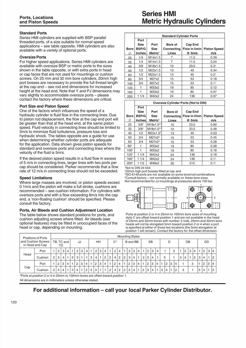
8/7/2019 Hydraulic Fundamental
http://slidepdf.com/reader/full/hydraulic-fundamental 42/52
For additional information – call your local Parker Cylinder Distributor.
20
Standard Cylinder Ports
Piston Speed
m/s
0.39
0.24
0.31
0.34
0.21
0.18
0.11
0.12
0.07
0.07
Standard PortsSeries HMI cylinders are supplied with BSP parallelthreaded ports, of a size suitable for normal speedapplications – see table opposite. HMI cylinders are alsoavailable with a variety of optional ports.
Oversize PortsFor higher speed applications. Series HMI cylinders areavailable with oversize BSP or metric ports to the sizesshown in the table opposite, or with extra ports in heador cap faces that are not used for mountings or cushionscrews. On 25 mm and 32 mm bore cylinders, 20mm highport bosses are necessary to provide the full thread lengthat the cap end – see rod end dimensions for increasedheight at the head end. Note that Y and PJ dimensions mayvary slightly to accommodate oversize ports – pleasecontact the factory where these dimensions are critical.
Port Size and Piston SpeedOne of the factors which inuences the speed of a hydraulic cylinder is uid ow in the connecting lines. Due
to piston rod displacement, the ow at the cap end port willbe greater than that at the head end, at the same pistonspeed. Fluid velocity in connecting lines should be limited to5m/s to minimize uid turbulence, pressure loss and hydraulic shock. The tables opposite are a guide for usewhen determining whether cylinder ports are adequatefor the application. Data shown gives piston speeds forstandard and oversize ports and connecting lines where thevelocity of the uid is 5m/s.
If the desired piston speed results in a uid ow in excessof 5 m/s in connecting lines, larger lines with two ports percap should be considered. Parker recommends that a owrate of 12 m/s in connecting lines should not be exceeded.
Speed LimitationsWhere large masses are involved, or piston speeds exceed0.1m/s and the piston will make a full stroke, cushions arerecommended – see cushion information. For cylinders withoversize ports and with a ow exceeding 8m/s into the capend, a ‘non-oating cushion’ should be specied. Pleaseconsult the factory.
Ports, Air Bleeds and Cushion Adjustment LocationThe table below shows standard positions for ports, andcushion adjusting screws where tted. Air bleeds (seeoptional features) may be tted in unoccupied faces of thehead or cap, depending on mounting.
Series HMIMetric Hydraulic Cylinders
Ports, Locationsand Piston Speeds
1Not to DIN 24 554220mm high port bosses tted at cap end3ISO 6149 ports are not available on some bore/rod combinations4
Consult factory – not normally available on these bore sizesNot recommended for JJ mountings at pressures above 100 bar
Bore of
Connecting
Lines
7
7
10
13
13
15
15
19
19
24
Bore
25
32
40
50
63
80
100
125
160
200
Port
Size
BSP/G
Inches
1/4
1/4
3/8
1/2
1/2
3/4
3/4
1
1
1 1/4
Cap End
Flow in l/min
@ 5m/s
11.5
11.5
23.5
40
40
53
53
85
85
136
Port
Size
Metric1
M14x1.5
M14x1.5
M18x1.5
M22x1.5
M22x1.5
M27x2
M27x2
M33x2
M33x2
M42x2
Oversize Cylinder Ports (Not to DIN)
Piston Speed
m/s0.80
0.48
0.53
0.45
0.28
0.28
0.18
0.18
0.11
0.11
Bore of
Connecting
Lines
10
10
13
15
15
19
19
24
24
30
Bore
25
32
40
50
63
804
1004
1254
1604
2004
Port
Size
BSP/G
Inches3/82
3/82
1/2
3/4
3/4
1
1
1 1/4
1 1/4
1 1/2
Cap End
Flow in l/min
@ 5m/s23.5
23.5
40
53
53
85
85
136
136
212
Port
Size
Metric1
M18x1.52,3
M18x1.52,3
M22x1.53
M27x23
M27x23
M33x2
M33x2
M42x2
M42x2
M48x2
4 2
1
3
Positions of Ports
Mounting Styles
and Cushion Screws TB, TC and JJ HH C5 B and BB SB D DB DD in Head and Cap TD
Port 1 2 3 4 1 2 3 4 1 2 3 4 1 2 4 1 2 3 4 1 2 3 4 1 3 1 2 3 4 1 2 3 4 Head
Cushion 2 3 4 1 3 3 1 1 3 4 1 2 2 4 2 2 3 4 1 2 3 4 1 3 1 3 4 1 2 3 4 1 2
Port 1 2 3 4 1 2 3 4 1 2 3 4 1 2 4 1 2 3 4 1 2 3 4 1 2 3 4 1 3 1 2 3 4Cap
Cushion 2 3 4 1 3 4 1 2 3 3 1 1 2 4 2 2 3 4 1 2 3 4 1 3 4 1 2 3 1 3 4 1 2
All dimensions are in millimeters unless otherwise stated.
5Ports at position 2 or 4 in 25mm to 100mm bores are oset toward position 1.
Ports at position 2 or 4 in 25mm to 100mm bore sizes of mountingstyle C are oset toward position 1 and are not available in the headof 25mm and 32mm bores with number 2 rods. 25mm and 32mm boreheads will not be elongated 5mm toward position 2 or 4 when a portis specied at either of those two locations (the 5mm elongation at position 1 will remain). Contact the factory for the oset dimension.
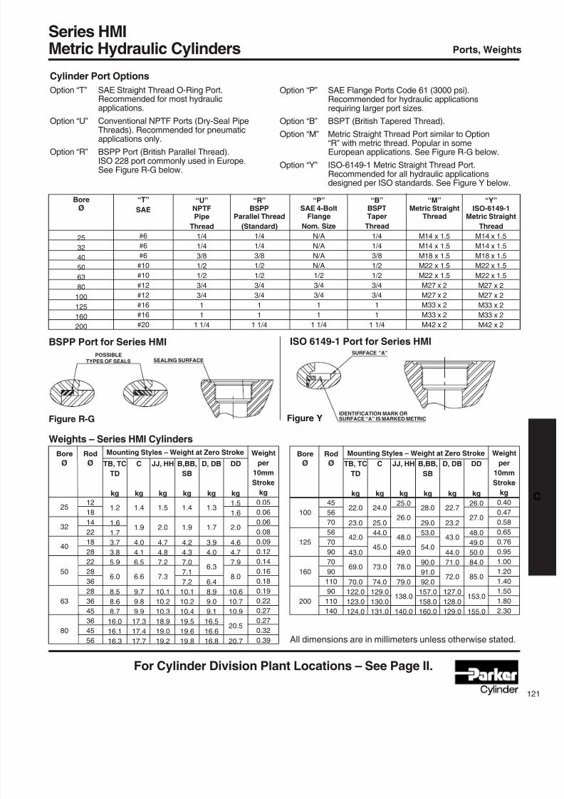
8/7/2019 Hydraulic Fundamental
http://slidepdf.com/reader/full/hydraulic-fundamental 43/52
For Cylinder Division Plant Locations – See Page II.
Cylinder Port Options
Option “T” SAE Straight Thread O-Ring Port.Recommended for most hydraulicapplications.
Option “U” Conventional NPTF Ports (Dry-Seal PipeThreads). Recommended for pneumaticapplications only.
Option “R” BSPP Port (British Parallel Thread).ISO 228 port commonly used in Europe.See Figure R-G below.
Series HMIMetric Hydraulic Cylinders Ports, Weights
Option “P” SAE Flange Ports Code 61 (3000 psi).Recommended for hydraulic applicationsrequiring larger port sizes.
Option “B” BSPT (British Tapered Thread).
Option “M” Metric Straight Thread Port similar to Option“R” with metric thread. Popular in someEuropean applications. See Figure R-G below.
Option “Y” ISO-6149-1 Metric Straight Thread Port.Recommended for all hydraulic applicationsdesigned per ISO standards. See Figure Y below.
“R”BSPP
Parallel Thread
(Standard)
1/4
1/4
3/8
1/2
1/23/4
3/4
1
1
1 1/4
“U”NPTFPipe
Thread
1/4
1/4
3/8
1/2
1/23/4
3/4
1
1
1 1/4
“T”
SAE
#6
#6
#6
#10
#10#12
#12
#16
#16
#20
BoreØ
25
32
40
50
63
80
100
125
160
200
“Y”ISO-6149-1
Metric Straight
Thread
M14 x 1.5
M14 x 1.5
M18 x 1.5
M22 x 1.5
M22 x 1.5M27 x 2
M27 x 2
M33 x 2
M33 x 2
M42 x 2
“M”Metric Straight
Thread
M14 x 1.5
M14 x 1.5
M18 x 1.5
M22 x 1.5
M22 x 1.5M27 x 2
M27 x 2
M33 x 2
M33 x 2
M42 x 2
“B”BSPTTaper
Thread
1/4
1/4
3/8
1/2
1/23/4
3/4
1
1
1 1/4
“P”SAE 4-Bolt
Flange
Nom. Size
N/A
N/A
N/A
N/A
1/23/4
3/4
1
1
1 1/4
BSPP Port for Series HMI
Figure R-G
ISO 6149-1 Port for Series HMI
Figure Y
POSSIBLE
TYPES OF SEALS SEALING SURFACE
B,BB,
SB
kg
1.4
1.9
4.2
4.3
7.0
7.1
7.2
10.1
10.2
10.4
19.5
19.6
19.8
C
kg
1.4
1.9
4.0
4.1
6.5
6.6
9.7
9.8
9.9
17.3
17.4
17.7
DD
kg
1.5
1.6
2.0
4.6
4.7
7.9
8.0
10.6
10.7
10.9
20.5
20.7
Bore
Ø
25
32
40
50
63
80
Rod
Ø
12
18
14
22
18
28
22
28
36
28
36
45
36
45
56
D, DB
kg
1.3
1.7
3.9
4.0
6.3
6.4
8.9
9.0
9.1
16.5
16.6
16.8
Weight
per
10mm
Stroke
kg
0.05
0.06
0.06
0.08
0.09
0.12
0.14
0.16
0.18
0.19
0.22
0.27
0.27
0.32
0.39
JJ, HH
kg
1.5
2.0
4.7
4.8
7.2
7.3
10.1
10.2
10.3
18.9
19.0
19.2
TB, TC
TD
kg
1.2
1.6
1.7
3.7
3.8
5.9
6.0
8.5
8.6
8.7
16.0
16.1
16.3
Mounting Styles – Weight at Zero Stroke
Weights – Series HMI Cylinders
All dimensions are in millimeters unless otherwise stated.
IDENTIFICATION MARK OR
SURFACE “A” IS MARKED METRIC
SURFACE “A”
B,BB,
SB
kg
28.0
29.0
53.0
54.0
90.0
91.0
92.0
157.0
158.0
160.0
C
kg
24.0
25.0
44.0
45.0
73.0
74.0
129.0
130.0
131.0
DD
kg
26.0
27.0
48.0
49.0
50.0
84.0
85.0
153.0
155.0
Bore
Ø
100
125
160
200
Rod
Ø
45
56
70
56
70
90
70
90
110
90
110
140
D, DB
kg
22.7
23.2
43.0
44.0
71.0
72.0
127.0
128.0
129.0
Weight
per
10mm
Stroke
kg
0.40
0.47
0.58
0.65
0.76
0.95
1.00
1.20
1.40
1.50
1.80
2.30
JJ, HH
kg
25.0
26.0
48.0
49.0
78.0
79.0
138.0
140.0
TB, TC
TD
kg
22.0
23.0
42.0
43.0
69.0
70.0
122.0
123.0
124.0
Mounting Styles – Weight at Zero Stroke
8/7/2019 Hydraulic Fundamental
http://slidepdf.com/reader/full/hydraulic-fundamental 44/52
For additional information – call your local Parker Cylinder Distributor.
22
Seals and Fluid Data
Series HMIMetric Hydraulic Cylinders
Seals and Fluids,Optional Features
Operating Medium
Sealingmaterialsusedinthestandardcylinderaresuitablefor use with most petroleum-based hydraulic uids.
Specialsealsareavailableforusewithwater-glycolorwater-in-oil emulsions, and with uids such as re-resistantsyntheticphosphateesterandphosphateester-based uids.
Ifthereisanydoubtregardingsealcompatibilitywiththeoperating medium, please consult the factory.
Thetableaboveisaguidetothesealingcompoundsandoperatingparametersofthematerialsusedforstandardandoptionalrodgland,pistonandbodyseals
Temperature
Standardsealscanbeoperatedattemperaturesbetween-20°C and +80°C. Where operating conditions result intemperatureswhichexceedtheselimits,specialsealcompoundsmayberequiredtoensuresatisfactoryservicelife – please consult the factory.
Special Seals
Group 1 seals are tted as standard to HMI cylinders. For
otherduties,theoptionalsealgroup5isavailable–pleasesee the cylinder order code for HMI (ISO) cylinders. Specialseals,inadditiontothoseshowninthetableabove,canalso be supplied. Please insert an S (Special) in the ordercode and specify uid medium when ordering.
Water Service
Specialcylindersareavailableforusewithwaterastheuid medium. Modications include a stainless steel pistonrod with lipseal piston, and plating of internal surfaces.When ordering, please specify the maximum operatingpressure or load/speed conditions.
Warranty
Parker Hannin warrants cylinders modied for use withwater or water base uids to be free of defects in materialsand workmanship, but cannot accept responsibility forprematurefailurecausedbycorrosion,electrolysisormineral deposits in the cylinder.
Metallic Rod WipersMetallic rod wipers replace the standard wiper seal, andarerecommendedwheredustorsplashingsmightdam-age the wiper seal material. Metallic rod wipers do notaect cylinder dimensions.
Proximity SensorsEPS proximity switches can be tted to give reliable endof stroke signals.
Position Feedback Linearpositiontransducersofvarioustypesareavailablefor Series HMI cylinders. Please contact the factory forfurther details.
Rod End BellowsUnprotectedpistonrodsurfaceswhichareexposedtocontaminantswithairhardeningpropertiescanbepro-tected by rod end bellows. Longer rod extensions arerequiredtoaccommodatethecollapsedlengthofthe
bellows. Please consult the factory for further information.
Group
1
5
Seal Materials – a combination of:
Nitrile (NBR), PTFE,
enhanced polyurethane (AU)
Fluorocarbon elastomer (FPM)
Fluorocarbon, PTFE
Fluid Medium to ISO 6743/4-1982
Mineral oil HH, HL, HLP, HLP-D, HM, HV, MIL-H-5606 oil, nitrogen
Fire resistant uids based on phosphate esters (HFD-R)
Also suitable for hydraulic oil at high temperatures/environments.
Not suitable for use with Skydrol.
See uid manufacturer’s recommendations.
Temperature Range
-20°Cto+80°C
-20°Cto+150°C
Low Friction Seals
For applications where very low friction and an absenceof stick-slip are important, the option of low friction seals isavailable. Please consult the factory.
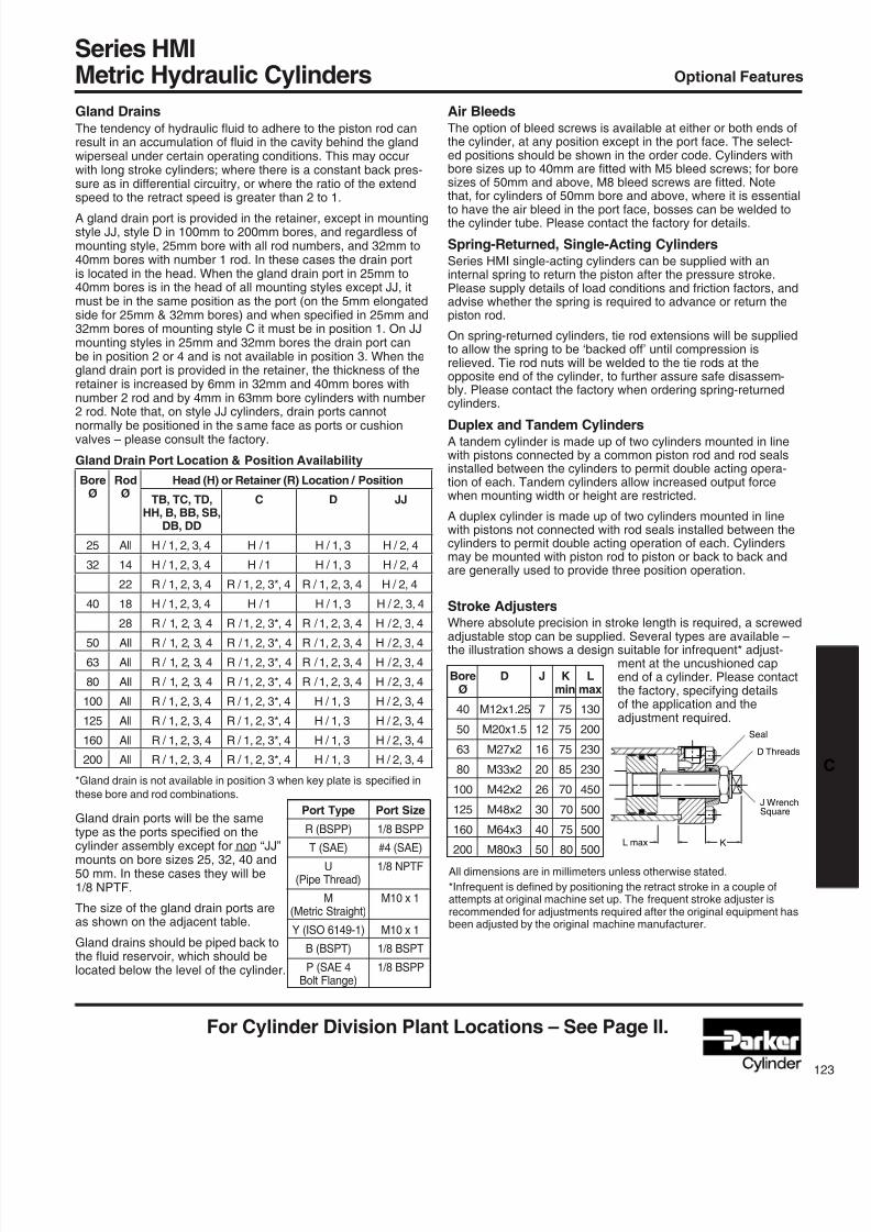
8/7/2019 Hydraulic Fundamental
http://slidepdf.com/reader/full/hydraulic-fundamental 45/52
For Cylinder Division Plant Locations – See Page II.
Series HMIMetric Hydraulic Cylinders Optional Features
Gland DrainsThe tendency of hydraulic uid to adhere to the piston rod canresult in an accumulation of uid in the cavity behind the glandwiperseal under certain operating conditions. This may occurwith long stroke cylinders; where there is a constant back pres-sure as in dierential circuitry, or where the ratio of the extendspeed to the retract speed is greater than 2 to 1.
A gland drain port is provided in the retainer, except in mountingstyle JJ, style D in 100mm to 200mm bores, and regardless ofmounting style, 25mm bore with all rod numbers, and 32mm to40mm bores with number 1 rod. In these cases the drain portis located in the head. When the gland drain port in 25mm to40mm bores is in the head of all mounting styles except JJ, itmust be in the same position as the port (on the 5mm elongatedside for 25mm & 32mm bores) and when specied in 25mm and32mm bores of mounting style C it must be in position 1. On JJmounting styles in 25mm and 32mm bores the drain port canbe in position 2 or 4 and is not available in position 3. When thegland drain port is provided in the retainer, the thickness of theretainer is increased by 6mm in 32mm and 40mm bores withnumber 2 rod and by 4mm in 63mm bore cylinders with number2 rod. Note that, on style JJ cylinders, drain ports cannot
normally be positioned in the same face as ports or cushionvalves – please consult the factory.
Air BleedsThe option of bleed screws is available at either or both ends ofthe cylinder, at any position except in the port face. The select-ed positions should be shown in the order code. Cylinders withbore sizes up to 40mm are tted with M5 bleed screws; for boresizes of 50mm and above, M8 bleed screws are tted. Notethat, for cylinders of 50mm bore and above, where it is essential
to have the air bleed in the port face, bosses can be welded tothe cylinder tube. Please contact the factory for details.
Spring-Returned, Single-Acting CylindersSeries HMI single-acting cylinders can be supplied with aninternal spring to return the piston after the pressure stroke.Please supply details of load conditions and friction factors, andadvise whether the spring is required to advance or return thepiston rod.
On spring-returned cylinders, tie rod extensions will be suppliedto allow the spring to be ‘backed o’ until compression is relieved. Tie rod nuts will be welded to the tie rods at theopposite end of the cylinder, to further assure safe disassem-bly. Please contact the factory when ordering spring-returnedcylinders.
Duplex and Tandem CylindersA tandem cylinder is made up of two cylinders mounted in linewith pistons connected by a common piston rod and rod sealsinstalled between the cylinders to permit double acting opera-tion of each. Tandem cylinders allow increased output forcewhen mounting width or height are restricted.
A duplex cylinder is made up of two cylinders mounted in linewith pistons not connected with rod seals installed between thecylinders to permit double acting operation of each. Cylindersmay be mounted with piston rod to piston or back to back andare generally used to provide three position operation.
All dimensions are in millimeters unless otherwise stated.
*Infrequent is dened by positioning the retract stroke in a couple ofattempts at original machine set up. The frequent stroke adjuster isrecommended for adjustments required after the original equipment hasbeen adjusted by the original machine manufacturer.
Port Type Port Size
R (BSPP) 1/8 BSPP
T (SAE) #4 (SAE)
U 1/8 NPTF(Pipe Thread)
M M10 x 1(Metric Straight)
Y (ISO 6149-1) M10 x 1
B (BSPT) 1/8 BSPT
P (SAE 4 1/8 BSPPBolt Flange)
Bore D J K LØ min max
40 M12x1.25 7 75 130
50 M20x1.5 12 75 200
63 M27x2 16 75 230
80 M33x2 20 85 230
100 M42x2 26 70 450
125 M48x2 30 70 500
160 M64x3 40 75 500
200 M80x3 50 80 500
Stroke AdjustersWhere absolute precision in stroke length is required, a screwed
adjustable stop can be supplied. Several types are available –the illustration shows a design suitable for infrequent* adjust-
ment at the uncushioned capend of a cylinder. Please contactthe factory, specifying details of the application and theadjustment required.
Seal
D Threads
L max
J WrenchSquare
K
Gland drain ports will be the sametype as the ports specied on the
cylinder assembly except for non “JJ”mounts on bore sizes 25, 32, 40 and 50 mm. In these cases they will be1/8 NPTF.
The size of the gland drain ports areas shown on the adjacent table.
Gland drains should be piped back tothe uid reservoir, which should be located below the level of the cylinder.
Gland Drain Port Location & Position Availability
BoreØ
RodØ
Head (H) or Retainer (R) Location / Position
TB, TC, TD,HH, B, BB, SB,
DB, DD
C D JJ
25 All H / 1, 2, 3, 4 H / 1 H / 1, 3 H / 2, 4
32 14 H / 1, 2, 3, 4 H / 1 H / 1, 3 H / 2, 4
22 R / 1, 2, 3, 4 R / 1, 2, 3*, 4 R / 1, 2, 3, 4 H / 2, 4
40 18 H / 1, 2, 3, 4 H / 1 H / 1, 3 H / 2, 3, 4
28 R / 1, 2, 3, 4 R / 1, 2, 3*, 4 R / 1, 2, 3, 4 H / 2, 3, 4
50 All R / 1, 2, 3, 4 R / 1, 2, 3*, 4 R / 1, 2, 3, 4 H / 2, 3, 4
63 All R / 1, 2, 3, 4 R / 1, 2, 3*, 4 R / 1, 2, 3, 4 H / 2, 3, 4
80 All R / 1, 2, 3, 4 R / 1, 2, 3*, 4 R / 1, 2, 3, 4 H / 2, 3, 4
100 All R / 1, 2, 3, 4 R / 1, 2, 3*, 4 H / 1, 3 H / 2, 3, 4
125 All R / 1, 2, 3, 4 R / 1, 2, 3*, 4 H / 1, 3 H / 2, 3, 4
160 All R / 1, 2, 3, 4 R / 1, 2, 3*, 4 H / 1, 3 H / 2, 3, 4
200 All R / 1, 2, 3, 4 R / 1, 2, 3*, 4 H / 1, 3 H / 2, 3, 4
*Gland drain is not available in position 3 when key plate is specied inthese bore and rod combinations.
8/7/2019 Hydraulic Fundamental
http://slidepdf.com/reader/full/hydraulic-fundamental 46/52
Series 3H Large BoreHigh Pressure Hydraulic Cylinders
For additional information – call your local Parker Cylinder Distributor.
24
Rod End Data
Rod end dimension symbols as shown comply with the NationalFluid Power Association dimensional code. The following chartindicates the symbols used in this catalog.
Description Symbol
Thread diameter and pitch KK
Length of thread A
Length of Rod Extension from LAF (Male Thread)
face of head to end of retracted rod WF (Female Thread)
Two rod ends for Series 3H cylinders are offered as shown onthe dimension pages of this catalog. They are Parker styles 4and 9 and are optional without price penalty. If a rod end style isnot specified, the Parker style 4 (N.F.P.A. Style SM) will besupplied.
International Rod End Threads
Piston rod threads to meet international requirements areavailable at extra cost. Parker cylinders can be supplied withBritish standard fine (W) or metric (M). To order, specify in modelnumber. For dimensions, consult factory.
Special Rod Ends
If a rod end configuration other than the standard styles 4 and 9is required, such special rod ends can be provided. The designa-tion “Style 3” is assigned to such specials and is incorporated inthe cylinder model number. To order, specify “Style 3” and givedesired dimensions for KK, A, or LAF, or WF if female end. Ifotherwise special, send a dimensioned sketch.
Rod End Boots
Are available on request: Consult factory for details.
FIXED MOUNTS which absorb PIVOT MOUNTS which absorb FIXED MOUNTS which do not
force on cylinder centerline. force on cylinder centerline. absorb force on centerline.
Mtg. Styles HH, HB, E Mtg. Styles DD, D, DB, BB Mtg. Style C
Mtg. Styles JJ, JB, E Mtg. Styles BB, DD, D, DB Mtg. Style C
Application DataMounting ClassesRod End DataOptions
Application DataThe proper application of a fluid power cylinder requires consider-ation of the operating pressure, the fluid medium, the mountingstyle, the length of stroke, the type of piston rod connection to theload, thrust or tension loading on the rod, mounting attitude, the
speed of stroke, and how the load in motion will be stopped. Theinformation given here provides data to evaluate averageapplications for Series “3H” Hydraulic Cylinders, and will assist
you in proper cylinder selection.
Mounting Classes
Standard mountings for series “3H” power cylinders fall into twobasic classes and three groups. The two classes can be summa-rized as follows:
Class 1 – Straight Line Force Transfer (Groups 1 and 3).
Class 2 – Pivot Force Transfer (Group 2). Pivot mountingspermit a cylinder to change it alignment in one plane.
Because a cylinder’s mounting directly affects the maximumpressure at which the cylinder can be used, the chart belowshould be helpful in the selection of the proper mounting combi-nation for your application. Stroke length, piston rod connection toload, extra piston rod length over standard, etc., should beconsidered for thrust loads. Alloy steel mounting bolts arerecommended for all mounting styles, and thrust keys arerecommended for Group 3.
Special Assemblies From Standard PartsEach dimensioned drawing in this catalog has position numbers shownon the end view to identify the four sides of the cylinder. These aid incommunications and simplify the writing of specifications that coverchanges in port positions, etc. Following are several suggested specialassemblies that can be made up from standard parts.
a) By calling out the position numbers for the desired locations for headand cap ports, some mounting styles can be assembled with portslocated at 90° or 180° from standard. In such special assemblies,the cushion needle and check valves are also repositioned sincetheir relation with the port position does not change.
b) Standard mountings in different combinations can be provided: forexample, Style JJ mounting on head end with Style C on the cap
end. This would be made up from standard parts and would bedesignated Model JJC-3H14.
Maximum Pressure Rating
Single-Acting Cylinders
Double-acting “3H” cylindersare supplied as standard.They can also be used assingle-acting cylinders wherefluid force is applied to onlyone side of the piston, withthe load or other externalforces acting to “return” thepiston after pressure isexhausted. It is necessary toplumb the unused port tankto collect any piston bypass.
Series “3H” cylinders are
recommended for pressuresto 3000 p.s.i. for heavy-dutyservice with hydraulic oil.The 4:1 design factor ratingsshown are based on tensilestrength of material and arefor code 1 rod dia. only.Design factors at otherpressures can be calculatedfrom this rating. In addition,mounting styles, stroke, etc.,
should be considered because of the limiting effect they may have onthese ratings.
Inches
41 / 2
51 / 2
7
8
9
10
PSI
2720
2580
2320
2750
2900
2640
PSI
3000
3000
3000
3000
3000
3000
4:1Design Heavy-
Rod Factor DutyBore Dia. (Tensile) Service
Inches
10
12
14
16
18
20
Class 1 — Group 1 Class 2 — Group 2 Class 1— Group 3
Heavy-DutyService
For Thrust Loads
For Tension Loads
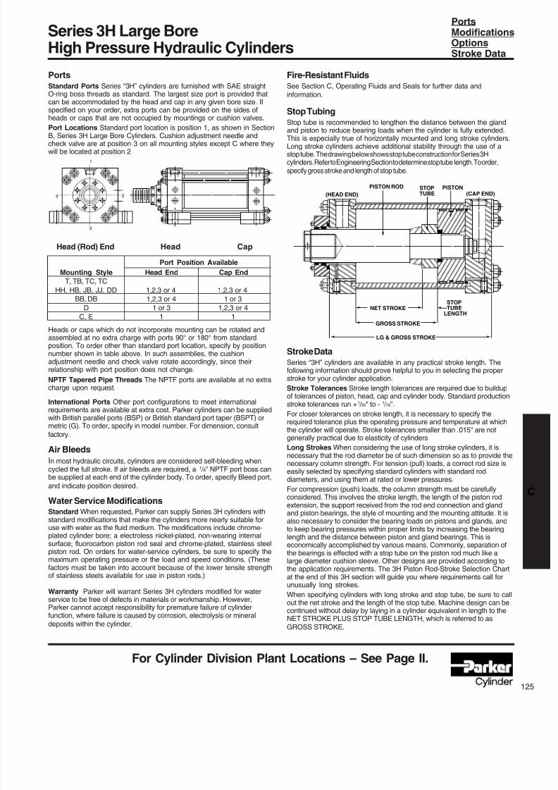
8/7/2019 Hydraulic Fundamental
http://slidepdf.com/reader/full/hydraulic-fundamental 47/52
Series 3H Large BoreHigh Pressure Hydraulic Cylinders
For Cylinder Division Plant Locations – See Page II.
NET STROKE
GROSS STROKE
LG & GROSS STROKE
STOPTUBE
LENGTH
(HEAD END)
PISTON ROD STOPTUBE
PISTON(CAP END)
Fire-Resistant FluidsSee Section C, Operating Fluids and Seals for further data andinformation.
Stop TubingStop tube is recommended to lengthen the distance between the glandand piston to reduce bearing loads when the cylinder is fully extended.This is especially true of horizontally mounted and long stroke cylinders.Long stroke cylinders achieve additional stability through the use of astop tube.The drawing below shows stop tube construction for Series 3Hcylinders. Refer to Engineering Section to determine stop tube length. To order,specify gross stroke and length of stop tube.
Stroke DataSeries “3H” cylinders are available in any practical stroke length. Thefollowing information should prove helpful to you in selecting the properstroke for your cylinder application.
Stroke Tolerances Stroke length tolerances are required due to buildupof tolerances of piston, head, cap and cylinder body. Standard production
stroke tolerances run +1
/ 32" to -1
/ 16".For closer tolerances on stroke length, it is necessary to specify therequired tolerance plus the operating pressure and temperature at whichthe cylinder will operate. Stroke tolerances smaller than .015" are notgenerally practical due to elasticity of cylinders
Long Strokes When considering the use of long stroke cylinders, it isnecessary that the rod diameter be of such dimension so as to provide thenecessary column strength. For tension (pull) loads, a correct rod size iseasily selected by specifying standard cylinders with standard roddiameters, and using them at rated or lower pressures.
For compression (push) loads, the column strength must be carefullyconsidered. This involves the stroke length, the length of the piston rodextension, the support received from the rod end connection and glandand piston bearings, the style of mounting and the mounting attitude. It isalso necessary to consider the bearing loads on pistons and glands, andto keep bearing pressures within proper limits by increasing the bearinglength and the distance between piston and gland bearings. This iseconomically accomplished by various means. Commonly, separation ofthe bearings is effected with a stop tube on the piston rod much like alarge diameter cushion sleeve. Other designs are provided according tothe application requirements. The 3H Piston Rod-Stroke Selection Chartat the end of this 3H section will guide you where requirements call forunusually long strokes.
When specifying cylinders with long stroke and stop tube, be sure to callout the net stroke and the length of the stop tube. Machine design can becontinued without delay by laying in a cylinder equivalent in length to theNET STROKE PLUS STOP TUBE LENGTH, which is referred to asGROSS STROKE.
PortsModificationsOptionsStroke Data
PortsStandard Ports Series “3H” cylinders are furnished with SAE straightO-ring boss threads as standard. The largest size port is provided thatcan be accommodated by the head and cap in any given bore size. Ifspecified on your order, extra ports can be provided on the sides ofheads or caps that are not occupied by mountings or cushion valves.
Port Locations Standard port location is position 1, as shown in Section
B, Series 3H Large Bore Cylinders. Cushion adjustment needle andcheck valve are at position 3 on all mounting styles except C where theywill be located at position 2.
Head (Rod) End Head Cap
Port Position Available
Mounting Style Head End Cap EndT, TB, TC, TC
HH, HB, JB, JJ, DD 1,2,3 or 4 1,2,3 or 4
BB, DB 1,2,3 or 4 1 or 3
D 1 or 3 1,2,3 or 4
C, E 1 1
Heads or caps which do not incorporate mounting can be rotated andassembled at no extra charge with ports 90° or 180° from standardposition. To order other than standard port location, specify by positionnumber shown in table above. In such assemblies, the cushionadjustment needle and check valve rotate accordingly, since theirrelationship with port position does not change.
NPTF Tapered Pipe Threads The NPTF ports are available at no extracharge upon request.
International Ports Other port configurations to meet internationalrequirements are available at extra cost. Parker cylinders can be suppliedwith British parallel ports (BSP) or British standard port taper (BSPT) ormetric (G). To order, specify in model number. For dimension, consult
factory.
Air Bleeds
In most hydraulic circuits, cylinders are considered self-bleeding whencycled the full stroke. If air bleeds are required, a 1 / 8" NPTF port boss canbe supplied at each end of the cylinder body. To order, specify Bleed port,
and indicate position desired.
Water Service ModificationsStandard When requested, Parker can supply Series 3H cylinders withstandard modifications that make the cylinders more nearly suitable foruse with water as the fluid medium. The modifications include chrome-plated cylinder bore; a electroless nickel-plated, non-wearing internal
surface; fluorocarbon piston rod seal and chrome-plated, stainless steelpiston rod. On orders for water-service cylinders, be sure to specify themaximum operating pressure or the load and speed conditions. (Thesefactors must be taken into account because of the lower tensile strengthof stainless steels available for use in piston rods.)
Warranty Parker will warrant Series 3H cylinders modified for waterservice to be free of defects in materials or workmanship. However,Parker cannot accept responsibility for premature failure of cylinderfunction, where failure is caused by corrosion, electrolysis or mineraldeposits within the cylinder.
1
2
3
4
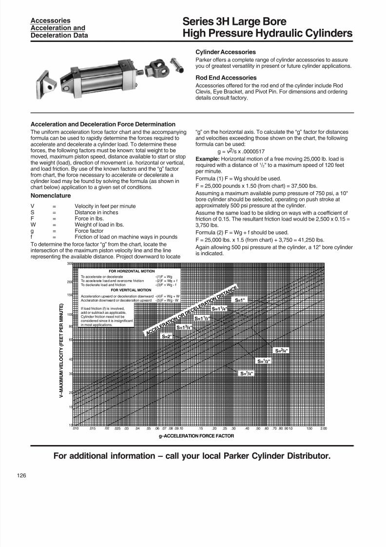
8/7/2019 Hydraulic Fundamental
http://slidepdf.com/reader/full/hydraulic-fundamental 48/52
Series 3H Large BoreHigh Pressure Hydraulic Cylinders
For additional information – call your local Parker Cylinder Distributor.
26
300
200
150
100
80
60
40
30
20
15
10.010 .015 .02 .025 .03 .04 .05 .06 .07 .08 .09.10 .15 .20 .25 .30 .40 .50 .60 .70 .80 .901.0 1.50 2.00
g–ACCELERATION FORCE FACTOR
V – M A X I M U M V
E L O C I T Y ( F E E T P E R M I N U T E )
A C C E L E R A
T I O N O
R D E C
E L E R
A T I O N
D I S T A N
C E
S=2"
S=13 / 4"
S=11 / 2"
S=11 / 4"
S=1"
S=1
/ 4"
S=1 / 2"
S=3 / 4"
FOR HORIZONTAL MOTION
To accelerate or decelerate -(1)F = Wg
To accelerate load and overcome friction -(2)F = Wg + fTo declerate load and friction -(3)F = Wg - f
FOR VERITCAL MOTION
Acceleration upward or deceleration downward -(4)F = Wg + WAccleration downward or deceleration upward -(5)F = Wg - W
If load friction (f) is involved,add or subtract as applicable.Cylinder friction need not beconsidered since it is insignificantin most applications.
Cylinder Accessories
Parker offers a complete range of cylinder accessories to assureyou of greatest versatility in present or future cylinder applications.
Rod End Accessories
Accessories offered for the rod end of the cylinder include Rod
Clevis, Eye Bracket, and Pivot Pin. For dimensions and orderingdetails consult factory.
AccessoriesAcceleration andDeceleration Data
Acceleration and Deceleration Force Determination
The uniform acceleration force factor chart and the accompanyingformula can be used to rapidly determine the forces required toaccelerate and decelerate a cylinder load. To determine theseforces, the following factors must be known: total weight to bemoved, maximum piston speed, distance available to start or stopthe weight (load), direction of movement i.e. horizontal or vertical,and load friction. By use of the known factors and the “g” factorfrom chart, the force necessary to accelerate or decelerate acylinder load may be found by solving the formula (as shown in
chart below) application to a given set of conditions.Nomenclature
V = Velocity in feet per minuteS = Distance in inchesF = Force in lbs.W = Weight of load in lbs.g = Force factorf = Friction of load on machine ways in pounds
To determine the force factor “g” from the chart, locate theintersection of the maximum piston velocity line and the linerepresenting the available distance. Project downward to locate
“g” on the horizontal axis. To calculate the “g” factor for distancesand velocities exceeding those shown on the chart, the followingformula can be used:
g = v2 /s x .0000517
Example: Horizontal motion of a free moving 25,000 lb. load isrequired with a distance of 1 / 2" to a maximum speed of 120 feetper minute.
Formula (1) F = Wg should be used.
F = 25,000 pounds x 1.50 (from chart) = 37,500 lbs.Assuming a maximum available pump pressure of 750 psi, a 10"bore cylinder should be selected, operating on push stroke atapproximately 500 psi pressure at the cylinder.
Assume the same load to be sliding on ways with a coefficient offriction of 0.15. The resultant friction load would be 2,500 x 0.15 =3,750 lbs.
Formula (2) F = Wg + f should be used.
F = 25,000 lbs. x 1.5 (from chart) + 3,750 = 41,250 lbs.
Again allowing 500 psi pressure at the cylinder, a 12" bore cylinderis indicated.
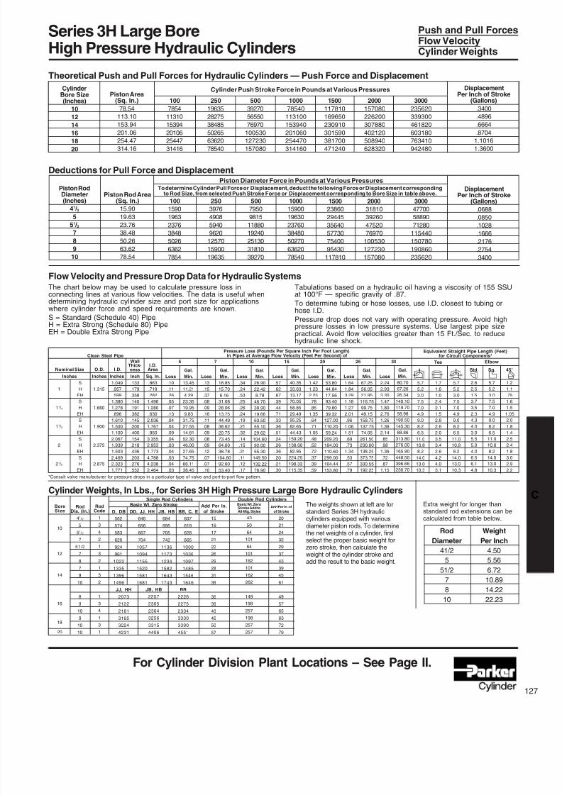
8/7/2019 Hydraulic Fundamental
http://slidepdf.com/reader/full/hydraulic-fundamental 49/52
Series 3H Large BoreHigh Pressure Hydraulic Cylinders
For Cylinder Division Plant Locations – See Page II.
Theoretical Push and Pull Forces for Hydraulic Cylinders — Push Force and Displacement
Deductions for Pull Force and Displacement
Flow Velocity and Pressure Drop Data for Hydraulic Systems
DisplacementPer Inch of Stroke
(Gallons)
.3400
.4896
.6664
.87041.1016
1.3600
CylinderBore Size(Inches)
10
12
14
1618
20
Std.
2.6
2.5
1.5
3.7
3.52.3
4.3
4.0
3.0
5.5
5.0
4.0
6.5
6.1
4.8
RodDia. (In.)
41 / 2
5
51 / 2
7
51/2
7
8
7
8
10
8
9
10
9
10
10
Rod Weight
Diameter Per Inch
41/2 4.50
5 5.56
51/2 6.72
7 10.89
8 14.22
10 22.23
Tabulations based on a hydraulic oil having a viscosity of 155 SSUat 100°F — specific gravity of .87.
To determine tubing or hose losses, use I.D. closest to tubing orhose I.D.
Pressure drop does not vary with operating pressure. Avoid highpressure losses in low pressure systems. Use largest pipe sizepractical. Avoid flow velocities greater than 15 Ft./Sec. to reducehydraulic line shock.
D, DB
562
574
583
620
924
961
1022
1335
1396
1496
.133
.179
.358
.140
.191
.382
.145
.200
.400
.154
.218
.436
.203
.276
.552
.863
.719
.282
1.496
1.280.630
2.036
1.767
.950
3.355
2.953
1.773
4.788
4.238
2.464
Loss
.13
.15
.37
.08
.09
.16
.11
.08
.09
.08
.09
.12
.07
.07
.10
Loss
.34
.24
.53
.25
.26
.24
.19
.21
.32
.14
.15
.21
.11
.12
.17
Loss
.57
.62
.67
.39
.44
.71
.33
.36
.51
.24
.26
.36
.20
.21
.30
Loss
1.42
1.23
2.25
.78
.851.35
.64
.71
1.05
.48
.52
.72
.37
.39
.59
Loss
.10
.11
.26
.05
.07
.13
.04
.04
.09
.04
.03
.04
.03
.04
.03
Gal.
Min.
13.45
11.21
4.39
23.35
19.959.83
31.75
27.55
14.81
52.30
46.00
27.65
74.75
66.11
38.45
1.049
.957
.599
1.380
1.278.896
1.610
1.500
1.100
2.067
1.939
1.503
2.469
2.323
1.771
Push and Pull ForcesFlow VelocityCylinder Weights
100
1590
1963
2376
3848
5026
6362
7854
250
3976
4908
5940
9620
12570
15900
19635
500
7950
9815
11880
19240
25130
31810
39270
Piston RodDiameter(Inches)
41 / 25
51 / 27
8
9
10
Piston Rod Area(Sq. In.)
15.90
19.63
23.76
38.48
50.26
63.62
78.54
1000
15900
19630
23760
38480
50270
63620
78540
1500
23860
29445
35640
57730
75400
95430
117810
2000
31810
39260
47520
76970
100530
127230
157080
3000
47700
58890
71280
115440
150780
190860
235620
DisplacementPer Inch of Stroke
(Gallons)
.0688
.0850
.1028
.1666
.2176
.2754
.3400
Piston Diameter Force in Pounds at Various PressuresTo determine Cylinder Pull Force or Displacement, deduct the following Force or Displacement corresponding
to Rod Size, from selected Push Stroke Force or Displacement corresponding to Bore Size in table above.
The chart below may be used to calculate pressure loss inconnecting lines at various flow velocities. The data is useful whendetermining hydraulic cylinder size and port size for applicationswhere cylinder force and speed requirements are known.
S = Standard (Schedule 40) PipeH = Extra Strong (Schedule 80) PipeEH = Double Extra Strong Pipe
Loss
1.64
1.84
3.29
1.18
1.272.01
.96
1.06
1.51
.69
.73
1.34
.53
.57
.79
Loss
2.24
2.93
3.30
1.47
1.802.76
1.26
1.36
2.14
.85
.98
1.36
.72
.87
1.15
5.7
5.2
3.0
7.5
7.04.9
9.0
8.2
6.5
11.0
10.8
8.2
14.0
13.0
10.3
1.7
1.6
1.0
2.4
2.11.5
2.8
2.6
2.0
3.5
3.4
2.6
4.2
4.0
3.1
Sq.
5.7
5.2
3.0
7.5
7.04.9
9.0
8.2
6.5
11.0
10.8
8.2
14.0
13.0
10.3
45°
1.2
1.1
.75
1.6
1.51.05
2.0
1.8
1.4
2.5
2.4
1.8
3.0
2.9
2.2
Gal.
Min.
18.85
15.70
6.16
31.68
28.0613.75
44.49
38.62
20.75
73.45
64.60
38.78
104.80
92.60
53.40
Gal.
Min.
26.90
22.42
8.78
46.70
39.9019.66
63.50
55.10
29.62
104.60
92.00
55.30
149.50
132.22
76.90
Gal.
Min.
40.35
33.63
13.17
70.05
58.8529.49
95.25
82.65
44.43
159.20
138.00
82.95
224.25
198.33
115.35
Gal.
Min.
53.80
44.84
17.56
93.40
79.8039.32
127.00
110.20
59.24
209.20
184.00
110.60
299.00
164.44
153.80
Gal.
Min.
67.25
56.05
21.95
116.75
99.7549.15
158.75
137.75
74.05
261.50
230.00
138.25
373.75
330.55
192.25
Gal.
Min.
80.70
67.26
26.34
140.10
119.7058.98
190.50
145.30
88.86
313.80
276.00
165.90
448.50
396.66
230.70
5.7
5.2
3.0
7.5
7.04.9
9.0
8.2
6.5
11.0
10.8
8.2
14.0
13.0
10.3
ElbowTee
Equivalent Straight Pipe Length (Feet)for Circuit Components*
Pressure Loss (Pounds Per Square Inch Per Foot Length)in Pipes at Average Flow Velocity (Feet Per Second) of
5 7 10 15 20 25 30
Nominal Size
Inches Inches Sq. In.InchInches
O.D. I.D.
WallThick-ness
I.D.Area
Clean Steel Pipe
*Consult valve manufacturer for pressure drops in a particular type of valve and port-to-port flow pattern.
1
11
/ 4
11 / 2
2
21 / 2
S
H
EH
S
HEH
S
H
EH
S
H
EH
S
H
EH
1.315
1.660
1.900
2.375
2.875
Cylinder Weights, In Lbs., for Series 3H High Pressure Large Bore Hydraulic Cylinders
The weights shown at left are forstandard Series 3H hydrauliccylinders equipped with variousdiameter piston rods. To determinethe net weights of a cylinder, firstselect the proper basic weight forzero stroke, then calculate theweight of the cylinder stroke andadd the result to the basic weight.
BoreSize
10
12
14
16
18
20
RodCode
1
3
4
2
1
3
2
1
3
2
1
3
4
1
3
1
DD, JJ, HH
646
656
667
704
1057
1094
1155
1520
1581
1681
JB, HB
684
695
705
742
1136
1173
1234
1582
1643
1743
BB, C, E
607
619
628
665
1000
1036
1097
1485
1546
1646
Add Per In.
of Stroke
15
16
17
21
22
26
29
28
31
39
35
39
43
45
50
57
Single Rod CylindersBasic Wt. Zero Stroke Basic Wt. Zero
Stroke Add toAll Mtg. Styles
Add Per In. of
of Stroke
20
21
24
32
29
37
43
39
45
61
49
57
65
63
72
79
43
50
64
101
64
101
162
101
162
262
149
198
257
198
257
257
Double Rod Cylinders
Extra weight for longer thanstandard rod extensions can becalculated from table below.
Piston Area(Sq. In.)
78.54
113.10
153.94
201.06254.47
314.16
100
7854
11310
15394
2010625447
31416
250
19635
28275
38485
5026563620
78540
500
39270
56550
76970
100530127230
157080
1000
78540
113100
153940
201060254470
314160
1500
117810
169650
230910
301590381700
471240
2000
157080
226200
307880
402120508940
628320
3000
235620
339300
461820
603180763410
942480
Cylinder Push Stroke Force in Pounds at Various Pressures
JB, HB
2257
2305
2364
3256
3315
4406
JJ, HH
2073
2122
2181
3165
3224
4231
BB
2226
2275
2334
3330
3390
4551
8/7/2019 Hydraulic Fundamental
http://slidepdf.com/reader/full/hydraulic-fundamental 50/52
For additional information – call your local Parker Cylinder Distributor.
28
Recommended Mounting Styles for Rod End StrokeMaximum Stroke and Thrust Loads Connection Case Factor
Cylinder Stroke Chart
Piston Rod — Stroke Selection Chart
Class 1 — Groups 1 or 3Long stroke cylinders for thrust loads should be mountedusing a heavy-duty mounting style at one end, firmly fixedand aligned to take the principal force. Additional mountingshould be specified at the opposite end, which should beused for alignment and support. An intermediate support mayalso be desirable for long stroke cylinders mounted horizon-tally.
Class 2 — Group 2Heavy-Duty Style D — Trunnion on Head
Heavy-Duty Style DD — Intermediate Trunnion
Heavy-Duty Style DB — Trunnion on Cap orStyle BB — Clevis on Cap
Fixed and RigidlyGuided
Pivoted and RigidlyGuided
Supported but notRigidly Guided
Pivoted and RigidlyGuided
Pivoted and RigidlyGuided
Pivoted and RigidlyGuided
.50
.70
2.00
1.00
1.50
2.00
How to Use the ChartThe selection of a piston rod for thrust (push) conditions requires thefollowing steps:
1. Determine the type of cylinder mounting style and rod endconnection to be used. Then consult the chart below and find the“stroke factor” that corresponds to the conditions used.
2. Using this stroke factor, determine the “basic length” from theequation:
Basic Actual StrokeLength
=Stroke
xFactor
The graph is prepared for standard rod extensions beyond the face ofthe gland retainers. For rod extensions greater than standard, add theincrease to the stroke in arriving at the “basic length.”
3. Find the load imposed for the thrust application by multiplying thefull bore area of the cylinder by the system pressure.
4. Enter the graph along the values of “basic length” and “thrust” asfound above and note the point of intersection:
A)The correct piston rod size is read from the diagonally curved linelabeled “Rod Diameter” next above the point of intersection.
B)The required length of stop tube is read from the right of the graphby following the shaded band in which the point of intersection lies.
C) If required length of stop tube is in the region labeled “consultfactory,” submit the following information for an individual analysis:
1) Cylinder mounting style.
2) Rod end connection and method of guiding load.
3) Bore, required stroke, length of rod extension (Dim. “LA”) ifgreater than standard, and series of cylinder used.
4) Mounting position of cylinder. (Note: If at an angle or vertical,specify direction of piston rod.)
5) Operating pressure of cylinder if limited to less than standardpressure for cylinder selected.
WarningPiston rods are not normally designed to absorb bending moments orloads which are perpendicular to the axis of piston rod motion. These
additional loads can cause the piston rod end to fail. If these types ofadditional loads are expected to be imposed on the piston rods, theirmagnitude should be made known to our Engineering Department sothey may be properly addressed. Additionally, cylinder users shouldalways make sure that the piston rod is securely attached to themachine member.
Series 3H Large BoreHigh Pressure Hydraulic Cylinders
3 0 0
2 0 0
2 0
3 0
4 0
5 0
6 0
7 0
8 0
9 0
1 0 0
1 5 , 0 0 0
2
2 . 5 3 4 5 6 7 8 9 1 0 0 , 0 0 0 2 3 4 5 6 7 8
9
I N C H E S O F
S T O P T U B E
1
2
3
4
5
6
7
C O N S U L
T F A C T O R Y
THRUST-POUNDS
B A S I C L E N G T H — I N C H E S
ROD DIA.
4
1
/
2
5
5
1
/
2
7 8 9 1 0
I
II
III
IV
V
VI
8/7/2019 Hydraulic Fundamental
http://slidepdf.com/reader/full/hydraulic-fundamental 51/52
8/7/2019 Hydraulic Fundamental
http://slidepdf.com/reader/full/hydraulic-fundamental 52/52
Hydraulic andPneumatic Cylinders
Safety Guidelines forCylinder Division Products
Parker Safety Guide for Selecting and Using Hydraulic,Pneumatic Cylinders and Their Accessories
WARNING: FAILURE OR IMPROPER SELECTION OR IMPROPER USE OF CYLINDERS AND THEIR RELATEDACCESSORIES CAN CAUSE DEATH, PERSONAL INJURY AND PROPERTY DAMAGE.
Before selecting or using Parker cylinders or related accesso-
ries, it is important that you read, understand and follow thefollowing safety information.
User Responsibility
Due to very wide variety of cylinder applications and cylinderoperating conditions, Parker does not warrant that any particularcylinder is suitable for any specific application. This safety guide doesnot analyze all technical parameters that must be considered inselecting a product. The hydraulic and pneumatic cylinders outlined inthis catalog are designed to Parker’s design guide lines and do notnecessarily meet the design guide lines of other agencies such asAmerican Bureau of Shipping, ASME Pressure Vessel Code etc. Theuser, through its own analysis and testing, is solely responsible for:
• Making the final selection of the cylinders and relatedaccessories.
• Determining if the cylinders are required to meet specific designrequirements as required by the Agency(s) or industry standardscovering the design of the user’s equipment.
• Assuring that the user’s requirements are met, OSHA requirementsare met, and safety guidelines from the applicable agencies suchas but not limited to ANSI are followed and that the use presents nohealth or safety hazards.
• Providing all appropriate health and safety warnings on theequipment on which the cylinders are used.
Seals
Part of the process of selecting a cylinder is the selection of sealcompounds. Before making this selection read the Operating Fluidsand Seals section in this catalog or in the Application EngineeringData section of the current 0106 or 0900P series catalogs, or contactour engineering department.
The application of cylinders may allow fluids such as cutting fluids,wash down fluids etc. to come in contact with the external area of thecylinder. These fluids may attack the piston rod wiper and or theprimary seal and must be taken into account when selecting and
specifying seal compounds.Dynamic seals will wear. The rate of wear will depend on manyoperating factors. Wear can be rapid if a cylinder is mis-aligned or ifthe cylinder has been improperly serviced. The user must take sealwear into consideration in the application of cylinders.
Piston Rods
Possible consequences of piston rod failure or separation of thepiston rod from the piston include, but are not limited to are:
• Piston rod and or attached load thrown off at high speed.
• High velocity fluid discharge.
• Piston rod extending when pressure is applied in the piston retractmode.
Piston rods or machine members attached to the piston rod maymove suddenly and without warning as a consequence of otherconditions occurring to the machine such as, but not limited to:
• Unexpected detachment of the machine member from the pistonrod.
• Failure of the pressurized fluid delivery system (hoses, fittings,valves, pumps, compressors) which maintain cylinder position.
• Catastrophic cylinder seal failure leading to sudden loss ofpressurized fluid.
• Failure of the machine control system.
Piston rods are not normally designed to absorb bending moments
or loads which are perpendicular to the axis of piston rod motion.These additional loads can cause the piston rod to fail. If these typesof additional loads are expected to be imposed on the piston rod,their magnitude should be made known to our engineering depart-ment.
The cylinder user should always make sure that the piston rod issecurely attached to the machine member.
On occasion cylinders are ordered with double rods (a piston rodextended from both ends of the cylinder). In some cases a stop isthreaded on to one of the piston rods and used as an external strokeadjuster. On occasions spacers are attached to the machinemember connected to the piston rod and also used as a strokeadjuster. In both cases the stops will create a pinch point and theuser should consider appropriate use of guards. If these externalstops are not perpendicular to the mating contact surface, or ifdebris is trapped between the contact surfaces, a bending momentwill be placed on the piston rod, which can lead to piston rod failure.
An external stop will also negate the effect of cushioning and willsubject the piston rod to impact loading. Those two (2) conditionscan cause piston rod failure. Internal stroke adjusters are availablewith and without cushions. The use of external stroke adjustersshould be reviewed with our engineering department.
The piston rod to piston and the stud to piston rod threadedconnections are secured with an anaerobic adhesive. The strengthof the adhesive decreases with increasing temperature. Cylinderwhich can be exposed to temperatures above +250°F (+121°C) areto be ordered with a non studded piston rod and a pinned piston torod joint.
Cushions
Cushions should be considered for cylinder applications when thepiston velocity is expected to be over 4 inches/second.
Cylinder cushions are normally designed to absorb the energy of alinear applied load. A rotating mass has considerably more energythan the same mass moving in a linear mode. Cushioning for arotating mass application should be review by our engineeringdepartment.
Cylinder Mountings
Some cylinder mounting configurations may have certain limitationssuch as but not limited to minimum stroke for side or foot mountingcylinders or pressure de-ratings for certain flange mounts. Carefullyreview the catalog for these types of restrictions.
Always mount cylinders using the largest possible high tensile alloysteel socket head cap screws that can fit in the cylinder mountingholes and torque them to the manufacturer’s recommendations fortheir size.
Port Fittings
Hydraulic cylinders applied with meter out or deceleration circuitsare subject to intensified pressure at piston rod end.
The rod end pressure is approximately equal to:
operating pressure x effective cap end area
effective rod end piston area
Contact your connector supplier for the pressure rating of individualconnectors.
Cylinder Modifications or Repairs
Cylinders as shipped from the factory are not to be disassembled