Embed Size (px)
Citation preview

Pneumatic Series
Hydraulic Series
Valve / CouplerHydraulic Unit
Cautions / Others
High-PowerSeries
Manual OperationAccessories
Hole Clamp
SFASFC
Link Clamp
LKALKCLKWLM/LJTMA-2TMA-1
Work Support
LDLCTNCTC
LLW
Air SensingLift Cylinder
Compact Cylinder
LLLLRLLUDPDRDSDT
Block Cylinder
DBADBC
Control Valve
BZLBZTBZX/JZG
Pallet Clamp
VSVT
Expansion Locating Pin
VFLVFMVFJVFK
FPFQ
Pull Stud Clamp
FVAFVDFVC
Centering Vise
DWA/DWB
CustomizedSpring Cylinder
Swing Clamp
LHALHCLHSLHWLT/LGTLA-2TLB-2TLA-1
Hydraulic Hole ClampDigest
CautionsP.371
SpecificationsPerformance Curve
IndexAction Description
Sample LayoutCircuit Reference
Model No. Indication
ExternalDimensions
Advantages
<Before> Clamping around the Workpiece
<After> Using the Hole Clamps
<Before> Large Machining Centers and Long Machining Lines
<After> Smaller Machining Centers and Shorter Machining Lines
Action Description
Model SFAModel SFC
Gripper expands and pulls workpiece down.
Hydraulic Hole Clamp
PAT.
Gripper expands and pulls workpiece down.
< Released State >
Load/Unload Workpiece< Clamping State >
Gripper expands to hold workpiece hole.
< Clamping Completed >
Pulls and clamps in workpiece hole.
Workpiece
Gripper
Classification
Features
Double ActionStandard Model
Double ActionOffset Model
Model SFCModel SFA
To Workpiece
・ Zero interference with 5 faces except clamping face.
・ Possible to use standard length tool which provides for better
machining accuracy.
・ Possible to enhance cutting parameters which leads to shorter cycle times.
・ Elimination of multiple setups provides better machining process
and zero setup time.
To Machining Equipment
・ Fixture could be extremely downsized.
・ Turn-table could be downsized.
・ The movement of tool could be shorten.
・ For saving weight of fixture.
・ Machining equipment could be more simple.
・ Good design for easy flow of chips and reduction in coolant usage.
To Machining Line
・ 5-face machining makes it possible to put process together.
・ Machining line is kept small and simple.
・ Possible to enhance cutting parameters which allows for
shorter cycle times.
Avoids interference with workpiece.Increments of 5mm seating heights available
→ P.351→ P.331
323

Pneumatic Series
Hydraulic Series
Valve / CouplerHydraulic Unit
Cautions / Others
High-PowerSeries
Manual OperationAccessories
Hole Clamp
SFASFC
Link Clamp
LKALKCLKWLM/LJTMA-2TMA-1
Work Support
LDLCTNCTC
LLW
Air SensingLift Cylinder
Compact Cylinder
LLLLRLLUDPDRDSDT
Block Cylinder
DBADBC
Control Valve
BZLBZTBZX/JZG
Pallet Clamp
VSVT
Expansion Locating Pin
VFLVFMVFJVFK
FPFQ
Pull Stud Clamp
FVAFVDFVC
Centering Vise
DWA/DWB
CustomizedSpring Cylinder
Swing Clamp
LHALHCLHSLHWLT/LGTLA-2TLB-2TLA-1
Hydraulic Hole ClampDigest
CautionsP.371
SpecificationsPerformance Curve
IndexAction Description
Sample LayoutCircuit Reference
Model No. Indication
ExternalDimensions
Advantages
<Before> Clamping around the Workpiece
<After> Using the Hole Clamps
<Before> Large Machining Centers and Long Machining Lines
<After> Smaller Machining Centers and Shorter Machining Lines
Action Description
Model SFAModel SFC
Gripper expands and pulls workpiece down.
Hydraulic Hole Clamp
PAT.
Gripper expands and pulls workpiece down.
< Released State >
Load/Unload Workpiece< Clamping State >
Gripper expands to hold workpiece hole.
< Clamping Completed >
Pulls and clamps in workpiece hole.
Workpiece
Gripper
Classification
Features
Double ActionStandard Model
Double ActionOffset Model
Model SFCModel SFA
To Workpiece
・ Zero interference with 5 faces except clamping face.
・ Possible to use standard length tool which provides for better
machining accuracy.
・ Possible to enhance cutting parameters which leads to shorter cycle times.
・ Elimination of multiple setups provides better machining process
and zero setup time.
To Machining Equipment
・ Fixture could be extremely downsized.
・ Turn-table could be downsized.
・ The movement of tool could be shorten.
・ For saving weight of fixture.
・ Machining equipment could be more simple.
・ Good design for easy flow of chips and reduction in coolant usage.
To Machining Line
・ 5-face machining makes it possible to put process together.
・ Machining line is kept small and simple.
・ Possible to enhance cutting parameters which allows for
shorter cycle times.
Avoids interference with workpiece.Increments of 5mm seating heights available
→ P.351→ P.331
324
Pneumatic Series
Hydraulic Series
Valve / CouplerHydraulic Unit
Cautions / Others
High-PowerSeries
Manual OperationAccessories
Hole Clamp
SFASFC
Link Clamp
LKALKCLKWLM/LJTMA-2TMA-1
Work Support
LDLCTNCTC
LLW
Air SensingLift Cylinder
Compact Cylinder
LLLLRLLUDPDRDSDT
Block Cylinder
DBADBC
Control Valve
BZLBZTBZX/JZG
Pallet Clamp
VSVT
Expansion Locating Pin
VFLVFMVFJVFK
FPFQ
Pull Stud Clamp
FVAFVDFVC
Centering Vise
DWA/DWB
CustomizedSpring Cylinder
Swing Clamp
LHALHCLHSLHWLT/LGTLA-2TLB-2TLA-1
SpecificationsPerformance Curve
IndexAction Description
Sample LayoutCircuit Reference
Model No. Indication
ExternalDimensionsmodel SFA/SFCHydraulic Hole Clamp
Hydraulic Hole ClampDigest
CautionsP.371
10
20
0
Max.
70 (75)
Max.
60 (65)
Max.
50 (55)
Standard
30 (35)
Standard
20 (25)
Standard
40 (45)
Workpiece Hole Diam. +0.7-0.3
12.5Model
SFA/SFC1000
SFA/SFC2000
SFA/SFC3000
SFA1000 SFA2000 SFA3000
Body Size - Type 1
Body Size - Type 2
Body Size - Type 3
6 6.5 7 7.5 8 8.5 9 9.5 10 10.5 11 11.5
Workpiece Hole Diameter (mm)
12 13 13.5 14 14.5 15 15.5 16
0
1
0.5
2
2.5
1.5
3
0 1 2 3 4 5 6 70
2
1
4
3
5
0
3
2
1
7
6
8
5
4
9
SFA1000
PreviousModel
0 1 2 3 4 5 6 7
SFA2000
PreviousModel
SFA3000
PreviousModel
0 1 2 3 4 5 6 7
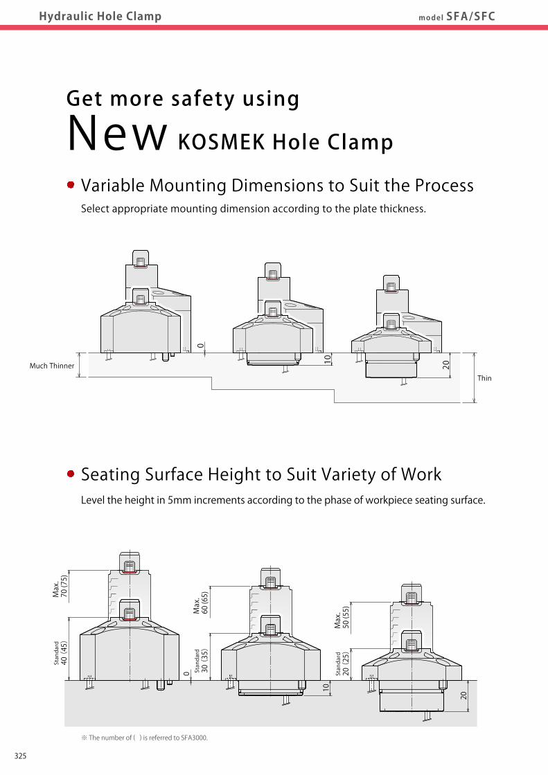
※ Max. operating pressure is 4MPa or 6MPa regarding to some of workpiece hole diameter.
at 4MPa:1.5kN
50%up
at 4MPa:1.0kN
at 4MPa:2.5kN
32%up
at 4MPa:1.9kN
at 4MPa:4.6kN
24%up
at 4MPa:3.7kN
Max:2.7kN Max:4.5kN Max:8.2kN
10 20
0
Thin
Much Thinner
Variable Mounting Dimensions to Suit the ProcessSelect appropriate mounting dimension according to the plate thickness.
Get more safety using
New KOSMEK Hole Clamp
Hole Diameter to Suit Variety of WorkIn order to suit different hole diameters and tolerances, hole diameters can be
specified in 0.5mm increments.
More Powerful Clamping ForceEnables wider range of operating pressure by having more powerful clamping force.
Seating Surface Height to Suit Variety of WorkLevel the height in 5mm increments according to the phase of workpiece seating surface.
Supply Hydraulic Pressure (MPa)
Clamping Force (kN)
Clamping Force (kN)
Clamping Force (kN)
Supply Hydraulic Pressure (MPa) Supply Hydraulic Pressure (MPa)
※ Max. operating pressure is 4MPa or 6MPa regarding to some of workpiece hole diameter.
※ The number of ( ) is referred to SFA3000.
325
Pneumatic Series
Hydraulic Series
Valve / CouplerHydraulic Unit
Cautions / Others
High-PowerSeries
Manual OperationAccessories
Hole Clamp
SFASFC
Link Clamp
LKALKCLKWLM/LJTMA-2TMA-1
Work Support
LDLCTNCTC
LLW
Air SensingLift Cylinder
Compact Cylinder
LLLLRLLUDPDRDSDT
Block Cylinder
DBADBC
Control Valve
BZLBZTBZX/JZG
Pallet Clamp
VSVT
Expansion Locating Pin
VFLVFMVFJVFK
FPFQ
Pull Stud Clamp
FVAFVDFVC
Centering Vise
DWA/DWB
CustomizedSpring Cylinder
Swing Clamp
LHALHCLHSLHWLT/LGTLA-2TLB-2TLA-1
SpecificationsPerformance Curve
IndexAction Description
Sample LayoutCircuit Reference
Model No. Indication
ExternalDimensionsmodel SFA/SFCHydraulic Hole Clamp
Hydraulic Hole ClampDigest
CautionsP.371
10
20
0
Max.
70 (75)
Max.
60 (65)
Max.
50 (55)
Standard
30 (35)
Standard
20 (25)
Standard
40 (45)
Workpiece Hole Diam. +0.7-0.3
12.5Model
SFA/SFC1000
SFA/SFC2000
SFA/SFC3000
SFA1000 SFA2000 SFA3000
Body Size - Type 1
Body Size - Type 2
Body Size - Type 3
6 6.5 7 7.5 8 8.5 9 9.5 10 10.5 11 11.5
Workpiece Hole Diameter (mm)
12 13 13.5 14 14.5 15 15.5 16
0
1
0.5
2
2.5
1.5
3
0 1 2 3 4 5 6 70
2
1
4
3
5
0
3
2
1
7
6
8
5
4
9
SFA1000
PreviousModel
0 1 2 3 4 5 6 7
SFA2000
PreviousModel
SFA3000
PreviousModel
0 1 2 3 4 5 6 7
※ Max. operating pressure is 4MPa or 6MPa regarding to some of workpiece hole diameter.
at 4MPa:1.5kN
50%up
at 4MPa:1.0kN
at 4MPa:2.5kN
32%up
at 4MPa:1.9kN
at 4MPa:4.6kN
24%up
at 4MPa:3.7kN
Max:2.7kN Max:4.5kN Max:8.2kN
10 20
0
Thin
Much Thinner
Variable Mounting Dimensions to Suit the ProcessSelect appropriate mounting dimension according to the plate thickness.
Get more safety using
New KOSMEK Hole Clamp
Hole Diameter to Suit Variety of WorkIn order to suit different hole diameters and tolerances, hole diameters can be
specified in 0.5mm increments.
More Powerful Clamping ForceEnables wider range of operating pressure by having more powerful clamping force.
Seating Surface Height to Suit Variety of WorkLevel the height in 5mm increments according to the phase of workpiece seating surface.
Supply Hydraulic Pressure (MPa)
Clamping Force (kN)
Clamping Force (kN)
Clamping Force (kN)
Supply Hydraulic Pressure (MPa) Supply Hydraulic Pressure (MPa)
※ Max. operating pressure is 4MPa or 6MPa regarding to some of workpiece hole diameter.
※ The number of ( ) is referred to SFA3000.
326
Pneumatic Series
Hydraulic Series
Valve / CouplerHydraulic Unit
Cautions / Others
High-PowerSeries
Manual OperationAccessories
Hole Clamp
SFASFC
Link Clamp
LKALKCLKWLM/LJTMA-2TMA-1
Work Support
LDLCTNCTC
LLW
Air SensingLift Cylinder
Compact Cylinder
LLLLRLLUDPDRDSDT
Block Cylinder
DBADBC
Control Valve
BZLBZTBZX/JZG
Pallet Clamp
VSVT
Expansion Locating Pin
VFLVFMVFJVFK
FPFQ
Pull Stud Clamp
FVAFVDFVC
Centering Vise
DWA/DWB
CustomizedSpring Cylinder
Swing Clamp
LHALHCLHSLHWLT/LGTLA-2TLB-2TLA-1
SpecificationsPerformance Curve
IndexAction Description
Sample LayoutCircuit Reference
Model No. Indication
ExternalDimensionsHydraulic Hole Clamp model SFA/SFC
Hydraulic Hole ClampDigest
CautionsP.371
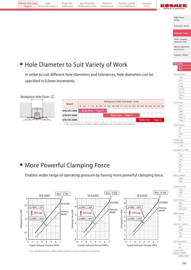
※ SFA/SFC1000 does not have the cap.
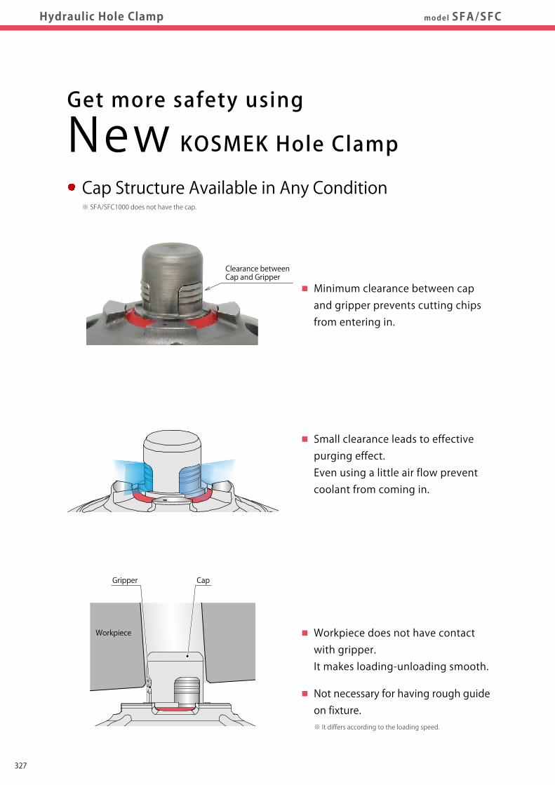
Workpiece does not have contact with gripper. It makes loading-unloading smooth.
Not necessary for having rough guideon fixture.
Minimum clearance between cap and gripper prevents cutting chipsfrom entering in.
Clearance betweenCap and Gripper
Small clearance leads to effective purging effect.Even using a little air flow preventcoolant from coming in.
Cap Structure Available in Any Condition Pursuing Good Design for Cutting ChipsHaving smaller seating surface and wide sweep area on the flange enables easy flow
of chips and reduction in coolant usage.
Secure Clamp Action Out of SightBuilt-in spring grips workpiece strongly and pulls it in.
There is no effect by the temperature and/or amount of oil.
※ It differs according to the loading speed.
Get more safety using
New KOSMEK Hole Clamp
Gripper expands. Pulls on to seating surface.
25゚
10゚
Seating Surface
※ part is inclined surface.
Workpiece
Gripper Cap
PressingNo Gap
Hydraulic Lock Port
Spring
Digging
327

Pneumatic Series
Hydraulic Series
Valve / CouplerHydraulic Unit
Cautions / Others
High-PowerSeries
Manual OperationAccessories
Hole Clamp
SFASFC
Link Clamp
LKALKCLKWLM/LJTMA-2TMA-1
Work Support
LDLCTNCTC
LLW
Air SensingLift Cylinder
Compact Cylinder
LLLLRLLUDPDRDSDT
Block Cylinder
DBADBC
Control Valve
BZLBZTBZX/JZG
Pallet Clamp
VSVT
Expansion Locating Pin
VFLVFMVFJVFK
FPFQ
Pull Stud Clamp
FVAFVDFVC
Centering Vise
DWA/DWB
CustomizedSpring Cylinder
Swing Clamp
LHALHCLHSLHWLT/LGTLA-2TLB-2TLA-1
SpecificationsPerformance Curve
IndexAction Description
Sample LayoutCircuit Reference
Model No. Indication
ExternalDimensionsHydraulic Hole Clamp model SFA/SFC
Hydraulic Hole ClampDigest
CautionsP.371
※ SFA/SFC1000 does not have the cap.
Workpiece does not have contact with gripper. It makes loading-unloading smooth.
Not necessary for having rough guideon fixture.
Minimum clearance between cap and gripper prevents cutting chipsfrom entering in.
Clearance betweenCap and Gripper
Small clearance leads to effective purging effect.Even using a little air flow preventcoolant from coming in.
Cap Structure Available in Any Condition Pursuing Good Design for Cutting ChipsHaving smaller seating surface and wide sweep area on the flange enables easy flow
of chips and reduction in coolant usage.
Secure Clamp Action Out of SightBuilt-in spring grips workpiece strongly and pulls it in.
There is no effect by the temperature and/or amount of oil.
※ It differs according to the loading speed.
Get more safety using
New KOSMEK Hole Clamp
Gripper expands. Pulls on to seating surface.
25゚
10゚
Seating Surface
※ part is inclined surface.
Workpiece
Gripper Cap
PressingNo Gap
Hydraulic Lock Port
Spring
Digging
328
Pneumatic Series
Hydraulic Series
Valve / CouplerHydraulic Unit
Cautions / Others
High-PowerSeries
Manual OperationAccessories
Hole Clamp
SFASFC
Link Clamp
LKALKCLKWLM/LJTMA-2TMA-1
Work Support
LDLCTNCTC
LLW
Air SensingLift Cylinder
Compact Cylinder
LLLLRLLUDPDRDSDT
Block Cylinder
DBADBC
Control Valve
BZLBZTBZX/JZG
Pallet Clamp
VSVT
Expansion Locating Pin
VFLVFMVFJVFK
FPFQ
Pull Stud Clamp
FVAFVDFVC
Centering Vise
DWA/DWB
CustomizedSpring Cylinder
Swing Clamp
LHALHCLHSLHWLT/LGTLA-2TLB-2TLA-1
SpecificationsPerformance Curve
IndexAction Description
Sample LayoutCircuit Reference
Model No. Indication
ExternalDimensionsHydraulic Hole Clamp model SFA/SFC
Hydraulic Hole ClampDigest
CautionsP.371
OFF OFF ON ON
Avoids interference with workpiece.
Avoids tool interferencefor backside machining.
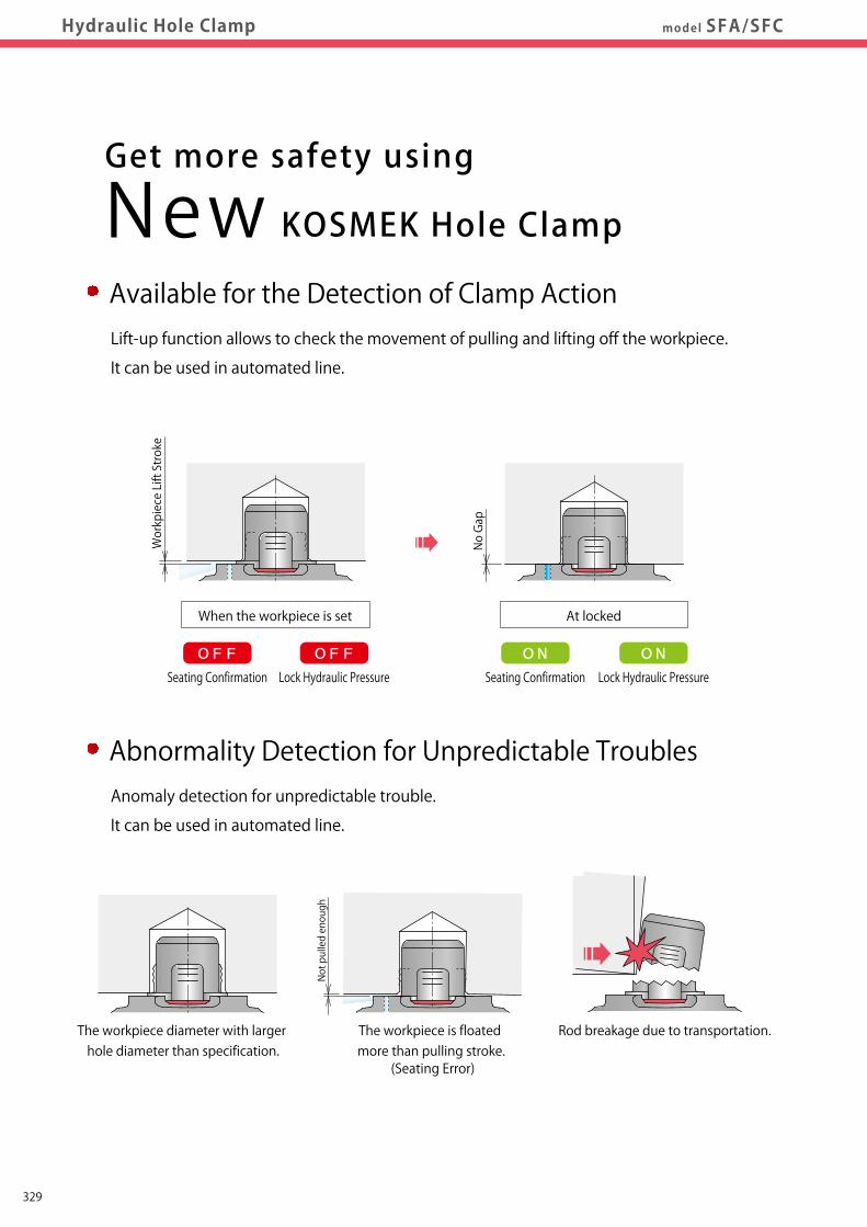
Offset ModelHydraulic Hole ClampAvailable for the Detection of Clamp ActionLift-up function allows to check the movement of pulling and lifting off the workpiece.
It can be used in automated line.
Get more safety using
New KOSMEK Hole Clamp
Abnormality Detection for Unpredictable TroublesAnomaly detection for unpredictable trouble.
It can be used in automated line.
Workpiece Lift Stroke
No Gap
Seating Confirmation
Not pulled enough
When the workpiece is set
Rod breakage due to transportation.The workpiece diameter with larger hole diameter than specification.
The workpiece is floated more than pulling stroke.
(Seating Error)
At locked
Lock Hydraulic Pressure Seating Confirmation Lock Hydraulic Pressure
Offset Model
The offset model allows for machining with no interference
of workpieces, fixtures, tools, etc. when there is interference
by using the standard SFA model.
Model SFC
329

Pneumatic Series
Hydraulic Series
Valve / CouplerHydraulic Unit
Cautions / Others
High-PowerSeries
Manual OperationAccessories
Hole Clamp
SFASFC
Link Clamp
LKALKCLKWLM/LJTMA-2TMA-1
Work Support
LDLCTNCTC
LLW
Air SensingLift Cylinder
Compact Cylinder
LLLLRLLUDPDRDSDT
Block Cylinder
DBADBC
Control Valve
BZLBZTBZX/JZG
Pallet Clamp
VSVT
Expansion Locating Pin
VFLVFMVFJVFK
FPFQ
Pull Stud Clamp
FVAFVDFVC
Centering Vise
DWA/DWB
CustomizedSpring Cylinder
Swing Clamp
LHALHCLHSLHWLT/LGTLA-2TLB-2TLA-1
SpecificationsPerformance Curve
IndexAction Description
Sample LayoutCircuit Reference
Model No. Indication
ExternalDimensionsHydraulic Hole Clamp model SFA/SFC
Hydraulic Hole ClampDigest
CautionsP.371
OFF OFF ON ON
Avoids interference with workpiece.
Avoids tool interferencefor backside machining.
Offset ModelHydraulic Hole ClampAvailable for the Detection of Clamp ActionLift-up function allows to check the movement of pulling and lifting off the workpiece.
It can be used in automated line.
Get more safety using
New KOSMEK Hole Clamp
Abnormality Detection for Unpredictable TroublesAnomaly detection for unpredictable trouble.
It can be used in automated line.
Workpiece Lift Stroke
No Gap
Seating Confirmation
Not pulled enough
When the workpiece is set
Rod breakage due to transportation.The workpiece diameter with larger hole diameter than specification.
The workpiece is floated more than pulling stroke.
(Seating Error)
At locked
Lock Hydraulic Pressure Seating Confirmation Lock Hydraulic Pressure
Offset Model
The offset model allows for machining with no interference
of workpieces, fixtures, tools, etc. when there is interference
by using the standard SFA model.
Model SFC
330

Pneumatic Series
Hydraulic Series
Valve / CouplerHydraulic Unit
Cautions / Others
High-PowerSeries
Manual OperationAccessories
Hole Clamp
SFASFC
Link Clamp
LKALKCLKWLM/LJTMA-2TMA-1
Work Support
LDLCTNCTC
LLW
Air SensingLift Cylinder
Compact Cylinder
LLLLRLLUDPDRDSDT
Block Cylinder
DBADBC
Control Valve
BZLBZTBZX/JZG
Pallet Clamp
VSVT
Expansion Locating Pin
VFLVFMVFJVFK
FPFQ
Pull Stud Clamp
FVAFVDFVC
Centering Vise
DWA/DWB
CustomizedSpring Cylinder
Swing Clamp
LHALHCLHSLHWLT/LGTLA-2TLB-2TLA-1
Hydraulic Hole ClampDigest P.323 CautionsSpecifications
Performance CurveIndex
Action DescriptionSample LayoutCircuit Reference
Model No. Indication
ExternalDimensionsmodel SFCHydraulic Hole Clamp Offset Model
Built-in Valve Function
Model SFC
Hydraulic Hole Clamp Offset Model
Low Pressure (1.5~7MPa)
Ability to Avoid Interferences
Index
Hydraulic Hole Clamp Digest
Action Description
Model No. Indication
Specifications
Performance Curve
External Dimensions
・ Body Size:1 Mounting Length 0mm (SFC1000-G0)
・ Body Size:1 Mounting Length 10/20mm (SFC1000-M□)
・ Body Size:2 Mounting Length 0mm (SFC2000-G0)
・ Body Size:2 Mounting Length 10/20mm (SFC2000-M□)
・ Body Size:3 Mounting Length 0mm (SFC3000-G0)
・ Body Size:3 Mounting Length 10/20mm (SFC3000-M□)
Sample Layout
Circuit Reference
Cautions
・ Notes for Hydraulic Hole Clamp
・ Cautions (Common) ・ Installation Notes ・ Hydraulic Fluid List ・ Notes on Hydraulic Cylinder Speed Control Circuit ・ Notes on Handling ・ Maintenance/Inspection ・ Warranty
P.323
P.352
P.353
P.354
P.355
P.357
P.359
P.361
P.363
P.365
P.367
P.369
P.370
P.371
P.1237
Taper Plane Part
Gripper
Hydraulic Release Port
② Gripping
③ Pressing
Trap Valve(Check Valve)
Rod
Action Description
①
Piston
②Shrinking
Workpiece Lift Surface
Seating SurfaceWorkpiece
Workpiece Lift Stroke
(0.2mm)
No Gap
Floating
Shrinking Band
Spring
Hydraulic Lock Port①
Bottom Surface Stopper
Discharged from the Trap Valve
Hydraulic Pressure Switch Seat Check Detection Release Pressure Lock Pressure (Air Sensor)
OFF
Released State
Locked State
①Hydraulic pressure is supplied to the release port.
↓
②The rod is lifted up and the gripper shrinks.
(Workpiece lift option:Gap is generated between
workpiece bottom surface and seating surface.)
①Hydraulic pressure is supplied to the lock port.
↓
②The rod descends and the gripper expands along the
taper plane. (Since the gripper is lifted by spring force,
it does not pull down.)
↓
③When pulling force exceeds the spring force,
pulling down force works after the gripper digs into
workpiece. Then, it presses workpiece onto seating surface.
(Clamping force = Pressing force onto seating surface.)
ON
ON
OFF
Hydraulic Pressure Switch Seat Check Detection Release Pressure Lock Pressure (Air Sensor)
OFF ON
Hydraulic Pressure Switch Seat Check Detection Release Pressure Lock Pressure (Air Sensor)
OFF ON OFF
Abnormality Detected State (Clamping without Workpiece)
The built-in check valve function and seating confirmation
air pressure detect abnormal condition as follows.
・ When clamping workpiece which has larger workpiece hole
diameter or clamping without workpiece (In this state the
gripper expands but the lifting spring does not have pulling
force so the workpiece lifting surface does not descend.)
・ When rod or gripper is broken.
・ If the piston is fully stroked when it has to stop at the bottom.
・ In the case workpiece is floated more than 1mm when setting it.
PAT.
351

Pneumatic Series
Hydraulic Series
Valve / CouplerHydraulic Unit
Cautions / Others
High-PowerSeries
Manual OperationAccessories
Hole Clamp
SFASFC
Link Clamp
LKALKCLKWLM/LJTMA-2TMA-1
Work Support
LDLCTNCTC
LLW
Air SensingLift Cylinder
Compact Cylinder
LLLLRLLUDPDRDSDT
Block Cylinder
DBADBC
Control Valve
BZLBZTBZX/JZG
Pallet Clamp
VSVT
Expansion Locating Pin
VFLVFMVFJVFK
FPFQ
Pull Stud Clamp
FVAFVDFVC
Centering Vise
DWA/DWB
CustomizedSpring Cylinder
Swing Clamp
LHALHCLHSLHWLT/LGTLA-2TLB-2TLA-1
Hydraulic Hole ClampDigest P.323 CautionsSpecifications
Performance CurveIndex
Action DescriptionSample LayoutCircuit Reference
Model No. Indication
ExternalDimensionsmodel SFCHydraulic Hole Clamp Offset Model
Built-in Valve Function
Model SFC
Hydraulic Hole Clamp Offset Model
Low Pressure (1.5~7MPa)
Ability to Avoid Interferences
Index
Hydraulic Hole Clamp Digest
Action Description
Model No. Indication
Specifications
Performance Curve
External Dimensions
・ Body Size:1 Mounting Length 0mm (SFC1000-G0)
・ Body Size:1 Mounting Length 10/20mm (SFC1000-M□)
・ Body Size:2 Mounting Length 0mm (SFC2000-G0)
・ Body Size:2 Mounting Length 10/20mm (SFC2000-M□)
・ Body Size:3 Mounting Length 0mm (SFC3000-G0)
・ Body Size:3 Mounting Length 10/20mm (SFC3000-M□)
Sample Layout
Circuit Reference
Cautions
・ Notes for Hydraulic Hole Clamp
・ Cautions (Common) ・ Installation Notes ・ Hydraulic Fluid List ・ Notes on Hydraulic Cylinder Speed Control Circuit ・ Notes on Handling ・ Maintenance/Inspection ・ Warranty
P.323
P.352
P.353
P.354
P.355
P.357
P.359
P.361
P.363
P.365
P.367
P.369
P.370
P.371
P.1237
Taper Plane Part
Gripper
Hydraulic Release Port
② Gripping
③ Pressing
Trap Valve(Check Valve)
Rod
Action Description
①
Piston
②Shrinking
Workpiece Lift Surface
Seating SurfaceWorkpiece
Workpiece Lift Stroke
(0.2mm)
No Gap
Floating
Shrinking Band
Spring
Hydraulic Lock Port①
Bottom Surface Stopper
Discharged from the Trap Valve
Hydraulic Pressure Switch Seat Check Detection Release Pressure Lock Pressure (Air Sensor)
OFF
Released State
Locked State
①Hydraulic pressure is supplied to the release port.
↓
②The rod is lifted up and the gripper shrinks.
(Workpiece lift option:Gap is generated between
workpiece bottom surface and seating surface.)
①Hydraulic pressure is supplied to the lock port.
↓
②The rod descends and the gripper expands along the
taper plane. (Since the gripper is lifted by spring force,
it does not pull down.)
↓
③When pulling force exceeds the spring force,
pulling down force works after the gripper digs into
workpiece. Then, it presses workpiece onto seating surface.
(Clamping force = Pressing force onto seating surface.)
ON
ON
OFF
Hydraulic Pressure Switch Seat Check Detection Release Pressure Lock Pressure (Air Sensor)
OFF ON
Hydraulic Pressure Switch Seat Check Detection Release Pressure Lock Pressure (Air Sensor)
OFF ON OFF
Abnormality Detected State (Clamping without Workpiece)
The built-in check valve function and seating confirmation
air pressure detect abnormal condition as follows.
・ When clamping workpiece which has larger workpiece hole
diameter or clamping without workpiece (In this state the
gripper expands but the lifting spring does not have pulling
force so the workpiece lifting surface does not descend.)
・ When rod or gripper is broken.
・ If the piston is fully stroked when it has to stop at the bottom.
・ In the case workpiece is floated more than 1mm when setting it.
PAT.
352

Pneumatic Series
Hydraulic Series
Valve / CouplerHydraulic Unit
Cautions / Others
High-PowerSeries
Manual OperationAccessories
Hole Clamp
SFASFC
Link Clamp
LKALKCLKWLM/LJTMA-2TMA-1
Work Support
LDLCTNCTC
LLW
Air SensingLift Cylinder
Compact Cylinder
LLLLRLLUDPDRDSDT
Block Cylinder
DBADBC
Control Valve
BZLBZTBZX/JZG
Pallet Clamp
VSVT
Expansion Locating Pin
VFLVFMVFJVFK
FPFQ
Pull Stud Clamp
FVAFVDFVC
Centering Vise
DWA/DWB
CustomizedSpring Cylinder
Swing Clamp
LHALHCLHSLHWLT/LGTLA-2TLB-2TLA-1
Hydraulic Hole ClampDigest P.323 CautionsSpecifications
Performance CurveIndex
Action DescriptionSample LayoutCircuit Reference
Model No. IndicationModel No. Indication
ExternalDimensionsmodel SFCHydraulic Hole Clamp Offset Model
Allowable RangeAllowable Range
3 Mounting Methods
G0 : Mounting Length 0mm
M1 : Mounting Length 10mm
M2 : Mounting Length 20mm
4 Workpiece Lifting Option
5 Workpiece Hole Diameter (Workpiece Hole Code)
1 Body Size
1 : Available in Diameters between φ6 and φ9mm (No Cap)
2 : Available in Diameters between φ9 and φ13mm (With Cap)
3 : Available in Diameters between φ13 and φ16mm (With Cap)
A : With Lift Function (Lift Function Option)
N : With No Lift Function
2
0 : Revision Number
Design No.
Model No. Indication
Workpiece Hole Code : Workpiece Hole Diameterφd
※ Workpiece hole diameter should be specified in 0.5mm increments from the allowable range in the table below.
+ 0.7- 0.3
Mounting Length 0mm Mounting Length 10mm Mounting Length 20mm
With Lift Function(Lift Function Option)
With No Lift Function
M2M1G0
NA
100 20
Workpiece Hole CodeWorkpiece Hole Diameter φd
No Cap
With Cap
SFC1000SFC2000SFC3000
(mm)
※ For workpiece hole diameter at ▲ part, maximum operating pressure is 4.0MPa. For workpiece hole diameter at ■ part, maximum operating pressure is 6.0MPa.
060 065 070 075 080 085 090 095 100 105 110 115 120 125 130 135 140 145 150 155 160 6 6.5 7 7.5 8 8.5 9 9.5 10 10.5 11 11.5 12 12.5 13 13.5 14 14.5 15 15.5 16
Lift Up
0.2mm
+ 0.7- 0.3
Allowable RangeAllowable Range▲▲ ▲▲ ■■ ■■▲▲ ▲▲ Allowable RangeAllowable Range
Workpiece Hole Diameterφd +0.7-0.3
No Gap
※ Please refer to specifications, performance curve and external dimensions for details.
21 3 4 65
SFC 2 00 0 - G0 N - 115 -
Note : 1. When using with expansion locating pins (model VFL, VFM, VFJ, VFK, VWM, VWK, VX), please choose N:With no lift function.
SFC2000/SFC3000 (With Cap)
Cap
SFC1000 (No Cap)
Specifications
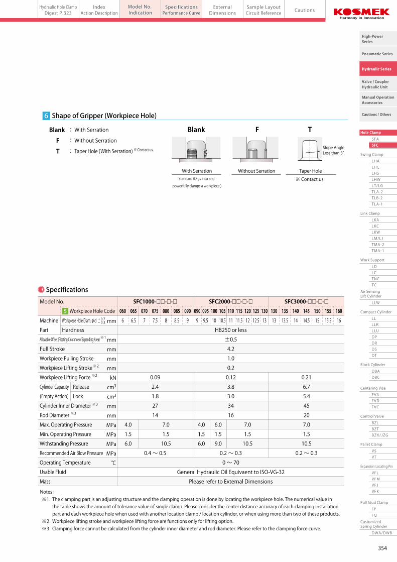
Notes : ※1. The clamping part is an adjusting structure and the clamping operation is done by locating the workpiece hole. The numerical value in the table shows the amount of tolerance value of single clamp. Please consider the center distance accuracy of each clamping installation part and each workpiece hole when used with another location clamp / location cylinder, or when using more than two of these products. ※2. Workpiece lifting stroke and workpiece lifting force are functions only for lifting option. ※3. Clamping force cannot be calculated from the cylinder inner diameter and rod diameter. Please refer to the clamping force curve.
Model No.
Workpiece Hole Code
Machine Workpiece Hole Diam.φd Part Hardness
Allowable Offset (Floating Clearance of Expanding Area)
Full Stroke
Workpiece Pulling Stroke
Workpiece Lifting Stroke
Workpiece Lifting Force
Cylinder Capacity Release
(Empty Action) Lock
Cylinder Inner Diameter Rod Diameter
Max. Operating Pressure
Min. Operating Pressure
Withstanding Pressure
Recommended Air Blow Pressure
Operating Temperature
Usable Fluid Mass
mm
mm
mm
mm
mm
kN
cm3
cm3
mm
mm
MPa
MPa
MPa
MPa
℃
SFC1000-□□-□-□ SFC2000-□□-□-□ SFC3000-□□-□-□
HB250 or less
±0.5
4.2
1.0
0.2
0.09 0.12 0.21
2.4 3.8 6.7
1.8 3.0 5.4
27 34 45
14 16 20
7.0
1.5
10.5
0.4 ~ 0.5 0.2 ~ 0.3 0.2 ~ 0.3
0 ~ 70
General Hydraulic Oil Equivaent to ISO-VG-32
Please refer to External Dimensions
4.0
1.5
6.0
7.0
1.5
10.5
7.0
1.5
10.5
4.0
1.5
6.0
6.0
1.5
9.0
060 065 070 075 080 085 090
※1
※2
※2
※3
※3
090 095 100 105 110 115 120 125 130 130 135 140 145 150 155 160
6 6.5 7 7.5 8 8.5 9 9 9.5 10 10.5 11 11.5 12 12.5 13 13 13.5 14 14.5 15 15.5 16+ 0.7- 0.3
5
7 Shape of Gripper (Workpiece Hole)
Blank : With Serration
F : Without Serration
T : Taper Hole (With Serration)Slope AngleLess than 3°
With SerrationStandard (Digs into and
powerfully clamps a workpiece.)
Taper Hole
※ Contact us.
※ Contact us.
Blank
Without Serration
F T
353
Pneumatic Series
Hydraulic Series
Valve / CouplerHydraulic Unit
Cautions / Others
High-PowerSeries
Manual OperationAccessories
Hole Clamp
SFASFC
Link Clamp
LKALKCLKWLM/LJTMA-2TMA-1
Work Support
LDLCTNCTC
LLW
Air SensingLift Cylinder
Compact Cylinder
LLLLRLLUDPDRDSDT
Block Cylinder
DBADBC
Control Valve
BZLBZTBZX/JZG
Pallet Clamp
VSVT
Expansion Locating Pin
VFLVFMVFJVFK
FPFQ
Pull Stud Clamp
FVAFVDFVC
Centering Vise
DWA/DWB
CustomizedSpring Cylinder
Swing Clamp
LHALHCLHSLHWLT/LGTLA-2TLB-2TLA-1
Hydraulic Hole ClampDigest P.323 CautionsSpecifications
Performance CurveIndex
Action DescriptionSample LayoutCircuit Reference
Model No. IndicationModel No. Indication
ExternalDimensionsmodel SFCHydraulic Hole Clamp Offset Model
Allowable RangeAllowable Range
3 Mounting Methods
G0 : Mounting Length 0mm
M1 : Mounting Length 10mm
M2 : Mounting Length 20mm
4 Workpiece Lifting Option
5 Workpiece Hole Diameter (Workpiece Hole Code)
1 Body Size
1 : Available in Diameters between φ6 and φ9mm (No Cap)
2 : Available in Diameters between φ9 and φ13mm (With Cap)
3 : Available in Diameters between φ13 and φ16mm (With Cap)
A : With Lift Function (Lift Function Option)
N : With No Lift Function
2
0 : Revision Number
Design No.
Model No. Indication
Workpiece Hole Code : Workpiece Hole Diameterφd
※ Workpiece hole diameter should be specified in 0.5mm increments from the allowable range in the table below.
+ 0.7- 0.3
Mounting Length 0mm Mounting Length 10mm Mounting Length 20mm
With Lift Function(Lift Function Option)
With No Lift Function
M2M1G0
NA
100 20
Workpiece Hole CodeWorkpiece Hole Diameter φd
No Cap
With Cap
SFC1000SFC2000SFC3000
(mm)
※ For workpiece hole diameter at ▲ part, maximum operating pressure is 4.0MPa. For workpiece hole diameter at ■ part, maximum operating pressure is 6.0MPa.
060 065 070 075 080 085 090 095 100 105 110 115 120 125 130 135 140 145 150 155 160 6 6.5 7 7.5 8 8.5 9 9.5 10 10.5 11 11.5 12 12.5 13 13.5 14 14.5 15 15.5 16
Lift Up
0.2mm
+ 0.7- 0.3
Allowable RangeAllowable Range▲▲ ▲▲ ■■ ■■▲▲ ▲▲ Allowable RangeAllowable Range
Workpiece Hole Diameterφd +0.7-0.3
No Gap
※ Please refer to specifications, performance curve and external dimensions for details.
21 3 4 65
SFC 2 00 0 - G0 N - 115 -
Note : 1. When using with expansion locating pins (model VFL, VFM, VFJ, VFK, VWM, VWK, VX), please choose N:With no lift function.
SFC2000/SFC3000 (With Cap)
Cap
SFC1000 (No Cap)
Specifications
Notes : ※1. The clamping part is an adjusting structure and the clamping operation is done by locating the workpiece hole. The numerical value in the table shows the amount of tolerance value of single clamp. Please consider the center distance accuracy of each clamping installation part and each workpiece hole when used with another location clamp / location cylinder, or when using more than two of these products. ※2. Workpiece lifting stroke and workpiece lifting force are functions only for lifting option. ※3. Clamping force cannot be calculated from the cylinder inner diameter and rod diameter. Please refer to the clamping force curve.
Model No.
Workpiece Hole Code
Machine Workpiece Hole Diam.φd Part Hardness
Allowable Offset (Floating Clearance of Expanding Area)
Full Stroke
Workpiece Pulling Stroke
Workpiece Lifting Stroke
Workpiece Lifting Force
Cylinder Capacity Release
(Empty Action) Lock
Cylinder Inner Diameter Rod Diameter
Max. Operating Pressure
Min. Operating Pressure
Withstanding Pressure
Recommended Air Blow Pressure
Operating Temperature
Usable Fluid Mass
mm
mm
mm
mm
mm
kN
cm3
cm3
mm
mm
MPa
MPa
MPa
MPa
℃
SFC1000-□□-□-□ SFC2000-□□-□-□ SFC3000-□□-□-□
HB250 or less
±0.5
4.2
1.0
0.2
0.09 0.12 0.21
2.4 3.8 6.7
1.8 3.0 5.4
27 34 45
14 16 20
7.0
1.5
10.5
0.4 ~ 0.5 0.2 ~ 0.3 0.2 ~ 0.3
0 ~ 70
General Hydraulic Oil Equivaent to ISO-VG-32
Please refer to External Dimensions
4.0
1.5
6.0
7.0
1.5
10.5
7.0
1.5
10.5
4.0
1.5
6.0
6.0
1.5
9.0
060 065 070 075 080 085 090
※1
※2
※2
※3
※3
090 095 100 105 110 115 120 125 130 130 135 140 145 150 155 160
6 6.5 7 7.5 8 8.5 9 9 9.5 10 10.5 11 11.5 12 12.5 13 13 13.5 14 14.5 15 15.5 16+ 0.7- 0.3
5
6 Shape of Gripper (Workpiece Hole)
Blank : With Serration
F : Without Serration
T : Taper Hole (With Serration)Slope AngleLess than 3°
With SerrationStandard (Digs into and
powerfully clamps a workpiece.)
Taper Hole
※ Contact us.
※ Contact us.
Blank
Without Serration
F T
354
Pneumatic Series
Hydraulic Series
Valve / CouplerHydraulic Unit
Cautions / Others
High-PowerSeries
Manual OperationAccessories
Hole Clamp
SFASFC
Link Clamp
LKALKCLKWLM/LJTMA-2TMA-1
Work Support
LDLCTNCTC
LLW
Air SensingLift Cylinder
Compact Cylinder
LLLLRLLUDPDRDSDT
Block Cylinder
DBADBC
Control Valve
BZLBZTBZX/JZG
Pallet Clamp
VSVT
Expansion Locating Pin
VFLVFMVFJVFK
FPFQ
Pull Stud Clamp
FVAFVDFVC
Centering Vise
DWA/DWB
CustomizedSpring Cylinder
Swing Clamp
LHALHCLHSLHWLT/LGTLA-2TLB-2TLA-1
Hydraulic Hole ClampDigest P.323 CautionsSpecifications
Performance CurveIndex
Action DescriptionSample LayoutCircuit Reference
Model No. Indication
ExternalDimensionsmodel SFCHydraulic Hole Clamp Offset Model
MEMO
SFC1000 / SFC1000-T
SFC1000-FSFC2000-F
SFC3000-F
SFC2000 / SFC2000-T
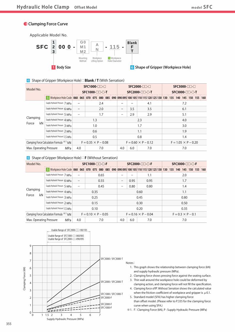
SFC3000 / SFC3000-TNotes: 1. This graph shows the relationship between clamping force (kN) and supply hydraulic pressure (MPa). 2. Clamping force shows pressing force against the seating surface. 3. Thin wall around the workpiece hole could be deformed by clamping action, and clamping force will not fill the specification. 4. Clamping force of F:Without Serration shows the calculated value when the friction coefficient of workpiece and gripper is μ0.1. 5. Standard model (SFA) has higher clamping force than offset model. (Please refer to P.335 for the clamping force curve when using SFA.) ※1. F: Clamping Force (kN), P : Supply Hydraulic Pressure (MPa)
BlankFT
Applicable Model No.
SFC 00 0 - - 115 -AN
WorkpieceLifting Option
G0M1M2MountingMethod
1 Body Size
123
6 Shape of Gripper (Workpiece Hole)
Model No.
Workpiece Hole Code
Clamping Force Calculation Formula
Max. Operating Pressure
Supply Hydraulic Pressure 7 MPaSupply Hydraulic Pressure 6 MPaSupply Hydraulic Pressure 5 MPaSupply Hydraulic Pressure 4 MPaSupply Hydraulic Pressure 3 MPaSupply Hydraulic Pressure 2 MPaSupply Hydraulic Pressure 1.5 MPa
kN
MPa
SFC1000-□□-□ SFC2000-□□-□ SFC3000-□□-□
SFC1000-□□-□-T SFC2000-□□-□-T SFC3000-□□-□-T
7.2
6.1
5.1
1.3 2.3 4.0
1.0 1.7 3.0
0.6 1.1 1.9
0.5 0.8 1.4
F = 0.35 × P - 0.08 F = 0.60 × P - 0.12 F = 1.05 × P - 0.20
7.0
※1
060 065 070 075 080 085 090 090 095 100 105 110 115 120 125 130 130 135 140 145 150 155 1605
-
-
-
4.0
-
-
-
4.0
-
3.5
2.9
6.0
4.1
3.5
2.9
7.0
2.4
2.0
1.7
7.0
Shape of Gripper (Workpiece Hole):Blank / T (With Serration)6
Model No.
Workpiece Hole Code
Clamping Force Calculation Formula
Max. Operating Pressure
Supply Hydraulic Pressure 7 MPaSupply Hydraulic Pressure 6 MPaSupply Hydraulic Pressure 5 MPaSupply Hydraulic Pressure 4 MPaSupply Hydraulic Pressure 3 MPaSupply Hydraulic Pressure 2 MPaSupply Hydraulic Pressure 1.5 MPa
kN
MPa
SFC1000-□□-□-F SFC2000-□□-□-F SFC3000-□□-□-F
2.0
1.7
1.4
0.35 0.60 1.1
0.25 0.45 0.80
0.15 0.30 0.50
0.10 0.20 0.35
F = 0.10 × P - 0.05 F = 0.16 × P - 0.04 F = 0.3 × P - 0.1
7.0
※1
060 065 070 075 080 085 090 090 095 100 105 110 115 120 125 130 130 135 140 145 150 155 1605
-
-
-
4.0
-
-
-
4.0
-
0.95
0.80
6.0
1.1
0.95
0.80
7.0
0.65
0.55
0.45
7.0
Shape of Gripper (Workpiece Hole):F (Without Serration)6
0
1
Clamping Force (kN)
2
3
4
5
6
7
8
9
0 1 1.5 2 3 4 5 6 7Supply Hydraulic Pressure (MPa)
Usable Range of SFC2000-□□-090/095Usable Range of SFC1000-□□-060/065
Usable Range of SFC2000-□□-100/105
Clamping Force Curve
Clamping
Force kN
Clamping
Force kN
WorkpieceHole Diameter 5
355

Pneumatic Series
Hydraulic Series
Valve / CouplerHydraulic Unit
Cautions / Others
High-PowerSeries
Manual OperationAccessories
Hole Clamp
SFASFC
Link Clamp
LKALKCLKWLM/LJTMA-2TMA-1
Work Support
LDLCTNCTC
LLW
Air SensingLift Cylinder
Compact Cylinder
LLLLRLLUDPDRDSDT
Block Cylinder
DBADBC
Control Valve
BZLBZTBZX/JZG
Pallet Clamp
VSVT
Expansion Locating Pin
VFLVFMVFJVFK
FPFQ
Pull Stud Clamp
FVAFVDFVC
Centering Vise
DWA/DWB
CustomizedSpring Cylinder
Swing Clamp
LHALHCLHSLHWLT/LGTLA-2TLB-2TLA-1
Hydraulic Hole ClampDigest P.323 CautionsSpecifications
Performance CurveIndex
Action DescriptionSample LayoutCircuit Reference
Model No. Indication
ExternalDimensionsmodel SFCHydraulic Hole Clamp Offset Model
MEMO
SFC1000 / SFC1000-T
SFC1000-FSFC2000-F
SFC3000-F
SFC2000 / SFC2000-T
SFC3000 / SFC3000-TNotes: 1. This graph shows the relationship between clamping force (kN) and supply hydraulic pressure (MPa). 2. Clamping force shows pressing force against the seating surface. 3. Thin wall around the workpiece hole could be deformed by clamping action, and clamping force will not fill the specification. 4. Clamping force of F:Without Serration shows the calculated value when the friction coefficient of workpiece and gripper is μ0.1. 5. Standard model (SFA) has higher clamping force than offset model. (Please refer to P.335 for the clamping force curve when using SFA.) ※1. F: Clamping Force (kN), P : Supply Hydraulic Pressure (MPa)
BlankFT
Applicable Model No.
SFC 00 0 - - 115 -AN
WorkpieceLifting Option
G0M1M2MountingMethod
1 Body Size
123
6 Shape of Gripper (Workpiece Hole)
Model No.
Workpiece Hole Code
Clamping Force Calculation Formula
Max. Operating Pressure
Supply Hydraulic Pressure 7 MPaSupply Hydraulic Pressure 6 MPaSupply Hydraulic Pressure 5 MPaSupply Hydraulic Pressure 4 MPaSupply Hydraulic Pressure 3 MPaSupply Hydraulic Pressure 2 MPaSupply Hydraulic Pressure 1.5 MPa
kN
MPa
SFC1000-□□-□ SFC2000-□□-□ SFC3000-□□-□
SFC1000-□□-□-T SFC2000-□□-□-T SFC3000-□□-□-T
7.2
6.1
5.1
1.3 2.3 4.0
1.0 1.7 3.0
0.6 1.1 1.9
0.5 0.8 1.4
F = 0.35 × P - 0.08 F = 0.60 × P - 0.12 F = 1.05 × P - 0.20
7.0
※1
060 065 070 075 080 085 090 090 095 100 105 110 115 120 125 130 130 135 140 145 150 155 1605
-
-
-
4.0
-
-
-
4.0
-
3.5
2.9
6.0
4.1
3.5
2.9
7.0
2.4
2.0
1.7
7.0
Shape of Gripper (Workpiece Hole):Blank / T (With Serration)6
Model No.
Workpiece Hole Code
Clamping Force Calculation Formula
Max. Operating Pressure
Supply Hydraulic Pressure 7 MPaSupply Hydraulic Pressure 6 MPaSupply Hydraulic Pressure 5 MPaSupply Hydraulic Pressure 4 MPaSupply Hydraulic Pressure 3 MPaSupply Hydraulic Pressure 2 MPaSupply Hydraulic Pressure 1.5 MPa
kN
MPa
SFC1000-□□-□-F SFC2000-□□-□-F SFC3000-□□-□-F
2.0
1.7
1.4
0.35 0.60 1.1
0.25 0.45 0.80
0.15 0.30 0.50
0.10 0.20 0.35
F = 0.10 × P - 0.05 F = 0.16 × P - 0.04 F = 0.3 × P - 0.1
7.0
※1
060 065 070 075 080 085 090 090 095 100 105 110 115 120 125 130 130 135 140 145 150 155 1605
-
-
-
4.0
-
-
-
4.0
-
0.95
0.80
6.0
1.1
0.95
0.80
7.0
0.65
0.55
0.45
7.0
Shape of Gripper (Workpiece Hole):F (Without Serration)6
0
1
Clamping Force (kN)
2
3
4
5
6
7
8
9
0 1 1.5 2 3 4 5 6 7Supply Hydraulic Pressure (MPa)
Usable Range of SFC2000-□□-090/095Usable Range of SFC1000-□□-060/065
Usable Range of SFC2000-□□-100/105
Clamping Force Curve
Clamping
Force kN
Clamping
Force kN
WorkpieceHole Diameter 5
356

Pneumatic Series
Hydraulic Series
Valve / CouplerHydraulic Unit
Cautions / Others
High-PowerSeries
Manual OperationAccessories
Hole Clamp
SFASFC
Link Clamp
LKALKCLKWLM/LJTMA-2TMA-1
Work Support
LDLCTNCTC
LLW
Air SensingLift Cylinder
Compact Cylinder
LLLLRLLUDPDRDSDT
Block Cylinder
DBADBC
Control Valve
BZLBZTBZX/JZG
Pallet Clamp
VSVT
Expansion Locating Pin
VFLVFMVFJVFK
FPFQ
Pull Stud Clamp
FVAFVDFVC
Centering Vise
DWA/DWB
CustomizedSpring Cylinder
Swing Clamp
LHALHCLHSLHWLT/LGTLA-2TLB-2TLA-1
Hydraulic Hole ClampDigest P.323 CautionsSpecifications
Performance CurveIndex
Action DescriptionSample LayoutCircuit Reference
Model No. Indication
ExternalDimensionsExternalDimensionsmodel SFC1000-G0Hydraulic Hole Clamp Offset Model
External Dimensions※This drawing shows the released state of SFC1000-G0A-□.
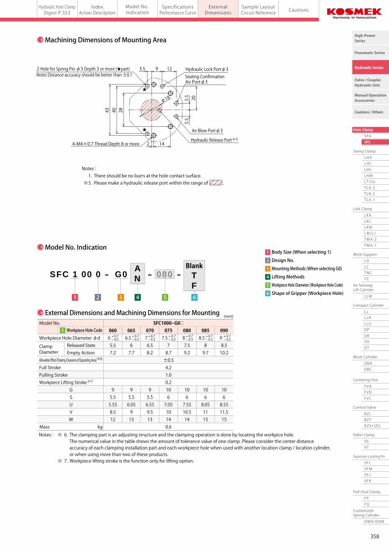
Machining Dimensions of Mounting Area
Notes: ※1. The workpiece must be resting on all seating surfaces when clamping. If this is not done the workpiece can be deformed by the clamping force. ※2. The port name is marked on the product surface. (HYD:Hydraulic Lock Port, FC:Seat Confirmation Port, BLOW:Air Blow Port) Continuously supply air pressure to the air blow port and the seating confirmation port. ※3. The numerical value is only for the workpiece lifting option.
Model No. Indication
4 Lifting Methods
3 Mounting Methods (When selecting G0)
1 Body Size (When selecting 1)
2 Design No.
6 Shape of Gripper (Workpiece Hole)
5 Workpiece Hole Diameter (Workpiece Hole Code)
※ Expanding Area Detail
At Full Stroke(Empty Action)
Clamp Diameter(At Released)
(Clearance from seating surface when releasing) Workpiece Lifting Stroke ※3
0.2
Clamp Diameter(Empty Action)
S
Clamp Area
φV※3
G (G)
Full Stroke
4.2
External Dimensions and Machining Dimensions for Mounting
Notes: ※ 6. The clamping part is an adjusting structure and the clamping operation is done by locating the workpice hole. The numerical value in the table shows the amount of tolerance value of one clamp. Please consider the center distance accuracy of each clamping installation part and each workpiece hole when used with another location clamp / location cylinder, or when using more than two of these products. ※ 7. Workpiece lifting stroke is the function only for lifting option.
+ 0.7- 0.3
+ 0.7- 0.3
+ 0.7- 0.3
+ 0.7- 0.3
+ 0.7- 0.3
+ 0.7- 0.3
+ 0.7- 0.3
※6
※7
(mm)
Model No.
Workpiece Hole Diameter φd Released State Clamp Diameter Empty Action Allowable Offset (Floating Clearance of Expanding Area) Full Stroke Pulling Stroke Workpiece Lifting Stroke G S U V W Mass kg
SFC1000-G0□ 060 065 070 075 080 085 090 6 6.5 7 7.5 8 8.5 9 5.5 6 6.5 7 7.5 8 8.5 7.2 7.7 8.2 8.7 9.2 9.7 10.2 ±0.5 4.2 1.0 0.2 9 9 9 10 10 10 10 5.5 5.5 5.5 6 6 6 6 5.55 6.05 6.55 7.05 7.55 8.05 8.55 8.5 9 9.5 10 10.5 11 11.5 12 13 13 14 14 15 15 0.6
5 Workpiece Hole Code
Released State
Notes: 1. Thin wall around the workpiece hole could be deformed by clamping action, and clamping force will not fill the specification. Please make sure to test the clamping function before using and adjust to the appropriate supply of pressure. ※4. When the clamp head is sticking above the Y surface of the workpiece, please make sure there is no interference with the clamp cylinders during machining.
S or more
Through Hole Taper Hole
C0.5 or less C0.5 or lessG+0.5 or more Y Surface※4
※ Contact us for details.
Workpiece (Pallet) Hole Dimensions
Slope Angle(3° or less)
WorkpieceHole Diameter
φd
WorkpieceHole Diameter
φd
Notes : 1. There should be no burrs at the hole contact surface. ※5. Please make a hydraulic release port within the range of .
3 4
AN
21 5
SFC 1 00 0 - G0 080- -
6
TF
Blank
★
★
φ18
43 2840
2 14
5.5
5.5
20
9 123.57.5
3
φ18
40
1293.52-φ3 Spring Pin (Included)
5.5
5.5 20
42.1
φ22
G
16
φU
7.6
Seating SurfaceOuter Diameterφ21
5.5
φ54
Seating SurfaceInner DiameterφW 45゚
44.5
10.5 8 262 14
Offset Volume4328
Trap Valve
4-Mounting Bolt (Included)M4×0.7×45
3-O-ring (Included) AS568-006(90°)
Seating Surface※1
Gripper (4 Grippers 90° Distance)(The gripper direction is optional.)
65 ±0.005
1-O-ring (Included) AS568-025(90°)
Air Blow Port ※2
Seating ConfirmationAir Port
※2
Hydraulic Lock Port ※2
Air Blow Portφ3
Hydraulic Lock Portφ3
4-M4×0.7 Thread Depth 8 or more
2-Hole for Spring Pin φ3 Depth 3 or more (★part)Note) Distance accuracy should be better than ±0.1
Hydraulic Release Port※5
15゚R1
Air Blow-Out Hole for Seating Confirmation φ1
Seating ConfirmationAir Portφ3
(Workpiece Lifting Surface)
Blind Hole
357
Pneumatic Series
Hydraulic Series
Valve / CouplerHydraulic Unit
Cautions / Others
High-PowerSeries
Manual OperationAccessories
Hole Clamp
SFASFC
Link Clamp
LKALKCLKWLM/LJTMA-2TMA-1
Work Support
LDLCTNCTC
LLW
Air SensingLift Cylinder
Compact Cylinder
LLLLRLLUDPDRDSDT
Block Cylinder
DBADBC
Control Valve
BZLBZTBZX/JZG
Pallet Clamp
VSVT
Expansion Locating Pin
VFLVFMVFJVFK
FPFQ
Pull Stud Clamp
FVAFVDFVC
Centering Vise
DWA/DWB
CustomizedSpring Cylinder
Swing Clamp
LHALHCLHSLHWLT/LGTLA-2TLB-2TLA-1
Hydraulic Hole ClampDigest P.323 CautionsSpecifications
Performance CurveIndex
Action DescriptionSample LayoutCircuit Reference
Model No. Indication
ExternalDimensionsExternalDimensionsmodel SFC1000-G0Hydraulic Hole Clamp Offset Model
External Dimensions※This drawing shows the released state of SFC1000-G0A-□.
Machining Dimensions of Mounting Area
Notes: ※1. The workpiece must be resting on all seating surfaces when clamping. If this is not done the workpiece can be deformed by the clamping force. ※2. The port name is marked on the product surface. (HYD:Hydraulic Lock Port, FC:Seat Confirmation Port, BLOW:Air Blow Port) Continuously supply air pressure to the air blow port and the seating confirmation port. ※3. The numerical value is only for the workpiece lifting option.
Model No. Indication
4 Lifting Methods
3 Mounting Methods (When selecting G0)
1 Body Size (When selecting 1)
2 Design No.
6 Shape of Gripper (Workpiece Hole)
5 Workpiece Hole Diameter (Workpiece Hole Code)
※ Expanding Area Detail
At Full Stroke(Empty Action)
Clamp Diameter(At Released)
(Clearance from seating surface when releasing) Workpiece Lifting Stroke ※3
0.2
Clamp Diameter(Empty Action)
S
Clamp Area
φV※3
G (G)
Full Stroke
4.2
External Dimensions and Machining Dimensions for Mounting
Notes: ※ 6. The clamping part is an adjusting structure and the clamping operation is done by locating the workpice hole. The numerical value in the table shows the amount of tolerance value of one clamp. Please consider the center distance accuracy of each clamping installation part and each workpiece hole when used with another location clamp / location cylinder, or when using more than two of these products. ※ 7. Workpiece lifting stroke is the function only for lifting option.
+ 0.7- 0.3
+ 0.7- 0.3
+ 0.7- 0.3
+ 0.7- 0.3
+ 0.7- 0.3
+ 0.7- 0.3
+ 0.7- 0.3
※6
※7
(mm)
Model No.
Workpiece Hole Diameter φd Released State Clamp Diameter Empty Action Allowable Offset (Floating Clearance of Expanding Area) Full Stroke Pulling Stroke Workpiece Lifting Stroke G S U V W Mass kg
SFC1000-G0□ 060 065 070 075 080 085 090 6 6.5 7 7.5 8 8.5 9 5.5 6 6.5 7 7.5 8 8.5 7.2 7.7 8.2 8.7 9.2 9.7 10.2 ±0.5 4.2 1.0 0.2 9 9 9 10 10 10 10 5.5 5.5 5.5 6 6 6 6 5.55 6.05 6.55 7.05 7.55 8.05 8.55 8.5 9 9.5 10 10.5 11 11.5 12 13 13 14 14 15 15 0.6
5 Workpiece Hole Code
Released State
Notes: 1. Thin wall around the workpiece hole could be deformed by clamping action, and clamping force will not fill the specification. Please make sure to test the clamping function before using and adjust to the appropriate supply of pressure. ※4. When the clamp head is sticking above the Y surface of the workpiece, please make sure there is no interference with the clamp cylinders during machining.
S or more
Through Hole Taper Hole
C0.5 or less C0.5 or lessG+0.5 or more Y Surface※4
※ Contact us for details.
Workpiece (Pallet) Hole Dimensions
Slope Angle(3° or less)
WorkpieceHole Diameter
φd
WorkpieceHole Diameter
φd
Notes : 1. There should be no burrs at the hole contact surface. ※5. Please make a hydraulic release port within the range of .
3 4
AN
21 5
SFC 1 00 0 - G0 080- -
6
TF
Blank
★
★
φ18
43 2840
2 14
5.5
5.5
20
9 123.5
7.5
3
φ18
40
1293.52-φ3 Spring Pin (Included)
5.5
5.5 20
42.1
φ22
G
16
φU
7.6
Seating SurfaceOuter Diameterφ21
5.5
φ54
Seating SurfaceInner DiameterφW 45゚
44.5
10.5 8 262 14
Offset Volume
4328
Trap Valve
4-Mounting Bolt (Included)M4×0.7×45
3-O-ring (Included) AS568-006(90°)
Seating Surface※1
Gripper (4 Grippers 90° Distance)(The gripper direction is optional.)
65 ±0.005
1-O-ring (Included) AS568-025(90°)
Air Blow Port ※2
Seating ConfirmationAir Port
※2
Hydraulic Lock Port ※2
Air Blow Portφ3
Hydraulic Lock Portφ3
4-M4×0.7 Thread Depth 8 or more
2-Hole for Spring Pin φ3 Depth 3 or more (★part)Note) Distance accuracy should be better than ±0.1
Hydraulic Release Port※5
15゚R1
Air Blow-Out Hole for Seating Confirmation φ1
Seating ConfirmationAir Portφ3
(Workpiece Lifting Surface)
Blind Hole
358
Pneumatic Series
Hydraulic Series
Valve / CouplerHydraulic Unit
Cautions / Others
High-PowerSeries
Manual OperationAccessories
Hole Clamp
SFASFC
Link Clamp
LKALKCLKWLM/LJTMA-2TMA-1
Work Support
LDLCTNCTC
LLW
Air SensingLift Cylinder
Compact Cylinder
LLLLRLLUDPDRDSDT
Block Cylinder
DBADBC
Control Valve
BZLBZTBZX/JZG
Pallet Clamp
VSVT
Expansion Locating Pin
VFLVFMVFJVFK
FPFQ
Pull Stud Clamp
FVAFVDFVC
Centering Vise
DWA/DWB
CustomizedSpring Cylinder
Swing Clamp
LHALHCLHSLHWLT/LGTLA-2TLB-2TLA-1
Hydraulic Hole ClampDigest P.323 CautionsSpecifications
Performance CurveIndex
Action DescriptionSample LayoutCircuit Reference
Model No. Indication
ExternalDimensionsExternalDimensionsmodel SFC1000-M□Hydraulic Hole Clamp Offset Model
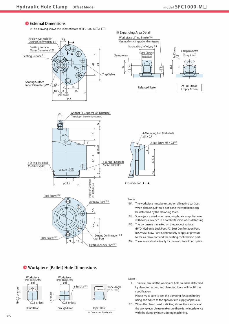
External Dimensions※This drawing shows the released state of SFC1000-M□A-□.
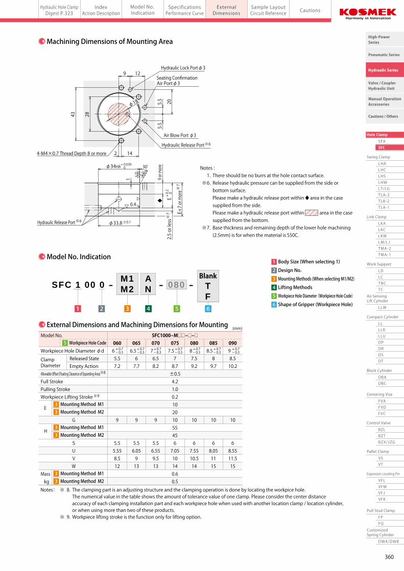
Machining Dimensions of Mounting Area
※ Expanding Area Detail
At Full Stroke(Empty Action)
Clamp Diameter
(Clearance from seating surface when releasing) ※4
0.2
Clamp Diameter(Empty Action)
S
Clamp Area
φV※4
G (G)
Full Stroke
4.2
Notes: ※1. The workpiece must be resting on all seating surfaces when clamping. If this is not done the workpiece can be deformed by the clamping force. ※2. Screw jack is used when removing hole clamp. Remove with torque wrench in a parallel fashion when detaching. ※3. The port name is marked on the product surface. (HYD:Hydraulic Lock Port, FC:Seat Confirmation Port, BLOW:Air Blow Port) Continuously supply air pressure to the air blow port and the seating confirmation port. ※4. The numerical value is only for the workpiece lifting option.
Model No. Indication
4 Lifting Methods
3 Mounting Methods (When selecting M1/M2)
1 Body Size (When selecting 1)
2 Design No.
6 Shape of Gripper (Workpiece Hole)
5 Workpiece Hole Diameter (Workpiece Hole Code)
※6
Released State
(Released State)
Workpiece Lifting Stroke
(Workpiece Lifting Surface)
Notes: 1. Thin wall around the workpiece hole could be deformed by clamping action, and clamping force will not fill the specification. Please make sure to test the clamping function before using and adjust to the appropriate supply of pressure. ※5. When the clamp head is sticking above the Y surface of the workpiece, please make sure there is no interference with the clamp cylinders during machining.
S or more
Through Hole Taper Hole
C0.5 or less C0.5 or lessG+0.5 or more Y Surface※5
※ Contact us for details.
Workpiece (Pallet) Hole Dimensions
Slope Angle(3° or less)
WorkpieceHole Diameter
φd
WorkpieceHole Diameter
φd
Notes : 1. There should be no burrs at the hole contact surface. ※6. Release hydraulic pressure can be supplied from the side or bottom surface. Please make a hydraulic release port within ◆ area in the case supplied from the side. Please make a hydraulic release port within area in the case supplied from the bottom. ※7. Base thickness and remaining depth of the lower hole machining (2.5mm) is for when the material is S50C.
3
M1M2
4
AN
21 5
SFC 1 00 0 - 080- -
6
TF
Blank
External Dimensions and Machining Dimensions for Mounting
Notes: ※ 8. The clamping part is an adjusting structure and the clamping operation is done by locating the workpice hole. The numerical value in the table shows the amount of tolerance value of one clamp. Please consider the center distance accuracy of each clamping installation part and each workpiece hole when used with another location clamp / location cylinder, or when using more than two of these products. ※ 9. Workpiece lifting stroke is the function only for lifting option.
+ 0.7- 0.3
+ 0.7- 0.3
+ 0.7- 0.3
+ 0.7- 0.3
+ 0.7- 0.3
+ 0.7- 0.3
+ 0.7- 0.3
※8
※9
(mm)
Model No.
Workpiece Hole Diameter φd Released State Clamp Diameter Empty Action Allowable Offset (Floating Clearance of Expanding Area) Full Stroke Pulling Stroke Workpiece Lifting Stroke
G
S U V W Mass kg
SFC1000-M□□-□-□ 060 065 070 075 080 085 090 6 6.5 7 7.5 8 8.5 9 5.5 6 6.5 7 7.5 8 8.5 7.2 7.7 8.2 8.7 9.2 9.7 10.2 ±0.5 4.2 1.0 0.2 10 20 9 9 9 10 10 10 10 55 45 5.5 5.5 5.5 6 6 6 6 5.55 6.05 6.55 7.05 7.55 8.05 8.55 8.5 9 9.5 10 10.5 11 11.5 12 13 13 14 14 15 15 0.6 0.5
5 Workpiece Hole Code
E
H
3 Mounting Method M13 Mounting Method M2
3 Mounting Method M13 Mounting Method M2
3 Mounting Method M13 Mounting Method M2
Blind Hole
Cross Section ★-★
4-Mounting Bolt (Included)M4×0.7
- 0.025- 0.064φ34f8
Projection Dimension
at Full Stroke 0.5
φ18
129
5.5
5.5 20
42.1
- E
φ22
G
16
φU
7.6
Seating SurfaceOuter Diameterφ21
5.5
φ54
Seating SurfaceInner DiameterφW 45゚
44.5
10.5 8 262 14
Offset Volume4328
Trap Valve
Seating Surface※1
H ±0.005
E
1-O-ring (Included) AS568-025(90°)
Air Blow Port ※3
φ33.5
3-O-ring (Included) AS568-006(90°)
(Jack Screw)※2
φ18
43 28
2 14
9 12
Air Blow Port φ3
Hydraulic Lock Portφ3
4-M4×0.7 Thread Depth 8 or more
φ34H8+ 0.039 0
6.3S 6.3S
30゚
1 9 or more
◆ E+ 0.2 0
2.5 or less※7 E+7 or more※7
0.4
φ33.8±0.1※6Hydraulic Release Port
5.5
5.5
20
Hydraulic Release Port
15゚R1
★
7.5
37.5-E
2-Jack Screw M5×0.8※2
4
(Jack Screw)※2
★Air Blow-Out Hole for Seating Confirmation φ1
Gripper (4 Grippers 90° Distance)(The gripper direction is optional.)
Seating ConfirmationAir Port
※3
Hydraulic Lock Port ※3
Seating ConfirmationAir Portφ3
359
Pneumatic Series
Hydraulic Series
Valve / CouplerHydraulic Unit
Cautions / Others
High-PowerSeries
Manual OperationAccessories
Hole Clamp
SFASFC
Link Clamp
LKALKCLKWLM/LJTMA-2TMA-1
Work Support
LDLCTNCTC
LLW
Air SensingLift Cylinder
Compact Cylinder
LLLLRLLUDPDRDSDT
Block Cylinder
DBADBC
Control Valve
BZLBZTBZX/JZG
Pallet Clamp
VSVT
Expansion Locating Pin
VFLVFMVFJVFK
FPFQ
Pull Stud Clamp
FVAFVDFVC
Centering Vise
DWA/DWB
CustomizedSpring Cylinder
Swing Clamp
LHALHCLHSLHWLT/LGTLA-2TLB-2TLA-1
Hydraulic Hole ClampDigest P.323 CautionsSpecifications
Performance CurveIndex
Action DescriptionSample LayoutCircuit Reference
Model No. Indication
ExternalDimensionsExternalDimensionsmodel SFC1000-M□Hydraulic Hole Clamp Offset Model
External Dimensions※This drawing shows the released state of SFC1000-M□A-□.
Machining Dimensions of Mounting Area
※ Expanding Area Detail
At Full Stroke(Empty Action)
Clamp Diameter
(Clearance from seating surface when releasing) ※4
0.2
Clamp Diameter(Empty Action)
S
Clamp Area
φV※4
G (G)
Full Stroke
4.2
Notes: ※1. The workpiece must be resting on all seating surfaces when clamping. If this is not done the workpiece can be deformed by the clamping force. ※2. Screw jack is used when removing hole clamp. Remove with torque wrench in a parallel fashion when detaching. ※3. The port name is marked on the product surface. (HYD:Hydraulic Lock Port, FC:Seat Confirmation Port, BLOW:Air Blow Port) Continuously supply air pressure to the air blow port and the seating confirmation port. ※4. The numerical value is only for the workpiece lifting option.
Model No. Indication
4 Lifting Methods
3 Mounting Methods (When selecting M1/M2)
1 Body Size (When selecting 1)
2 Design No.
6 Shape of Gripper (Workpiece Hole)
5 Workpiece Hole Diameter (Workpiece Hole Code)
※6
Released State
(Released State)
Workpiece Lifting Stroke
(Workpiece Lifting Surface)
Notes: 1. Thin wall around the workpiece hole could be deformed by clamping action, and clamping force will not fill the specification. Please make sure to test the clamping function before using and adjust to the appropriate supply of pressure. ※5. When the clamp head is sticking above the Y surface of the workpiece, please make sure there is no interference with the clamp cylinders during machining.
S or more
Through Hole Taper Hole
C0.5 or less C0.5 or lessG+0.5 or more Y Surface※5
※ Contact us for details.
Workpiece (Pallet) Hole Dimensions
Slope Angle(3° or less)
WorkpieceHole Diameter
φd
WorkpieceHole Diameter
φd
Notes : 1. There should be no burrs at the hole contact surface. ※6. Release hydraulic pressure can be supplied from the side or bottom surface. Please make a hydraulic release port within ◆ area in the case supplied from the side. Please make a hydraulic release port within area in the case supplied from the bottom. ※7. Base thickness and remaining depth of the lower hole machining (2.5mm) is for when the material is S50C.
3
M1M2
4
AN
21 5
SFC 1 00 0 - 080- -
6
TF
Blank
External Dimensions and Machining Dimensions for Mounting
Notes: ※ 8. The clamping part is an adjusting structure and the clamping operation is done by locating the workpice hole. The numerical value in the table shows the amount of tolerance value of one clamp. Please consider the center distance accuracy of each clamping installation part and each workpiece hole when used with another location clamp / location cylinder, or when using more than two of these products. ※ 9. Workpiece lifting stroke is the function only for lifting option.
+ 0.7- 0.3
+ 0.7- 0.3
+ 0.7- 0.3
+ 0.7- 0.3
+ 0.7- 0.3
+ 0.7- 0.3
+ 0.7- 0.3
※8
※9
(mm)
Model No.
Workpiece Hole Diameter φd Released State Clamp Diameter Empty Action Allowable Offset (Floating Clearance of Expanding Area) Full Stroke Pulling Stroke Workpiece Lifting Stroke
G
S U V W Mass kg
SFC1000-M□□-□-□ 060 065 070 075 080 085 090 6 6.5 7 7.5 8 8.5 9 5.5 6 6.5 7 7.5 8 8.5 7.2 7.7 8.2 8.7 9.2 9.7 10.2 ±0.5 4.2 1.0 0.2 10 20 9 9 9 10 10 10 10 55 45 5.5 5.5 5.5 6 6 6 6 5.55 6.05 6.55 7.05 7.55 8.05 8.55 8.5 9 9.5 10 10.5 11 11.5 12 13 13 14 14 15 15 0.6 0.5
5 Workpiece Hole Code
E
H
3 Mounting Method M13 Mounting Method M2
3 Mounting Method M13 Mounting Method M2
3 Mounting Method M13 Mounting Method M2
Blind Hole
Cross Section ★-★
4-Mounting Bolt (Included)M4×0.7
- 0.025- 0.064φ34f8
Projection Dimension
at Full Stroke 0.5
φ18
129
5.5
5.5 20
42.1
- E
φ22
G
16
φU
7.6
Seating SurfaceOuter Diameterφ21
5.5
φ54
Seating SurfaceInner DiameterφW 45゚
44.5
10.5 8 262 14
Offset Volume
4328
Trap Valve
Seating Surface※1
H ±0.005
E
1-O-ring (Included) AS568-025(90°)
Air Blow Port ※3
φ33.5
3-O-ring (Included) AS568-006(90°)
(Jack Screw)※2
φ18
43 28
2 14
9 12
Air Blow Port φ3
Hydraulic Lock Portφ3
4-M4×0.7 Thread Depth 8 or more
φ34H8+ 0.039 0
6.3S 6.3S
30゚
1 9 or more
◆ E+ 0.2 0
2.5 or less※7 E+7 or more※7
0.4
φ33.8±0.1※6Hydraulic Release Port
5.5
5.5
20
Hydraulic Release Port
15゚R1
★
7.5
37.5-E
2-Jack Screw M5×0.8※2
4
(Jack Screw)※2
★Air Blow-Out Hole for Seating Confirmation φ1
Gripper (4 Grippers 90° Distance)(The gripper direction is optional.)
Seating ConfirmationAir Port
※3
Hydraulic Lock Port ※3
Seating ConfirmationAir Portφ3
360

Pneumatic Series
Hydraulic Series
Valve / CouplerHydraulic Unit
Cautions / Others
High-PowerSeries
Manual OperationAccessories
Hole Clamp
SFASFC
Link Clamp
LKALKCLKWLM/LJTMA-2TMA-1
Work Support
LDLCTNCTC
LLW
Air SensingLift Cylinder
Compact Cylinder
LLLLRLLUDPDRDSDT
Block Cylinder
DBADBC
Control Valve
BZLBZTBZX/JZG
Pallet Clamp
VSVT
Expansion Locating Pin
VFLVFMVFJVFK
FPFQ
Pull Stud Clamp
FVAFVDFVC
Centering Vise
DWA/DWB
CustomizedSpring Cylinder
Swing Clamp
LHALHCLHSLHWLT/LGTLA-2TLB-2TLA-1
Hydraulic Hole ClampDigest P.323 CautionsSpecifications
Performance CurveIndex
Action DescriptionSample LayoutCircuit Reference
Model No. Indication
ExternalDimensionsExternalDimensionsmodel SFC2000-G0Hydraulic Hole Clamp Offset Model
External Dimensions※This drawing shows the released state of SFC2000-G0A-□.
Machining Dimensions of Mounting Area
※ Expanding Area Detail
At Full Stroke(Empty Action)
Clamp Diameter(Released State)
Clamp Diameter(Empty Action)
GG
φV ※3
(Clearance from seating surface when releasing) Workpiece Lifting Stroke ※3
S
Clamp Area
0.2
Model No. Indication
4
3
1
2
6
5
Lifting Methods
Mounting Methods (When selecting G0)
Body Size (When selecting 2)
Design No.
Shape of Gripper (Workpiece Hole)
Workpiece Hole Diameter (Workpiece Hole Code)
Released State
(Workpiece Lifting Surface)
Notes: ※1. The workpiece must be resting on all seating surfaces when clamping. If this is not done the workpiece can be deformed by the clamping force. ※2. The port name is marked on the product surface. (HYD:Hydraulic Lock Port, FC:Seat Confirmation Port, BLOW:Air Blow Port) Continuously supply air pressure to the air blow port and the seating confirmation port. ※3. The numerical value is only for the workpiece lifting option.
Notes: 1. Thin wall around the workpiece hole could be deformed by clamping action, and clamping force will not fill the specification. Please make sure to test the clamping function before using and adjust to the appropriate supply of pressure. ※4. When the clamp head is sticking above the Y surface of the workpiece, please make sure there is no interference with the clamp cylinders during machining.
S or more
Through Hole Taper Hole
C0.5 or less C0.5 or lessG+0.5 or more Y Surface※4
※ Contact us for details.
Workpiece (Pallet) Hole Dimensions
Slope Angle(3° or less)
WorkpieceHole Diameter
φd
WorkpieceHole Diameter
φd
Notes : 1. There should be no burrs at the hole contact surface. ※5. Please make a hydraulic release port within the range of .
3 4
AN
21 5
SFC 2 00 0 - G0 115- -
6
TF
Blank
External Dimensions and Machining Dimensions for Mounting
+ 0.7- 0.3
Notes: ※ 6. The clamping part is an adjusting structure and the clamping operation is done by locating the workpice hole. The numerical value in the table shows the amount of tolerance value of one clamp. Please consider the center distance accuracy of each clamping installation part and each workpiece hole when used with another location clamp / location cylinder, or when using more than two of these products. ※ 7. Workpiece lifting stroke is the function only for lifting option.
+ 0.7- 0.3
+ 0.7- 0.3
+ 0.7- 0.3
+ 0.7- 0.3
+ 0.7- 0.3
+ 0.7- 0.3
+ 0.7- 0.3
+ 0.7- 0.3
※6
※7
(mm)
Model No.
Workpiece Hole Diameter φd Released State Clamp Diameter Empty Action Allowable Offset (Floating Clearance of Expanding Area) Full Stroke Pulling Stroke Workpiece Lifting Stroke G Mx S U V W X Y Mass kg
SFC2000-G0□-□-□ 090 095 100 105 110 115 120 125 130 9 9.5 10 10.5 11 11.5 12 12.5 13 8.5 9 9.5 10 10.5 11 11.5 12 12.5 10.2 10.7 11.2 11.7 12.2 12.7 13.2 13.7 14.2 ±0.5 4.2 1.0 0.2 10 10 10 11.5 11.5 11.5 11.5 11.5 11.5 8 8 8 8 8 8.6 8.6 9.3 9.3 4.3 4.3 4.3 5.8 5.8 5.8 5.8 5.8 5.8 8.6 9.1 9.6 10.1 10.6 11.1 11.6 12.1 12.6 11.5 12 12.5 13 13.5 14 14.5 15 15.5 15 16 16 17 17 18 18 19 19 24 24 24 24 24 25 25 26 26 25 25 25 25 25 26 26 27 27 0.8
5 Workpiece Hole Code
Blind Hole
R1
★
★
Air Blow Port φ3
Hydraulic Lock Portφ3
φ25
15.54
77
23
4-M5×0.8 Thread Depth 8 or more
50 3248
12 132.5
2-φ3 Spring Pin (Included)
Air Blow Port ※2
Seating Surface※1
4-Mounting Bolt (Included) M5×0.8×45
φ25
48
2.5 12 13
7
23
732
Trap Valve
φ62.5
5052
12 10 304 15.5
Offset volume
45゚
7
Mx
Hydraulic Release Port※5
7.5
3
φY
15゚
44.1
18
G
φU
70 ±0.005
Seating SurfaceOuter DiameterφX
Seating SurfaceInner DiameterφW
2-Hole for Spring Pin φ3 Depth 3 or more (★part)Note) Distance accuracy should be within ±0.1
Gripper (3 Grippers 120° Distance)(The direction of gripper is as indicated in this drawing.)
1-O-ring (Included) AS568-029(90°)
3-O-ring (Included) AS568-007(90°)
Air Blow-Out Hole for Seating Confirmation φ1
Seating ConfirmationAir Port
※2
Hydraulic Lock Port ※2
Seating ConfirmationAir Portφ3
361

Pneumatic Series
Hydraulic Series
Valve / CouplerHydraulic Unit
Cautions / Others
High-PowerSeries
Manual OperationAccessories
Hole Clamp
SFASFC
Link Clamp
LKALKCLKWLM/LJTMA-2TMA-1
Work Support
LDLCTNCTC
LLW
Air SensingLift Cylinder
Compact Cylinder
LLLLRLLUDPDRDSDT
Block Cylinder
DBADBC
Control Valve
BZLBZTBZX/JZG
Pallet Clamp
VSVT
Expansion Locating Pin
VFLVFMVFJVFK
FPFQ
Pull Stud Clamp
FVAFVDFVC
Centering Vise
DWA/DWB
CustomizedSpring Cylinder
Swing Clamp
LHALHCLHSLHWLT/LGTLA-2TLB-2TLA-1
Hydraulic Hole ClampDigest P.323 CautionsSpecifications
Performance CurveIndex
Action DescriptionSample LayoutCircuit Reference
Model No. Indication
ExternalDimensionsExternalDimensionsmodel SFC2000-G0Hydraulic Hole Clamp Offset Model
External Dimensions※This drawing shows the released state of SFC2000-G0A-□.
Machining Dimensions of Mounting Area
※ Expanding Area Detail
At Full Stroke(Empty Action)
Clamp Diameter(Released State)
Clamp Diameter(Empty Action)
GG
φV ※3
(Clearance from seating surface when releasing) Workpiece Lifting Stroke ※3
S
Clamp Area
0.2
Model No. Indication
4
3
1
2
6
5
Lifting Methods
Mounting Methods (When selecting G0)
Body Size (When selecting 2)
Design No.
Shape of Gripper (Workpiece Hole)
Workpiece Hole Diameter (Workpiece Hole Code)
Released State
(Workpiece Lifting Surface)
Notes: ※1. The workpiece must be resting on all seating surfaces when clamping. If this is not done the workpiece can be deformed by the clamping force. ※2. The port name is marked on the product surface. (HYD:Hydraulic Lock Port, FC:Seat Confirmation Port, BLOW:Air Blow Port) Continuously supply air pressure to the air blow port and the seating confirmation port. ※3. The numerical value is only for the workpiece lifting option.
Notes: 1. Thin wall around the workpiece hole could be deformed by clamping action, and clamping force will not fill the specification. Please make sure to test the clamping function before using and adjust to the appropriate supply of pressure. ※4. When the clamp head is sticking above the Y surface of the workpiece, please make sure there is no interference with the clamp cylinders during machining.
S or more
Through Hole Taper Hole
C0.5 or less C0.5 or lessG+0.5 or more Y Surface※4
※ Contact us for details.
Workpiece (Pallet) Hole Dimensions
Slope Angle(3° or less)
WorkpieceHole Diameter
φd
WorkpieceHole Diameter
φd
Notes : 1. There should be no burrs at the hole contact surface. ※5. Please make a hydraulic release port within the range of .
3 4
AN
21 5
SFC 2 00 0 - G0 115- -
6
TF
Blank
External Dimensions and Machining Dimensions for Mounting
+ 0.7- 0.3
Notes: ※ 6. The clamping part is an adjusting structure and the clamping operation is done by locating the workpice hole. The numerical value in the table shows the amount of tolerance value of one clamp. Please consider the center distance accuracy of each clamping installation part and each workpiece hole when used with another location clamp / location cylinder, or when using more than two of these products. ※ 7. Workpiece lifting stroke is the function only for lifting option.
+ 0.7- 0.3
+ 0.7- 0.3
+ 0.7- 0.3
+ 0.7- 0.3
+ 0.7- 0.3
+ 0.7- 0.3
+ 0.7- 0.3
+ 0.7- 0.3
※6
※7
(mm)
Model No.
Workpiece Hole Diameter φd Released State Clamp Diameter Empty Action Allowable Offset (Floating Clearance of Expanding Area) Full Stroke Pulling Stroke Workpiece Lifting Stroke G Mx S U V W X Y Mass kg
SFC2000-G0□-□-□ 090 095 100 105 110 115 120 125 130 9 9.5 10 10.5 11 11.5 12 12.5 13 8.5 9 9.5 10 10.5 11 11.5 12 12.5 10.2 10.7 11.2 11.7 12.2 12.7 13.2 13.7 14.2 ±0.5 4.2 1.0 0.2 10 10 10 11.5 11.5 11.5 11.5 11.5 11.5 8 8 8 8 8 8.6 8.6 9.3 9.3 4.3 4.3 4.3 5.8 5.8 5.8 5.8 5.8 5.8 8.6 9.1 9.6 10.1 10.6 11.1 11.6 12.1 12.6 11.5 12 12.5 13 13.5 14 14.5 15 15.5 15 16 16 17 17 18 18 19 19 24 24 24 24 24 25 25 26 26 25 25 25 25 25 26 26 27 27 0.8
5 Workpiece Hole Code
Blind Hole
R1
★
★
Air Blow Port φ3
Hydraulic Lock Portφ3
φ25
15.54
77
23
4-M5×0.8 Thread Depth 8 or more
50 3248
12 132.5
2-φ3 Spring Pin (Included)
Air Blow Port ※2
Seating Surface※1
4-Mounting Bolt (Included) M5×0.8×45
φ25
48
2.5 12 13
7
23
732
Trap Valve
φ62.5
50
52
12 10 304 15.5
Offset volume
45゚
7
Mx
Hydraulic Release Port※5
7.5
3
φY
15゚
44.1
18
G
φU
70 ±0.005
Seating SurfaceOuter DiameterφX
Seating SurfaceInner DiameterφW
2-Hole for Spring Pin φ3 Depth 3 or more (★part)Note) Distance accuracy should be within ±0.1
Gripper (3 Grippers 120° Distance)(The direction of gripper is as indicated in this drawing.)
1-O-ring (Included) AS568-029(90°)
3-O-ring (Included) AS568-007(90°)
Air Blow-Out Hole for Seating Confirmation φ1
Seating ConfirmationAir Port
※2
Hydraulic Lock Port ※2
Seating ConfirmationAir Portφ3
362

Pneumatic Series
Hydraulic Series
Valve / CouplerHydraulic Unit
Cautions / Others
High-PowerSeries
Manual OperationAccessories
Hole Clamp
SFASFC
Link Clamp
LKALKCLKWLM/LJTMA-2TMA-1
Work Support
LDLCTNCTC
LLW
Air SensingLift Cylinder
Compact Cylinder
LLLLRLLUDPDRDSDT
Block Cylinder
DBADBC
Control Valve
BZLBZTBZX/JZG
Pallet Clamp
VSVT
Expansion Locating Pin
VFLVFMVFJVFK
FPFQ
Pull Stud Clamp
FVAFVDFVC
Centering Vise
DWA/DWB
CustomizedSpring Cylinder
Swing Clamp
LHALHCLHSLHWLT/LGTLA-2TLB-2TLA-1
Hydraulic Hole ClampDigest P.323 CautionsSpecifications
Performance CurveIndex
Action DescriptionSample LayoutCircuit Reference
Model No. Indication
ExternalDimensionsExternalDimensionsmodel SFC2000-M□Hydraulic Hole Clamp Offset Model
External Dimensions※This drawing shows the released state of SFC2000-M□A-□.
Machining Dimensions of Mounting Area
※ Expanding Area Detail
At Full Stroke(Empty Action)
Clamp Diameter(Released State)
Clamp Diameter
(Empty Action)
φV(Workpiece Lifting Surface) ※4
(Clearance from seating surface when releasing) Workpiece Lifting Stroke ※4
Clamp Area
0.2
Model No. Indication
External Dimensions and Machining Dimensions for Mounting
GG
S
4 Lifting Methods
3 Mounting Methods (When selecting M1/M2)
1 Body Size (When selecting 2)
2 Design No.
6 Shape of Gripper (Workpiece Hole)
5 Workpiece Hole Diameter (Workpiece Hole Code)
Released State
Notes: ※1. The workpiece must be resting on all seating surfaces when clamping. If this is not done the workpiece can be deformed by the clamping force. ※2. Screw jack is used when removing hole clamp. Remove with torque wrench in a parallel fashion when detaching. ※3. The port name is marked on the product surface. (HYD:Hydraulic Lock Port, FC:Seat Confirmation Port, BLOW:Air Blow Port) Continuously supply air pressure to the air blow port and the seating confirmation port. ※4. The numerical value is only for the workpiece lifting option.
Notes: 1. Thin wall around the workpiece hole could be deformed by clamping action, and clamping force will not fill the specification. Please make sure to test the clamping function before using and adjust to the appropriate supply of pressure. ※5. When the clamp head is sticking above the Y surface of the workpiece, please make sure there is no interference with the clamp cylinders during machining.
S or more
Through Hole Taper Hole
C0.5 or less C0.5 or lessG+0.5 or more Y Surface※5
※ Contact us for details.
Workpiece (Pallet) Hole Dimensions
Slope Angle(3° or less)
WorkpieceHole Diameter
φd
WorkpieceHole Diameter
φd
Notes : 1. There should be no burrs at the hole contact surface. ※6. Release hydraulic pressure can be supplied from the side or bottom surface. Please make a hydraulic release port within ◆ area in the case supplied from the side. Please make a hydraulic release port within area in the case supplied from the bottom. ※7. Base thickness and remaining depth of the lower hole machining (2.5mm) is for when the material is S50C.
3
M1M2
4
AN
21 5
SFC 2 00 0 - 115- -
6
TF
Blank
Notes: ※ 8. The clamping part is an adjusting structure and the clamping operation is done by locating the workpice hole. The numerical value in the table shows the amount of tolerance value of one clamp. Please consider the center distance accuracy of each clamping installation part and each workpiece hole when used with another location clamp / location cylinder, or when using more than two of these products. ※ 9. Workpiece lifting stroke is the function only for lifting option.
+ 0.7- 0.3
+ 0.7- 0.3
+ 0.7- 0.3
+ 0.7- 0.3
+ 0.7- 0.3
+ 0.7- 0.3
+ 0.7- 0.3
+ 0.7- 0.3
+ 0.7- 0.3
※8
※9
(mm)
Model No.
Workpiece Hole Diameter φd Released State Clamp Diameter Empty Action Allowable Offset (Floating Clearance of Expanding Area) Full Stroke Pulling Stroke Workpiece Lifting Stroke
G
Mx S U V W X Y Mass kg
SFC2000-M□□-□-□ 090 095 100 105 110 115 120 125 130 9 9.5 10 10.5 11 11.5 12 12.5 13 8.5 9 9.5 10 10.5 11 11.5 12 12.5 10.2 10.7 11.2 11.7 12.2 12.7 13.2 13.7 14.2 ±0.5 4.2 1.0 0.2 10 20 10 10 10 11.5 11.5 11.5 11.5 11.5 11.5 60 50 8 8 8 8 8 8.6 8.6 9.3 9.3 4.3 4.3 4.3 5.8 5.8 5.8 5.8 5.8 5.8 8.6 9.1 9.6 10.1 10.6 11.1 11.6 12.1 12.6 11.5 12 12.5 13 13.5 14 14.5 15 15.5 15 16 16 17 17 18 18 19 19 24 24 24 24 24 25 25 26 26 25 25 25 25 25 26 26 27 27 0.7 0.7
5 Workpiece Hole Code
E
H
3 Mounting Method M13 Mounting Method M2
3 Mounting Method M13 Mounting Method M2
3 Mounting Method M13 Mounting Method M2
Blind Hole
R115゚
1 9 or more
Cross Section ★-★
Air Blow Port φ3
Hydraulic Lock Port φ3
φ25
15.54
77
23
4-M5×0.8 Thread Depth 8 or more
50 32
12 13
Air Blow Port ※3
Seating Surface※1
φ25
12 13
7
23
732
★
★
Trap Valve
φ62.5
5052
12 10 304 15.5
Offset Volume
45゚
7
Seating SurfaceOuter DiameterφX
Mx
Hydraulic Release Port※6
φ41H8+ 0.039 0 30゚
6.3S 6.3S
0.4
※6Hydraulic Release Port
◆ E+ 0.2 0
2.5 or less※7
φ40.8±0.1
E+7 or more※7
4-Mounting Bolt (Included)M5×0.8
7.5
37.5-E
42-Jack Screw M6×1※2
(Jack Screw)※2
(Jack Screw)※2
Seating SurfaceInner DiameterφW
φ40.5
φY
44.1-E
18
G
φU
H ±0.005
E
- 0.025- 0.064φ41f8
Projection Dimension
at full stroke 0.5
3-O-ring (Included) AS568-007(90°)
1-O-ring (Included) AS568-029(90°)
Gripper (3 Grippers 120° Distance)(The direction of gripper is as indicated in this drawing.)
Air Blow-Out Hole for Seating Confirmation φ1
Seating ConfirmationAir Port
※3
Hydraulic Lock Port ※3
Seating ConfirmationAir Portφ3
363

Pneumatic Series
Hydraulic Series
Valve / CouplerHydraulic Unit
Cautions / Others
High-PowerSeries
Manual OperationAccessories
Hole Clamp
SFASFC
Link Clamp
LKALKCLKWLM/LJTMA-2TMA-1
Work Support
LDLCTNCTC
LLW
Air SensingLift Cylinder
Compact Cylinder
LLLLRLLUDPDRDSDT
Block Cylinder
DBADBC
Control Valve
BZLBZTBZX/JZG
Pallet Clamp
VSVT
Expansion Locating Pin
VFLVFMVFJVFK
FPFQ
Pull Stud Clamp
FVAFVDFVC
Centering Vise
DWA/DWB
CustomizedSpring Cylinder
Swing Clamp
LHALHCLHSLHWLT/LGTLA-2TLB-2TLA-1
Hydraulic Hole ClampDigest P.323 CautionsSpecifications
Performance CurveIndex
Action DescriptionSample LayoutCircuit Reference
Model No. Indication
ExternalDimensionsExternalDimensionsmodel SFC2000-M□Hydraulic Hole Clamp Offset Model
External Dimensions※This drawing shows the released state of SFC2000-M□A-□.
Machining Dimensions of Mounting Area
※ Expanding Area Detail
At Full Stroke(Empty Action)
Clamp Diameter(Released State)
Clamp Diameter
(Empty Action)
φV(Workpiece Lifting Surface) ※4
(Clearance from seating surface when releasing) Workpiece Lifting Stroke ※4
Clamp Area
0.2
Model No. Indication
External Dimensions and Machining Dimensions for Mounting
GG
S
4 Lifting Methods
3 Mounting Methods (When selecting M1/M2)
1 Body Size (When selecting 2)
2 Design No.
6 Shape of Gripper (Workpiece Hole)
5 Workpiece Hole Diameter (Workpiece Hole Code)
Released State
Notes: ※1. The workpiece must be resting on all seating surfaces when clamping. If this is not done the workpiece can be deformed by the clamping force. ※2. Screw jack is used when removing hole clamp. Remove with torque wrench in a parallel fashion when detaching. ※3. The port name is marked on the product surface. (HYD:Hydraulic Lock Port, FC:Seat Confirmation Port, BLOW:Air Blow Port) Continuously supply air pressure to the air blow port and the seating confirmation port. ※4. The numerical value is only for the workpiece lifting option.
Notes: 1. Thin wall around the workpiece hole could be deformed by clamping action, and clamping force will not fill the specification. Please make sure to test the clamping function before using and adjust to the appropriate supply of pressure. ※5. When the clamp head is sticking above the Y surface of the workpiece, please make sure there is no interference with the clamp cylinders during machining.
S or more
Through Hole Taper Hole
C0.5 or less C0.5 or lessG+0.5 or more Y Surface※5
※ Contact us for details.
Workpiece (Pallet) Hole Dimensions
Slope Angle(3° or less)
WorkpieceHole Diameter
φd
WorkpieceHole Diameter
φd
Notes : 1. There should be no burrs at the hole contact surface. ※6. Release hydraulic pressure can be supplied from the side or bottom surface. Please make a hydraulic release port within ◆ area in the case supplied from the side. Please make a hydraulic release port within area in the case supplied from the bottom. ※7. Base thickness and remaining depth of the lower hole machining (2.5mm) is for when the material is S50C.
3
M1M2
4
AN
21 5
SFC 2 00 0 - 115- -
6
TF
Blank
Notes: ※ 8. The clamping part is an adjusting structure and the clamping operation is done by locating the workpice hole. The numerical value in the table shows the amount of tolerance value of one clamp. Please consider the center distance accuracy of each clamping installation part and each workpiece hole when used with another location clamp / location cylinder, or when using more than two of these products. ※ 9. Workpiece lifting stroke is the function only for lifting option.
+ 0.7- 0.3
+ 0.7- 0.3
+ 0.7- 0.3
+ 0.7- 0.3
+ 0.7- 0.3
+ 0.7- 0.3
+ 0.7- 0.3
+ 0.7- 0.3
+ 0.7- 0.3
※8
※9
(mm)
Model No.
Workpiece Hole Diameter φd Released State Clamp Diameter Empty Action Allowable Offset (Floating Clearance of Expanding Area) Full Stroke Pulling Stroke Workpiece Lifting Stroke
G
Mx S U V W X Y Mass kg
SFC2000-M□□-□-□ 090 095 100 105 110 115 120 125 130 9 9.5 10 10.5 11 11.5 12 12.5 13 8.5 9 9.5 10 10.5 11 11.5 12 12.5 10.2 10.7 11.2 11.7 12.2 12.7 13.2 13.7 14.2 ±0.5 4.2 1.0 0.2 10 20 10 10 10 11.5 11.5 11.5 11.5 11.5 11.5 60 50 8 8 8 8 8 8.6 8.6 9.3 9.3 4.3 4.3 4.3 5.8 5.8 5.8 5.8 5.8 5.8 8.6 9.1 9.6 10.1 10.6 11.1 11.6 12.1 12.6 11.5 12 12.5 13 13.5 14 14.5 15 15.5 15 16 16 17 17 18 18 19 19 24 24 24 24 24 25 25 26 26 25 25 25 25 25 26 26 27 27 0.7 0.7
5 Workpiece Hole Code
E
H
3 Mounting Method M13 Mounting Method M2
3 Mounting Method M13 Mounting Method M2
3 Mounting Method M13 Mounting Method M2
Blind Hole
R115゚
1 9 or more
Cross Section ★-★
Air Blow Port φ3
Hydraulic Lock Port φ3
φ25
15.547
723
4-M5×0.8 Thread Depth 8 or more
50 32
12 13
Air Blow Port ※3
Seating Surface※1
φ25
12 13
7
23
732
★
★
Trap Valve
φ62.5
50
52
12 10 304 15.5
Offset Volume
45゚
7
Seating SurfaceOuter DiameterφX
Mx
Hydraulic Release Port※6
φ41H8+ 0.039 0 30゚
6.3S 6.3S
0.4
※6Hydraulic Release Port
◆ E+ 0.2 0
2.5 or less※7
φ40.8±0.1
E+7 or more※7
4-Mounting Bolt (Included)M5×0.8
7.5
37.5-E
4
2-Jack Screw M6×1※2
(Jack Screw)※2
(Jack Screw)※2
Seating SurfaceInner DiameterφW
φ40.5
φY
44.1-E
18
G
φU
H ±0.005
E
- 0.025- 0.064φ41f8
Projection Dimension
at full stroke 0.5
3-O-ring (Included) AS568-007(90°)
1-O-ring (Included) AS568-029(90°)
Gripper (3 Grippers 120° Distance)(The direction of gripper is as indicated in this drawing.)
Air Blow-Out Hole for Seating Confirmation φ1
Seating ConfirmationAir Port
※3
Hydraulic Lock Port ※3
Seating ConfirmationAir Portφ3
364

Pneumatic Series
Hydraulic Series
Valve / CouplerHydraulic Unit
Cautions / Others
High-PowerSeries
Manual OperationAccessories
Hole Clamp
SFASFC
Link Clamp
LKALKCLKWLM/LJTMA-2TMA-1
Work Support
LDLCTNCTC
LLW
Air SensingLift Cylinder
Compact Cylinder
LLLLRLLUDPDRDSDT
Block Cylinder
DBADBC
Control Valve
BZLBZTBZX/JZG
Pallet Clamp
VSVT
Expansion Locating Pin
VFLVFMVFJVFK
FPFQ
Pull Stud Clamp
FVAFVDFVC
Centering Vise
DWA/DWB
CustomizedSpring Cylinder
Swing Clamp
LHALHCLHSLHWLT/LGTLA-2TLB-2TLA-1
Hydraulic Hole ClampDigest P.323 CautionsSpecifications
Performance CurveIndex
Action DescriptionSample LayoutCircuit Reference
Model No. Indication
ExternalDimensionsExternalDimensionsmodel SFC3000-G0Hydraulic Hole Clamp Offset Model
φ36
Air Blow Port ※2
99
28
16.5 14
61
2-φ3 Spring Pin (Included)
φ779
Mx
Seating Surface※1
45゚
Seating SurfaceInner DiameterφW
63.5
14 14 35.5
7 17.5
Offset Volume
6342
Trap Valve
4-Mounting Bolt (Included) M6×1×50
External Dimensions※This drawing shows the released state of SFC3000-G0A-□.
Machining Dimensions of Mounting Area
※ Expanding Area Detail
At Full Stroke(Empty Action)
Clamp Diameter(Released State)
Clamp Diameter(Empty Action)
11.5
11.5
φV ※3
(Clearance from seating surface when releasing) Workpiece Lifting Stroke ※3
5.8
Clamp Area
0.2
1416.5
28
9963 61 42
7 17.54-M6×1 Thread Depth 11 or more
★
★
2-Hole for Spring Pin φ3 Depth 3 or more (★part)Notes) Distance accuracy should be within ±0.1
φ36
Hydraulic Release Port※5
Air Blow Port φ3
Hydraulic Lock Port φ3
Model No. Indication
External Dimensions and Machining Dimensions for Mounting
Seating SurfaceOuter DiameterφX
Notes: ※1. The workpiece must be resting on all seating surfaces when clamping. If this is not done the workpiece can be deformed by the clamping force. ※2. The port name is marked on the product surface. (HYD:Hydraulic Lock Port, FC:Seat Confirmation Port, BLOW:Air Blow Port) Continuously supply air pressure to the air blow port and the seating confirmation port. ※3. The numerical value is only for the workpiece lifting option.
4
3
1
2
6
5
Lifting Methods
Mounting Methods (When selecting G0)
Body Size (When selecting 3)
Design No.
Shape of Gripper (Workpiece Hole)
Workpiece Hole Diameter (Workpiece Hole Code)
Released State
(Workpiece Lifting Surface)
Air Blow-Out Hole for Seating Confirmation φ1
Seating ConfirmationAir Port
※2
Hydraulic Lock Port ※2
Notes: 1. Thin wall around the workpiece hole could be deformed by clamping action, and clamping force will not fill the specification. Please make sure to test the clamping function before using and adjust to the appropriate supply of pressure. ※4. When the clamp head is sticking above the Y surface of the workpiece, please make sure there is no interference with the clamp cylinders during machining.
5.8 or more
Through Hole Taper Hole
C0.5 or less C0.5 or less
12 or more
Y Surface※4
※ Contact us for details.
Workpiece (Pallet) Hole Dimensions
Slope Angle(3° or less)
WorkpieceHole Diameter
φd
WorkpieceHole Diameter
φd
Seating ConfirmationAir Portφ3
Notes : 1. There should be no burrs at the hole contact surface. ※5. Please make a hydraulic release port within the range of .
39.5
φY
75 ±0.005
11.5
4718
φU
R1 15゜
1-O-ring (Included) AS568-032(90°)
3-O-ring (Included) AS568-007(90°)
Gripper (3 Grippers 120° Distance)(Gripper face dimension is same as this drawing)
3 4
AN
21 5
SFC 3 00 0 - G0 150- -
6
TF
Blank
Notes: ※ 6. The clamping part is an adjusting structure and the clamping operation is done by locating the workpice hole. The numerical value in the table shows the amount of tolerance value of one clamp. Please consider the center distance accuracy of each clamping installation part and each workpiece hole when used with another location clamp / location cylinder, or when using more than two of these products. ※ 7. Workpiece lifting stroke is the function only for lifting option.
+ 0.7- 0.3
+ 0.7- 0.3
+ 0.7- 0.3
+ 0.7- 0.3
+ 0.7- 0.3
+ 0.7- 0.3
+ 0.7- 0.3
※6
※7
(mm)
Model No.
Workpiece Hole Diameter φd Released State Clamp Diameter Empty Action Allowable Offset (Floating Clearance of Expanding Area) Full Stroke Pulling Stroke Workpiece Lifting Stroke Mx U V W X Y Mass kg
SFC3000-G0□-□-□ 130 135 140 145 150 155 160 13 13.5 14 14.5 15 15.5 16 12.5 13 13.5 14 14.5 15 15.5 14.2 14.7 15.2 15.7 16.2 16.7 17.2 ±0.5 4.2 1.0 0.2 8.8 8.8 8.8 8.8 8.8 9.6 9.6 12.6 13.1 13.6 14.1 14.6 15.1 15.6 15.5 16 16.5 17 17.5 18 18.5 19 20 20 21 21 22 22 28 28 28 28 28 29 29 29 29 29 29 29 30 30 1.4
5 Workpiece Hole Code
Blind Hole
365

Pneumatic Series
Hydraulic Series
Valve / CouplerHydraulic Unit
Cautions / Others
High-PowerSeries
Manual OperationAccessories
Hole Clamp
SFASFC
Link Clamp
LKALKCLKWLM/LJTMA-2TMA-1
Work Support
LDLCTNCTC
LLW
Air SensingLift Cylinder
Compact Cylinder
LLLLRLLUDPDRDSDT
Block Cylinder
DBADBC
Control Valve
BZLBZTBZX/JZG
Pallet Clamp
VSVT
Expansion Locating Pin
VFLVFMVFJVFK
FPFQ
Pull Stud Clamp
FVAFVDFVC
Centering Vise
DWA/DWB
CustomizedSpring Cylinder
Swing Clamp
LHALHCLHSLHWLT/LGTLA-2TLB-2TLA-1
Hydraulic Hole ClampDigest P.323 CautionsSpecifications
Performance CurveIndex
Action DescriptionSample LayoutCircuit Reference
Model No. Indication
ExternalDimensionsExternalDimensionsmodel SFC3000-G0Hydraulic Hole Clamp Offset Model
φ36
Air Blow Port ※2
99
28
16.5 14
61
2-φ3 Spring Pin (Included)
φ77
9
Mx
Seating Surface※1
45゚
Seating SurfaceInner DiameterφW
63.5
14 14 35.5
7 17.5
Offset Volume
6342
Trap Valve
4-Mounting Bolt (Included) M6×1×50
External Dimensions※This drawing shows the released state of SFC3000-G0A-□.
Machining Dimensions of Mounting Area
※ Expanding Area Detail
At Full Stroke(Empty Action)
Clamp Diameter(Released State)
Clamp Diameter(Empty Action)
11.5
11.5
φV ※3
(Clearance from seating surface when releasing) Workpiece Lifting Stroke ※3
5.8
Clamp Area
0.2
1416.5
28
9963 61 42
7 17.54-M6×1 Thread Depth 11 or more
★
★
2-Hole for Spring Pin φ3 Depth 3 or more (★part)Notes) Distance accuracy should be within ±0.1
φ36
Hydraulic Release Port※5
Air Blow Port φ3
Hydraulic Lock Port φ3
Model No. Indication
External Dimensions and Machining Dimensions for Mounting
Seating SurfaceOuter DiameterφX
Notes: ※1. The workpiece must be resting on all seating surfaces when clamping. If this is not done the workpiece can be deformed by the clamping force. ※2. The port name is marked on the product surface. (HYD:Hydraulic Lock Port, FC:Seat Confirmation Port, BLOW:Air Blow Port) Continuously supply air pressure to the air blow port and the seating confirmation port. ※3. The numerical value is only for the workpiece lifting option.
4
3
1
2
6
5
Lifting Methods
Mounting Methods (When selecting G0)
Body Size (When selecting 3)
Design No.
Shape of Gripper (Workpiece Hole)
Workpiece Hole Diameter (Workpiece Hole Code)
Released State
(Workpiece Lifting Surface)
Air Blow-Out Hole for Seating Confirmation φ1
Seating ConfirmationAir Port
※2
Hydraulic Lock Port ※2
Notes: 1. Thin wall around the workpiece hole could be deformed by clamping action, and clamping force will not fill the specification. Please make sure to test the clamping function before using and adjust to the appropriate supply of pressure. ※4. When the clamp head is sticking above the Y surface of the workpiece, please make sure there is no interference with the clamp cylinders during machining.
5.8 or more
Through Hole Taper Hole
C0.5 or less C0.5 or less
12 or more
Y Surface※4
※ Contact us for details.
Workpiece (Pallet) Hole Dimensions
Slope Angle(3° or less)
WorkpieceHole Diameter
φd
WorkpieceHole Diameter
φd
Seating ConfirmationAir Portφ3
Notes : 1. There should be no burrs at the hole contact surface. ※5. Please make a hydraulic release port within the range of .
39.5
φY
75 ±0.005
11.5
4718
φU
R1 15゜
1-O-ring (Included) AS568-032(90°)
3-O-ring (Included) AS568-007(90°)
Gripper (3 Grippers 120° Distance)(Gripper face dimension is same as this drawing)
3 4
AN
21 5
SFC 3 00 0 - G0 150- -
6
TF
Blank
Notes: ※ 6. The clamping part is an adjusting structure and the clamping operation is done by locating the workpice hole. The numerical value in the table shows the amount of tolerance value of one clamp. Please consider the center distance accuracy of each clamping installation part and each workpiece hole when used with another location clamp / location cylinder, or when using more than two of these products. ※ 7. Workpiece lifting stroke is the function only for lifting option.
+ 0.7- 0.3
+ 0.7- 0.3
+ 0.7- 0.3
+ 0.7- 0.3
+ 0.7- 0.3
+ 0.7- 0.3
+ 0.7- 0.3
※6
※7
(mm)
Model No.
Workpiece Hole Diameter φd Released State Clamp Diameter Empty Action Allowable Offset (Floating Clearance of Expanding Area) Full Stroke Pulling Stroke Workpiece Lifting Stroke Mx U V W X Y Mass kg
SFC3000-G0□-□-□ 130 135 140 145 150 155 160 13 13.5 14 14.5 15 15.5 16 12.5 13 13.5 14 14.5 15 15.5 14.2 14.7 15.2 15.7 16.2 16.7 17.2 ±0.5 4.2 1.0 0.2 8.8 8.8 8.8 8.8 8.8 9.6 9.6 12.6 13.1 13.6 14.1 14.6 15.1 15.6 15.5 16 16.5 17 17.5 18 18.5 19 20 20 21 21 22 22 28 28 28 28 28 29 29 29 29 29 29 29 30 30 1.4
5 Workpiece Hole Code
Blind Hole
366
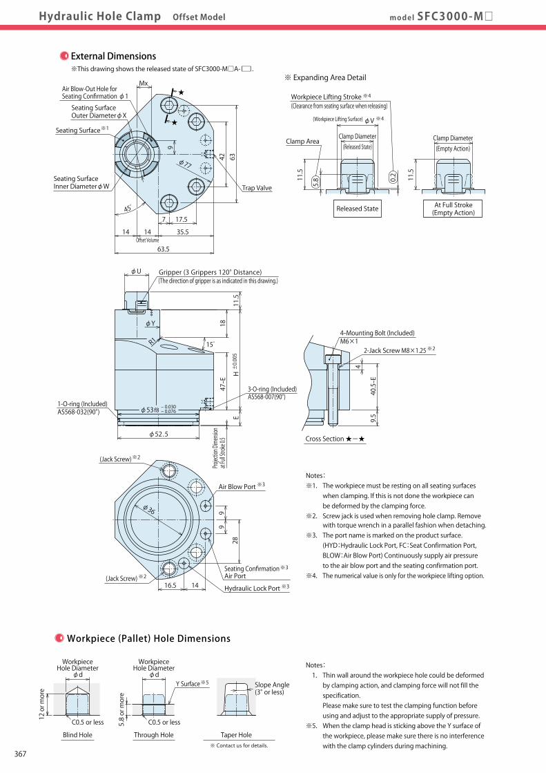
Pneumatic Series
Hydraulic Series
Valve / CouplerHydraulic Unit
Cautions / Others
High-PowerSeries
Manual OperationAccessories
Hole Clamp
SFASFC
Link Clamp
LKALKCLKWLM/LJTMA-2TMA-1
Work Support
LDLCTNCTC
LLW
Air SensingLift Cylinder
Compact Cylinder
LLLLRLLUDPDRDSDT
Block Cylinder
DBADBC
Control Valve
BZLBZTBZX/JZG
Pallet Clamp
VSVT
Expansion Locating Pin
VFLVFMVFJVFK
FPFQ
Pull Stud Clamp
FVAFVDFVC
Centering Vise
DWA/DWB
CustomizedSpring Cylinder
Swing Clamp
LHALHCLHSLHWLT/LGTLA-2TLB-2TLA-1
Hydraulic Hole ClampDigest P.323 CautionsSpecifications
Performance CurveIndex
Action DescriptionSample LayoutCircuit Reference
Model No. Indication
ExternalDimensionsExternalDimensionsmodel SFC3000-M□Hydraulic Hole Clamp Offset Model
Cross Section ★-★
φ36
16.5 14
99
28
Air Blow Port ※3
φ77
6342
Trap Valve
★
★
7 17.5
63.5
14 14 35.5Offset Volume
45゚
9
Seating Surface※1
Mx
External Dimensions※This drawing shows the released state of SFC3000-M□A-□.
Machining Dimensions of Mounting Area
※ Expanding Area Detail
At Full Stroke(Empty Action)
Clamp Diameter(Released State)
Clamp Diameter(Empty Action)
11.5
11.5
φV(Workpiece Lifting Surface) ※4
(Clearance from seating surface when releasing) Workpiece Lifting Stroke ※4
5.8
Clamp Area
0.2
※6Hydraulic Release Port
◆
1
30゚
6.3S 6.3S
7 17.5
63 42
4-M6×1 Thread Depth 11 or more
1416.5
99
Hydraulic Release Port ※6
Air Blow Port φ3
Hydraulic Lock Port φ3
28φ36
φ53H8+ 0.046 0
0.4
φ52.8±0.1
9 or more
E
E+7 or more※7
+ 0.2 0
2.5 or less※7
(Jack Screw)※2
(Jack Screw)※2
Seating SurfaceOuter DiameterφX
Seating SurfaceInner DiameterφW
Notes: ※1. The workpiece must be resting on all seating surfaces when clamping. If this is not done the workpiece can be deformed by the clamping force. ※2. Screw jack is used when removing hole clamp. Remove with torque wrench in a parallel fashion when detaching. ※3. The port name is marked on the product surface. (HYD:Hydraulic Lock Port, FC:Seat Confirmation Port, BLOW:Air Blow Port) Continuously supply air pressure to the air blow port and the seating confirmation port. ※4. The numerical value is only for the workpiece lifting option.
Air Blow-Out Hole for Seating Confirmation φ1
Seating ConfirmationAir Port
※3
Hydraulic Lock Port ※3
Released State
40.5-E
9.5
φ52.5
- 0.030- 0.076φ53f8
EH ±0.005
47-E
15゚
φY
11.5
18
φU
R1
42-Jack Screw M8×1.25
4-Mounting Bolt (Included)M6×1
※2
Gripper (3 Grippers 120° Distance)(The direction of gripper is as indicated in this drawing.)
3-O-ring (Included) AS568-007(90°)
1-O-ring (Included) AS568-032(90°)
Projection Dimension
at Full Stroke 0.5
Notes: 1. Thin wall around the workpiece hole could be deformed by clamping action, and clamping force will not fill the specification. Please make sure to test the clamping function before using and adjust to the appropriate supply of pressure. ※5. When the clamp head is sticking above the Y surface of the workpiece, please make sure there is no interference with the clamp cylinders during machining.
Through Hole Taper Hole
C0.5 or less C0.5 or less
Y Surface※5
※ Contact us for details.
Workpiece (Pallet) Hole Dimensions
Slope Angle(3° or less)
WorkpieceHole Diameter
φd
WorkpieceHole Diameter
φd
Seating ConfirmationAir Portφ3
Blind Hole
5.8 or more
12 or more
Model No. Indication
External Dimensions and Machining Dimensions for Mounting(mm)
4 Lifting Methods
3 Mounting Methods (When selecting M1/M2)
1 Body Size (When selecting 3)
2 Design No.
6 Shape of Gripper (Workpiece Hole)
5 Workpiece Hole Diameter (Workpiece Hole Code)
Notes : 1. There should be no burrs at the hole contact surface. ※6. Release hydraulic pressure can be supplied from the side or bottom surface. Please make a hydraulic release port within ◆ area in the case supplied from the side. Please make a hydraulic release port within area in the case supplied from the bottom. ※7. Base thickness and remaining depth of the lower hole machining (2.5mm) is for when the material is S50C.
3
M1M2
4
AN
21 5
SFC 3 00 0 - 150- -
6
TF
Blank
Notes: ※ 8. The clamping part is an adjusting structure and the clamping operation is done by locating the workpice hole. The numerical value in the table shows the amount of tolerance value of one clamp. Please consider the center distance accuracy of each clamping installation part and each workpiece hole when used with another location clamp / location cylinder, or when using more than two of these products. ※ 9. Workpiece lifting stroke is the function only for lifting option.
※8
※9
Model No.
Workpiece Hole Diameter φd Released State Clamp Diameter Empty Action Allowable Offset (Floating Clearance of Expanding Area) Full Stroke Pulling Stroke Workpiece Lifting Stroke
Mx U V W X Y Mass kg
E
H
5 Workpiece Hole Code+ 0.7- 0.3
+ 0.7- 0.3
+ 0.7- 0.3
+ 0.7- 0.3
+ 0.7- 0.3
+ 0.7- 0.3
+ 0.7- 0.3
SFC3000-M□□-□-□ 130 135 140 145 150 155 160 13 13.5 14 14.5 15 15.5 16 12.5 13 13.5 14 14.5 15 15.5 14.2 14.7 15.2 15.7 16.2 16.7 17.2 ±0.5 4.2 1.0 0.2 10 20 65 55 8.8 8.8 8.8 8.8 8.8 9.6 9.6 12.6 13.1 13.6 14.1 14.6 15.1 15.6 15.5 16 16.5 17 17.5 18 18.5 19 20 20 21 21 22 22 28 28 28 28 28 29 29 29 29 29 29 29 30 30 1.3 1.2
3 Mounting Method M13 Mounting Method M23 Mounting Method M13 Mounting Method M2
3 Mounting Method M13 Mounting Method M2
367
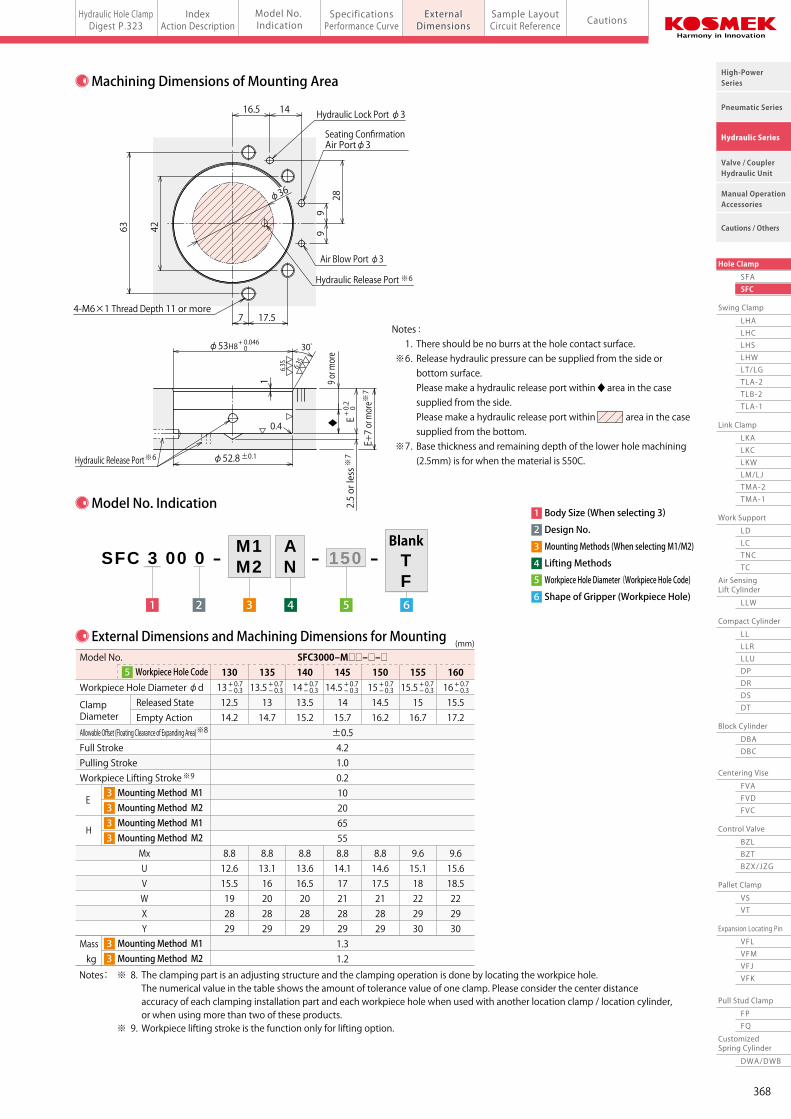
Pneumatic Series
Hydraulic Series
Valve / CouplerHydraulic Unit
Cautions / Others
High-PowerSeries
Manual OperationAccessories
Hole Clamp
SFASFC
Link Clamp
LKALKCLKWLM/LJTMA-2TMA-1
Work Support
LDLCTNCTC
LLW
Air SensingLift Cylinder
Compact Cylinder
LLLLRLLUDPDRDSDT
Block Cylinder
DBADBC
Control Valve
BZLBZTBZX/JZG
Pallet Clamp
VSVT
Expansion Locating Pin
VFLVFMVFJVFK
FPFQ
Pull Stud Clamp
FVAFVDFVC
Centering Vise
DWA/DWB
CustomizedSpring Cylinder
Swing Clamp
LHALHCLHSLHWLT/LGTLA-2TLB-2TLA-1
Hydraulic Hole ClampDigest P.323 CautionsSpecifications
Performance CurveIndex
Action DescriptionSample LayoutCircuit Reference
Model No. Indication
ExternalDimensionsExternalDimensionsmodel SFC3000-M□Hydraulic Hole Clamp Offset Model
Cross Section ★-★
φ36
16.5 14
99
28
Air Blow Port ※3
φ77
6342
Trap Valve
★
★
7 17.5
63.5
14 14 35.5Offset Volume
45゚
9
Seating Surface※1
Mx
External Dimensions※This drawing shows the released state of SFC3000-M□A-□.
Machining Dimensions of Mounting Area
※ Expanding Area Detail
At Full Stroke(Empty Action)
Clamp Diameter(Released State)
Clamp Diameter(Empty Action)
11.5
11.5
φV(Workpiece Lifting Surface) ※4
(Clearance from seating surface when releasing) Workpiece Lifting Stroke ※4
5.8
Clamp Area
0.2
※6Hydraulic Release Port
◆
1
30゚
6.3S 6.3S
7 17.5
63 42
4-M6×1 Thread Depth 11 or more
1416.5
99
Hydraulic Release Port ※6
Air Blow Port φ3
Hydraulic Lock Port φ3
28φ36
φ53H8+ 0.046 0
0.4
φ52.8±0.1
9 or more
E
E+7 or more※7
+ 0.2 0
2.5 or less※7
(Jack Screw)※2
(Jack Screw)※2
Seating SurfaceOuter DiameterφX
Seating SurfaceInner DiameterφW
Notes: ※1. The workpiece must be resting on all seating surfaces when clamping. If this is not done the workpiece can be deformed by the clamping force. ※2. Screw jack is used when removing hole clamp. Remove with torque wrench in a parallel fashion when detaching. ※3. The port name is marked on the product surface. (HYD:Hydraulic Lock Port, FC:Seat Confirmation Port, BLOW:Air Blow Port) Continuously supply air pressure to the air blow port and the seating confirmation port. ※4. The numerical value is only for the workpiece lifting option.
Air Blow-Out Hole for Seating Confirmation φ1
Seating ConfirmationAir Port
※3
Hydraulic Lock Port ※3
Released State
40.5-E
9.5
φ52.5
- 0.030- 0.076φ53f8
EH ±0.005
47-E
15゚
φY
11.5
18
φU
R1
4
2-Jack Screw M8×1.25
4-Mounting Bolt (Included)M6×1
※2
Gripper (3 Grippers 120° Distance)(The direction of gripper is as indicated in this drawing.)
3-O-ring (Included) AS568-007(90°)
1-O-ring (Included) AS568-032(90°)
Projection Dimension
at Full Stroke 0.5
Notes: 1. Thin wall around the workpiece hole could be deformed by clamping action, and clamping force will not fill the specification. Please make sure to test the clamping function before using and adjust to the appropriate supply of pressure. ※5. When the clamp head is sticking above the Y surface of the workpiece, please make sure there is no interference with the clamp cylinders during machining.
Through Hole Taper Hole
C0.5 or less C0.5 or less
Y Surface※5
※ Contact us for details.
Workpiece (Pallet) Hole Dimensions
Slope Angle(3° or less)
WorkpieceHole Diameter
φd
WorkpieceHole Diameter
φd
Seating ConfirmationAir Portφ3
Blind Hole
5.8 or more
12 or more
Model No. Indication
External Dimensions and Machining Dimensions for Mounting(mm)
4 Lifting Methods
3 Mounting Methods (When selecting M1/M2)
1 Body Size (When selecting 3)
2 Design No.
6 Shape of Gripper (Workpiece Hole)
5 Workpiece Hole Diameter (Workpiece Hole Code)
Notes : 1. There should be no burrs at the hole contact surface. ※6. Release hydraulic pressure can be supplied from the side or bottom surface. Please make a hydraulic release port within ◆ area in the case supplied from the side. Please make a hydraulic release port within area in the case supplied from the bottom. ※7. Base thickness and remaining depth of the lower hole machining (2.5mm) is for when the material is S50C.
3
M1M2
4
AN
21 5
SFC 3 00 0 - 150- -
6
TF
Blank
Notes: ※ 8. The clamping part is an adjusting structure and the clamping operation is done by locating the workpice hole. The numerical value in the table shows the amount of tolerance value of one clamp. Please consider the center distance accuracy of each clamping installation part and each workpiece hole when used with another location clamp / location cylinder, or when using more than two of these products. ※ 9. Workpiece lifting stroke is the function only for lifting option.
※8
※9
Model No.
Workpiece Hole Diameter φd Released State Clamp Diameter Empty Action Allowable Offset (Floating Clearance of Expanding Area) Full Stroke Pulling Stroke Workpiece Lifting Stroke
Mx U V W X Y Mass kg
E
H
5 Workpiece Hole Code+ 0.7- 0.3
+ 0.7- 0.3
+ 0.7- 0.3
+ 0.7- 0.3
+ 0.7- 0.3
+ 0.7- 0.3
+ 0.7- 0.3
SFC3000-M□□-□-□ 130 135 140 145 150 155 160 13 13.5 14 14.5 15 15.5 16 12.5 13 13.5 14 14.5 15 15.5 14.2 14.7 15.2 15.7 16.2 16.7 17.2 ±0.5 4.2 1.0 0.2 10 20 65 55 8.8 8.8 8.8 8.8 8.8 9.6 9.6 12.6 13.1 13.6 14.1 14.6 15.1 15.6 15.5 16 16.5 17 17.5 18 18.5 19 20 20 21 21 22 22 28 28 28 28 28 29 29 29 29 29 29 29 30 30 1.3 1.2
3 Mounting Method M13 Mounting Method M23 Mounting Method M13 Mounting Method M2
3 Mounting Method M13 Mounting Method M2
368

Pneumatic Series
Hydraulic Series
Valve / CouplerHydraulic Unit
Cautions / Others
High-PowerSeries
Manual OperationAccessories
Hole Clamp
SFASFC
Link Clamp
LKALKCLKWLM/LJTMA-2TMA-1
Work Support
LDLCTNCTC
LLW
Air SensingLift Cylinder
Compact Cylinder
LLLLRLLUDPDRDSDT
Block Cylinder
DBADBC
Control Valve
BZLBZTBZX/JZG
Pallet Clamp
VSVT
Expansion Locating Pin
VFLVFMVFJVFK
FPFQ
Pull Stud Clamp
FVAFVDFVC
Centering Vise
DWA/DWB
CustomizedSpring Cylinder
Swing Clamp
LHALHCLHSLHWLT/LGTLA-2TLB-2TLA-1
Hydraulic Hole ClampDigest P.323 CautionsSpecifications
Performance CurveIndex
Action DescriptionSample LayoutCircuit Reference
Model No. Indication
ExternalDimensionsmodel SFCHydraulic Hole Clamp Offset Model
When controlled with one solenoid valve
When controlled with two solenoid valves
Seat Check Seat Check Seat Check Seat Check
Seat Check
Air Blow
Release HYD.
Lock HYD.
VFM-D(Datum)
Air Blow
Release HYD.
Lock HYD.
VFM-C(Cut)
Hydraulic Source
Lock Release
Air Blow
Release HYD.
Lock HYD.SFC
Air Blow
Release HYD.
Lock HYD.SFC
Air Blow
Release HYD.
Lock HYD.SFC
Air Blow
Release HYD.
Lock HYD.SFC
Air Source
FilterRecommended:5μm
Seat Check Seat Check Seat Check Seat Check
Seat Check
Air Blow
Release HYD.
Lock HYD.
VFM-D(Datum)
Air Blow
Release HYD.
Lock HYD.
VFM-C(Cut)
Hydraulic Source
Check Valve
Lock Release Lock Release
Air Blow
Release HYD.
Lock HYD.SFC
Air Blow
Release HYD.
Lock HYD.SFC
Air Blow
Release HYD.
Lock HYD.SFC
Air Blow
Release HYD.
Lock HYD.SFC
※2
★Flow Control Valve with Check Valve
Air Source
FilterRecommended:5μm
Air Blow
Air Blow
Air Sensor(Recommended: ISA-G/SMC, GPS2-05-15/CKD)
※3
Air Sensor(Recommended: ISA-G/SMC, GPS2-05-15/CKD)
※3
Check Valve※2
Recommended Air PressureSFC1000:0.4~0.5MPaSFC2000/3000:0.2~0.3MPa
Recommended Air Pressure0.2MPa or less
Recommended Air PressureSFC1000:0.4~0.5MPaSFC2000/3000:0.2~0.3MPa
Recommended Air Pressure0.2MPa or less
Mounting Layout Sample※This drawing shows a combination layout sample of SFC (Hole Clamp) and VM (Expansion Locating Pin). ※ This drawing shows a combination circuit reference of SFC (Hole Clamp) and VFM (Expansion Locating Pin).
Hydraulic and Pneumatic Circuit Reference
Notes: 1. When detaching a workpiece, in order to prevent the clamping part from damage, please set up rough guide of 2 or more. Please refer to the above drawing about the length of rough guide and the diameter gap. (Use of rough guides depends on the loading/unloading condition of the workpiece.) 2. When using a combination of VFM (Expansion Locating Pin) and SFC (Hole Clamp), please choose N:without lift function.
Notes: ※1. Please use solenoid valve to make a sequence operation that SFC (Hole Clamp) starts working after VFM (Expansion Locating Pin) completes the movement. When unable to use solenoid valve, please prepare flow control valve with check valve at ★(1 piece) to adjust sequencing speed. If SFC operates before VFM, there is a possibility for the equipment to be damaged due to a thrust load on SFC. ※2. Expanded VFM cylinder sometimes releases (unclamps) due to a back pressure of tank-port. Please prepare check valve (recommend cracking pressure: less than 0.04MPa). ※3. To reach required accuracy in setting air sensor, please install air sensor for individual clamp.
Base Plate
10mm or more
Z
Vertical
X
YSeating Surface
SFCHole Clamp
Rough Guide(2 or more)
Cut Mark
Diameter Clearance of 1mm or less
VFM-CExpansion Locating Pin
(Cut)
VFM-DExpansion Locating Pin
(Datum)
SFCHole Clamp
SFCHole Clamp
SFCHole Clamp
369

Pneumatic Series
Hydraulic Series
Valve / CouplerHydraulic Unit
Cautions / Others
High-PowerSeries
Manual OperationAccessories
Hole Clamp
SFASFC
Link Clamp
LKALKCLKWLM/LJTMA-2TMA-1
Work Support
LDLCTNCTC
LLW
Air SensingLift Cylinder
Compact Cylinder
LLLLRLLUDPDRDSDT
Block Cylinder
DBADBC
Control Valve
BZLBZTBZX/JZG
Pallet Clamp
VSVT
Expansion Locating Pin
VFLVFMVFJVFK
FPFQ
Pull Stud Clamp
FVAFVDFVC
Centering Vise
DWA/DWB
CustomizedSpring Cylinder
Swing Clamp
LHALHCLHSLHWLT/LGTLA-2TLB-2TLA-1
Hydraulic Hole ClampDigest P.323 CautionsSpecifications
Performance CurveIndex
Action DescriptionSample LayoutCircuit Reference
Model No. Indication
ExternalDimensionsmodel SFCHydraulic Hole Clamp Offset Model
When controlled with one solenoid valve
When controlled with two solenoid valves
Seat Check Seat Check Seat Check Seat Check
Seat Check
Air Blow
Release HYD.
Lock HYD.
VFM-D(Datum)
Air Blow
Release HYD.
Lock HYD.
VFM-C(Cut)
Hydraulic Source
Lock Release
Air Blow
Release HYD.
Lock HYD.SFC
Air Blow
Release HYD.
Lock HYD.SFC
Air Blow
Release HYD.
Lock HYD.SFC
Air Blow
Release HYD.
Lock HYD.SFC
Air Source
FilterRecommended:5μm
Seat Check Seat Check Seat Check Seat Check
Seat Check
Air Blow
Release HYD.
Lock HYD.
VFM-D(Datum)
Air Blow
Release HYD.
Lock HYD.
VFM-C(Cut)
Hydraulic Source
Check Valve
Lock Release Lock Release
Air Blow
Release HYD.
Lock HYD.SFC
Air Blow
Release HYD.
Lock HYD.SFC
Air Blow
Release HYD.
Lock HYD.SFC
Air Blow
Release HYD.
Lock HYD.SFC
※2
★Flow Control Valve with Check Valve
Air Source
FilterRecommended:5μm
Air Blow
Air Blow
Air Sensor(Recommended: ISA-G/SMC, GPS2-05-15/CKD)
※3
Air Sensor(Recommended: ISA-G/SMC, GPS2-05-15/CKD)
※3
Check Valve※2
Recommended Air PressureSFC1000:0.4~0.5MPaSFC2000/3000:0.2~0.3MPa
Recommended Air Pressure0.2MPa or less
Recommended Air PressureSFC1000:0.4~0.5MPaSFC2000/3000:0.2~0.3MPa
Recommended Air Pressure0.2MPa or less
Mounting Layout Sample※This drawing shows a combination layout sample of SFC (Hole Clamp) and VM (Expansion Locating Pin). ※ This drawing shows a combination circuit reference of SFC (Hole Clamp) and VFM (Expansion Locating Pin).
Hydraulic and Pneumatic Circuit Reference
Notes: 1. When detaching a workpiece, in order to prevent the clamping part from damage, please set up rough guide of 2 or more. Please refer to the above drawing about the length of rough guide and the diameter gap. (Use of rough guides depends on the loading/unloading condition of the workpiece.) 2. When using a combination of VFM (Expansion Locating Pin) and SFC (Hole Clamp), please choose N:without lift function.
Notes: ※1. Please use solenoid valve to make a sequence operation that SFC (Hole Clamp) starts working after VFM (Expansion Locating Pin) completes the movement. When unable to use solenoid valve, please prepare flow control valve with check valve at ★(1 piece) to adjust sequencing speed. If SFC operates before VFM, there is a possibility for the equipment to be damaged due to a thrust load on SFC. ※2. Expanded VFM cylinder sometimes releases (unclamps) due to a back pressure of tank-port. Please prepare check valve (recommend cracking pressure: less than 0.04MPa). ※3. To reach required accuracy in setting air sensor, please install air sensor for individual clamp.
Base Plate
10mm or more
Z
Vertical
X
YSeating Surface
SFCHole Clamp
Rough Guide(2 or more)
Cut Mark
Diameter Clearance of 1mm or less
VFM-CExpansion Locating Pin
(Cut)
VFM-DExpansion Locating Pin
(Datum)
SFCHole Clamp
SFCHole Clamp
SFCHole Clamp
370
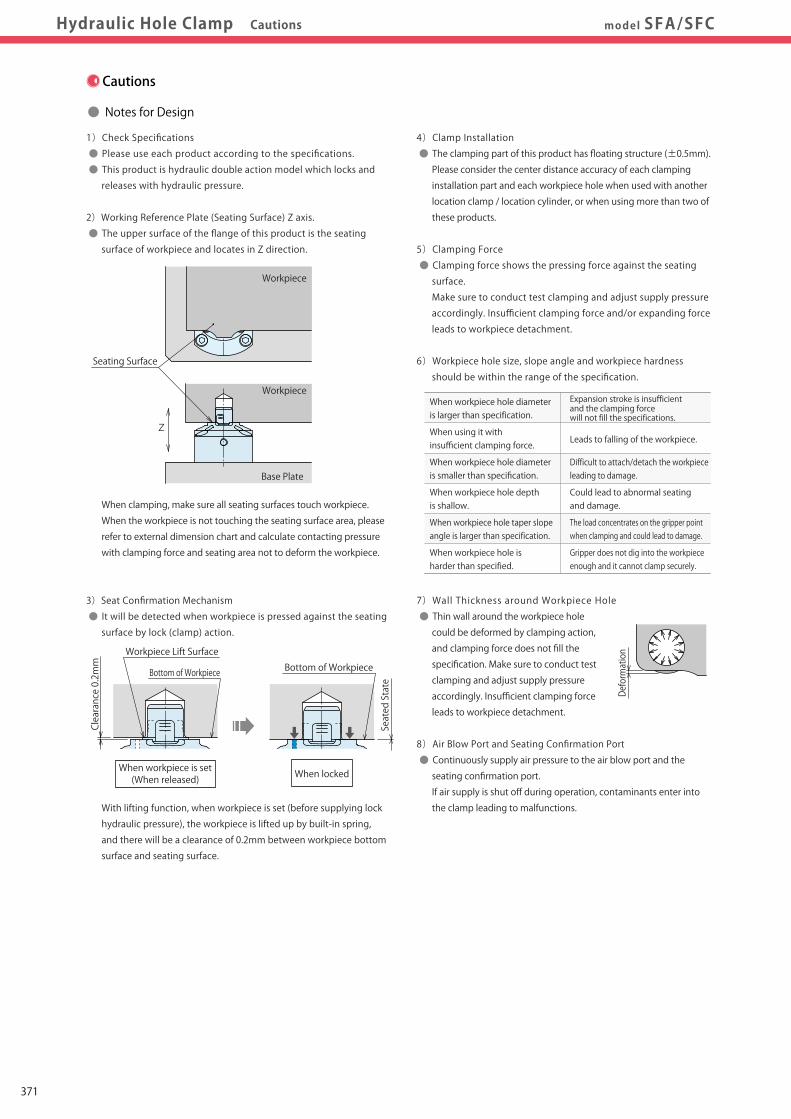
Pneumatic Series
Hydraulic Series
Valve / CouplerHydraulic Unit
Cautions / Others
High-PowerSeries
Manual OperationAccessories
Hole Clamp
SFASFC
Link Clamp
LKALKCLKWLM/LJTMA-2TMA-1
Work Support
LDLCTNCTC
LLW
Air SensingLift Cylinder
Compact Cylinder
LLLLRLLUDPDRDSDT
Block Cylinder
DBADBC
Control Valve
BZLBZTBZX/JZG
Pallet Clamp
VSVT
Expansion Locating Pin
VFLVFMVFJVFK
FPFQ
Pull Stud Clamp
FVAFVDFVC
Centering Vise
DWA/DWB
CustomizedSpring Cylinder
Swing Clamp
LHALHCLHSLHWLT/LGTLA-2TLB-2TLA-1
Hydraulic Hole ClampDigest P.323 CautionsSpecifications
Performance CurveIndex
Action DescriptionSample LayoutCircuit Reference
Model No. Indication
ExternalDimensionsmodel SFA/SFCHydraulic Hole Clamp Cautions
Cautions
● Notes for Design
1)Check Specifications
● Please use each product according to the specifications.
● This product is hydraulic double action model which locks and
releases with hydraulic pressure.
2)Working Reference Plate (Seating Surface) Z axis.
● The upper surface of the flange of this product is the seating
surface of workpiece and locates in Z direction.
When clamping, make sure all seating surfaces touch workpiece.
When the workpiece is not touching the seating surface area, please
refer to external dimension chart and calculate contacting pressure
with clamping force and seating area not to deform the workpiece.
3)Seat Confirmation Mechanism
● It will be detected when workpiece is pressed against the seating
surface by lock (clamp) action.
With lifting function, when workpiece is set (before supplying lock
hydraulic pressure), the workpiece is lifted up by built-in spring,
and there will be a clearance of 0.2mm between workpiece bottom
surface and seating surface.
4)Clamp Installation
● The clamping part of this product has floating structure (±0.5mm).
Please consider the center distance accuracy of each clamping
installation part and each workpiece hole when used with another
location clamp / location cylinder, or when using more than two of
these products.
5)Clamping Force
● Clamping force shows the pressing force against the seating
surface.
Make sure to conduct test clamping and adjust supply pressure
accordingly. Insufficient clamping force and/or expanding force
leads to workpiece detachment.
6)Workpiece hole size, slope angle and workpiece hardness
should be within the range of the specification.
7)Wall Thickness around Workpiece Hole
● Thin wall around the workpiece hole
could be deformed by clamping action,
and clamping force does not fill the
specification. Make sure to conduct test
clamping and adjust supply pressure
accordingly. Insufficient clamping force
leads to workpiece detachment.
8)Air Blow Port and Seating Confirmation Port
● Continuously supply air pressure to the air blow port and the
seating confirmation port.
If air supply is shut off during operation, contaminants enter into
the clamp leading to malfunctions.
9) Release Condition
● When releasing, it lifts up the workpiece which is normal.
When using in a horizontal application, it is recommended to install
work fallout preventions and other temporary stop mechanisms.
10) Horizontal Locating
● When a workpiece is set, please make sure there is no lifting or
slope of the workpiece. If the clamping operation is done with
lifting or slope of the workpiece, it will lead to possible damage
of a clamp and deformation of the workpiece hole.
11) Please detach workpiece with all clamps released completely.
● When a workpiece is detached during lock or release operation,
it will lead to damage of clamp or fall of workpiece.
12) Please set up rough guides.
● When detaching a workpiece with slope it may cause
the damage of clamp or fall of workpiece.
When using the product with other location clamps / cylinders,
please set rough guides considering the center distance accuracy
of each mounting hole and workpiece hole of location clamp /
cylinders.
Seated State
Clearance 0.2mm
Workpiece Lift Surface
Deformation
Z
Seating Surface
Workpiece
Workpiece
Base Plate
Example of Latching Mechanism
When workpiece hole diameter is larger than specification.
Could lead to abnormal seating and damage.
Difficult to attach/detach the workpiece leading to damage.
Leads to falling of the workpiece.
Expansion stroke is insufficient and the clamping force will not fill the specifications.
When using it with insufficient clamping force.
When workpiece hole diameter is smaller than specification.
When workpiece hole depth is shallow.
The load concentrates on the gripper point when clamping and could lead to damage.
When workpiece hole taper slope angle is larger than specification.
Gripper does not dig into the workpiece enough and it cannot clamp securely.
When workpiece hole is harder than specified.
When lockedWhen workpiece is set(When released)
Bottom of WorkpieceBottom of Workpiece
371

Pneumatic Series
Hydraulic Series
Valve / CouplerHydraulic Unit
Cautions / Others
High-PowerSeries
Manual OperationAccessories
Hole Clamp
SFASFC
Link Clamp
LKALKCLKWLM/LJTMA-2TMA-1
Work Support
LDLCTNCTC
LLW
Air SensingLift Cylinder
Compact Cylinder
LLLLRLLUDPDRDSDT
Block Cylinder
DBADBC
Control Valve
BZLBZTBZX/JZG
Pallet Clamp
VSVT
Expansion Locating Pin
VFLVFMVFJVFK
FPFQ
Pull Stud Clamp
FVAFVDFVC
Centering Vise
DWA/DWB
CustomizedSpring Cylinder
Swing Clamp
LHALHCLHSLHWLT/LGTLA-2TLB-2TLA-1
Hydraulic Hole ClampDigest P.323 CautionsSpecifications
Performance CurveIndex
Action DescriptionSample LayoutCircuit Reference
Model No. Indication
ExternalDimensionsmodel SFA/SFCHydraulic Hole Clamp Cautions
Cautions
● Notes for Design
1)Check Specifications
● Please use each product according to the specifications.
● This product is hydraulic double action model which locks and
releases with hydraulic pressure.
2)Working Reference Plate (Seating Surface) Z axis.
● The upper surface of the flange of this product is the seating
surface of workpiece and locates in Z direction.
When clamping, make sure all seating surfaces touch workpiece.
When the workpiece is not touching the seating surface area, please
refer to external dimension chart and calculate contacting pressure
with clamping force and seating area not to deform the workpiece.
3)Seat Confirmation Mechanism
● It will be detected when workpiece is pressed against the seating
surface by lock (clamp) action.
With lifting function, when workpiece is set (before supplying lock
hydraulic pressure), the workpiece is lifted up by built-in spring,
and there will be a clearance of 0.2mm between workpiece bottom
surface and seating surface.
4)Clamp Installation
● The clamping part of this product has floating structure (±0.5mm).
Please consider the center distance accuracy of each clamping
installation part and each workpiece hole when used with another
location clamp / location cylinder, or when using more than two of
these products.
5)Clamping Force
● Clamping force shows the pressing force against the seating
surface.
Make sure to conduct test clamping and adjust supply pressure
accordingly. Insufficient clamping force and/or expanding force
leads to workpiece detachment.
6)Workpiece hole size, slope angle and workpiece hardness
should be within the range of the specification.
7)Wall Thickness around Workpiece Hole
● Thin wall around the workpiece hole
could be deformed by clamping action,
and clamping force does not fill the
specification. Make sure to conduct test
clamping and adjust supply pressure
accordingly. Insufficient clamping force
leads to workpiece detachment.
8)Air Blow Port and Seating Confirmation Port
● Continuously supply air pressure to the air blow port and the
seating confirmation port.
If air supply is shut off during operation, contaminants enter into
the clamp leading to malfunctions.
9) Release Condition
● When releasing, it lifts up the workpiece which is normal.
When using in a horizontal application, it is recommended to install
work fallout preventions and other temporary stop mechanisms.
10) Horizontal Locating
● When a workpiece is set, please make sure there is no lifting or
slope of the workpiece. If the clamping operation is done with
lifting or slope of the workpiece, it will lead to possible damage
of a clamp and deformation of the workpiece hole.
11) Please detach workpiece with all clamps released completely.
● When a workpiece is detached during lock or release operation,
it will lead to damage of clamp or fall of workpiece.
12) Please set up rough guides.
● When detaching a workpiece with slope it may cause
the damage of clamp or fall of workpiece.
When using the product with other location clamps / cylinders,
please set rough guides considering the center distance accuracy
of each mounting hole and workpiece hole of location clamp /
cylinders.
Seated State
Clearance 0.2mm
Workpiece Lift Surface
Deformation
Z
Seating Surface
Workpiece
Workpiece
Base Plate
Example of Latching Mechanism
When workpiece hole diameter is larger than specification.
Could lead to abnormal seating and damage.
Difficult to attach/detach the workpiece leading to damage.
Leads to falling of the workpiece.
Expansion stroke is insufficient and the clamping force will not fill the specifications.
When using it with insufficient clamping force.
When workpiece hole diameter is smaller than specification.
When workpiece hole depth is shallow.
The load concentrates on the gripper point when clamping and could lead to damage.
When workpiece hole taper slope angle is larger than specification.
Gripper does not dig into the workpiece enough and it cannot clamp securely.
When workpiece hole is harder than specified.
When lockedWhen workpiece is set(When released)
Bottom of WorkpieceBottom of Workpiece
372
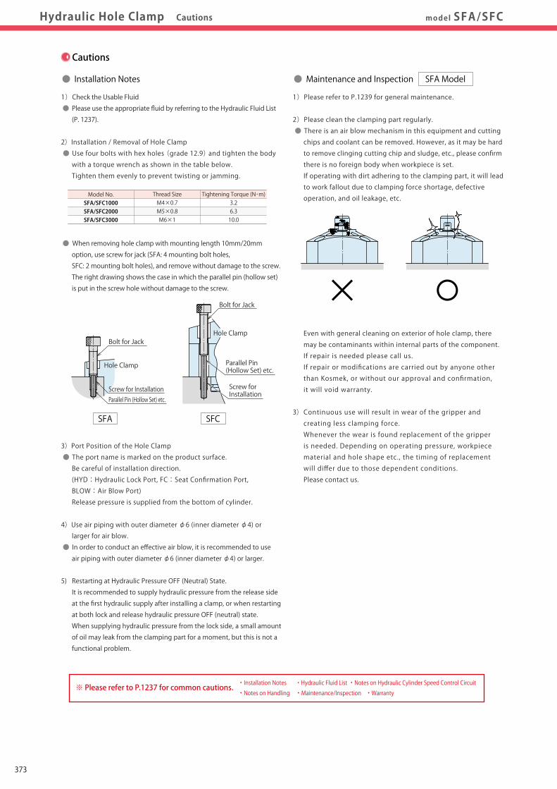
Pneumatic Series
Hydraulic Series
Valve / CouplerHydraulic Unit
Cautions / Others
High-PowerSeries
Manual OperationAccessories
Hole Clamp
SFASFC
Link Clamp
LKALKCLKWLM/LJTMA-2TMA-1
Work Support
LDLCTNCTC
LLW
Air SensingLift Cylinder
Compact Cylinder
LLLLRLLUDPDRDSDT
Block Cylinder
DBADBC
Control Valve
BZLBZTBZX/JZG
Pallet Clamp
VSVT
Expansion Locating Pin
VFLVFMVFJVFK
FPFQ
Pull Stud Clamp
FVAFVDFVC
Centering Vise
DWA/DWB
CustomizedSpring Cylinder
Swing Clamp
LHALHCLHSLHWLT/LGTLA-2TLB-2TLA-1
Hydraulic Hole ClampDigest P.323 CautionsSpecifications
Performance CurveIndex
Action DescriptionSample LayoutCircuit Reference
Model No. Indication
ExternalDimensionsmodel SFA/SFCHydraulic Hole Clamp Cautions
1)Please refer to P.1239 for general maintenance.
2)Please clean the clamping part regularly.
● There is an air blow mechanism in this equipment and cutting
chips and coolant can be removed. However, as it may be hard
to remove clinging cutting chip and sludge, etc., please confirm
there is no foreign body when workpiece is set.
If operating with dirt adhering to the clamping part, it will lead
to work fallout due to clamping force shortage, defective
operation, and oil leakage, etc.
Even with general cleaning on exterior of hole clamp, there
may be contaminants within internal parts of the component.
If repair is needed please call us.
If repair or modifications are carried out by anyone other
than Kosmek, or without our approval and confirmation,
it will void warranty.
3) Continuous use will result in wear of the gripper and
creating less clamping force.
Whenever the wear is found replacement of the gripper
is needed. Depending on operating pressure, workpiece
material and hole shape etc., the timing of replacement
will differ due to those dependent conditions.
Please contact us.
● Maintenance and Inspection SFA Model
MEMOCautions
1)Check the Usable Fluid
● Please use the appropriate fluid by referring to the Hydraulic Fluid List
(P. 1237).
2)Installation / Removal of Hole Clamp
● Use four bolts with hex holes (grade 12.9) and tighten the body
with a torque wrench as shown in the table below.
Tighten them evenly to prevent twisting or jamming.
● When removing hole clamp with mounting length 10mm/20mm
option, use screw for jack (SFA: 4 mounting bolt holes,
SFC: 2 mounting bolt holes), and remove without damage to the screw.
The right drawing shows the case in which the parallel pin (hollow set)
is put in the screw hole without damage to the screw.
3)Port Position of the Hole Clamp
● The port name is marked on the product surface.
Be careful of installation direction.
(HYD:Hydraulic Lock Port, FC:Seat Confirmation Port,
BLOW:Air Blow Port)
Release pressure is supplied from the bottom of cylinder.
4)Use air piping with outer diameter φ6 (inner diameter φ4) or
larger for air blow.
● In order to conduct an effective air blow, it is recommended to use
air piping with outer diameter φ6 (inner diameter φ4) or larger.
5) Restarting at Hydraulic Pressure OFF (Neutral) State.
It is recommended to supply hydraulic pressure from the release side
at the first hydraulic supply after installing a clamp, or when restarting
at both lock and release hydraulic pressure OFF (neutral) state.
When supplying hydraulic pressure from the lock side, a small amount
of oil may leak from the clamping part for a moment, but this is not a
functional problem.
● Installation Notes
Bolt for Jack
Hole Clamp
Parallel Pin (Hollow Set) etc.
Screw for Installation
SFA SFC
Bolt for Jack
Screw for InstallationParallel Pin (Hollow Set) etc.
Hole Clamp
Tightening Torque (N・m)3.26.310.0
Thread SizeM4×0.7M5×0.8M6×1
Model No.SFA/SFC1000SFA/SFC2000SFA/SFC3000
・ Installation Notes ・ Hydraulic Fluid List ・ Notes on Hydraulic Cylinder Speed Control Circuit・ Notes on Handling ・ Maintenance/Inspection ・ Warranty
※ Please refer to P.1237 for common cautions.
373

Pneumatic Series
Hydraulic Series
Valve / CouplerHydraulic Unit
Cautions / Others
High-PowerSeries
Manual OperationAccessories
Hole Clamp
SFASFC
Link Clamp
LKALKCLKWLM/LJTMA-2TMA-1
Work Support
LDLCTNCTC
LLW
Air SensingLift Cylinder
Compact Cylinder
LLLLRLLUDPDRDSDT
Block Cylinder
DBADBC
Control Valve
BZLBZTBZX/JZG
Pallet Clamp
VSVT
Expansion Locating Pin
VFLVFMVFJVFK
FPFQ
Pull Stud Clamp
FVAFVDFVC
Centering Vise
DWA/DWB
CustomizedSpring Cylinder
Swing Clamp
LHALHCLHSLHWLT/LGTLA-2TLB-2TLA-1
Hydraulic Hole ClampDigest P.323 CautionsSpecifications
Performance CurveIndex
Action DescriptionSample LayoutCircuit Reference
Model No. Indication
ExternalDimensionsmodel SFA/SFCHydraulic Hole Clamp Cautions
1)Please refer to P.1239 for general maintenance.
2)Please clean the clamping part regularly.
● There is an air blow mechanism in this equipment and cutting
chips and coolant can be removed. However, as it may be hard
to remove clinging cutting chip and sludge, etc., please confirm
there is no foreign body when workpiece is set.
If operating with dirt adhering to the clamping part, it will lead
to work fallout due to clamping force shortage, defective
operation, and oil leakage, etc.
Even with general cleaning on exterior of hole clamp, there
may be contaminants within internal parts of the component.
If repair is needed please call us.
If repair or modifications are carried out by anyone other
than Kosmek, or without our approval and confirmation,
it will void warranty.
3) Continuous use will result in wear of the gripper and
creating less clamping force.
Whenever the wear is found replacement of the gripper
is needed. Depending on operating pressure, workpiece
material and hole shape etc., the timing of replacement
will differ due to those dependent conditions.
Please contact us.
● Maintenance and Inspection SFA Model
MEMOCautions
1)Check the Usable Fluid
● Please use the appropriate fluid by referring to the Hydraulic Fluid List
(P. 1237).
2)Installation / Removal of Hole Clamp
● Use four bolts with hex holes (grade 12.9) and tighten the body
with a torque wrench as shown in the table below.
Tighten them evenly to prevent twisting or jamming.
● When removing hole clamp with mounting length 10mm/20mm
option, use screw for jack (SFA: 4 mounting bolt holes,
SFC: 2 mounting bolt holes), and remove without damage to the screw.
The right drawing shows the case in which the parallel pin (hollow set)
is put in the screw hole without damage to the screw.
3)Port Position of the Hole Clamp
● The port name is marked on the product surface.
Be careful of installation direction.
(HYD:Hydraulic Lock Port, FC:Seat Confirmation Port,
BLOW:Air Blow Port)
Release pressure is supplied from the bottom of cylinder.
4)Use air piping with outer diameter φ6 (inner diameter φ4) or
larger for air blow.
● In order to conduct an effective air blow, it is recommended to use
air piping with outer diameter φ6 (inner diameter φ4) or larger.
● Installation Notes
Bolt for Jack
Hole Clamp
Parallel Pin (Hollow Set) etc.
Screw for Installation
SFA SFC
Bolt for Jack
Screw for InstallationParallel Pin (Hollow Set) etc.
Hole Clamp
Tightening Torque (N・m)3.26.310.0
Thread SizeM4×0.7M5×0.8M6×1
Model No.SFA/SFC1000SFA/SFC2000SFA/SFC3000
・ Installation Notes ・ Hydraulic Fluid List ・ Notes on Hydraulic Cylinder Speed Control Circuit・ Notes on Handling ・ Maintenance/Inspection ・ Warranty
※ Please refer to P.1237 for common cautions.
374

Notes on Hydraulic Cylinder Speed Control Circuit
Cautions
Installation Notes(For Hydraulic Series)
Hydraulic Fluid List
Notes on Handling
Maintenance/ Inspection
Warranty
Index
Search byAlphabetical Order
Company Profile
Sales Offices
Company Profile
Our Products
History
Pneumatic Series
Hydraulic Series
Valve / CouplerHydraulic Unit
Cautions / Others
High-PowerSeries
Manual OperationAccessories
Installation Notes(For Hydraulic Series)Installation Notes(For Hydraulic Series)
Notes on Hydraulic CylinderSpeed Control Circuit
Notes on Hydraulic CylinderSpeed Control Circuit Maintenance/Inspection WarrantyNotes on HandlingHydraulic Fluid ListHydraulic Fluid ListCautions
Cautions
● Installation Notes (For Hydraulic Series) ● Hydraulic Fluid List
1)Check the Usable Fluid
● Please use the appropriate fluid by referring to the Hydraulic Fluid List.
2)Procedure before Piping
● The pipeline, piping connector and fixture circuits should be cleaned
by thorough flushing.
● The dust and cutting chips in the circuit may lead to fluid leakage
and malfunction.
● There is no filter provided with Kosmek’s product except for a part
of valves which prevents foreign materials and contaminants from
getting into the circuit.
3)Applying Sealing Tape
● Wrap with tape 1 to 2 times following the screw direction.
● Pieces of the sealing tape can lead to oil leakage and malfunction.
● In order to prevent a foreign substance from going into the product
during the piping work, it should be carefully cleaned before working.
4)Air Bleeding of the Hydraulic Circuit
● If the hydraulic circuit has excessive air, the action time may become
very long. If air enters the circuit after connecting the hydraulic port
or under the condition of no air in the oil tank, please perform
the following steps.
① Reduce hydraulic pressure to less than 2MPa.
② Loosen the cap nut of pipe fitting closest to the clamp by one full turn.
③ Wiggle the pipeline to loosen the outlet of pipe fitting.
Hydraulic fluid mixed with air comes out.
④ Tighten the cap nut after bleeding.
⑤ It is more effective to bleed air at the highest point inside the circuit
or at the end of the circuit.
(Set an air bleeding valve at the highest point inside the circuit.)
5)Checking Looseness and Retightening
● At the beginning of the machine installation, the bolt and nut may
be tightened lightly. Check the looseness and re-tighten as required.
Showa Shell SekiyuIdemitsu KosanJX Nippon Oil & EnergyCosmo OilExxonMobilMatsumura OilCastrol
Maker Anti-Wear Hydraulic OilTellus S2 M 32
Daphne Hydraulic Fluid 32Super Hyrando 32Cosmo Hydro AW32Mobil DTE 24Hydol AW-32Hyspin AWS 32
Multi-Purpose Hydraulic OilMorlina S2 B 32
Daphne Super Multi Oil 32Super Mulpus DX 32Cosmo New Mighty Super 32Mobil DTE 24 Light
Note As it may be difficult to purchase the products as shown in the table from overseas, please contact the respective manufacturer.
ISO Viscosity Grade ISO-VG-32
Flow Control at the Release Side
W
Flow Control Valve(Any location is OK)
Sequence Valve
● Notes on Hydraulic Cylinder Speed Control Unit
Please pay attention to the cautions below. Design the hydraulic circuit for controlling the action speed of hydraulic cylinder.
Improper circuit design may lead to malfunctions and damages. Please review the circuit design in advance.! ● Flow Control Circuit for Single Acting Cylinder For spring return single acting cylinders, restricting flow during release can extremely slow down or disrupt release action. The preferred method is to control the flow during the lock action using a valve that has free-flow in the release direction. It is also preferred to provide a flow control valve at each actuator.
Accelerated clamping speed by excessive hydraulic flow to the cylinder may sustain damage. In this case add flow control to regulate flow. (Please add flow control to release flow if the lever weight is put on at the time of release action when using swing clamps.)
● Flow Control Circuit for Double Acting Cylinder Flow control circuit for double acting cylinder should have meter-out circuits for both the lock and release sides. Meter-in control can have adverse effect by presence of air in the system. However, in the case of controlling LKE, TMA, TLA, both lock side
and release side should be meter-in circuit.
Refer to P.75 for speed adjustment of LKE.
For TMA and TLA, if meter-out circuit is used, abnormal high
pressure is created, which causes oil leakage and damage.
【Meter-out Circuit】 (Except LKE/TMA/TLA)
【Meter-in Circuit】 (LKE/TMA/TLA must be controlled with meter-in.)
In the case of meter-out circuit, the hydraulic circuit should be designed with the following points. ① Single acting components should not be used in the same flow control circuit as the double acting components. The release action of the single acting cylinders may become erratic or very slow.
Refer to the following circuit when both the single acting cylinder and double acting cylinder are used together. ○ Separate the control circuit.
○ Reduce the influence of double acting cylinder control unit. However, due to the back pressure in tank line, single action cylinder is activated after double action cylinder works.
② In the case of meter-out circuit, the inner circuit pressure may increase during the cylinder action because of the fluid supply. The increase of the inner circuit pressure can be prevented by reducing the supplied fluid beforehand via the flow control valve. Especially when using sequence valve or pressure switches for clamping detection. If the back pressure is more than the set pressure then the system will not work as it is designed to.
1237

Notes on Hydraulic Cylinder Speed Control Circuit
Cautions
Installation Notes(For Hydraulic Series)
Hydraulic Fluid List
Notes on Handling
Maintenance/ Inspection
Warranty
Index
Search byAlphabetical Order
Company Profile
Sales Offices
Company Profile
Our Products
History
Pneumatic Series
Hydraulic Series
Valve / CouplerHydraulic Unit
Cautions / Others
High-PowerSeries
Manual OperationAccessories
Installation Notes(For Hydraulic Series)Installation Notes(For Hydraulic Series)
Notes on Hydraulic CylinderSpeed Control Circuit
Notes on Hydraulic CylinderSpeed Control Circuit Maintenance/Inspection WarrantyNotes on HandlingHydraulic Fluid ListHydraulic Fluid ListCautions
Cautions
● Installation Notes (For Hydraulic Series) ● Hydraulic Fluid List
1)Check the Usable Fluid
● Please use the appropriate fluid by referring to the Hydraulic Fluid List.
2)Procedure before Piping
● The pipeline, piping connector and fixture circuits should be cleaned
by thorough flushing.
● The dust and cutting chips in the circuit may lead to fluid leakage
and malfunction.
● There is no filter provided with Kosmek’s product except for a part
of valves which prevents foreign materials and contaminants from
getting into the circuit.
3)Applying Sealing Tape
● Wrap with tape 1 to 2 times following the screw direction.
● Pieces of the sealing tape can lead to oil leakage and malfunction.
● In order to prevent a foreign substance from going into the product
during the piping work, it should be carefully cleaned before working.
4)Air Bleeding of the Hydraulic Circuit
● If the hydraulic circuit has excessive air, the action time may become
very long. If air enters the circuit after connecting the hydraulic port
or under the condition of no air in the oil tank, please perform
the following steps.
① Reduce hydraulic pressure to less than 2MPa.
② Loosen the cap nut of pipe fitting closest to the clamp by one full turn.
③ Wiggle the pipeline to loosen the outlet of pipe fitting.
Hydraulic fluid mixed with air comes out.
④ Tighten the cap nut after bleeding.
⑤ It is more effective to bleed air at the highest point inside the circuit
or at the end of the circuit.
(Set an air bleeding valve at the highest point inside the circuit.)
5)Checking Looseness and Retightening
● At the beginning of the machine installation, the bolt and nut may
be tightened lightly. Check the looseness and re-tighten as required.
Showa Shell SekiyuIdemitsu KosanJX Nippon Oil & EnergyCosmo OilExxonMobilMatsumura OilCastrol
Maker Anti-Wear Hydraulic OilTellus S2 M 32
Daphne Hydraulic Fluid 32Super Hyrando 32Cosmo Hydro AW32Mobil DTE 24Hydol AW-32Hyspin AWS 32
Multi-Purpose Hydraulic OilMorlina S2 B 32
Daphne Super Multi Oil 32Super Mulpus DX 32Cosmo New Mighty Super 32Mobil DTE 24 Light
Note As it may be difficult to purchase the products as shown in the table from overseas, please contact the respective manufacturer.
ISO Viscosity Grade ISO-VG-32
Flow Control at the Release Side
W
Flow Control Valve(Any location is OK)
Sequence Valve
● Notes on Hydraulic Cylinder Speed Control Unit
Please pay attention to the cautions below. Design the hydraulic circuit for controlling the action speed of hydraulic cylinder.
Improper circuit design may lead to malfunctions and damages. Please review the circuit design in advance.! ● Flow Control Circuit for Single Acting Cylinder For spring return single acting cylinders, restricting flow during release can extremely slow down or disrupt release action. The preferred method is to control the flow during the lock action using a valve that has free-flow in the release direction. It is also preferred to provide a flow control valve at each actuator.
Accelerated clamping speed by excessive hydraulic flow to the cylinder may sustain damage. In this case add flow control to regulate flow. (Please add flow control to release flow if the lever weight is put on at the time of release action when using swing clamps.)
● Flow Control Circuit for Double Acting Cylinder Flow control circuit for double acting cylinder should have meter-out circuits for both the lock and release sides. Meter-in control can have adverse effect by presence of air in the system. However, in the case of controlling LKE, TMA, TLA, both lock side
and release side should be meter-in circuit.
Refer to P.75 for speed adjustment of LKE.
For TMA and TLA, if meter-out circuit is used, abnormal high
pressure is created, which causes oil leakage and damage.
【Meter-out Circuit】 (Except LKE/TMA/TLA)
【Meter-in Circuit】 (LKE/TMA/TLA must be controlled with meter-in.)
In the case of meter-out circuit, the hydraulic circuit should be designed with the following points. ① Single acting components should not be used in the same flow control circuit as the double acting components. The release action of the single acting cylinders may become erratic or very slow.
Refer to the following circuit when both the single acting cylinder and double acting cylinder are used together. ○ Separate the control circuit.
○ Reduce the influence of double acting cylinder control unit. However, due to the back pressure in tank line, single action cylinder is activated after double action cylinder works.
② In the case of meter-out circuit, the inner circuit pressure may increase during the cylinder action because of the fluid supply. The increase of the inner circuit pressure can be prevented by reducing the supplied fluid beforehand via the flow control valve. Especially when using sequence valve or pressure switches for clamping detection. If the back pressure is more than the set pressure then the system will not work as it is designed to.
1238

Notes on Hydraulic Cylinder Speed Control Circuit
Cautions
Installation Notes(For Hydraulic Series)
Hydraulic Fluid List
Notes on Handling
Maintenance/ Inspection
Warranty
Index
Search byAlphabetical Order
Company Profile
Sales Offices
Company Profile
Our Products
History
Pneumatic Series
Hydraulic Series
Valve / CouplerHydraulic Unit
Cautions / Others
High-PowerSeries
Manual OperationAccessories
Installation Notes(For Hydraulic Series)
Notes on Hydraulic CylinderSpeed Control Circuit Maintenance/InspectionMaintenance/Inspection WarrantyWarrantyNotes on HandlingNotes on HandlingHydraulic Fluid ListCautions
1)Warranty Period
● The product warranty period is 18 months from shipment from
our factory or 12 months from initial use, whichever is earlier.
2)Warranty Scope
● If the product is damaged or malfunctions during the warranty
period due to faulty design, materials or workmanship, we will
replace or repair the defective part at our expense.
Defects or failures caused by the following are not covered.
① If the stipulated maintenance and inspection are not carried out.
② If the product is used while it is not suitable for use based on
the operator’s judgment, resulting in defect.
③ If it is used or handled in inappropriate way by the operator.
(Including damage caused by the misconduct of the third party.)
④ If the defect is caused by reasons other than our responsibility.
⑤ If repair or modifications are carried out by anyone other than Kosmek,
or without our approval and confirmation, it will void warranty.
⑥ Other caused by natural disasters or calamities not attributable to
our company.
⑦ Parts or replacement expenses due to parts consumption and
deterioration.
(Such as rubber, plastic, seal material and some electric components.)
Damages excluding from direct result of a product defect shall be
excluded from the warranty.
● Warranty
Cautions
1)It should be handled by qualified personnel.
● The hydraulic machine and air compressor should be handled
and maintained by qualified personnel.
2)Do not handle or remove the machine unless the safety protocols
are ensured.
① The machine and equipment can only be inspected or prepared
when it is confirmed that the preventive devices are in place.
② Before the machine is removed, make sure that the above-mentioned
safety measures are in place. Shut off the air of hydraulic source
and make sure no pressure exists in the hydraulic and air circuit.
③ After stopping the machine, do not remove until the temperature
cools down.
④ Make sure there is no abnormality in the bolts and respective parts
before restarting the machine or equipment.
3)Do not touch clamp (cylinder) while clamp (cylinder) is working.
Otherwise, your hands may be injured due to clinching.
4)Do not disassemble or modify.
● If the equipment is taken apart or modified, the warranty will be
voided even within the warranty period.
1)Removal of the Machine and Shut-off of Pressure Source
● Before the machine is removed, make sure that the
above-mentioned safety measures are in place. Shut off the
air of hydraulic source and make sure no pressure exists in
the hydraulic and air circuit.
● Make sure there is no abnormality in the bolts and respective
parts before restarting.
2)Regularly clean the area around the piston rod and plunger.
● If it is used when the surface is contaminated with dirt, it may
lead to packing seal damage, malfunctioning, fluid leakage
and air leaks.
3) Please clean out the reference surface regularly (taper reference
surface and seating surface) of locating machine. (VS/VT/VFL/
VFM/VFJ/VFK/WVS/VWM/VWK/VX/VXF)
● Location products, except VX/VXF model, can remove
contaminants with cleaning functions.
When installing pallets makes sure there is no thick sludge like
substances on pallets.
● Continuous use with dirt on components will lead to locating
functions not work properly, leaking and malfunction.
4) If disconnecting by couplers on a regular basis, air bleeding
should be carried out daily to avoid air mixed in the circuit.
5)Regularly tighten nuts, bolts, pins, cylinders and pipe line to
ensure proper use.
6)Make sure the hydraulic fluid has not deteriorated.
7)Make sure there is smooth action and no abnormal noise.
● Especially when it is restarted after left unused for a long
period, make sure it can be operated correctly.
8)The products should be stored in the cool and dark place
without direct sunshine or moisture.
9)Please contact us for overhaul and repair.
● Notes on Handling ● Maintenance and Inspection
1239

Notes on Hydraulic Cylinder Speed Control Circuit
Cautions
Installation Notes(For Hydraulic Series)
Hydraulic Fluid List
Notes on Handling
Maintenance/ Inspection
Warranty
Index
Search byAlphabetical Order
Company Profile
Sales Offices
Company Profile
Our Products
History
Pneumatic Series
Hydraulic Series
Valve / CouplerHydraulic Unit
Cautions / Others
High-PowerSeries
Manual OperationAccessories
Installation Notes(For Hydraulic Series)
Notes on Hydraulic CylinderSpeed Control Circuit Maintenance/InspectionMaintenance/Inspection WarrantyWarrantyNotes on HandlingNotes on HandlingHydraulic Fluid ListCautions
1)Warranty Period
● The product warranty period is 18 months from shipment from
our factory or 12 months from initial use, whichever is earlier.
2)Warranty Scope
● If the product is damaged or malfunctions during the warranty
period due to faulty design, materials or workmanship, we will
replace or repair the defective part at our expense.
Defects or failures caused by the following are not covered.
① If the stipulated maintenance and inspection are not carried out.
② If the product is used while it is not suitable for use based on
the operator’s judgment, resulting in defect.
③ If it is used or handled in inappropriate way by the operator.
(Including damage caused by the misconduct of the third party.)
④ If the defect is caused by reasons other than our responsibility.
⑤ If repair or modifications are carried out by anyone other than Kosmek,
or without our approval and confirmation, it will void warranty.
⑥ Other caused by natural disasters or calamities not attributable to
our company.
⑦ Parts or replacement expenses due to parts consumption and
deterioration.
(Such as rubber, plastic, seal material and some electric components.)
Damages excluding from direct result of a product defect shall be
excluded from the warranty.
● Warranty
Cautions
1)It should be handled by qualified personnel.
● The hydraulic machine and air compressor should be handled
and maintained by qualified personnel.
2)Do not handle or remove the machine unless the safety protocols
are ensured.
① The machine and equipment can only be inspected or prepared
when it is confirmed that the preventive devices are in place.
② Before the machine is removed, make sure that the above-mentioned
safety measures are in place. Shut off the air of hydraulic source
and make sure no pressure exists in the hydraulic and air circuit.
③ After stopping the machine, do not remove until the temperature
cools down.
④ Make sure there is no abnormality in the bolts and respective parts
before restarting the machine or equipment.
3)Do not touch clamp (cylinder) while clamp (cylinder) is working.
Otherwise, your hands may be injured due to clinching.
4)Do not disassemble or modify.
● If the equipment is taken apart or modified, the warranty will be
voided even within the warranty period.
1)Removal of the Machine and Shut-off of Pressure Source
● Before the machine is removed, make sure that the
above-mentioned safety measures are in place. Shut off the
air of hydraulic source and make sure no pressure exists in
the hydraulic and air circuit.
● Make sure there is no abnormality in the bolts and respective
parts before restarting.
2)Regularly clean the area around the piston rod and plunger.
● If it is used when the surface is contaminated with dirt, it may
lead to packing seal damage, malfunctioning, fluid leakage
and air leaks.
3) Please clean out the reference surface regularly (taper reference
surface and seating surface) of locating machine. (VS/VT/VFL/
VFM/VFJ/VFK/WVS/VWM/VWK/VX/VXF)
● Location products, except VX/VXF model, can remove
contaminants with cleaning functions.
When installing pallets makes sure there is no thick sludge like
substances on pallets.
● Continuous use with dirt on components will lead to locating
functions not work properly, leaking and malfunction.
4) If disconnecting by couplers on a regular basis, air bleeding
should be carried out daily to avoid air mixed in the circuit.
5)Regularly tighten nuts, bolts, pins, cylinders and pipe line to
ensure proper use.
6)Make sure the hydraulic fluid has not deteriorated.
7)Make sure there is smooth action and no abnormal noise.
● Especially when it is restarted after left unused for a long
period, make sure it can be operated correctly.
8)The products should be stored in the cool and dark place
without direct sunshine or moisture.
9)Please contact us for overhaul and repair.
● Notes on Handling ● Maintenance and Inspection
1240
Company Profile
Overseas Affiliates and Sales OfficesDistributors
CanadaU.S.A.CanadaU.S.A.
EuropeEurope
Asia
BrazilBrazil
Asia
Australia
MexicoMexico
JapanChina
Taiwan
PhilippinesThailand
Japan
Korea
China
Taiwan
PhilippinesThailand
IndiaIndia
Korea
SingaporeSingaporeMalaysiaMalaysia
IndonesiaIndonesia
Global Network
Asia Detailed Map
● FOR FURTHER INFORMATION ON UNLISTED SPECIFICATIONS AND SIZES, PLEASE CALL US.● SPECIFICATIONS IN THIS CATALOG ARE SUBJECT TO CHANGE WITHOUT NOTICE.
JQA-QMA10823KOSMEK HEAD OFFICE
Sales Offices
TEL.078-991-5115 FAX.078-991-8787
Sales Offices in Japan
〒651-2241 兵庫県神戸市西区室谷2丁目1番5号
Tokyo Sales OfficeTEL.048-652-8839 FAX.048-652-8828
〒331-0815 埼玉県さいたま市北区大成町4丁目81番地
Nagoya Sales OfficeTEL.0566-74-8778 FAX.0566-74-8808
〒446-0076 愛知県安城市美園町2丁目10番地1
Fukuoka Sales OfficeTEL.092-433-0424 FAX.092-433-0426
〒812-0006 福岡県福岡市博多区上牟田1丁目8-10-101
Head OfficeOsaka Sales OfficeOverseas Sales
Japan
Overseas Sales
TEL. +81-78-991-5162 FAX. +81-78-991-8787
Sales Offices across the World
〒651-2241 兵庫県神戸市西区室谷2丁目1番5号
USA
KOSMEK(USA)LTD.
G.E.T. Inc, Phil.
TEL. +1-630-620-7650 FAX. +1-630-620-9015650 Springer Drive, Lombard, IL 60148 USA
EUROPE
KOSMEK EUROPE GmbH
TEL. +43-463-287587 FAX. +43-463-287587-20Schleppeplatz 2 9020 Klagenfurt am Wörthersee Austria
Thailand TEL. +66-2-300-5132 FAX. +66-2-300-5133 67 Soi 58, RAMA 9 Rd., Suanluang, Suanluang, Bangkok 10250, Thailand
Victoria Wave Special Economic Zone Mt. Apo Building, Brgy. 186, North Caloocan City, Metro Manila, Philippines 1427
China
考世美(上海)貿易有限公司
TEL.+86-21-54253000 FAX.+86-21-54253709
中国上海市浦东新区浦三路21弄55号银亿滨江中心601室200125
Taiwan
盈生貿易有限公司
Thailand Representative Office
Mexico TEL. +52-442-161-2347Blvd Jurica la Campana 1040, B Colonia Punta Juriquilla Queretaro, QRO 76230 MexicoKOSMEK USA Mexico Office
TEL. +886-2-82261860 FAX. +886-2-82261890
台湾新北市中和區建八路2號 16F-4(遠東世紀廣場)
Philippines TEL.+63-2-310-7286 FAX. +63-2-310-7286
P.T PANDU HYDRO PNEUMATICS Ruko Green Garden Blok Z-Ⅱ No.51 Rt.005 Rw.008 Kedoya Utara-Kebon Jeruk Jakarta Barat 11520 Indonesia
Indonesia TEL. +62-21-5818632 FAX. +62-21-5814857
16F-4, No.2, Jian Ba Rd., Zhonghe District, New Taipei City Taiwan 23511
Room601, RIVERSIDE PYRAMID No.55, Lane21, Pusan Rd, Pudong Shanghai 200125, China
KOSMEK LTD. 1-5, 2-chome, Murotani, Nishi-ku, Kobe-city, Hyogo, Japan 651-2241
KOSMEK(CHINA)LTD.
Full Life Trading Co., Ltd.
(Indonesia Exclusive Distributor)
(Philippines Exclusive Distributor)
(Taiwan Exclusive Distributor)
India
KOSMEK LTD. - INDIA
TEL.+91-9880561695F 203, Level-2, First Floor, Prestige Center Point, Cunningham Road, Bangalore -560052 India