Embed Size (px)
Citation preview

HYDRAULIC MOTORS MR
32
Specification data ........... ....29÷30
Function diagrams ........... ...31÷
Dimensions and mounting .....
Shaft extensions ................. ...... 2
Permissible shaft loads ......... .....
Order code ........................ ......
....
.... 39
40÷41
... 8
. 29
Permissible shaft Seal Pressure ... 30
..... 42
CONTENTS OPTIONS
»
»
»
»
»
»
»
»
»
Model- Spool valve, roll-gerotor
Flange mount
Motor with needle bearing
Side and rear ports
Shafts- straight, splined and tapered
Shaft seal for high and low pressure
Metric and BSPP ports
Speed sensoring
Other special features
APPLICATION
»
»
»
»
»
»
Conveyors
Feeding mechanism of robots and manipulators
Metal working machines
Textile machines
Food industries
» Agriculture machines
etc.Grass cutting machinery
75 [20]
10
Mineral based- HLP(DIN 51524) or HM(ISO 6743/4)
4 14 [ 40 284]
[ ]
ISO code 20/16 (Min. recommended fluid filtration of 25 micron)
- 0÷ 0 - ÷
20÷75 98÷347
GENERAL
Max. Displacement,
Max. Speed,
Max. Torque,
Max. Output,
Max. Pressure Drop,
Max. Oil Flow,
Min. Speed,
Pressure fluid
Temperature range,
Optimal Viscosity range,
Filtration
cm /rev [in /rev]
[RPM]
daNm [lb-in]
kW [HP]
bar [PSI]
lpm [GPM]
[RPM]
C [ F]
mm /s [SUS]
3 3
O O
2
397 24.4
61 5400
75 2540
[ ]
[ ]
[ ]
[ ]
970
69 [6100]
15 20.1
cont.: int.:
cont.: 1 int.: 200 [2900]
Pressure Losses
2,5 .660
1,8 .476
3,5 .925
2,8 .740
[ ]
[ ]
[ ]
[ ]
Oil flow in drain line
7020 60504030100 Q, lpm
0 2 84 106 12 Q, GPM
80
0
100
200
400
300
0
5
10
15
20
25
pbar
pPSI
14 16 18 20
30
140 [2030]
210 3045[ ]
Pressure drop
[ ]bar PSI
Viscosity
[ ]mm /s SUS2
Oil flow indrain line
[ ]lpm GPM
20 98
35 164
20 [98]
35 [164]
[ ]
[ ]

Type
Displacement,
[ ]
Max. Speed,
[RPM]
Max. Torque
[ ]
Max. Output
[ ]
Max. Pressure Drop
[ ]
Max. Oil Flow
[ ]
Max. Inlet Pressure
[ ]
Max. Return Pres-
sure with Drain Line
[ ]
Max. Starting Pressure with
Unloaded Shaft, [ ]
Min. Starting Torque
[ ]
Min. Speed***, [RPM]
Weight, [ ]
3
3
cm /rev
in /rev
daNm in-lb
kW HP
bar PSI
lpm GPM
bar PSI
bar PSI
bar PSI
daNm in-lb
kg lb
For rear ports + [ ]: 0,650 1.433
Cont.
Int.*
Cont.
Int.*
Peak**
Cont.
Int.*
Cont.
Int.*
Peak**
Cont.
Int.*
Cont.
Int.*
Peak**
Cont.
Int.*
Peak**
M (F)
MRQ(N)
At max.press.
drop Cont.
At max.press.
drop Int.*
R
900]
1150]
1505]
9.5]
11.9]
2030]
2540]
3260]
10 ]
1 ]
2540]
2900]
3260]
3260]
145]
710]
85]
15]
13.7]
[
[
[
[
[
[
[
[
[ .5
[ 3.2
[
[
[
[
[
[
[
[
[
[
[
2540]
2900]
10
13
17
7
8,5
140
175
225
175
200
225
225
10
8
10
6,8
6,2
775
970
40
50
51,5
[3.14]
175
200
10
MR
50
MR
80
17 ]
1947]
2390]
17]
20.1]
2540]
2900]
3260]
1 ]
]
2540]
2900]
3260]
2540]
2900]
3260]
145]
1330]
1505]
15,2]
13.9]
[ 70
[
[
[
[
[
[
[
[ 5.8
[19.8
[
[
[
[
[
[
[
[
[
[
[
[ ]
750
940
22
27
12,5
15
175
200
225
60
175
200
225
175
200
225
10
15
17
6,9
6,3
80,3
4.90
20
75
10
2125]
2480]
2832]
17.4]
20.1]
2540]
2900]
3260]
1 ]
]
2540]
2900]
3260]
2540]
2900]
3260]
145]
1770]
2035]
15.9]
14.6]
[
[
[
[
[
[
[
[
[ 5.8
[19.8
[
[
[
[
[
[
[
[
[
[
[
MR
100
2655]
3010]
3275]
16.8]
19.5]
2540]
2900]
3260]
]
]
2540]
2900]
3260]
2540]
2900]
3260]
130]
2215]
2480]
16.1]
15]
[
[
[
[
[
[
[
[
[15.8
[19.8
[
[
[
[
[
[
[
[
[
[
[
MR
125
3450]
3805]
4070]
15.4]
18.8]
2540]
2900]
3260]
]
]
2540]
2900]
3260]
2540]
2900]
3260]
102]
2832]
3275]
15.2]
15.4]
[
[
[
[
[
[
[
[
[15.8
[19.8
[
[
[
[
[
[
[
[
[
[
[
MR
160
3410]
4070]
4960]
12]
]
2030]
2540]
3260]
]
]
2540]
2900]
3260]
2540]
2900]
3260]
73]
2920]
3540]
17.6]
14.7]
[
[
[
[
[16.1
[
[
[
[15.8
[19.8
[
[
[
[
[
[
[
[
[
[
[
MR
200
3450]
]
]
]
1 ]
1600]
]
]
]
]
2540]
2900]
3260]
2540]
2900]
3260]
58]
2740]
4250]
18.5]
17.2]
[
[4160
[5310
[10.7
[ 2.7
[
[2030
[2900
[15.8
[19.8
[
[
[
[
[
[
[
[
[
[
[
MR
250
MR
315
3 ]
]
]
]
]
]
]
]
]
]
2540]
2900]
3260]
44]
]
522
20]
19]
[ 185
[4160
[5400
[6.7
[10.7
[1230
[1670
[2175
[15.8
[19.8
[
[
[
[
[
[
[
[2875
[ 0]
[
[
2540]
2900]
3260]
3360]
]
]
6.4]
]
0]
]
]
]
]
2540]
2900]
3260]
2540]
2900]
3260]
44]
]
4425]
21.6]
20.5]
[
[4160
[5400
[
[9.1
[94
[1300
[1670
[15.8
[19.8
[
[
[
[
[
[
[
[
[
[
[
2875
MR
400
[
60
75
24
28
32
13
15
175
200
225
60
175
200
225
175
200
225
10
20
23
10
7,2
6,6
99,8
6.09]
0
0
75
[
4
60
30
34
37
12,5
14,5
175
200
225
60
175
200
225
175
200
225
9
25
28
10
7,3
6,8
125,7
7.67]
75
0
75
[
3
47
39
43
46
11,5
14
175
200
225
60
175
200
225
175
200
225
7
32
37
10
7,5
7,6
159,6
9.74]
75
0
75
[
30
37
38,5
46
56
9
140
175
225
60
175
200
225
175
200
225
5
33
40
10
8
7,2
199,8
12.19]
0
5
12
75
[
240
30
39
,5
110
1
2
60
175
200
225
175
200
225
4
31
48
10
8,4
7,8
250,1
15.26]
0
47
60
8
9
40
00
75
315,7
19.26
175
200
225
[
190
240
3
7
1
0
60
175
200
225
3
58
10
9,1
8,6
]
6
4
61
5
8
85
15
15
75
31,5
[
15
19
38
4,8
,8
1 5
60
175
200
225
175
200
225
3
50
10
9,8
9,3
397
24.4
0
0
]
47
61
6
65
90
1
75
31,5
33
MOTORS
MR
SPECIFICATION DATA
Specification Data for MR... motors with , , , and shafts.C CO SH K SA
(ø28,56 sealing diameter)
* Intermittent operation: the permissible values may occur for max. 10% of every minute.
** Peak load: the permissible values may occur for max. 1% of every minute.
*** For speeds lower than given, consult factory or your regional manager.
1. Intermittent speed and intermittent pressure must not occur simultaneously.
2. Recommended filtration is per ISO cleanliness code 20/16. A nominal f ltration of 25 micron or better.
3. Recommend using a premium quality, anti-wear type mineral based hydraulic oil HM ( ISO 6743/4).If using synthetic fluids consult the factory for alternative seal materials.
4. Recommended minimum oil viscosity 13 mm²/s [70 SUS] at 50°C [122°F].
5. Recommended maximum system operating temperature is 82°C [180°F].
6. To assure optimum motor life fill with fluid prior to loading and run at moderate load and speed for 10-15 minutes.
i
HLP(DIN51524) or
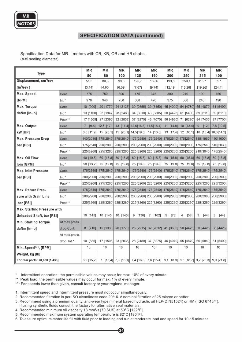
SPECIFICATION DATA (continued)
34
MOTORS
MR
Specification Data for MR... motors with CB, KB, OB and HB shafts.
(ø35 sealing diameter)
* Intermittent operation: the permissible values may occur for max. 10% of every minute.
** Peak load: the permissible values may occur for max. 1% of every minute.
*** For speeds lower than given, consult factory or your regional manager.
1. Intermittent speed and intermittent pressure must not occur simultaneously.
2. Recommended filtration is per ISO cleanliness code 20/16. A nominal f ltration of 25 micron or better.
3. Recommend using a premium quality, anti-wear type mineral based hydraulic oil HM ( ISO 6743/4).If using synthetic fluids consult the factory for alternative seal materials.
4. Recommended minimum oil viscosity 13 mm²/s [70 SUS] at 50°C [122°F].
5. Recommended maximum system operating temperature is 82°C [180°F].
6. To assure optimum motor life fill with fluid prior to loading and run at moderate load and speed for 10-15 minutes.
i
HLP(DIN51524) or
Type
Cont.
Int.*
Cont.
Int.*
Peak**
Cont.
Int.*
Cont.
Int.*
Peak**
Cont.
Int.*
Cont.
Int.*
Peak**
Cont.
Int.*
Peak**
At max.press.
drop Cont.
At max.press.
drop Int.*
MR
50
MR
80
MR
100
MR
125
MR
160
MR
200
MR
250
MR
315
MR
400
[
7
10
13
17
7
8,5
140
175
225
5
175
200
225
175
200
225
10
8
10
10
6,9
40
0
51,5
3.14]
75
970
[
750
940
22
27
12,5
15
175
200
225
175
200
25
175
200
225
10
5
17
10
7
80,3
4.90
60
]
20
75
2
1
[
60
75
24
28
32
13
15
175
200
225
60
200
225
175
200
225
10
20
23
10
7,3
0
99,8
6.09
175
]
0
75
[
4
60
30
34
37
12,5
14,5
175
200
225
200
225
175
200
225
9
25
28
10
7,4
75
125,7
7.67
60
175
]
0
75
[
37
47
39
43
46
11,5
14
175
200
225
60
175
200
225
175
200
225
7
32
37
10
7,6
159,6
9.74]
5
0
75
[
30
37
45
50
56
11
13
175
200
225
60
175
200
225
175
200
225
5
41
46
10
8,1
199,8
12.19]
0
5
75
[
240
30
54
61
71
10
12
175
200
225
60
75
200
225
175
200
225
4
55
10
8,5
250,1
15.26]
0
75
1
50
[
190
24
55
6
8
9
1
135
1
210
60
175
200
225
175
200
225
3
66
10
9,2
315,7
19.26]
0
9
4
0
75
75
50
[
15
19
61
69
87
7,8
10,6
11
140
175
60
175
200
225
175
200
225
3
61
10
9,9
397
24.4]
0
0
0
75
50
Displacement,
Max. Speed,
[RPM]
Max. Torque
[ ]
Max. Output
[ ]
Max. Pressure Drop
[ ]
Max. Oil Flow
[ ]
Max. Inlet Pressure
[ ]
Max. Return Pres-
sure with Drain Line
[ ]
Max. Starting Pressure with
Unloaded Shaft, [ ]
Min. Starting Torque
[ ]
Min. Speed***, [RPM]
Weight, [ ]
cm /rev
[in /rev ]
daNm in-lb
kW HP
bar PSI
lpm GPM
bar PSI
bar PSI
bar PSI
daNm in-lb
kg lb
3
3
For rear ports + [ ]: 0,650 1.433
4000]
4425]
4960]
14.8]
17.4]
2540]
2900]
3260]
2540]
2900]
3260]
2540]
2900]
3260]
73]
3630]
4070]
18.9]
[
[
[
[
[
[
[
[
[
[
[
[
[
[
[
[
[
[
[ 5.8
[19.8
1 ]
]
4780]
5400]
6280]
13.4]
16.1]
2540]
2900]
3260]
2540]
2900]
3260]
2540]
2900]
3260]
58]
4 ]
4870]
18.7]
[
[
[
[
[
[
[
[
[
[
[
[
[
[
[
[
[
[
[ 5.8
[19.8
425
1 ]
]
4870]
]
7 ]
12]
1 ]
1960]
]
3045]
2540]
2900]
3260]
2540]
2900]
3260]
44]
]
5840]
20.3]
[
[
[
[
[
[
[
[
[
[
[
[
[
[
[
[
[
[
6110
435
3.4
2540
[ 5.8
[19.8
425
1 ]
]
4
5400]
61 0]
7700]
10.5]
14.2]
16 0]
2030]
2540]
2540]
2900]
3260]
2540]
2900]
3260]
44]
]
5400]
21.8]
[
[
[
[
[
[
[
[
[
[
[
[
[
[
[
[
[
[
1
0
[ 5.8
[19.8
425
1 ]
]
4
2655]
3010]
3275]
16.8]
19.5]
2540]
2900]
3260]
2540]
2900]
3260]
2540]
2900]
3260]
130]
2215]
2480]
16.3]
[
[
[
[
[
[
[
[
[
[
[
[
[
[
[
[
[
[
[ 5.8
[19.8
1 ]
]
3450]
3805]
4070]
15.4]
18.8]
2540]
2900]
3260]
2540]
2900]
3260]
2540]
2900]
3260]
102]
2832]
3275]
15.4]
[
[
[
[
[
[
[
[
[
[
[
[
[
[
[
[
[
[
[ 5.8
[19.8
1 ]
]
17 ]
1947]
2390]
17]
20.1]
2540]
2900]
3260]
1 ]
]
2540]
2900]
3260]
2540]
2900]
3260]
145]
1330]
1505]
15,4]
[ 70
[
[
[
[
[
[
[
[ 5.8
[19.8
[
[
[
[
[
[
[
[
[
[
2125]
2480]
2832]
17.4]
20.1]
2540]
2900]
3260]
2540]
2900]
3260]
2540]
2900]
3260]
145]
1770]
2035]
16.1]
[
[
[
[
[
[
[
[
[
[
[
[
[
[
[
[
[
[
[ 5.8
[19.8
1 ]
]
900]
1150]
1505]
9.5]
11.9]
2030]
2540]
3260]
10 ]
1 ]
2540]
2900]
3260]
2540]
2900]
3260]
145]
710]
885]
15,2]
[
[
[
[
[
[
[
[
[ .5
[ 3.2
[
[
[
[
[
[
[
[
[
[

MOTORS
MR 50
MR 80
FUNCTION DIAGRAMS
35
MR
The function diagrams data is for average performance of randomly selected motors at back pressure5÷10 bar [72.5÷145 PSI] and oil with viscosity of 32 mm²/s [150 SUS] at 50°C [122 F].
o
0,5kW
1kW
2kW
6kW
4kW
8kW
MdaNm
0
2
4
6
8
10
12
14
16
18
20
0
Mlb-in
200
400
600
800
1600
1000
1200
1400
1800
222000
70 bar1020 PSI
50 bar730 PSI
n
cont.
int.
cont. int.
p=175 bar2540 PSI
140 bar2030 PSI
MdaNm
0
1
2
3
4
5
Mlb-in
6
7
8
9
10
11
12
0 RPM400200 600 800700 900100 300 500 1000
120 bar1740 PSI
30 bar430 PSI
100 bar1450 PSI
20
l/m
in5.3
GP
M
30
l/m
in7.9
GP
M
40
l/m
in10.6
GP
M
35
l/m
in9.2
GP
M
10
l/m
in2.6
GP
M
50
l/m
in13.2
GP
M
Q=
5l/m
in1.3
GP
M
45
l/m
in11.9
GP
M
25
l/m
in6.6
GP
M
15
l/m
in4.0
GP
M
20
l/m
in5.3
GP
M
30
l/m
in7.9
GP
M
40
l/m
in10.6
GP
M
10
l/m
in2.6
GP
M
50
l/m
in13.2
GP
M
70
l/m
in18.5
GP
M
60
l/m
in15.9
GP
M
Q=
5l/m
in1.3
GP
M
75
l/m
in19.8
GP
M
0
100
200
300
400
500
600
700
800
900
1000
1100
0 RPM400200 600 800700 900100 300 500
ncont. int.
p=200 bar2900 PSI
80 bar1160 PSI
60 bar870 PSI
30 bar430 PSI
100 bar1450 PSI
140 bar2030 PSI
120 bar1740 PSI
175 bar2540 PSI

36
MOTORS
MR 100
MR 125
FUNCTION DIAGRAMS
MR
0
800
1200
1600
2000
2400
400
2800
3200
The function diagrams data is for average performance of randomly selected motors at back pressure5÷10 bar [72.5÷145 PSI] and oil with viscosity of 32 mm²/s [150 SUS] at 50°C [122 F].
o
MdaNm
0 RPM
n
cont.
int.
cont. int.
400200 600
20
l/m
in5.3
GP
M
30
l/m
in7.9
GP
M
40
l/m
in10.6
GP
M
10
l/m
in2.6
GP
M
50
l/m
in13.2
GP
M
70
l/m
in18.5
GP
M
60
l/m
in15.9
GP
M
Q=
5l/m
in1.3
GP
M
75
l/m
in19.8
GP
M
100 300 500
0
4
8
12
16
20
0
Mlb-in
500
1000
1500
24
2000
282500
700
p=200 bar2900 PSI
80 bar1160 PSI
60 bar870 PSI
30 bar430 PSI
100 bar1450 PSI
140 bar2030 PSI
120 bar1740 PSI
175 bar2540 PSI
MdaNm
0 RPM
n
cont.
int.
cont. int.
400200 600
20
l/m
in5.3
GP
M
30
l/m
in7.9
GP
M
40
l/m
in10.6
GP
M
10
l/m
in2.6
GP
M
50
l/m
in13.2
GP
M
70
l/m
in18.5
GP
M
60
l/m
in15.9
GP
M
Q=
5l/m
in1.3
GP
M
75
l/m
in19.8
GP
M
100 300 500
0
4
8
12
16
20
Mlb-in
24
32 p=200 bar2900 PSI
80 bar1160 PSI
60 bar870 PSI
30 bar430 PSI
100 bar1450 PSI
140 bar2030 PSI
120 bar1740 PSI
175 bar2540 PSI
28
36

37
MOTORS
MR 160
MR 200
FUNCTION DIAGRAMS
MR
The function diagrams data is for average performance of randomly selected motors at back pressure5÷10 bar [72.5÷145 PSI] and oil with viscosity of 32 mm²/s [150 SUS] at 50°C [122 F].
o
MdaNm
RPM
n
cont.
int.
cont. int.
20
l/m
in5.3
GP
M
30
l/m
in7.9
GP
M
40
l/m
in10.6
GP
M
10
l/m
in2.6
GP
M
50
l/m
in13.2
GP
M
70
l/m
in18.5
GP
M
60
l/m
in15.9
GP
M
Q=
5l/m
in1.3
GP
M
75
l/m
in19.8
GP
M
0
4
8
12
16
20
24
32
p=200 bar2900 PSI
80 bar1160 PSI
60 bar870 PSI
30 bar430 PSI
100 bar1450 PSI
140 bar2030 PSI
120 bar1740 PSI
175 bar2540 PSI
28
36
40
44
MdaNm
RPM
n
cont.
int.
cont. int.
20
l/m
in5.3
GP
M
30
l/m
in7.9
GP
M
40
l/m
in10.6
GP
M
10
l/m
in2.6
GP
M
50
l/m
in13.2
GP
M
70
l/m
in18.5
GP
M
60
l/m
in15.9
GP
M
Q=
5l/m
in1.3
GP
M
75
l/m
in19.8
GP
M
Mlb-in
p=200 bar2900 PSI
80 bar1160 PSI
60 bar870 PSI
30 bar430 PSI
105 bar1520 PSI
140 bar2030 PSI
120 bar1740 PSI
175 bar2540 PSI
0
800
1200
1600
2000
2400
400
2800
3200
Mlb-in
3600
4000
0 400200100 300 450250150 35050
0
5
10
15
20
25
0
1000
1500
2000
302500
353000
40
45
500
3500
4000
4500 50
0 200100 300250150 35050

38
MOTORS
MR
MR 250
MR 315
FUNCTION DIAGRAMS
35
MdaNm
0
5
10
15
20
25
Mlb-in
30
40
45
50
55
60
65
0
1000
1500
2000
2500
3000
500
3500
4000
4500
5000
5500
6000
RPM0 200100 2251505025 75 125 175 250 300275
The function diagrams data is for average performance of randomly selected motors at back pressure5÷10 bar [72.5÷145 PSI] and oil with viscosity of 32 mm²/s [150 SUS] at 50°C [122 F].
o
0
8
16
24
32
40
48
56
72
64
n
cont.
int.
cont. int.
20
l/m
in5.3
GP
M
30
l/m
in7.9
GP
M
40
l/m
in10.6
GP
M
10
l/m
in2.6
GP
M
50
l/m
in13.2
GP
M
70
l/m
in18.5
GP
M
60
l/m
in15.9
GP
M
Q=
5l/m
in1.3
GP
M
75
l/m
in19.8
GP
M
p=200 bar2900 PSI
80 bar1160 PSI
60 bar870 PSI
30 bar430 PSI
105 bar1520 PSI
140 bar2030 PSI
175 bar2540 PSI
110 bar1600 PSI
ncont. int.
20
l/m
in5.3
GP
M
30
l/m
in7.9
GP
M
40
l/m
in10.6
GP
M
10
l/m
in2.6
GP
M
50
l/m
in13.2
GP
M
70
l/m
in18.5
GP
M
60
l/m
in15.9
GP
M
Q=
5l/m
in1.3
GP
M
75
l/m
in19.8
GP
M
p=175 bar2540 PSI
135 bar1740 PSI
30 bar430 PSI
160 bar2320 PSI
80 bar1160 PSI
cont.
int.
0
1000
1500
2000
2500
3000
500
3500
4000
4500
5000
5500
6000
6500
0 200100 2251505025 75 125 175 RPM
MdaNm
Mlb-in
65 bar940 PSI
45 bar650 PSI
125 bar1810 PSI

MR 400
39
The function diagrams data is for average performance of randomly selected motors at back pressure5÷10 bar [72.5÷145 PSI] and oil with viscosity of 32 mm²/s [150 SUS] at 50°C [122 F].
o
MOTORS
MR
FUNCTION DIAGRAMS
20
l/m
in5.3
GP
M
30
l/m
in7.9
GP
M
40
l/m
in10.6
GP
M
10
l/m
in2.6
GP
M
50
l/m
in13.2
GP
M
70
l/m
in18.5
GP
M
60
l/m
in15.9
GP
M
Q=
5l/m
in1.3
GP
M
75
l/m
in19.8
GP
M
MdaNm
0
4
8
12
16
20
24
32
28
36
40
44
0
800
1200
1600
2000
2400
400
2800
3200
Mlb-in
3600
4000
48
52
56
60
64
4400
4800
5200
5600
RPM
ncont. int.
100 20 30 5040 60 70 9080 100 110 120 130 140 150 160 170 180 190
15
l/m
in4.0
GP
M
p=125 bar1810 PSI
65 bar940 PSI
40 bar580 PSI
30 bar430 PSI
80 bar1160 PSI
90 bar1300 PSI
110 bar1600 PSI
55 bar800 PSI

DIMENSIONS AND MOUNTING DATA
40
MOTORS
MR
138,0
143,0
146,0
150,5
156,5
163,5
172,0
183,0
198,0
143,5
148,5
152,0
156,5
162,5
169,5
179,0
189,0
204,0
157,5
162,5
165,5
170,0
176,0
183,0
192,0
204,0
218,0
163,5
168,5
171,5
176,0
182,0
189,0
198,0
210,0
224,0
9,0
14,0
17,4
21,8
27,8
34,8
43,5
54,8
69,4
MR(F) 50
MR(F) 80
MR(F) 100
MR(F) 125
MR(F) 160
MR(F) 200
MR(F) 250
MR(F) 315
MR(F) 400
MR(F)E 50
MR(F)E 80
MR(F)E 100
MR(F)E 125
MR(F)E 160
MR(F)E 200
MR(F)E 250
MR(F)E 315
MR(F)E 400
MRQ 50
MRQ 80
MRQ 100
MRQ 125
MRQ 160
MRQ 200
MRQ 250
MRQ 315
MRQ 400
MRQE 50
MRQE 80
MRQE 100
MRQE 125
MRQE 160
MRQE 200
MRQE 250
MRQE 315
MRQE 400
C
P
T
: 4xM8 - 13 mm depth
: 2xG1/2 or 2xM22x1,5 - 15 mm [.59 in] depth
: G1/4 or M14x1,5 - 12 mm [.47 in] depth (plugged)
[.51 in]
(A, B)
Standard Rotation
A CW
B CCW
Viewed from Shaft EndPort Pressurized -Port Pressurized -
Reverse Rotation
A CCW
B CW
Viewed from Shaft EndPort Pressurized -Port Pressurized -
Shaft Dim.See Page 28
Flange Dim.See Page 41
Port Dim.See Page 41
ma
xL
L1
max ø105
[ ]4,134
38
±0
,15
ma
xL
74
±0
,3
SA Shaft K ShaftSH Shaft C Shaft CO Shaft
ma
x5
5
ma
x5
5
[2.1
65
]
[2.1
65
]
SA Shaft K ShaftSH Shaft C Shaft CO Shaft
ma
x4
9
[1.9
29
]
ma
x4
9
[1.9
29
]
[1.4
96
±.0
05
9]
[2.9
13
±.0
11
8]
E Rear ports
mm [in]
C
T
P(A,B)
80
±0
,3
44
±0
,15
[1.7
32
±.0
05
9]
ma
xL
L1
C
P(A,B)
max ø105
[ ]4,134
Port B
Port A
Port B
Port A
[3.1
49
±.0
11
8]
L, mm [in] L , mm1
[in]Type Type Type TypeL, mm [in] L, mm [in] L, mm [in]
[5.43]
[5.63]
[5.75]
[5.93]
[6.16]
[6.44]
[6.77]
[7.20]
[7.80]
[5.65]
[5.85]
[5.98]
[6.16]
[6.40]
[6.67]
[7.05]
[7.44]
[8.03]
[6.20]
[6.40]
[6.52]
[6.69]
[6.93]
[7.20]
[7.56]
[8.03]
[8.58]
[6.44]
[6.63]
[6.75]
[6.93]
[7.17]
[7.44]
[7.80]
[8.27]
[8.82]
[ .35]
[ .55]
[ .69]
[ .86]
[1.09]
[1.37]
[1.71]
[2.16]
[2.73]
SB Shaft
OB Shaft CB Shaft HB Shaft
ma
x1
4
ma
x6
8,3
[2.6
89
]
[.5
51
]ma
x7
0
[2.7
56
]
KB Shaft
mm [in]
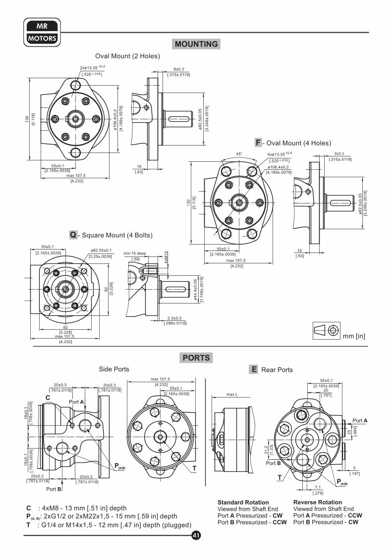
E Rear PortsSide Ports
Oval Mount (2 Holes)
F - Oval Mount (4 Holes)
C
P
T
: 4xM8 - 13 mm depth
: 2xG1/2 or 2xM22x1,5 - 15 mm [.59 in] depth
: G1/4 or M14x1,5 - 12 mm [.47 in] depth (plugged)
[.51 in]
(A, B)
Standard Rotation
A CW
B CCW
Viewed from Shaft EndPort Pressurized -Port Pressurized -
Reverse Rotation
A CCW
B CW
Viewed from Shaft EndPort Pressurized -Port Pressurized -
2xø13,35 +0,4
+.016[.525 ]
55±0,1
[2.165±.0039]
max 107,5
[ ]4,232
13
0
[5.1
18
]
[4.1
89
±.0
07
9]
ø1
06
,4±
0,2
Q - Square Mount (4 Bolts)
55±0,1
[2.165±.0039]ø82,55±0,1
min 15 deep
[.59]
2,3±0,3
[.098±.0118]
[3.25±.0039]
82
[3.228]
82
[3.2
28
]
4xM
10
Port B
18
±0
,1
[.7
08
±.0
03
9]
P(A,B)
20±0,3
[.787±.0118]
20±0,3
[.787±.0118]
20±0,3
[.787±.0118]
20±0,3
[.787±.0118]
18
±0
,1
[.7
08
±.0
03
9]
55±0,1
[2.165±.0039]
C
T
TP
(A,B)
max L
Port A
Port B
ø8
2,5
±0
,05
[3.2
48
±.0
01
9]
16
8±0,3
[.63]
[.315±.0118]
41
MOTORS
MR
ø8
2,5
±0
,05
[3.2
48
±.0
01
9]
16
[.63]
8±0,3
[.315±.0118]
max 107,5
[ ]4,232
ø4
4,4
±0
,05
[1.7
48
±.0
01
9]
55±0,1
[2.165±.0039]
[4.189±.0079]
ø106,4±0,2
4xø13,35+0,4
+.016[.525 ]
450
13
0
[5.1
18
]
max 107,5
[ ]4,232
Port A
max 107,5
[ ]4,232
5
[. ]197
55±0,1
[2.165±.0039]
7,1
[.279]
31
,2
[1.2
3]
25
[.9
84
]
20
[.787]
MOUNTING
PORTS

ORDER CODE
42
MOTORS
MR
* The permissible output torque for shafts must not be exceeded!
- 51,5 cm /rev [3.14 in /rev]
- 80,3 cm /rev [4.90 in /rev]
- 99,8 cm /rev [6.09 in /rev]
- 125,7 cm /rev [7.67 in /rev]
- 159,6 cm /rev [9.74 in /rev]
- 199,8 cm /rev [12.19 in /rev]
- 250,1 cm /rev [15.26 in /rev]
- 315,7 cm /rev [19.26 in /rev]
- 397,0 cm /rev [24.40 in /rev]
50
80
100
125
160
200
250
315
400
3 3
3 3
3 3
3 3
3 3
3 3
3 3
3 3
3 3
M R
Pos.1 - Mounting Flange
Pos.2 - (needle bearings)Option
Pos.3 - Port type
Pos.4 - Displacement code
1 2 3 4 5 6 7 8 10
omit - none
- needle bearingsN with
omit - Side ports
- Rear portsE
Pos.5 - *Shaft Extensions (see page 28)
omit - Oval mount
- Oval mount
- S
, two holes
, four holes
quare mount, four bolts
- Wheel mount
F
Q
W
NOTES Q ...B
N ...B U
...B D U
: The following combinations are not allowed: - flange with “ ” shafts;
- option with “ ” shafts, Low Pressure Seal or option;
- “ ” shafts with and shaft seals.
The hydraulic motors are mangano-phosphatized as standard.
9
- ø25 straight, Parallel key A8x7x32 DIN6885
- ø25 straight, Parallel key A8x7x32 DIN6885
with corrosion resistant bushing
- ø1" straight, Parallel key ¼"x¼"x1¼" BS46
- ø1" straight, Parallel key ¼"x¼"x1¼" BS46
with corrosion resistant bushing
- ø25,32 splined BS 2059 (SAE 6B)- ø25,32 splined BS 2059 (SAE 6B)
with corrosion resistant bushing
- ø28,56 tapered 1:10, Parallel key B5x5x14 DIN6885
- ø24,5 splined B 25x22 DIN 5482
- ø24,5 splined B 25x22 DIN 5482
with corrosion resistant bushing
C
VC
CO
VCO
SH
VSH
K
SA
VSA
- ø32 straight, Parallel key A10x8x45 DIN6885
- ø35 tapered 1:10, Parallel key B6x6x20 DIN6885
- splined A 25x22 DIN 5482
- ø1¼" tapered1:8, Parallel key "x "x1¼" BS46
- ø1¼" splined 14T ANSI B92.1 - 1976
CB
KB
SB
OB
HB
omit - BSPP (ISO 228)
- Metric (ISO 262)M
Pos. 8 - Ports
omit - with drain port
- without drain port1
Pos. 7 - Drain Port
Pos.10 - Design Series
omit - Factory specified
Pos. 6 - Shaft Seal Version (see page 30)
omit - Low pressure shaft seal or Standard shaft seal
for “... ” shaft
- Standard shaft seal
- High pressure shaft seal (without check valves)
B
D
U
Pos. 9 - Special Features (see page 98)

Hydraulic motors type MR...T with tacho connection
MR motors are available in version with tacho drive shaft. With tacho connection the
speed of the motor can be registered. Tacho shaft has a 6 times higher revolution
speed than output shaft and opposite direction of rotation.
The main technical features correspond to the standard motors series MR. There are nochanges in the overall and mounting dimensions.
MRFor detail technical and mounting data please
refer to catalogue.
Note: Radial or axial load on tacho shaft must be avoided. Max. torque on tacho shaft 0,1 daNm
[.885 lb-in]. Max. cont. return pressure without drain line 20 bar [290 PSI].
A
B
43
OUTLINE DIMENSIONS REFERENCE
157
162
165
170
176
183
192
204
218
9,0
14,0
17,4
21,8
27,8
34,8
43,5
54,8
69,4
MR 50
MR 80
MR 100
MR 125
MR 160
MR 200
MR 250
MR 315
MR 400 mm [in]
L , mm1
[in]Type L, mm [in]
[6.18]
[6.38]
[6.50]
[6.69]
[6.93]
[7.20]
[7.56]
[8.03]
[8.58]
[ .35]
[ .55]
[ .69]
[ .86]
[1.09]
[1.37]
[1.71]
[2.16]
[2.73]
3±
0,0
5
[.11
8±
.00
19
]
ø9
[.354]
26,4
39[1.535]
[1.039]
26
[1.024]
Drain port - G1/8(M10x1 for metric ports)min 10 mm [.39 in] deep
A
max L
L1
[1.1
81
]ø
30
ø6
0
M2
2x1
,5
10,3
6,5
[.256]
[.405]
[2.3
62
]
B

SPECIFICATION DATA
* Intermittent operation: the permissible values may occur for max. 10% of every minute.
MRNA is suitable for driven mechanism where is demand smooth
operation low speed and high pressure. It is designed with
separated output shaft and spool valve and can be specified with
low internal leakage.
A
B
» Good start-up characteristics;
» Precise control of the Torque at low
small flow.
»
»
Smooth operation at high pressure and
small oil flow;
High volumetric efficiency.
» Actuator motor as driving-motor for steering
mechanism of the the three-wheel vehicles;
» For conveyors (series connection);
» Dosing motor etc.
T L
RP
HydraulicReservoir
44
HYDRAULIC MOTORS MRNA
APPLICATION
MRNA 50
80
100
125
160
200
250
315
400
MRNA
MRNA
MRNA
MRNA
MRNA
MRNA
MRNA
MRNA
51,5
[3.14]
80,3
[4.9]
99,8
[6.09]
125,7
[7.67]
159,6
[9.74]
199,8
[12.19]
250,1
[15.26]
315,7
[19.26]
397,0
[24.4]
Displa-
cement
cm /rev
[in /rev]
3
3
Max.
Speed
[RPM]
Max. Torque
daNm [lb-in]
Max. Pressure
Drop, bar [PSI]
Max. Oil
Flow, lpm
[GPM]
cont. cont. cont.
Code
int* int* cont.
Max. Output
kW [HP]
cont. int*
200
200
200
200
200
200
200
190
150
10
[885]
20
[1770]
24
2120
30
[2650]
29
[2560]
29
30
30
30
[2560]
[2650]
[2650]
[2650]
13
[1150]
22
[1940]
28
[2480]
34
[3000]
39
[3450]
38,5
[3400]
39
[3450]
42
[3720]
40
[3540]
2,0
[2.68]
3,0
[4.02]
4,5
[6.03]
5,5
[7.37]
5,0
[6.71]
5,0
[6.71]
5,0
5,0
4,0
[[5.36]
[6.71]
[6.71]
2,5
[3.35]
3,5
[4.69]
5,0
6,0
[8.05]
6,5
7,0
[9.39]
7,0
7,5
[10.05]
6,5
[8.72]
[6.71]
[8.05]
[9.39]
140
[2030]
175
[2540]
175
175
120
[1740]
105
[1520]
80
[1160]
70
[1020]
55
[800]
[2540]
[2540]
175
200
[2900]
200
200
175
140
110
[1600]
100
[1450]
70
[1015]
[2540]
[2900]
[2900]
[2540]
[2030]
10,5
[2.8]
16
[4.2]
20
[5.3]
25
[6.6]
32
[8.5]
40
[10.5]
50
[13.2]
65
[17.2]
60
[15.8]
C, CO shafts SH, SA shafts
cont. int*
140
[2030]
175
[2540]
175
[2540]
175
[2540]
[2540]
[2030]
[1600]
175
140
110
85
[1230]
65
[940]
175
[2540]
200
[2900]
200
[2900]
200
[2900]
[2900]
[2540]
[2030]
200
175
140
115
[1670]
90
[1300]
cont. int*
10
[885]
20
[1770]
24
2120
30
[2650]
[3450]
[3450]
[3450]
39
38,5
[3400]
39
36
38
[3260]
13
[1150]
22
[1940]
28
[2480]
34
[3000]
[4160]
[4160]
43
[3800]
46
[4070]
47
[4160]
47
47
C, CO shafts SH, SA shafts C, CO shafts SH, SA shafts
cont. int*
2,0
[2.68]
3,0
[4.02]
4,5
[6.03]
5,5
[7.37]
[8.05]
[8.72]
[8.05]
[8.05]
[8.05]
6,0
6,5
6,0
6,0
6,0
2,5
[3.35]
3,5
[4.69]
5,0
[6.71]
6,0
[8.05]
[10.05]
[12.06]
[9.39]
7,5
9,0
[12.06]
9,0
8,5
[11.4]
7,0
The main technical features correspond to the standard motors
series MR ø28,56 [1.124 in.] sealing diameter. There are no
changes in the overall and mounting dimensions. For detail
technical and mounting data please refer to MR catalogue.

45
HYDRAULIC MOTORS MRFL
The hydraulic motors type MRFL... and MLHRFL... are designed for use in operating modes withpeak radial loads of the output shaft (especially at starting and stopping) at direct drive of wheels ormechanisms (without clutch or gearbox).
The radial loads are borne by a radial ball bearing which is mounted on the shaft of the hydraulicmotor.
For detail technical andmounting data please refer to MR catalogue.
The main technical features correspond to the standard motors series MRF ø35 [1.378 in.] sealingdiameter. There are no changes in the overall and mounting dimensions.
PERMISSIBLE SHAFT LOADS
0
1000
Pr
daN
200
2000
Pradlbs
60 40 20 0 mm
1000
10 -1070 50 30
800
600
400
1 002
500
1500
2 005
3000
0
50
100
150
0 200 400 600 800 n, RPM100
Pbar
0
500
1000
2000
PPSI
1500
300 500 700
- continuous operations
- intermittent operations
MAX. PERMISSIBLE SHAFT SEAL PRESSURE
0123 in0.51.52.5 - .51

OPTIONS
» Model- Spool valve, roll-gerotor;
» Dual shaft;
» S hafts;
» BSPP ports;
.
» Oval flange;
» Side port;
» Other special features
traight s
APPLICATION
»
»
»
»
»
»
Conveyors;
Feeding mechanism of robots and manipulators;
Metal working machines;
Textile machines;
Food industries;
» Agriculture machines;
etc.Mining machinery
Hydraulic motors with Dual shaft type MRB...
46
mm [in]
T
: 2xG1/2 - 18 mm[.71 in] depth
: G1/8 - 9 mm [.35 in] depth (plugged)
P
T
(A, B)
OUTLINE DIMENSINS REFERENCE
9,0
14,0
17,4
21,8
27,8
34,8
43,5
54,8
69,4
L , mm1
[in]Type L, mm [in]
[ .35]
[ .55]
[ .69]
[ .86]
[1.09]
[1.37]
[1.71]
[2.16]
[2.73]
[8.19]
[8.39]
[8.50]
[8.68]
[8.92]
[9.19]
[9.55]
[9.98]
[10.55]
MRB
MRB
MRB
MRB
MRB
MRB
MRB
MRB
MRB
50
80
100
125
160
200
250
300
400
208,0
213,0
216,0
220,5
226,5
233,5
242,5
253,5
268,0
max L
L1
ma
xø
10
2
[4.0
16
]
ø8
2,5
[3.2
48
]
15
[.59]
2xø
13
,4
[.5
27
]
55
[2.165]
13
0
[5.1
18
]
8
[.315]
[4.1
89
]
ø1
06
,4
ø2
5
-.0
00
8
-0,0
21
[.9
84
]
28
-0,3
[1.1
02
]-.
011
8
8 -0,036
[.315 ]-.0014
M8+
0,0
5
+.0
01
9
Max 53,5
[2.106]
6,5
[.256]
59,5
[2.342]
8
[.315]15
[.59]8
[.315]
22[.866]
43[1.693]
33[1.299]
40[1.574]
40
[1.5
74
]
ø1
00
[3.9
37
]
Parallel key A8x7x30DIN 6885
"A" C- SHAFT type
Parallel key A8x7x30DIN 6885
"B" C- SHAFT type
Max 53,5
[2.106]
2xø
13
,4
[.5
27
]22
[.866]43
[1.693]
ø8
2,5
[3.2
48
]
+0
,05
+.0
01
9
28
-0,3
[1.1
02
]-.
011
8
6,5
[.256]
M8
ø2
5
-.0
00
8
-0,0
21
[.9
84
]
P(A,B)
C D
C D
[4.1
89
]
10
6,4
13
0
[5.1
18
]
[3.0
71
]
78
Max 106,5
[4.193]
90
[3.543]90
[3.543]
T
45 0
8 -0,036
[.315 ]-.0014
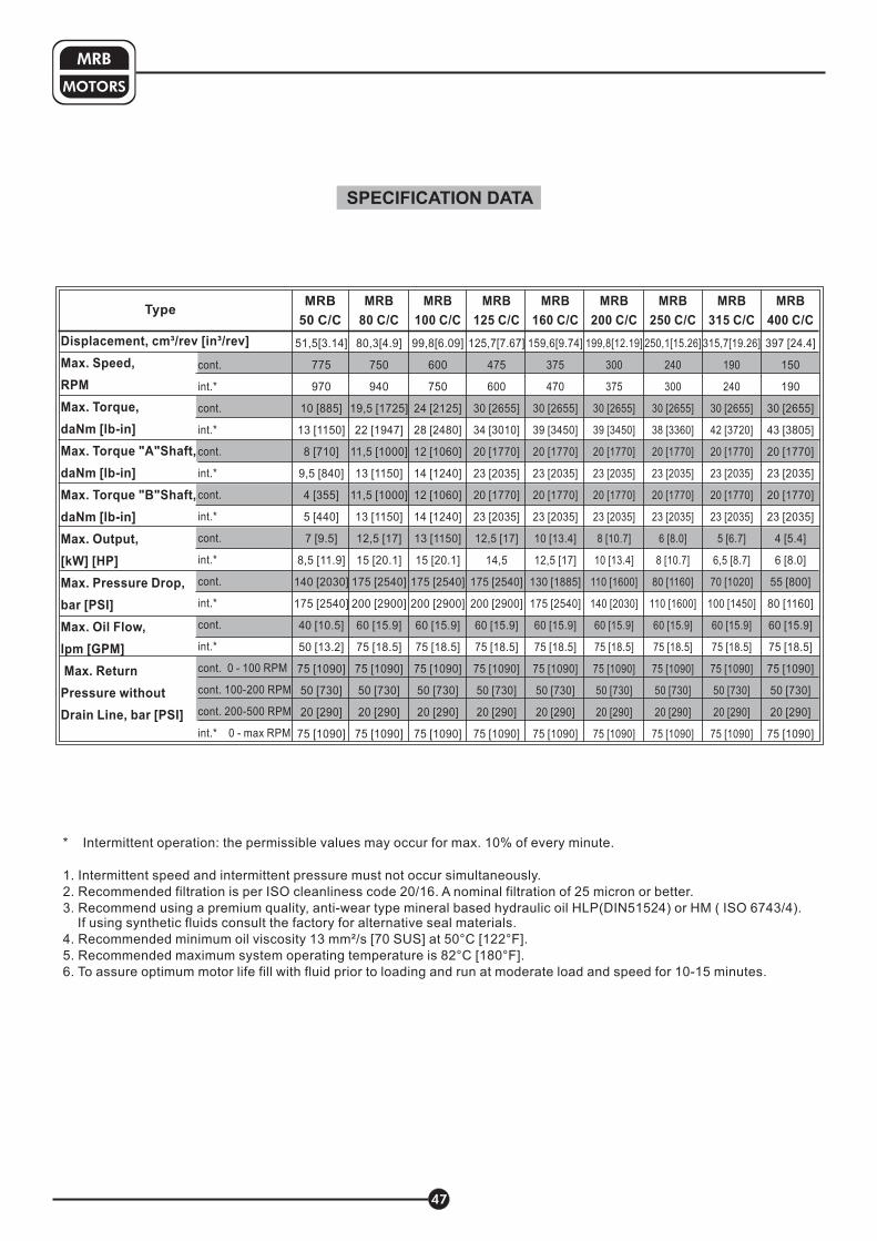
TypeMRB
100 C/C
cont.
int.*
100 RPM
int
cont.
int.*
cont.
int.*
cont.
int.*
cont.
int.*
cont.
int.*
cont.
int.*
cont. 0 -
cont. 100-200 RPM
cont. 200-500 RPM
.* 0 - max RPM
Displacement, cm³/rev [in³/rev]
Max. Speed,
RPM
Max. Torque,
daNm [lb-in]
Max. Torque "A"Shaft,
daNm [lb-in]
Max. Torque "B"Shaft,
daNm [lb-in]
Max. Output,
[kW] [HP]
Max. Pressure Drop,
bar [PSI]
Max. Oil Flow,
lpm [GPM]
Max. Return
Pressure without
Drain Line, bar [PSI]
51,5[3.14]
775
970
10 [885]
13 [1150]
8 [710]
9,5 [840]
4 [355]
5 [440]
7 [9.5]
8,5 [11.9]
140 [2030]
175 [2540]
40 [10.5]
50 [13.2]
75 [1090]
50 [730]
20 [290]
75 [1090]
MRB
50 C/C
80,3[4.9]
750
940
19,5 [1725]
22 [1947]
11,5 [1000]
13 [1150]
11,5 [1000]
13 [1150]
12,5 [17]
15 [20.1]
175 [2540]
200 [2900]
60 [15.9]
75 [18.5]
75 [1090]
50 [730]
20 [290]
75 [1090]
MRB
80 C/C
125,7[7.67]
475
600
30 [2655]
34 [3010]
20 [1770]
23 [2035]
20 [1770]
23 [2035]
12,5 [17]
14,5
175 [2540]
200 [2900]
60 [15.9]
75 [18.5]
75 [1090]
50 [730]
20 [290]
75 [1090]
MRB
125 C/C
159,6[9.74]
375
470
30 [2655]
39 [3450]
20 [1770]
23 [2035]
20 [1770]
23 [2035]
10 [13.4]
12,5 [17]
130 [1885]
175 [2540]
60 [15.9]
75 [18.5]
75 [1090]
50 [730]
20 [290]
75 [1090]
MRB
160 C/C
199,8[12.19]
300
375
30 [2655]
39 [3450]
20 [1770]
23 [2035]
20 [1770]
23 [2035]
8 [10.7]
10 [13.4]
110 [1600]
140 [2030]
60 [15.9]
75 [18.5]
75 [1090]
50 [730]
20 [290]
75 [1090]
MRB
200 C/C
250,1[15.26]
240
300
30 [2655]
38 [3360]
20 [1770]
23 [2035]
20 [1770]
23 [2035]
6 [8.0]
8 [10.7]
80 [1160]
110 [1600]
60 [15.9]
75 [18.5]
75 [1090]
50 [730]
20 [290]
75 [1090]
MRB
250 C/C
315,7[19.26]
190
240
30 [2655]
42 [3720]
20 [1770]
23 [2035]
20 [1770]
23 [2035]
5 [6.7]
6,5 [8.7]
70 [1020]
100 [1450]
60 [15.9]
75 [18.5]
75 [1090]
50 [730]
20 [290]
75 [1090]
MRB
315 C/C
397 [24.4]
150
190
30 [2655]
43 [3805]
20 [1770]
23 [2035]
20 [1770]
23 [2035]
4 [5.4]
6 [8.0]
55 [800]
80 [1160]
60 [15.9]
75 [18.5]
75 [1090]
50 [730]
20 [290]
75 [1090]
MRB
400 C/C
99,8[6.09]
600
750
24 [2125]
28 [2480]
12 [1060]
14 [1240]
12 [1060]
14 [1240]
13 [1150]
15 [20.1]
175 [2540]
200 [2900]
60 [15.9]
75 [18.5]
75 [1090]
50 [730]
20 [290]
75 [1090]
MOTORS
MRB
47
SPECIFICATION DATA
* Intermittent operation: the permissible values may occur for max. 10% of every minute.
1. Intermittent speed and intermittent pressure must not occur simultaneously.
2. Recommended filtration is per ISO cleanliness code 20/16. A nominal f ltration of 25 micron or better.
3. Recommend using a premium quality, anti-wear type mineral based hydraulic oil HM ( ISO 6743/4).If using synthetic fluids consult the factory for alternative seal materials.
4. Recommended minimum oil viscosity 13 mm²/s [70 SUS] at 50°C [122°F].
5. Recommended maximum system operating temperature is 82°C [180°F].
6. To assure optimum motor life fill with fluid prior to loading and run at moderate load and speed for 10-15 minutes.
i
HLP(DIN51524) or

MRB
1 2 5
Pos. 5 - Option (Paint)**
Pos. 6 - Design Series
omit - no Paint
- Painted
- Corrosion Protected Paint
P
PC
omit - Factory specified
ORDER CODE
NOTES:
* For other shaft extensions please contact with us.** Color at customer's request.
The hydraulic motors are mangano-phosphatized as standard.
PERMISSIBLE SHAFT LOADS
The load diagrams are valid for an average bearings life of 1600 hrs at 200 r.p.m. with mineral baselubricating containing antiwear additives (ref.ISO 281 (3.3)standard).The "A" curve gives the maximum static load affordable by the bearings.The "B" curve gives the radial load top limit without axial load of 200 daN.
Pos.2 - "A" Shaft Extensions*
- ø25 straight, Parallel key A8x7x30 DIN6885C
omit - none
- Low Speed ValveLSV
Pos. 4 - Special Features
Pos.3 - "B" Shaft Extensions*
3 4
/
6
- ø25 straight, Parallel key A8x7x30 DIN6885C
- 51,5 cm /rev [3.14 in /rev]
- 80,3 cm /rev [4.90 in /rev]
- 99,8 cm /rev [6.09 in /rev]
- 125,7 cm /rev [7.67 in /rev]
- 159,6 cm /rev [9.74 in /rev]
- 199,8 cm /rev [12.19 in /rev]
- 250,1 cm /rev [15.26 in /rev]
- 315,7 cm /rev [19.26 in /rev]
- 397,0 cm /rev [24.40 in /rev]
50
80
100
125
160
200
250
315
400
3 3
3 3
3 3
3 3
3 3
3 3
3 3
3 3
3 3
Pos.1 - Displacement code
MOTORS
MRB
48
100806040200-20-40 mm9070503010- 01- 03
43210 in3.52.51.50.5-0.5-1-1.5
0
250
500
750
1000
1250
1500
Pr
daN
B
A
470 lbs.210 daN
470 lbs.210 daN
Pa
Pr
Pradlbs
3000
2000
1000
2500
1500
500


![Www[1].nicepps.ro 6743 printemps_mouette](https://img.pdfslide.net/doc/110x75/55a1a81f1a28abf31e8b45f7/www1niceppsro-6743-printempsmouette.jpg)