Embed Size (px)
Citation preview
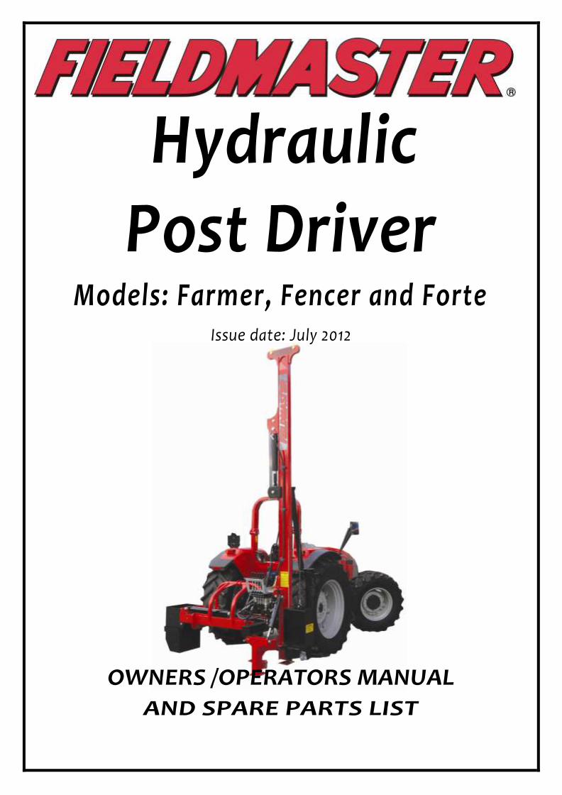
Hydraulic Post Driver
Models: Farmer, Fencer and Forte Issue date: July 2012
OWNERS /OPERATORS MANUAL
AND SPARE PARTS LIST

Thank you for choosing a quality FIELDMASTER product. Please pay careful attention to all instructions and safety warnings / notices. Spend sufficient time to familiarise yourself and other users with all set up, operation and maintenance instructions and recommendations to ensure your own safety and the efficient long term use of this implement. Always use genuine FIELDMASTER parts for any spares or replacement components needed in your maintenance or repairs.

S e t U p I n s t r u c t i o n s 1) Bolt on valve mounting handle bracket.
2) Bolt on hydraulic control bank (using fastenings provided) to the underside of valve mounting bracket.
3) FENCER & FARMER MODEL WITH HYDRAULIC OPTIONS - for safety these models are fitted with a transport/locking bar
over the side angle ram. Retain this in position and ensure there is oil in the system before lifting to the vertical position.
This ensures the mast will stay upright. Safety bar may now be removed.
FAILURE TO DO THIS MAY RESULT IN PERSONAL INJURY OR DAMAGE TO THE POST DRIVER.
4) Attach storage leg, lift mast to vertical position.
5) Attach the Post driver to tractor 3 Pt linkage.
6) Set the Hydraulic port relief on the hammer valve: (see detailed “setting the Port relief valve’ section below)
a) Before use, Check carefully all hydraulic connections are tight and have no oil leaks.
b) Check all 3 x wire rope grips (beside hyd. ram) are tight, and the hammer is securely fastened to the wire rope correctly.
7) Attach single QRC to tractor remote and dump hose to hydraulic return tank. Tank end of dump hose is fitted with a ¾
BSP female nut. Use this to attach to your oil return tank. Different size thread adaptors may be needed to suit your
tractor – a fitting pack of popular sizes is available from Fieldmaster: Part no 999005.01
NOTE: DO NOT use a QRC fitting on the return/ dump hose connection to the tractor.
Fitting a QRC (Quick release coupling) restricts the oil flow that has to be fed back into the tank. When the
hammer is dropped (while driving posts) the return/dump hose has to cope with a very high / fast flow of oil as the hammer is lowered under speed and requires a fast exit of a large amount of oil back to the tractor. Fitting of a QRC coupling will pressurize the return hose and most likely BURST under pressure. The return hose is specifically specified and fitted from the factory as a “LOW PRESSURE” return line (3/4”) and must have NO restriction back to the tractor.
8) OPEN CIRCUIT VALVE SYSTEM: – standard configuration If you have a “Closed Circuit System” on your tractor, a modification or upgrade fitting kit is required (Kit part number 116025.02) The standard configuration of the Rammer control valve is an ‘Open circuit’ system. If your tractor has a closed circuit hydraulic system, this means the oil system from the tractor requires a continuous
flow of oil to go through the Rammer valve and back to the tractor (as the tractor won’t have its own ‘bypass valve’ to send the oil back to the tank when the Rammer valve is not being used or is idle, (usually known as oil supply ON DEMAND which means that the tractor would only supply oil as the Rammer valve needs it). In this case, if your tractor has a closed circuit hydraulic system, you will need to fit the closed circuit modification kit (Part number 116025.02) which comprises of a small bung that is to be fitted into the port which is located underneath the hex head blanking plug on the side of the valve (see diagram next page). To fit this “Closed circuit plug” you will need to remove the outer hex blanking plug (as shown) and screw in the ¼” BSP Bung - right in, then replace the Hex blanking plug again.
This will now allow the ‘Tank Pressure’ to be the same as the ‘Input Pressure’ on the Rammer valve and work in conjunction with your ‘Closed circuit tractor hydraulic’ system.
9) Remove storage leg & bracket. Put to one side.
10) Place hammer on approximately 300mm high block, pallet, etc. Manoeuvre tractor & post driver over top of
hammer. (Locate mast in channel of hammer). Lower post driver on to hammer. Attach wire rope.

11) Gently lift and lower hammer up & down mast, using full ram stroke to purge air from hydraulics. After this is
achieved position hammer opposite handle bracket.
12) Slide post cap up to hammer & hook chain to hammer lug.
13) Refit storage leg bracket to base of mast to prevent post cap detaching.
14) Disconnect post cap chain. Raise hammer halfway up mast. Utilizing hydraulic control handle, allow hammer
to drop 300mm & release handle. Hammer should stop without "bounce" If hammer bounces, or "creeps” down
mast, adjust port relief valve.
Setting the Port Relief Valve: The Port relief valve adjusting screw is located on the underside of control
bank to the rear and right of hammer control slice (as pictured Item 2). To adjust, remove silver hex cap to expose slot
on top of valve. With flat screw driver, adjust in 1/8 turn increments clockwise until the correct setting is achieved.
The point in ‘setting’ the Port relief valve is in order to ensure a safe / cushioned hammer stop is in the hydraulic
system so that an abrupt / harsh ‘snap stop’ to the hydraulic line is not happening when the valve handle is returned
to centre when the hammer is falling down the mast. It is most likely that due to differing tractor hydraulic
pressures, flow rates, differing hammer weights etc that this adjusting will need to be fine tuned on initial fitment to
the tractor or the initial delivery of the machine.
a) Wind in to stop the hammer ‘creeping’ down mast (if it is open too much, the oil bypasses the spring loaded valve and the hammer will slowly slide down the mast)
b) Hammer stops with a soft cushioned stop rather than ‘bounce’. (if it stops with a bounce, the port relief is set too tight and will not be working)
Port relief valve
Pt No. 116025.03
Item 1 – Valve control lever kits (refer to parts dept for spares available) Handle ‘kit’ - pt number 116025.01
Item 2 – Port relief valve – Pt No 116025.03
Item 3 – Rear blanking plug to remove for closed circuit valve bung fitting (as per Instruction 8)
IMPORTANT TROUBLE SHOOTING NOTE REGARDING HAMMER CREEP OR PORT RELIEF SETTING PROBLEMS: If you find that the hammer continues to fall down even after the adjustments as detailed
above have been made, it is very likely that dirty or slightly contaminated hydraulic oil has damaged the fine ‘seat’ in the port relief valve. If this is damaged, your valve will need to be returned to Fieldmaster for re-seating of this port relief valve. This is NOT a warranty failure and will be caused by contamination in the hydraulic oil supply from the tractor (It only requires a small amount of contamination in the oil to cause a leakage!) Before this conclusion, try ‘flushing’ the oil or contamination through the port relief by jerking / pumping the port relief (stop / start the hammer with the port relief adjusted in and out and several other positions in order to try and flush any contamination lodged in between the fine port relief spring loaded seat) Failure to remedy this by doing this, will most likely mean that the port relief ‘seat’ has been scoured or slightly worn thus allowing oil to bypass – this will cause the hammer to slowly creep down the mast even when the valve handle is in spring centre (shut) position.
PREMATURE WIRE ROPE FAILURE OR SERIOUS INJURY COULD OCCUR IF RELIEF VALVE NOT SET CORRECTLY

Top Link and Side Tilt Extension brackets (extenders)
Your Fieldmaster Post Driver is built to suit industry standard Cat II Linkage dimensions. Should you find you cannot get enough top link or side-tilt angle, you can purchase a top link (or side tilt) ram extension bracket to give you further extension. These are available from Fieldmaster as follows:
Top link extension bracket Pt no. 998002.04
Side tilt extension bracket Pt no. 998401
Operating Instructions
1)After the tractor has been placed in position, put the hand brake on and place the gear selector in neutral, (or park, if the tractor has an automatic transmission).
2)Lower the Post Driver so that the legs are placed firmly on the ground.
3)Position adjustment to mast is done by using the adjusting screw link and top link, (or by hydraulic movement where hydraulic top link and side tilt rams are fitted).
4)Ensure the rammer is level by sighting the level sight glass provided on the machine.
5)Connect chain from the post cap to the prong on the hammer weight and raise the weight up by pulling the lever backward (see direction of arrow on valve).
6) Position the post cap so that the top of the post is directly underneath the post cap spike. Always position the post cap spike directly in the centre of the post.
7)Lower the weight so that the locator spike holds the post securely, and remove the chain from the hammer.
8)Always keep hands away from the post; stand to the side of the Post Driver when driving the post into the ground.
9)Start off with a few short strokes before using the full potential of the weight.
10)When the post has reached the desired height, attach the chain to the weight to pull the post cap off the post.
11)Raise the Post Driver with the weight in the lowered position before driving the tractor away.
IMPORTANT
a)Never move or adjust the machine until the hammer is completely lowered.
b)Never operate machine until level bubble is showing level position.
c)Keep well clear of the hammer when it is raised.
d)Do not stand below, or have any body part beneath the hammer when raised, even if it is stationary.

WARNING – SERIOUS INJURY HAZARD
Dismounting Instructions
1) Before disconnecting the Post Driver ensure that the weight has been lowered to base of the mast.
2) Position storage foot to the rear, and secure – Fit safety/transport bar over side tilt ram if supplied for added safety
3) Lower the Post Driver so that all three legs are touching the ground.
4) Disconnect the pressure hydraulic supply hose and then the return hose.
5) Slacken off the top link and remove the hitch pin. Ensure that the Post Driver is in a stable position.
6) Remove the hitch pins from the plough arms.
7) Check that nothing is connected to the tractor before driving off.
8) When Post Driver is disconnected from the tractor, do not leave free standing. Tie or chain mast up high to a
strong vertical member, as strong winds or an unintended knock could allow the post driver to fall over.
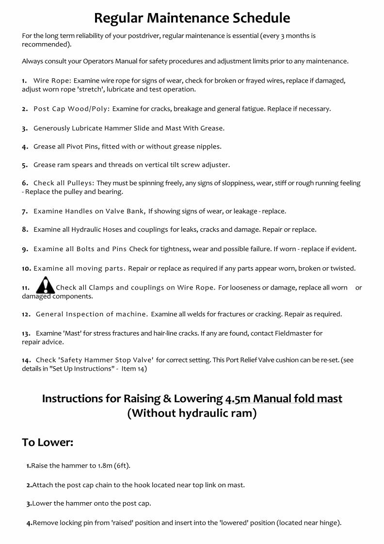
Regular Maintenance Schedule For the long term reliability of your postdriver, regular maintenance is essential (every 3 months is recommended).
Always consult your Operators Manual for safety procedures and adjustment limits prior to any maintenance.
1. Wire Rope: Examine wire rope for signs of wear, check for broken or frayed wires, replace if damaged, adjust worn rope 'stretch', lubricate and test operation.
2. Post Cap Wood/Poly: Examine for cracks, breakage and general fatigue. Replace if necessary.
3. Generously Lubricate Hammer Slide and Mast With Grease.
4. Grease all Pivot Pins, fitted with or without grease nipples.
5. Grease ram spears and threads on vertical tilt screw adjuster.
6. Check all Pulleys: They must be spinning freely, any signs of sloppiness, wear, stiff or rough running feeling - Replace the pulley and bearing.
7. Examine Handles on Valve Bank, If showing signs of wear, or leakage - replace.
8. Examine all Hydraulic Hoses and couplings for leaks, cracks and damage. Repair or replace.
9. Examine all Bolts and Pins Check for tightness, wear and possible failure. If worn - replace if evident.
10. Examine all moving parts. Repair or replace as required if any parts appear worn, broken or twisted.
11. Check all Clamps and couplings on Wire Rope. For looseness or damage, replace all worn or damaged components.
12. General Inspection of machine. Examine all welds for fractures or cracking. Repair as required.
13. Examine 'Mast' for stress fractures and hair-line cracks. If any are found, contact Fieldmaster for repair advice.
14. Check 'Safety Hammer Stop Valve' for correct setting. This Port Relief Valve cushion can be re-set. (see details in "Set Up Instructions" - Item 14)
Instructions for Raising & Lowering 4.5m Manual fold mast (Without hydraulic ram)
To Lower:
1.Raise the hammer to 1.8m (6ft).
2.Attach the post cap chain to the hook located near top link on mast.
3.Lower the hammer onto the post cap.
4. Remove locking pin from 'raised' position and insert into the 'lowered' position (located near hinge).

5.With your left fingertips push the rope towards the pulley located at the hinge whilst holding the operating lever for the hammer in lower position until the ram is fully retracted.
6.Still holding the wire rope into the pulley groove operate the hydraulics on the top link to tilt back until the ram hits its end stop.
7.The inertia of this movement will cause the top of the mast to fold over to the lowered position.
To Raise:
1.Raise the hammer approx. 600mm, to tighten rope, allowing mast to rise.
2.Insert locking pin into 'raised' position. You are ready to ram.
Instructions for Raising & Lowering 4.5m Hydraulic fold mast
To Lower: 1. Hammer should be in lowest position. 2. Ease locking pin tension with careful control of hydraulic ram 3. Remove mast-fold locking pin 4. Ensure mast is fully upright and tractor cab/rear window is clear of folding arc 5. Fold mast carefully keeping well clear of moving mast 6. Fit locking pin in transport position for safety and stability during transport/storage.
To Raise: 1. Remove locking pin from transport position 2. Ensure mast is full upright so mast arc is clear of tractor cab 3. Raise slowly ensuring wire rope is clear of obstruction to full height 4. Re-insert mast fold locking pin
WARNING – NEVER RAISE HAMMER OR OPERATE WITHOUT MAST LOCKING PIN IN PLACE
Manual ‘Supa Spike’ Rock Spike
(Not hydraulic extractor model)
Instructions for Use 1.Hook the post cap onto the hammer and raise them approximately 6 feet (1.8m) from the ground. 2.Lift the Supa Spike from out of the RHS cradle positioned on the side of the post driver leg.
3. Position the Supa Spike (with the triangle shaped hole facing towards the post driver) directly under the hammer with the spike point approximately 6 inches (150mm) away from the front of the post driver hammer slide flange.

4. Lower the hammer and post cap and carefully locate the post cap onto the top of the spike plate (taking care to see the point on the post cap locates into the triangle shaped hole on the top of the spike plate.
5. Remove the chain connecting the post cap from off the hammer hook.
6. Whilst keeping well away from the hammer starting with small strokes hit the spike into the ground with the hammer taking greater strokes once the spike has located correctly.
IMPORTANT! a) AT NO STAGE ANGLE OR TILT THE POST DRIVER WHILST THE SPIKE IS IN THE GROUND! This will bend the spike pin.
b)Ensure at all times the spike is being driven parallel with the post driver beam.
7. To remove the spike:
a) Lower the hammer onto the post cap
b) Hook the post cap chain to the hammer
c) Swing the Supa Spike chain over the top of the hammer (ensuring it is located behind the flange on top of the hammer)
d) Raise the hammer quickly several times up and down to give hard abrupt jerks which will release the spike from the ground.
8. Once the spike has been released from the hard ‘driven in' position it will easily lift away from out of the spike hole by raising the hammer.
9. Lower the hammer down moving the spike point away from the spike hole.
10. Release the Supa Spike chain from over the hammer and lift the spike back into the RHS cradle on the leg of the post driver.
Instructions for operating Hydraulic Rock Spike Extractor unit
1. Raise hammer and postcap carefully to just above rock spike height. 2. 90mm or 120mm spike is carried /stored in spike storage cradle. Remove storage chain to allow spike
to swing out of holder. 3. Release rockspike spring catch and pivot extractor plate into position central to hammer and
carefully locate spike in postcap receptacle. 4. Ensure plumb and spike alignment is checked then gently lower weight down onto postcap and
rockspike plate. 5. Lower extraction ram cradle to lowest point by operating rockspike valve control lever. IMPORTANT
– CRADLE / PLATE MUST BE AT END OF RAM (LOWEST POINT) BEFORE ANY HAMMER IMPACT BEGINS.
6. Hammer in rockspike pin starting with small strokes / low impact gradually increasing until pin is driven in to required depth.
7. Raise hammer & postcap to clearance height only. 8. Lift out spike by reversing extractor ram and return to spring locked storage position.
WARNING – ALWAYS KEEP HANDS & FEET CLEAR OF SPIKE / HAMMER IMPACT ZONE OR SERIOUS INJURY
MAY OCCUR!

FARMER, FENCER, CONTRACTOR & FORTE
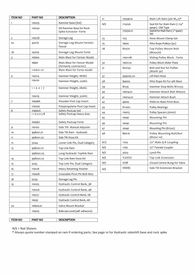
ITEM NO PART NO DESCRIPTION
1 116029 Rammer Base (Std)
116030 HD Rammer Base for Rock Spike Extractor -Forte
2 116028 Storage Leg
2a 44016 Storage Leg Mount Farmer/
Fencer
2b 24009 Storage Leg Mount Forte
3 116600 Main Mast for Farmer Model
116601 Main Mast for Fencer Model (formerly contractor)
116601-01 Main Mast for Forte model
6 116014 Hammer Weight, 18OKG
116016 Hammer Weight, 230KG
1 1 6 0 1 7 Hammer Weight, 280KG
116019 Hammer Weight, 320KG
7 11 6006A Wooden Post Cap Insert
116006 Polypropylene Post Cap Insert
8 11 6005 A Safety Postcap Std 1 1 6 0 0 5 B Safety Postcap Heavy duty
11 6005 C Safety Postcap Forte
9 116100 Side Tilt- Manual Adjuster
10 998001.01 Side Tilt Ram - Hydraulic
11 998001.02 Side Tilt Hose Kit
12 5044 Lower Link Pin, Dual Category
13 998002.01 Top Link Ram
998002.03 Long Hydraulic Toplink Ram
14 998002.02 Top Link Ram Hose Kit
15 5043 Top Link Pin, Dual Category
16 116018 Heavy Retaining Washer
17 116608 Greasable Pivot Pin Bolt M20
18 5039 Storage Leg Pin
19 116025 Hydraulic Control Bank, 3B
116026 Hydraulic Control Bank, 4B
116027 Hydraulic Control Bank, SB
116031 Hydraulic Control Bank, 6B
20 116600.01 Valve Mount Bracket
116605 Bulls eye Level (self- adhesive)
ITEM NO PART NO DESCRIPTION
21 715036.01 Main Lift Ram (4m Mast)*
N / S 715056 Seal Kit for Main Ram (1 1!4" spear) - Old Type
715056.01 Seal kit for Main Ram ( 2” spear) - Std
23 1173 Hose Mount Clamp Set
25 116012 Wire Rope Pulleys (9x)
28 B2070 Top Pulley Mount Bolt
(M20x70)
116011M Sliding Pulley Block - Forte
30 116011.01 Pulley Block Slider Plate
31 B20130 Bolt and Nut for Pullies (M20X1 30)
37 999005.02 Lift Ram Hose
38 840013 Wire Rope Kit For 4M Mast
39 B1235 Hammer Stop Bolts M12x35
40 116014.01 Hammer Attach Bolt M16x70
41 116014.02 Hammer Attach Bush
42 46002 Weld on Mast Pivot Boss
43 811062 Pulley Bearings
44 116013 Pulley Spacers (6mm)
45 10040 Mounting Pin
46 10040 Mounting Pin
47 10040 Mounting Pin (B1200)
48 B201 10 Pulley Mounting Bolt/Nut
(M20x1 10)
N / S 1164 1/2" Male Q-R Coupling
N/S 1166 1/2" Female Coupler
N/S 5603 Lynch Pin
N/S TLEXT/C Top Link Extension
N/S CCV/F Closed Centre Bung for Valve
N/S STEXT/C Side Tilt Extension Bracket
N/S = Not Shown. * Always quote number stamped on ram if ordering parts. See page 10 for Hydraulic sideshift base and rock spike

FENCER & FORTÉ 4.5 MTR FOLDING MAST PARTS
ITEM NO PART NO DESCRIPTION
4 44009 Folding mast base section
4a 116604 Forte Folding Mast Set
5 44010 Folding Mast Top Section
22 999005.02 Main ram hose
23 1173 Hose Clamp
24 10040 Main Ram Mount Pin
26 B20130 Pulley Mounting Bolt Nut (M20x1 30)
27 116602.02 Mast Fold Lock Pin
32 998001 .01 Hydraulic Ram (Mast Fold)
33 1998007 Hose Kit for Fold Ram
34 1177 Hose Clamp
35 715037.01 Main Ram (4.5 Mast)
71 5056.01 Ram Seal Kit
36 840015 Wire Rope Kit for 4.5m

HYDRAULIC SIDE SHIFT BASES
HYDRAULIC ROCKSPIKE EXTRACTOR
ITEM NO PART NO DESCRIPTION
1 A8245.01 Sideshift outer – 600
A8250.01 Sideshift outer – 300
A8248.01 Sideshift outer – 900
2 A8245.02 Sideshift inner - 600
A8250.02 Sideshift inner – 300
A8248.02 Sideshift inner – 900
A8245.03 Sideshift inner – 4 way 600
A8248.03 Sideshift inner – 4 way 900
3 A8245.04 Counterweight unit – 600
A8250.04 Counterweight unit – 300
A8248.04 Counterweight unit – 900
A8248.05 Aluminium tool tray – 900
4 998004.01 Sideshift ram – 600
998004.03 Sideshift ram – 300
998004.04 Sideshift ram – 900
5 10015 4 way MPS ram
5a 998005 4 way MPS hose kit
6 A8245.01L Storage/parking stand
ITEM NO PART NO DESCRIPTION
1 A8242 90mm rockspike pin
1a A8243 120mm rockspike pin
2 36005 Nylon ring for spike
3 34014/34015 Locking device/brackets
4 715038 Main extractor ram
4a 715038.01 Seal kit for extractor ram
5 715038.02 Ram seal only
6 116030 HD rockspike base unit
7 34008 Spike extractor plate – Fencer
7a 34002F Spike extractor plate – Forté
8 34005 Cylinder brace
9 3702130 Ram mount brackets – weld on
10 A8241 Hose kit for spike ram

Trouble Shooting
Problem Remedy
Hammer is slowly sliding down the mast by itself.
Cause:
a) Dirt on seat of port relief valve. Try clearing by jerking/operating lever several times. If ok, need to check tractor hydraulic oil and filter.
b) Port relief valve may be set too low Re-set port relief valve. Refer to (Oil by-passing valve). 'Set Up Instructions' – Point 14
c) Relief valve seat damaged due to oil Leaking port relief valve is due to contaminated contamination. dirty oil from tractor – this is not a warranty
problem. Please replace tractor oil filter.
Not Enough angle or side tilt. Some tractors are fitted with long/short linkage arms thus making the length of the top link ram insufficient - Contact your Fieldmaster dealer, as you can purchase a top link and side tilt extension bracket to enable extended length. (See pg 5)
Hammer stops / jerks abruptly when Port relief valve is not set correctly. handle is returned to centre. Refer to 'Set up Instructions' – point 14.