Embed Size (px)
Citation preview
HYDRAULIC PRESSES
Universal hydraulic presses for cold and hot forming
Straightening presses Special hydraulic presses for solid and sheet-metal forming
H a l f a c e n t u r y t r a d i t i o n i n d e s i g n a n d m a n u f a c t u r e o f f o r m i n g m a c h i n e s
ŽĎAS, a.s.Strojírenská 6591 71 Žďár nad SázavouCzech RepublicPhone: +420 566 64 2124Fax: +420 566 64 2871e-mail: [email protected]
H a l f a c e n t u r y t r a d i t i o n i n d e s i g n a n d m a n u f a c t u r e o f f o r m i n g m a c h i n e s
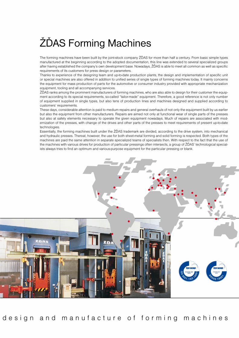
ŽĎAS Forming MachinesThe forming machines have been built by the joint-stock company ŽĎAS for more than half a century. From basic simple types manufactured at the beginning according to the adopted documentation, this line was extended to several specialized groups after having established the company’s own development base. Nowadays, ŽĎAS is able to meet all common as well as specific requirements of its customers for press design or parameters.Thanks to experience of the designing team and up-to-date production plants, the design and implementation of specific unit or special machines are also offered in addition to unified series of single types of forming machines today. It mainly concerns the equipment for mass production of parts for the automotive or consumer industry provided with appropriate mechanization equipment, tooling and all accompanying services.ŽĎAS ranks among the prominent manufacturers of forming machines, who are also able to design for their customer the equip-ment according to its special requirements, so-called “tailor-made” equipment. Therefore, a good reference is not only number of equipment supplied in single types, but also tens of production lines and machines designed and supplied according to customers’ requirements.These days, considerable attention is paid to medium repairs and general overhauls of not only the equipment built by us earlier but also the equipment from other manufacturers. Repairs are aimed not only at functional wear of single parts of the presses but also at safety elements necessary to operate the given equipment nowadays. Much of repairs are associated with mod-ernization of the presses, with change of the drives and other parts of the presses to meet requirements of present up-to-date technologies.Essentially, the forming machines built under the ŽĎAS trademark are divided, according to the drive system, into mechanical and hydraulic presses. Thereat, however, the use for both sheet-metal forming and solid forming is respected. Both types of the machines are paid the same attention in separate specialized teams of specialists then. With respect to the fact that the use of the machines with various drives for production of particular pressings often intersects, a group of ŽĎAS’ technological special-ists always tries to find an optimum and various-purpose equipment for the particular pressing or blank.
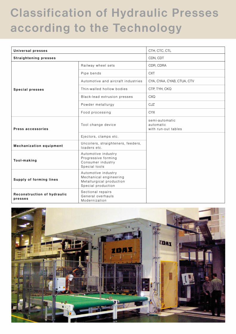
Classification of Hydraulic Presses according to the Technology
Universal presses CTH, CTC, CTL
CDN, CDTStraightening presses
Special presses
Rai lway wheel sets CDR, CDRA
Pipe bends CXT
Automot ive and a i rcraf t industr ies CYA, CYAA, CYAB, CTUA, CTV
Thin -wal led hol low bodies CTP, TYH, CKQ
Black- lead ext rus ion presses CXQ
Powder meta l lurgy CJZ
Food processing CYX
Tool change device
Ejectors , c lamps etc .
Uncoi lers , s t ra ighteners , feeders , loaders etc .
Automot ive industr yProgress ive formingConsumer industr ySpecia l tools
Automot ive industr yMechanical engineer ingMetal lurg ica l product ionSpecia l product ion
Sect ional repai rsGeneral overhaulsModernizat ion
semi -automat icautomat icwi th run-out tablesPress accessories
Mechanizat ion equipment
Tool -making
Supply of forming l ines
Reconstruct ion of hydraul ic presses
Principles of the drives of hydraulic presses manufactured by ŽĎAS, a.s. can be divided in two groups, i.e. water-emulsion and oil ones. The water-emulsion principle is mostly used for forging presses and the oil principle, both direct or combined, is used for forming hydraulic presses.
The company deals with the designs of industrial applications being operated with both hydraulic oil and water emulsion.ŽĎAS, a.s. being the prestigious manufacturer of forming machines for vari-ous industrial applications holds the unchanging philosophy of delivering its machines as complete and ready for use, including hydraulic, electronic and electric control systems.
The oil and hydraulic elements and hydraulic power units are mostly provid-ed by reputable world manufacturers, such as BOSCH REXROTH, OILGEAR-TOWLER, WEPUKO etc., while the control manifolds and all machine groups are designed and manufactured by ŽĎAS company using PC with the support of SW NX in 3D model.
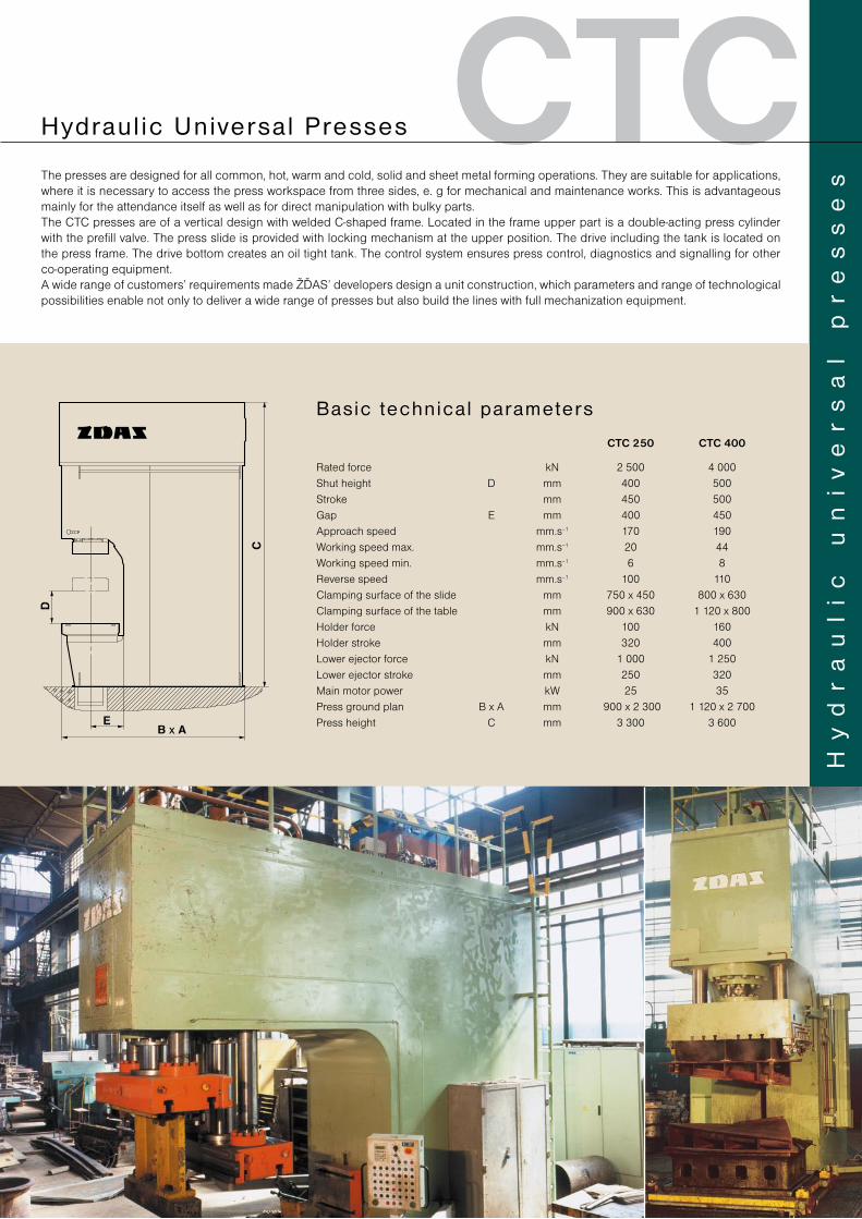
For big hydraulic systems, the accumulator drives are used with a water emul-sion (HFA fluid) used as working liquid. The accumulator drives being also called accumulator stations ensure drive even for more presses. The advantage of the above accumulator station is that it is designed for the average consumption of driven presses. The hydraulic-shock problem in the pipe at a long distance of the accumulator station from the presses has been solved by the incorpora-tion of an absorber in this piping. For accumulator drives, the hydraulic control and power elements of the same concept are used as those intended for oil drives. They only differ in the material used and minor design modifications. The great advantage in the development of this element base for water emul-sion hydraulics is the fact that the company is furnished with their own forging shop having suitable equipment, thus achieving a high productivity. The presses installed in the forging shop are connected to the central accumulator station and undergo regular machine modernization. Designing departments of ŽĎAS company have had a chance to make sure of new engineering solutions at any time in practice under heavy-duty conditions of a forging shop. In addition to the accumulator station, we can mention as an example the realized projects with accumulator drives, such as CKQ 630/220 press modernization, railway wheel-set line for BONATRANS Bohumín etc.
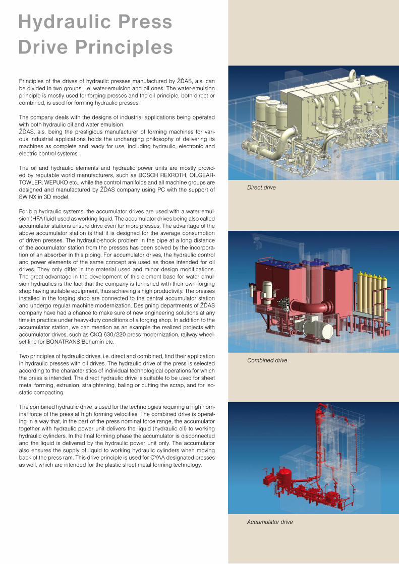
Two principles of hydraulic drives, i.e. direct and combined, find their applica tion in hydraulic presses with oil drives. The hydraulic drive of the press is se lec ted according to the characteristics of individual technological operations for which the press is intended. The direct hydraulic drive is suitable to be used for sheet metal forming, extrusion, straightening, baling or cutting the scrap, and for iso-static compacting.
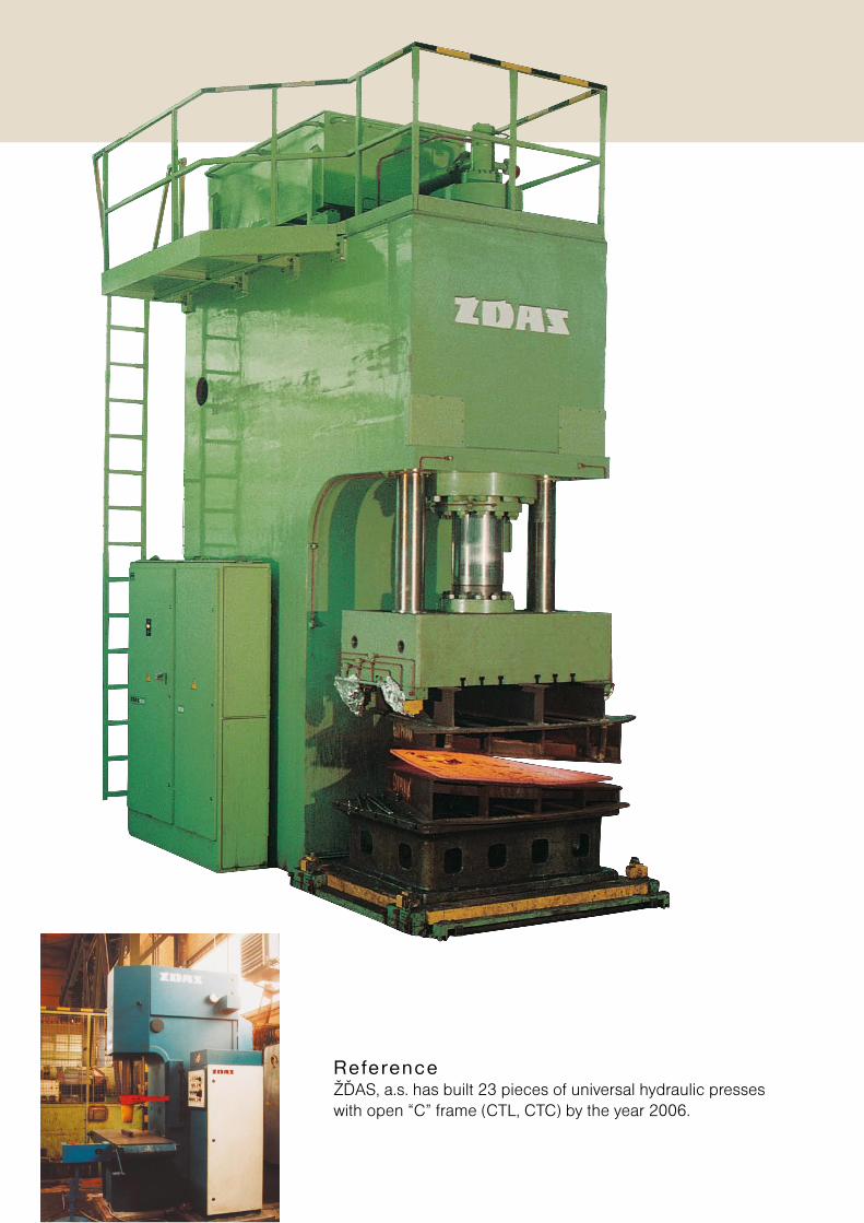
The combined hydraulic drive is used for the technologies requiring a high nom-inal force of the press at high forming velocities. The combined drive is operat-ing in a way that, in the part of the press nominal force range, the accumulator together with hydraulic power unit delivers the liquid (hydraulic oil) to working hydraulic cylinders. In the final forming phase the accumulator is disconnected and the liquid is delivered by the hydraulic power unit only. The accumulator also ensures the supply of liquid to working hydraulic cylinders when moving back of the press ram. This drive principle is used for CYAA designated presses as well, which are intended for the plastic sheet metal forming technology.
Hydraulic Press Drive Principles
Accumulator drive
Combined drive
Direct drive
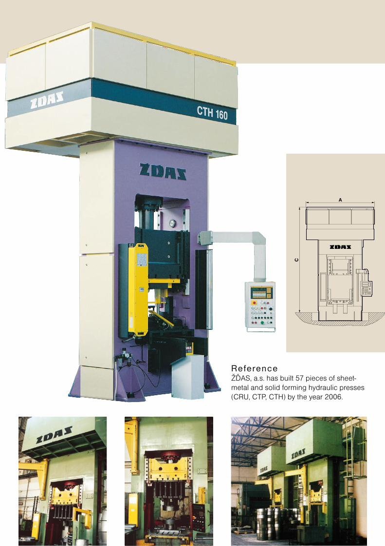
ReferenceŽĎAS, a.s. has built 23 pieces of universal hydraulic presses with open “C” frame (CTL, CTC) by the year 2006.
CTCThe presses are designed for all common, hot, warm and cold, solid and sheet metal forming operations. They are suitable for applica tions, where it is necessary to access the press workspace from three sides, e. g for mechanical and maintenance works. This is advantageous mainly for the attendance itself as well as for direct manipulation with bulky parts.The CTC presses are of a vertical design with welded C-shaped frame. Located in the frame upper part is a double-acting press cylinder with the prefill valve. The press slide is provided with locking mechanism at the upper position. The drive including the tank is located on the press frame. The drive bottom creates an oil tight tank. The control system ensures press control, diagnostics and signalling for other co-operating equipment.A wide range of customers’ requirements made ŽĎAS’ developers design a unit construction, which parameters and range of technological possibilities enable not only to deliver a wide range of presses but also build the lines with full mechanization equipment.
Hy
dr
au
li
c
un
iv
er
sa
l
pr
es
se
s
Hydraul ic Universa l Presses
CTC 250 CTC 400
Rated force kN 2 500 4 000Shut height D mm 400 500Stroke mm 450 500Gap E mm 400 450Approach speed mm.s–1 170 190Working speed max. mm.s–1 20 44Working speed min. mm.s–1 6 8Reverse speed mm.s–1 100 110Clamping surface of the slide mm 750 x 450 800 x 630Clamping surface of the table mm 900 x 630 1 120 x 800Holder force kN 100 160Holder stroke mm 320 400Lower ejector force kN 1 000 1 250Lower ejector stroke mm 250 320Main motor power kW 25 35Press ground plan B x A mm 900 x 2 300 1 120 x 2 700Press height C mm 3 300 3 600
Basic technica l parameters
ReferenceŽĎAS, a.s. has built 57 pieces of sheet-metal and solid forming hydraulic presses (CRU, CTP, CTH) by the year 2006.
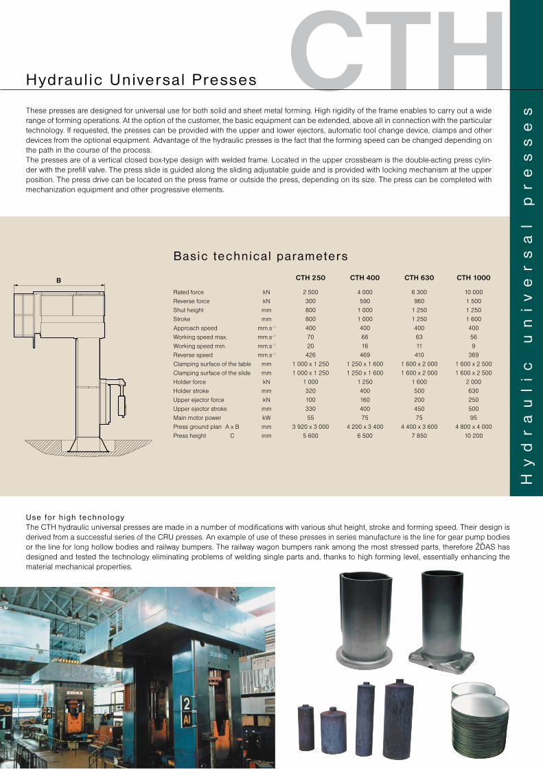
CTHThese presses are designed for universal use for both solid and sheet metal forming. High rigidity of the frame enables to carry out a wide range of forming operations. At the option of the customer, the basic equipment can be extended, above all in connection with the particular technology. If requested, the presses can be provided with the upper and lower ejectors, automatic tool change device, clamps and other devices from the optional equipment. Advantage of the hydraulic presses is the fact that the forming speed can be changed depending on the path in the course of the process.The presses are of a vertical closed box-type design with welded frame. Located in the upper crossbeam is the double-acting press cylin-der with the prefill valve. The press slide is guided along the sliding adjustable guide and is provided with locking mechanism at the upper position. The press drive can be located on the press frame or outside the press, depending on its size. The press can be completed with mechanization equipment and other progressive elements.
CTH 250 CTH 400 CTH 630 CTH 1000
Rated force kN 2 500 4 000 6 300 10 000Reverse force kN 300 590 960 1 500Shut height mm 800 1 000 1 250 1 250Stroke mm 800 1 000 1 250 1 600Approach speed mm.s–1 400 400 400 400Working speed max. mm.s–1 70 66 63 56Working speed min. mm.s–1 20 16 11 9Reverse speed mm.s–1 426 469 410 369Clamping surface of the table mm 1 000 x 1 250 1 250 x 1 600 1 600 x 2 000 1 600 x 2 500Clamping surface of the slide mm 1 000 x 1 250 1 250 x 1 600 1 600 x 2 000 1 600 x 2 500Holder force kN 1 000 1 250 1 600 2 000Holder stroke mm 320 400 500 630Upper ejector force kN 100 160 200 250Upper ejector stroke mm 330 400 450 500Main motor power kW 55 75 75 95Press ground plan A x B mm 3 920 x 3 000 4 200 x 3 400 4 400 x 3 600 4 800 x 4 000Press height C mm 5 600 6 500 7 850 10 200
Basic technica l parameters
Hy
dr
au
li
c
un
iv
er
sa
l
pr
es
se
s
Hydraul ic Universa l Presses
Use for h igh technologyThe CTH hydraulic universal presses are made in a number of modifications with various shut height, stroke and forming speed. Their design is derived from a successful series of the CRU presses. An example of use of these presses in series manufacture is the line for gear pump bodies or the line for long hollow bodies and railway bumpers. The railway wagon bumpers rank among the most stressed parts, therefore ŽĎAS has designed and tested the technology eliminating problems of welding single parts and, thanks to high forming level, essentially enhancing the material mechanical properties.
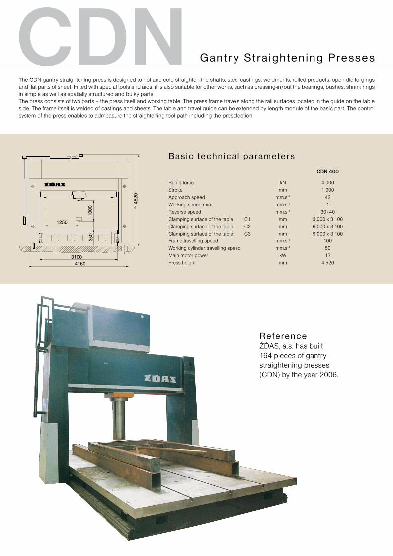
CDNThe CDN gantry straightening press is designed to hot and cold straighten the shafts, steel castings, weldments, rolled products, open-die forging s and flat parts of sheet. Fitted with special tools and aids, it is also suitable for other works, such as pressing-in/out the bearings, bushes, shrink rings in simple as well as spatially structured and bulky parts.The press consists of two parts – the press itself and working table. The press frame travels along the rail surfaces located in the guide on the table side. The frame itself is welded of castings and sheets. The table and travel guide can be extended by length module of the basic part. The control system of the press enables to admeasure the straightening tool path including the preselection.
Gantr y S tra ightening Presses
CDN 400
Rated force kN 4 000Stroke mm 1 000Approach speed mm.s–1 42Working speed min. mm.s–1 1Reverse speed mm.s–1 30÷40Clamping surface of the table C1 mm 3 000 x 3 100Clamping surface of the table C2 mm 6 000 x 3 100Clamping surface of the table C3 mm 9 000 x 3 100Frame travelling speed mm.s–1 100Working cylinder travelling speed mm.s–1 50Main motor power kW 12Press height mm 4 520
Basic technica l parameters
ReferenceŽĎAS, a.s. has built 164 pieces of gantry straightening presses (CDN) by the year 2006.
CDT CDT 1000
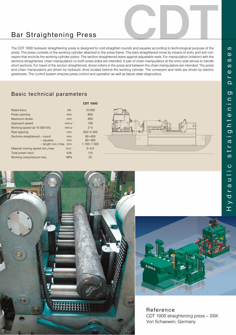
Rated force kN 10 000 Press opening mm 800 Maximum stroke mm 850 Approach speed mm.s–1 100 Working speed (at 10 000 kN) mm.s–1 2÷5 Rest spacing mm 500÷2 200 Sections straightened – round mm 90÷400
– squares mm 90÷400 – length min./max. mm 1 700÷7 000
Material moving speed min./max. m.s–1 0÷0,5 Total power input kVA 110 Working overpressure max. MPa 25
Basic technica l parameters
Hy
dr
au
lic
s
tr
aig
ht
en
ing
p
re
ss
esThe CDT 1000 hydraulic straightening press is designed to cold straighten rounds and squares according to technological purpose of the
press. The press consists of the working cylinder attached to the press frame. The bars straightened move by means of entry and exit con-veyers that encircle the working cylinder piston. The section straightened leans against adjustable rests. For manipulation (rotation) with the sections straightened, chain manipulators on both press sides are intended. A pair of chain manipulators at the entry side serves to handle short sections. For travel of the section straightened, driven rollers in the press and between the chain manipulators are intended. The press and chain manipulators are driven by hydraulic drive located behind the working cylinder. The conveyers and rests are driven by electric gearboxes. The control system ensures press control and operation as well as failure state diagnostics.
Bar S tra ightening Press
ReferenceCDT 1000 straightening press – SSK Von Schaewen, Germany
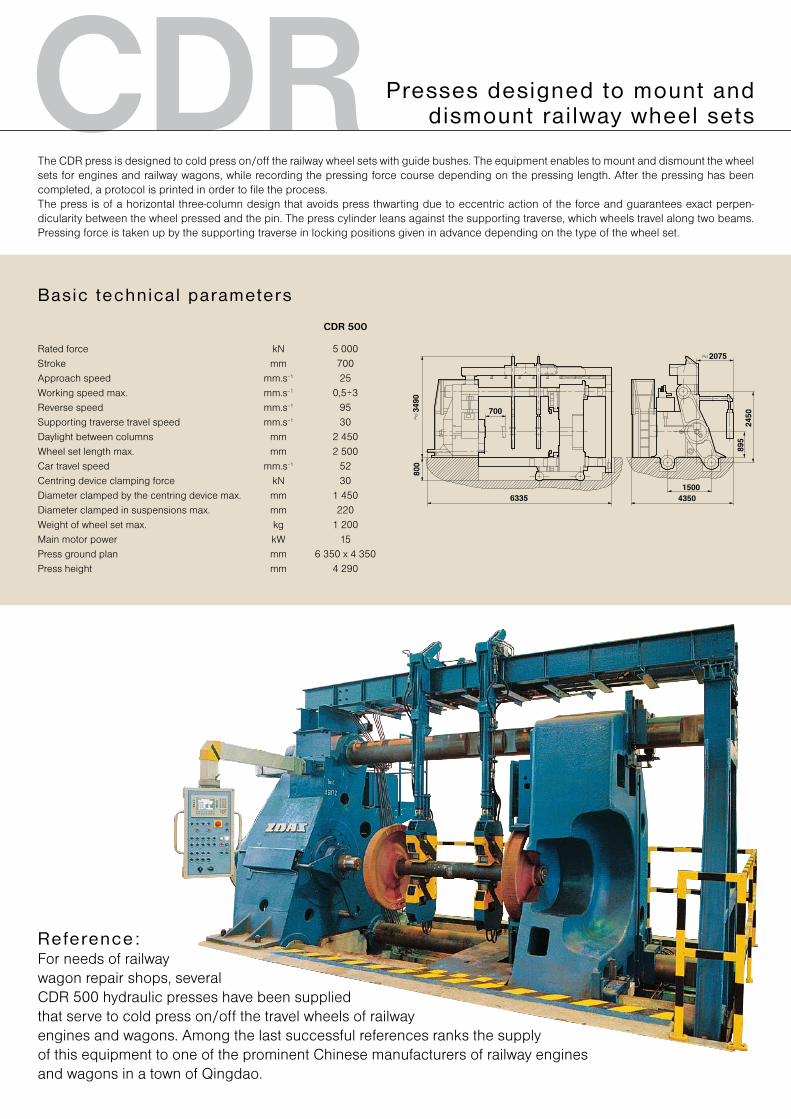
CDRThe CDR press is designed to cold press on/off the railway wheel sets with guide bushes. The equipment enables to mount and dismount the wheel sets for engines and railway wagons, while recording the pressing force course depending on the pressing length. After the pressing has been completed, a protocol is printed in order to file the process.The press is of a horizontal three-column design that avoids press thwarting due to eccentric action of the force and guarantees exact perpen-dicularity between the wheel pressed and the pin. The press cylinder leans against the supporting traverse, which wheels travel along two beams. Pressing force is taken up by the supporting traverse in locking positions given in advance depending on the type of the wheel set.
CDR 500
Rated force kN 5 000Stroke mm 700Approach speed mm.s–1 25Working speed max. mm.s–1 0,5÷3Reverse speed mm.s–1 95Supporting traverse travel speed mm.s–1 30Daylight between columns mm 2 450Wheel set length max. mm 2 500Car travel speed mm.s–1 52Centring device clamping force kN 30Diameter clamped by the centring device max. mm 1 450Diameter clamped in suspensions max. mm 220Weight of wheel set max. kg 1 200Main motor power kW 15Press ground plan mm 6 350 x 4 350Press height mm 4 290
Basic technica l parameters
Presses designed to mount and dismount rai lway wheel sets
Reference:For needs of railway wagon repair shops, several CDR 500 hydraulic presses have been supplied that serve to cold press on/off the travel wheels of railway engines and wagons. Among the last successful references ranks the supply of this equipment to one of the prominent Chinese manufacturers of railway engines and wagons in a town of Qingdao.
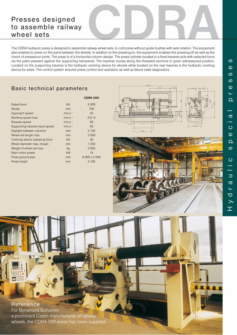
CDRAThe CDRA hydraulic press is designed to assemble railway wheel sets, to cold press without guide bushes with axle rotation. The equipment also enables to press on the parts between the wheels. In addition to the pressing-on, the equipment enables the pressing-off as well as the check of pressed-on joints. The press is of a horizontal column design. The press cylinder located in a fixed traverse acts with selected force via the parts pressed against the supporting transverse. The traverse moves along the threaded anchors to given admeasured position. Located on the supporting traverse is the hydraulic centring device for wheels while located on the rear traverse is the hydraulic centring device for axles. The control system ensures press control and operation as well as failure state diagnostics.
Hy
dr
au
li
c
sp
ec
ia
l
pr
es
se
s
P resses designed to assemble ra i lway wheel sets
CDRA 500
Rated force kN 5 000Stroke mm 700Approach speed mm.s–1 25Working speed max. mm.s–1 0,5÷3Reverse speed mm.s–1 95Supporting traverse travel speed mm.s–1 30Daylight between columns mm 2 100Wheel set length max. mm 2 650Centring device clamping force kN 30Wheel diameter max. (tread) mm 1 250Weight of wheel set max. kg 3 500Main motor power kW 15Press ground plan mm 8 900 x 2 000Press height mm 3 100
Basic technica l parameters
ReferenceFor Bonatrans Bohumín, a prominent Czech manufacturer of railway wheels, the CDRA 500 press has been supplied.
CXT
CXT 120
Rated force kN 1 200Working stroke mm 5 000Working speed mm.s–1 2÷84Working speed at max. force mm.s–1 40Reverse speed mm.s–1 800Auxiliary car force kN 68Auxiliary car stroke mm 5 500Auxiliary car speed mm.s–1 800Auxiliary car reverse speed mm.s–1 800Jaw opening mm 160Clamping force kN 50Working overpressure MPa 32
Basic technica l parameters
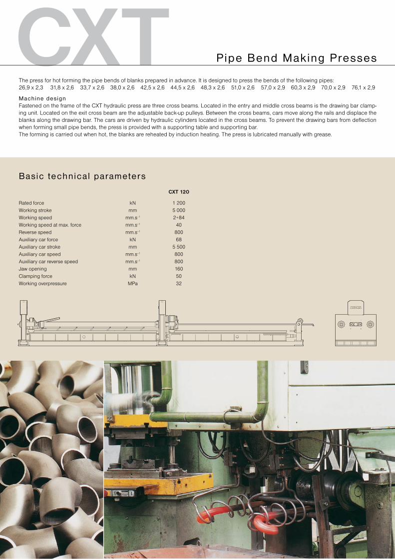
The press for hot forming the pipe bends of blanks prepared in advance. It is designed to press the bends of the following pipes: 26,9 x 2,3 31,8 x 2,6 33,7 x 2,6 38,0 x 2,6 42,5 x 2,6 44,5 x 2,6 48,3 x 2,6 51,0 x 2,6 57,0 x 2,9 60,3 x 2,9 70,0 x 2,9 76,1 x 2,9
Machine designFastened on the frame of the CXT hydraulic press are three cross beams. Located in the entry and middle cross beams is the drawing bar clamp-ing unit. Located on the exit cross beam are the adjustable back-up pulleys. Between the cross beams, cars move along the rails and displace the blanks along the drawing bar. The cars are driven by hydraulic cylinders located in the cross beams. To prevent the drawing bars from deflection when forming small pipe bends, the press is provided with a supporting table and supporting bar.The forming is carried out when hot, the blanks are reheated by induction heating. The press is lubricated manually with grease.
Pipe Bend Making Presses
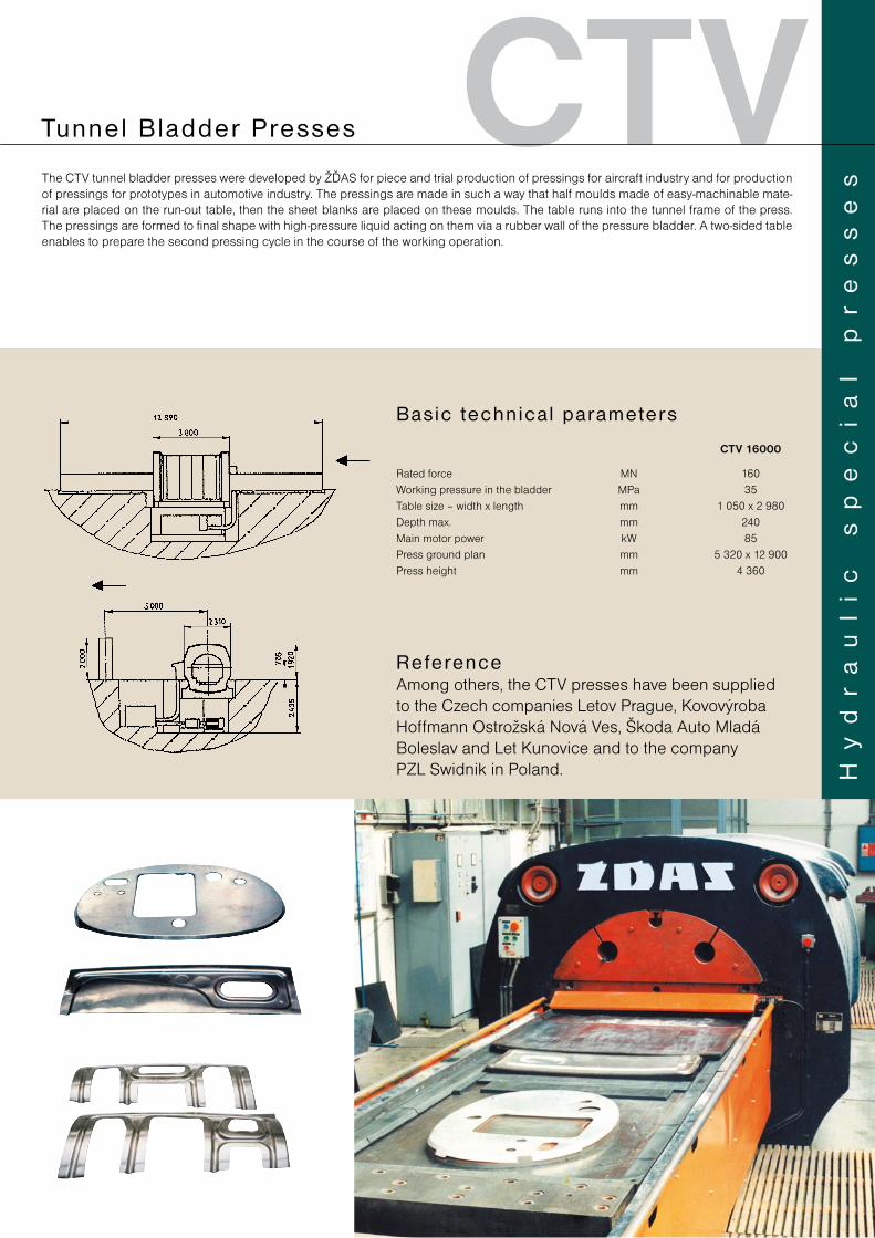
CTVThe CTV tunnel bladder presses were developed by ŽĎAS for piece and trial production of pressings for aircraft industry and for production of pressings for prototypes in automotive industry. The pressings are made in such a way that half moulds made of easy-machinable mate-rial are placed on the run-out table, then the sheet blanks are placed on these moulds. The table runs into the tunnel frame of the press. The pressings are formed to final shape with high-pressure liquid acting on them via a rubber wall of the pressure bladder. A two-sided table enables to prepare the second pressing cycle in the course of the working operation.
Tunnel Bladder Presses
CTV 16000
Rated force MN 160Working pressure in the bladder MPa 35Table size – width x length mm 1 050 x 2 980Depth max. mm 240Main motor power kW 85Press ground plan mm 5 320 x 12 900Press height mm 4 360
Basic technica l parameters
ReferenceAmong others, the CTV presses have been supplied to the Czech companies Letov Prague, Kovovýroba Hoffmann Ostrožská Nová Ves, Škoda Auto Mladá Boleslav and Let Kunovice and to the company PZL Swidnik in Poland. H
yd
ra
ul
ic
s
pe
ci
al
p
re
ss
es
CYA Insu la t ing Pad Making Presses
CYA 500
Rated force kN 5 000Stroke mm 1 600Shut height mm 200Approach speed mm.s–1 600Working speed max. mm.s–1 11Working speed min. mm.s–1 1÷7Reverse speed mm.s–1 600Clamping surface of the slide a stolu mm 2 800 x 1 800Main motor power kW 55Press ground plan A x B mm 4 600 x 2 800Press height C mm 6 930
Basic technica l parameters
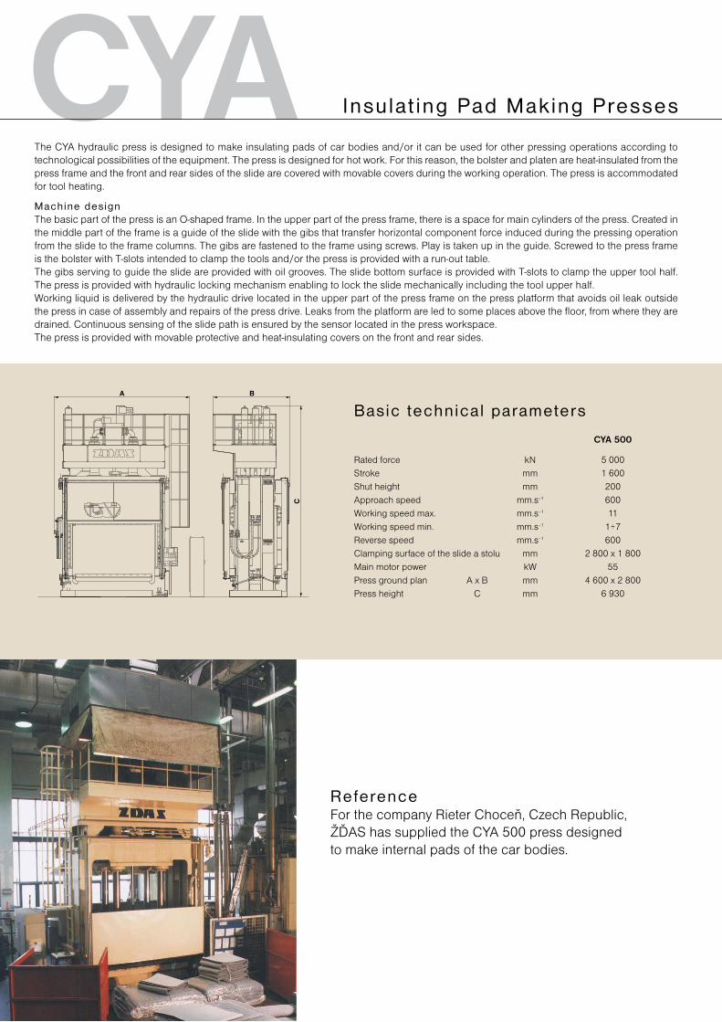
The CYA hydraulic press is designed to make insulating pads of car bodies and/or it can be used for other pressing operations according to technological possibilities of the equipment. The press is designed for hot work. For this reason, the bolster and platen are heat-insulated from the press frame and the front and rear sides of the slide are covered with movable covers during the working operation. The press is accommodated for tool heating.
Machine designThe basic part of the press is an O-shaped frame. In the upper part of the press frame, there is a space for main cylinders of the press. Created in the middle part of the frame is a guide of the slide with the gibs that transfer horizontal component force induced during the pressing operation from the slide to the frame columns. The gibs are fastened to the frame using screws. Play is taken up in the guide. Screwed to the press frame is the bolster with T-slots intended to clamp the tools and/or the press is provided with a run-out table.The gibs serving to guide the slide are provided with oil grooves. The slide bottom surface is provided with T-slots to clamp the upper tool half. The press is provided with hydraulic locking mechanism enabling to lock the slide mechanically including the tool upper half.Working liquid is delivered by the hydraulic drive located in the upper part of the press frame on the press platform that avoids oil leak outside the press in case of assembly and repairs of the press drive. Leaks from the platform are led to some places above the floor, from where they are drained. Continuous sensing of the slide path is ensured by the sensor located in the press workspace.The press is provided with movable protective and heat-insulating covers on the front and rear sides.
ReferenceFor the company Rieter Choceň, Czech Republic, ŽĎAS has supplied the CYA 500 press designed to make internal pads of the car bodies.
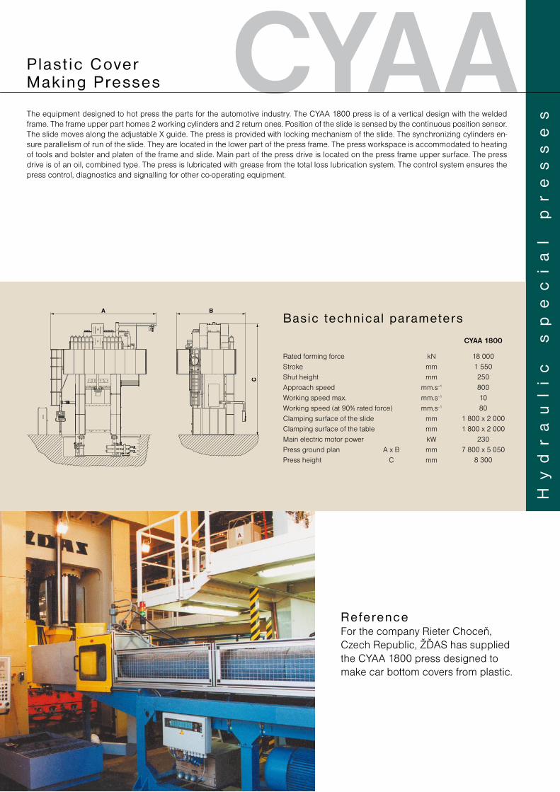
CYAAPlas t ic Cover Making Presses
The equipment designed to hot press the parts for the automotive industry. The CYAA 1800 press is of a vertical design with the welded frame. The frame upper part homes 2 working cylinders and 2 return ones. Position of the slide is sensed by the continuous position sensor. The slide moves along the adjustable X guide. The press is provided with locking mechanism of the slide. The synchronizing cylinders en-sure parallelism of run of the slide. They are located in the lower part of the press frame. The press workspace is accommodated to heating of tools and bolster and platen of the frame and slide. Main part of the press drive is located on the press frame upper surface. The press drive is of an oil, combined type. The press is lubricated with grease from the total loss lubrication system. The control system ensures the press control, diagnostics and signalling for other co-operating equipment.
CYAA 1800
Rated forming force kN 18 000Stroke mm 1 550Shut height mm 250Approach speed mm.s–1 800Working speed max. mm.s–1 10Working speed (at 90% rated force) mm.s–1 80Clamping surface of the slide mm 1 800 x 2 000Clamping surface of the table mm 1 800 x 2 000Main electric motor power kW 230Press ground plan A x B mm 7 800 x 5 050Press height C mm 8 300
Basic technica l parameters
Hy
dr
au
li
c
sp
ec
ia
l
pr
es
se
s
ReferenceFor the company Rieter Choceň, Czech Republic, ŽĎAS has supplied the CYAA 1800 press designed to make car bottom covers from plastic.
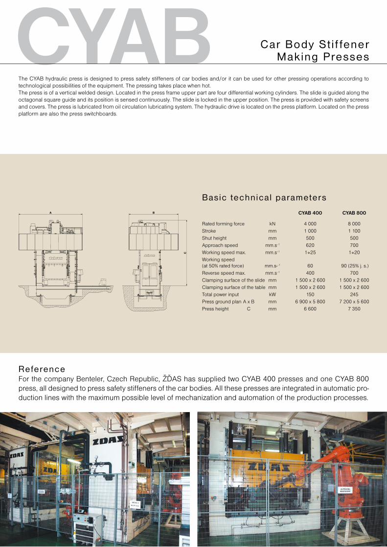
CYAB Car Body St i f fener Making Presses
The CYAB hydraulic press is designed to press safety stiffeners of car bodies and/or it can be used for other pressing operations according to technological possibilities of the equipment. The pressing takes place when hot.The press is of a vertical welded design. Located in the press frame upper part are four differential working cylinders. The slide is guided along the octagonal square guide and its position is sensed continuously. The slide is locked in the upper position. The press is provided with safety screens and covers. The press is lubricated from oil circulation lubricating system. The hydraulic drive is located on the press platform. Located on the press platform are also the press switchboards.
CYAB 400 CYAB 800
Rated forming force kN 4 000 8 000Stroke mm 1 000 1 100Shut height mm 500 500Approach speed mm.s–1 620 700Working speed max. mm.s–1 1÷25 1÷20Working speed (at 50% rated force) mm.s-–1 60 90 (25% j. s.)Reverse speed max. mm.s–1 400 700Clamping surface of the slide mm 1 500 x 2 600 1 500 x 2 600Clamping surface of the table mm 1 500 x 2 600 1 500 x 2 600Total power input kW 150 245Press ground plan A x B mm 6 900 x 5 800 7 200 x 5 600Press height C mm 6 600 7 350
Basic technica l parameters
ReferenceFor the company Benteler, Czech Republic, ŽĎAS has supplied two CYAB 400 presses and one CYAB 800 press, all designed to press safety stiffeners of the car bodies. All these presses are integrated in automatic pro-duction lines with the maximum possible level of mechanization and automation of the production processes.
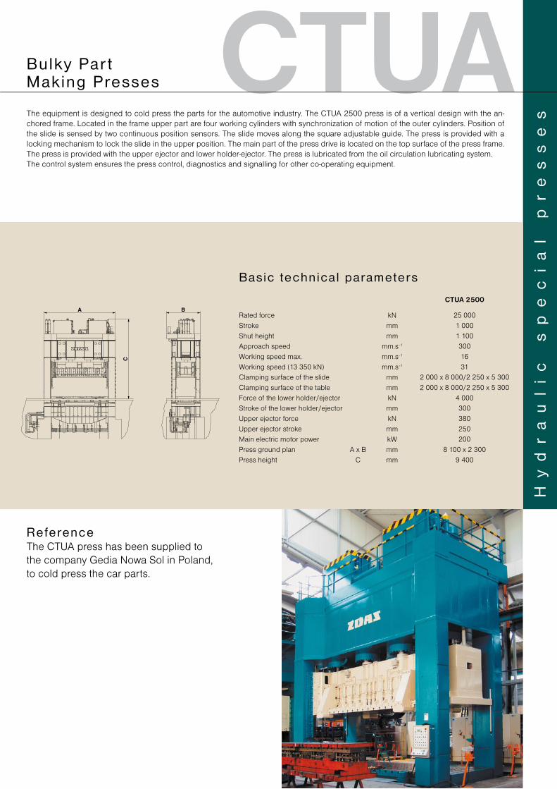
CTUA
CTUA 2500
Rated force kN 25 000Stroke mm 1 000Shut height mm 1 100Approach speed mm.s–1 300Working speed max. mm.s–1 16Working speed (13 350 kN) mm.s–1 31Clamping surface of the slide mm 2 000 x 8 000/2 250 x 5 300Clamping surface of the table mm 2 000 x 8 000/2 250 x 5 300Force of the lower holder/ejector kN 4 000Stroke of the lower holder/ejector mm 300Upper ejector force kN 380Upper ejector stroke mm 250Main electric motor power kW 200Press ground plan A x B mm 8 100 x 2 300Press height C mm 9 400
Basic technica l parameters
The equipment is designed to cold press the parts for the automotive industry. The CTUA 2500 press is of a vertical design with the an-chored frame. Located in the frame upper part are four working cylinders with synchronization of motion of the outer cylinders. Position of the slide is sensed by two continuous position sensors. The slide moves along the square adjustable guide. The press is provided with a locking mechanism to lock the slide in the upper position. The main part of the press drive is located on the top surface of the press frame. The press is provided with the upper ejector and lower holder-ejector. The press is lubricated from the oil circulation lubricating system.The control system ensures the press control, diagnostics and signalling for other co-operating equipment.
Hy
dr
au
li
c
sp
ec
ia
l
pr
es
se
s
Bu lky Par t Making Presses
ReferenceThe CTUA press has been supplied to the company Gedia Nowa Sol in Poland, to cold press the car parts.
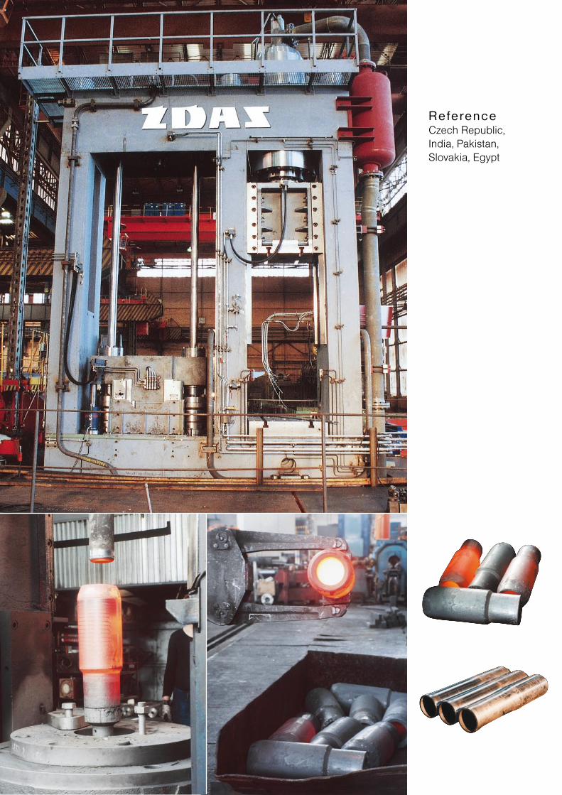
ReferenceCzech Republic, India, Pakistan, Slovakia, Egypt
TYHCKQ
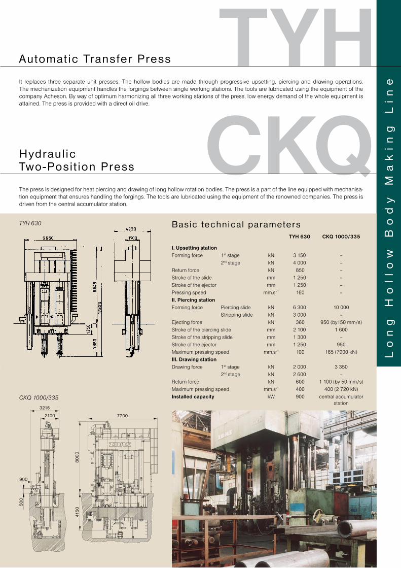
TYH 630
CKQ 1000/335
TYH 630 CKQ 1000/335
I. Upsetting stationForming force 1st stage kN 3 150 – 2nd stage kN 4 000 – Return force kN 850 –Stroke of the slide mm 1 250 –Stroke of the ejector mm 1 250 – Pressing speed mm.s–1 160 –II. Piercing stationForming force Piercing slide kN 6 300 10 000 Stripping slide kN 3 000 –Ejecting force kN 360 950 (by150 mm/s)Stroke of the piercing slide mm 2 100 1 600Stroke of the stripping slide mm 1 300 –Stroke of the ejector mm 1 250 950Maximum pressing speed mm.s–1 100 165 (7900 kN)III. Drawing stationDrawing force 1st stage kN 2 000 3 350 2nd stage kN 2 600 –Return force kN 600 1 100 (by 50 mm/s)Maximum pressing speed mm.s–1 400 400 (2 720 kN)Installed capacity kW 900 central accumulator station
Basic technica l parameters
Lo
ng
H
ol
lo
w
Bo
dy
M
ak
in
g
Li
neIt replaces three separate unit presses. The hollow bodies are made through progressive upsetting, piercing and drawing operations.
The mechanization equipment handles the forgings between single working stations. The tools are lubricated using the equipment of the company Acheson. By way of optimum harmonizing all three working stations of the press, low energy demand of the whole equipment is attained. The press is provided with a direct oil drive.
Automat ic Transfer Press
The press is designed for heat piercing and drawing of long hollow rotation bodies. The press is a part of the line equipped with mechanisa-tion equipment that ensures handling the forgings. The tools are lubricated using the equipment of the renowned companies. The press is driven from the central accumulator station.
Hydraul ic Two-Posi t ion Press
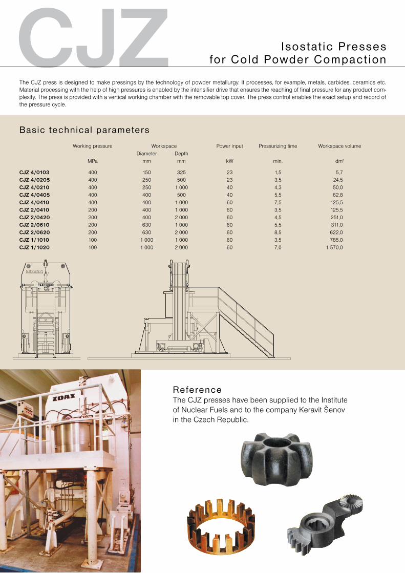
CJZThe CJZ press is designed to make pressings by the technology of powder metallurgy. It processes, for example, metals, carbides, ceramics etc. Material processing with the help of high pressures is enabled by the intensifier drive that ensures the reaching of final pressure for any product com-plexity. The press is provided with a vertical working chamber with the removable top cover. The press control enables the exact setup and record of the pressure cycle.
Isos tat ic Presses for Cold Powder Compact ion
ReferenceThe CJZ presses have been supplied to the Institute of Nuclear Fuels and to the company Keravit Šenov in the Czech Republic.
Working pressure Workspace Power input Pressurizing time Workspace volume Diameter Depth MPa mm mm kW min. dm3
CJZ 4/0103 400 150 325 23 1,5 5,7CJZ 4/0205 400 250 500 23 3,5 24,5CJZ 4/0210 400 250 1 000 40 4,3 50,0CJZ 4/0405 400 400 500 40 5,5 62,8CJZ 4/0410 400 400 1 000 60 7,5 125,5CJZ 2/0410 200 400 1 000 60 3,5 125,5CJZ 2/0420 200 400 2 000 60 4,5 251,0CJZ 2/0610 200 630 1 000 60 5,5 311,0CJZ 2/0620 200 630 2 000 60 8,5 622,0CJZ 1/1010 100 1 000 1 000 60 3,5 785,0CJZ 1/1020 100 1 000 2 000 60 7,0 1 570,0
Basic technica l parameters
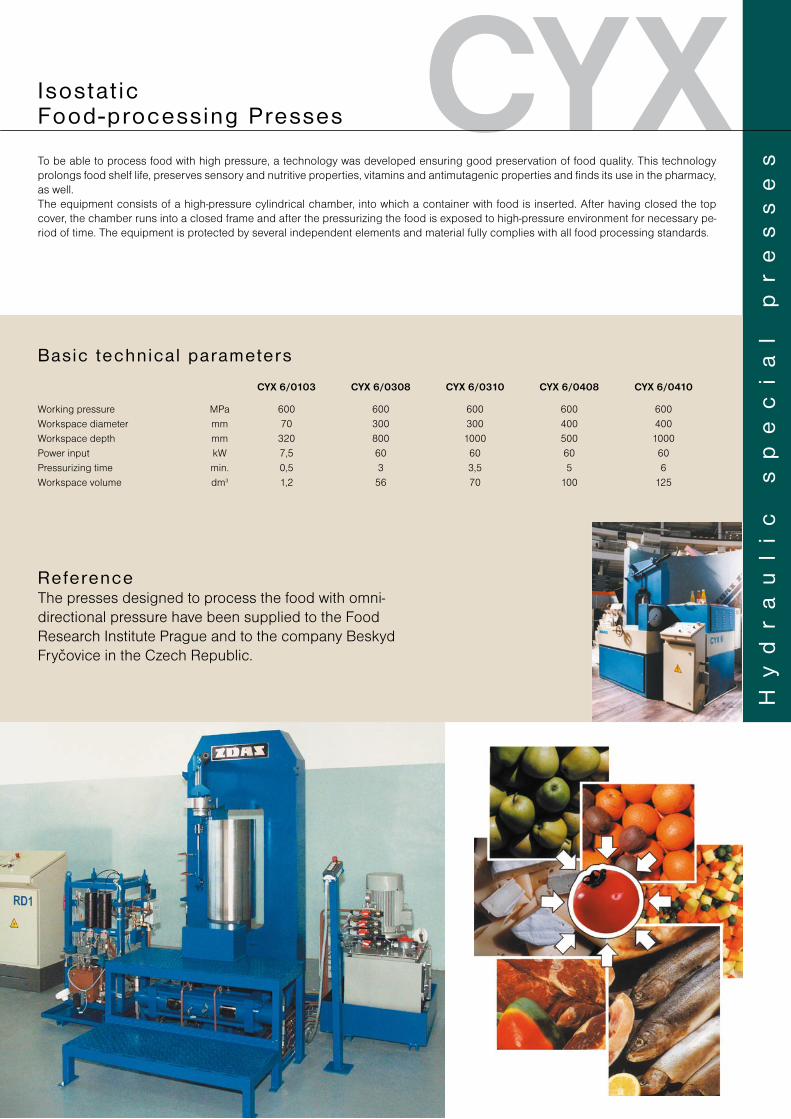
CYXTo be able to process food with high pressure, a technology was developed ensuring good preservation of food quality. This technology prolongs food shelf life, preserves sensory and nutritive properties, vitamins and antimutagenic properties and finds its use in the pharmacy, as well.The equipment consists of a high-pressure cylindrical chamber, into which a container with food is inserted. After having closed the top cover, the chamber runs into a closed frame and after the pressurizing the food is exposed to high-pressure environment for necessary pe-riod of time. The equipment is protected by several independent elements and material fully complies with all food processing standards.
Hy
dr
au
li
c
sp
ec
ia
l
pr
es
se
s
I sos tat ic Food-processing Presses
CYX 6/0103 CYX 6/0308 CYX 6/0310 CYX 6/0408 CYX 6/0410
Working pressure MPa 600 600 600 600 600Workspace diameter mm 70 300 300 400 400Workspace depth mm 320 800 1000 500 1000Power input kW 7,5 60 60 60 60Pressurizing time min. 0,5 3 3,5 5 6Workspace volume dm3 1,2 56 70 100 125
Basic technica l parameters
ReferenceThe presses designed to process the food with omni-directional pressure have been supplied to the Food Research Institute Prague and to the company Beskyd Fryčovice in the Czech Republic.
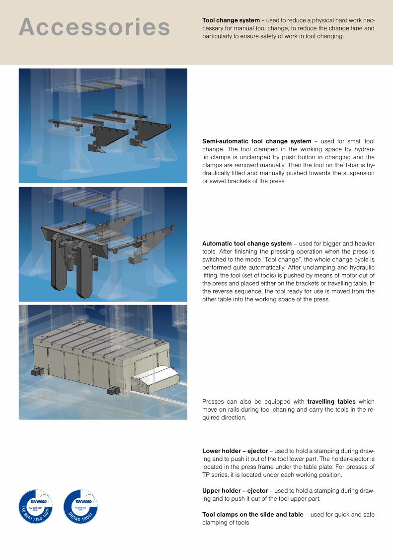
Semi-automatic tool change system – used for small tool change. The tool clamped in the working space by hydrau-lic clamps is unclamped by push button in changing and the clamps are removed manually. Then the tool on the T-bar is hy-draulically lifted and manually pushed towards the suspension or swivel brackets of the press.
Automatic tool change system – used for bigger and heavier tools. After finishing the pressing operation when the press is switched to the mode “Tool change”, the whole change cycle is performed quite automatically. After unclamping and hydraulic lifting, the tool (set of tools) is pushed by means of motor out of the press and placed either on the brackets or travelling table. In the reverse sequence, the tool ready for use is moved from the other table into the working space of the press.
Presses can also be equipped with travelling tables which move on rails during tool chaning and carry the tools in the re-quired direction.
Lower holder – ejector – used to hold a stamping during draw-ing and to push it out of the tool lower part. The holder-ejector is located in the press frame under the table plate. For presses of TP series, it is located under each working position.
Upper holder – ejector – used to hold a stamping during draw-ing and to push it out of the tool upper part.
Tool clamps on the slide and table – used for quick and safe clamping of tools
Accessories Tool change system – used to reduce a physical hard work nec-cessary for manual tool change, to reduce the change time and particularly to ensure safety of work in tool changing.
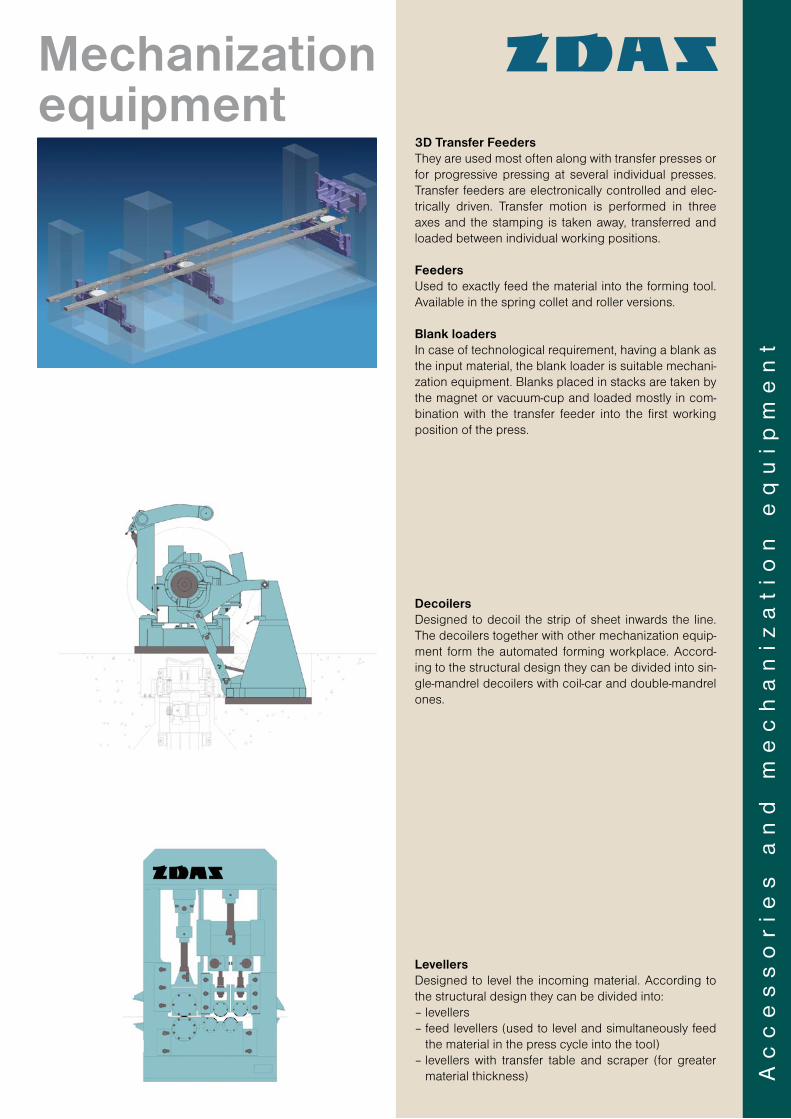
3D Transfer FeedersThey are used most often along with transfer presses or for progressive pressing at several individual presses. Transfer feeders are electronically controlled and elec-tri cally driven. Transfer motion is performed in three axes and the stamping is taken away, transferred and loaded between individual working positions.
FeedersUsed to exactly feed the material into the forming tool. Available in the spring collet and roller versions.
Blank loadersIn case of technological requirement, having a blank as the input material, the blank loader is suitable mechani-zation equipment. Blanks placed in stacks are taken by the magnet or vacuum-cup and loaded mostly in com-bination with the transfer feeder into the first working position of the press.
DecoilersDesigned to decoil the strip of sheet inwards the line. The decoilers together with other mechanization equip-ment form the automated forming workplace. Accord-ing to the structural design they can be divided into sin-gle-mandrel decoilers with coil-car and double-mandrel ones.
LevellersDesigned to level the incoming material. According to the structural design they can be divided into:– levellers– feed levellers (used to level and simultaneously feed
the material in the press cycle into the tool)– levellers with transfer table and scraper (for greater
material thickness) Ac
ce
ss
or
ies
a
nd
m
ec
ha
niz
at
ion
e
qu
ipm
en
t
Mechanization equipment
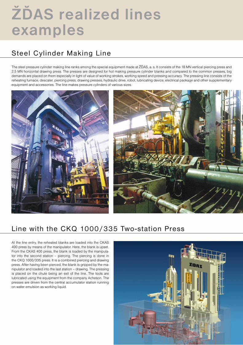
The steel pressure cylinder making line ranks among the special equipment made at ŽĎAS, a. s. It consists of the 18 MN vertical piercing press and 2,5 MN horizontal drawing press. The presses are designed for hot making pressure cylinder blanks and compared to the common presses, big demands are placed on them especially in light of value of working strokes, working speed and pressing accuracy. The pressing line consists of the reheating furnace, descaler, piercing press, drawing presses, hydraulic drive, robot, lubricating device, electrical package and other supplementary equipment and accessories. The line makes pressure cylinders of various sizes.
Steel Cy l inder Making L ine
Line with the CKQ 1000/335 Two-stat ion Press
At the line entry, the reheated blanks are loaded into the CKAS 400 press by means of the manipulator. Here, the blank is upset. From the CKAS 400 press, the blank is loaded by the manipula-tor into the second station – piercing. The piercing is done in the CKQ 1000/335 press. It is a combined piercing and drawing press. After having been pierced, the blank is gripped by the ma-nipulator and loaded into the last station – drawing. The pressing is placed on the chute being an exit of the line. The tools are lubricated using the equipment from the company Acheson. The presses are driven from the central accumulator station running on water emulsion as working liquid.
ŽĎAS realized lines examples
Li
ne
s
fo
r
ma
ss
p
ro
du
ct
io
n
of
p
re
ss
in
gs
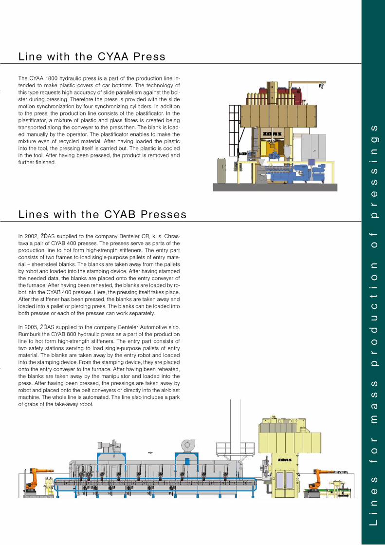
L ine wi th the CYAA Press
The CYAA 1800 hydraulic press is a part of the production line in-tended to make plastic covers of car bottoms. The technology of this type requests high accuracy of slide parallelism against the bol-ster during pressing. Therefore the press is provided with the slide motion synchronization by four synchronizing cylinders. In addition to the press, the production line consists of the plastificator. In the plastificator, a mixture of plastic and glass fibres is created being transported along the conveyer to the press then. The blank is load-ed manually by the operator. The plastificator enables to make the mixture even of recycled material. After having loaded the plastic into the tool, the pressing itself is carried out. The plastic is cooled in the tool. After having been pressed, the product is removed and further finished.
Lines wi th the CYAB Presses
In 2002, ŽĎAS supplied to the company Benteler CR, k. s. Chras-tava a pair of CYAB 400 presses. The presses serve as parts of the production line to hot form high-strength stiffeners. The entry part consists of two frames to load single-purpose pallets of entry mate-rial – sheet-steel blanks. The blanks are taken away from the pallets by robot and loaded into the stamping device. After having stamped the needed data, the blanks are placed onto the entry conveyer of the furnace. After having been reheated, the blanks are loaded by ro-bot into the CYAB 400 presses. Here, the pressing itself takes place. After the stiffener has been pressed, the blanks are taken away and loaded into a pallet or piercing press. The blanks can be loaded into both presses or each of the presses can work separately.
In 2005, ŽĎAS supplied to the company Benteler Automotive s.r.o. Rumburk the CYAB 800 hydraulic press as a part of the production line to hot form high-strength stiffeners. The entry part consists of two safety stations serving to load single-purpose pallets of entry material. The blanks are taken away by the entry robot and loaded into the stamping device. From the stamping device, they are placed onto the entry conveyer to the furnace. After having been reheated, the blanks are taken away by the manipulator and loaded into the press. After having been pressed, the pressings are taken away by robot and placed onto the belt conveyers or directly into the air-blast machine. The whole line is automated. The line also includes a park of grabs of the take-away robot.
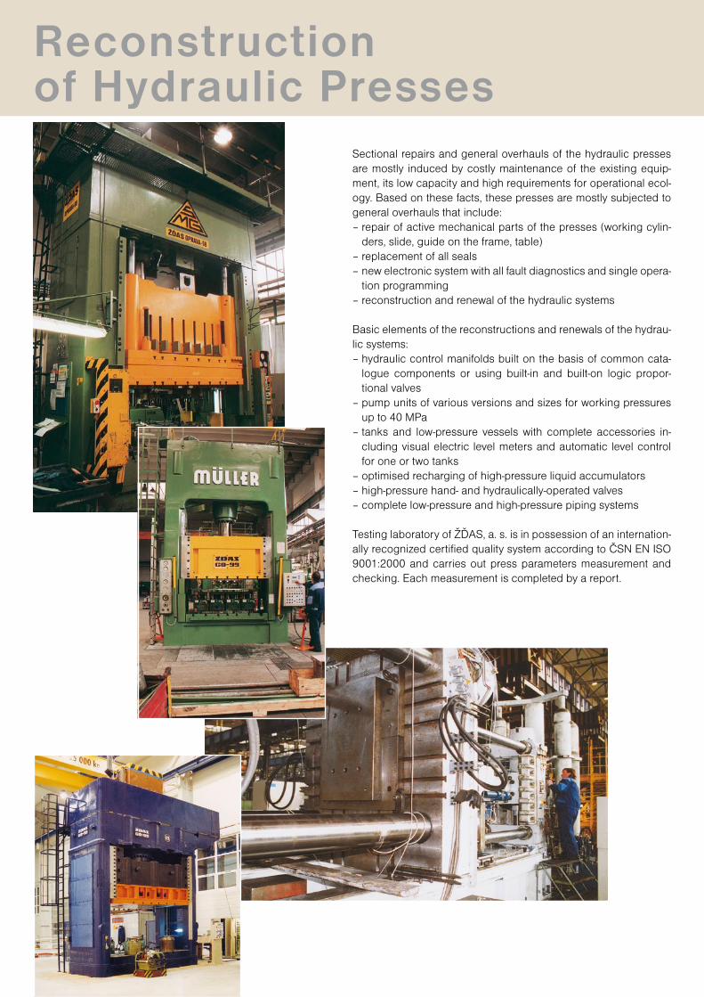
Reconstructionof Hydraulic Presses
Sectional repairs and general overhauls of the hydraulic presses are mostly induced by costly maintenance of the existing equip-ment, its low capacity and high requirements for operational ecol-ogy. Based on these facts, these presses are mostly subjected to general overhauls that include:– repair of active mechanical parts of the presses (working cylin-
ders, slide, guide on the frame, table)– replacement of all seals– new electronic system with all fault diagnostics and single opera-
tion programming– reconstruction and renewal of the hydraulic systems
Basic elements of the reconstructions and renewals of the hydrau-lic systems:– hydraulic control manifolds built on the basis of common cata-
logue components or using built-in and built-on logic propor-tional valves
– pump units of various versions and sizes for working pressures up to 40 MPa
– tanks and low-pressure vessels with complete accessories in-cluding visual electric level meters and automatic level control for one or two tanks
– optimised recharging of high-pressure liquid accumulators– high-pressure hand- and hydraulically-operated valves– complete low-pressure and high-pressure piping systems
Testing laboratory of ŽĎAS, a. s. is in possession of an internation-ally recognized certified quality system according to ČSN EN ISO 9001:2000 and carries out press parameters measurement and checking. Each measurement is completed by a report.
KM1
A
R 25
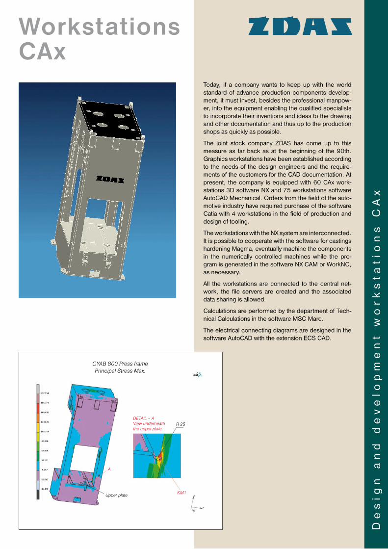
Today, if a company wants to keep up with the world standard of advance production components develop-ment, it must invest, besides the professional manpow-er, into the equipment enabling the qualified specialists to incorporate their inventions and ideas to the drawing and other documentation and thus up to the production shops as quickly as possible.
The joint stock company ŽĎAS has come up to this measure as far back as at the beginning of the 90th. Graphics workstations have been established according to the needs of the design engineers and the require-ments of the customers for the CAD documentation. At present, the company is equipped with 60 CAx work-stations 3D software NX and 75 work stations software AutoCAD Mechanical. Orders from the field of the auto-motive industry have required purchase of the software Catia with 4 workstations in the field of production and design of tooling.
The workstations with the NX system are interconnec ted. It is possible to cooperate with the software for castings hardening Magma, eventually machine the components in the numerically controlled machines while the pro-gram is generated in the software NX CAM or WorkNC, as necessary.
All the workstations are connected to the central net-work, the file servers are created and the associated data sharing is allowed.
Calculations are performed by the department of Tech-nical Calculations in the software MSC Marc.
The electrical connecting diagrams are designed in the software AutoCAD with the extension ECS CAD.
De
sig
n a
nd
de
ve
lop
me
nt
wo
rk
sta
tio
ns
CA
x
Workstations CAx
CYAB 800 Press framePrincipal Stress Max.
DETAIL – AView underneath the upper plate
Upper plate
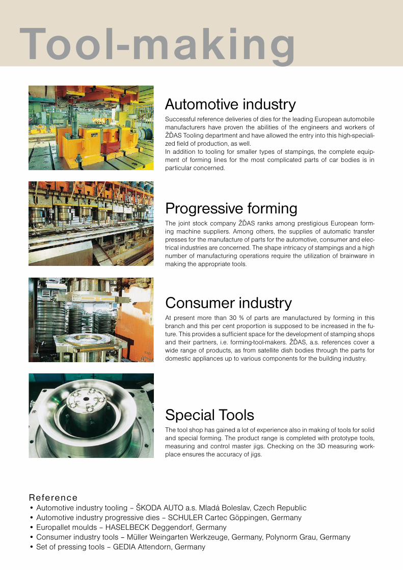
Reference• Automotive industry tooling – ŠKODA AUTO a.s. Mladá Boleslav, Czech Republic• Automotive industry progressive dies – SCHULER Cartec Göppingen, Germany• Europallet moulds – HASELBECK Deggendorf, Germany• Consumer industry tools – Müller Weingarten Werkzeuge, Germany, Polynorm Grau, Germany• Set of pressing tools – GEDIA Attendorn, Germany
Automotive industrySuccessful reference deliveries of dies for the leading European automobile manufacturers have proven the abilities of the engineers and workers of ŽĎAS Tooling department and have allowed the entry into this high-speciali-zed field of production, as well.In addition to tooling for smaller types of stampings, the complete equip-ment of forming lines for the most complicated parts of car bodies is in particular concerned.
Progressive formingThe joint stock company ŽĎAS ranks among prestigious European form-ing machine suppliers. Among others, the supplies of automatic transfer presses for the manufacture of parts for the automotive, consumer and elec-trical industries are concerned. The shape intricacy of stampings and a high number of manufacturing operations require the utilization of brainware in making the appropriate tools.
Consumer industryAt present more than 30 % of parts are manufactured by forming in this branch and this per cent proportion is supposed to be increased in the fu-ture. This provides a sufficient space for the development of stamping shops and their partners, i.e. forming-tool-makers. ŽĎAS, a.s. references cover a wide range of products, as from satellite dish bodies through the parts for domestic appliances up to various components for the building industry.
Special ToolsThe tool shop has gained a lot of experience also in making of tools for solid and special forming. The product range is completed with prototype tools, measuring and control master jigs. Checking on the 3D measuring work-place ensures the accuracy of jigs.
Tool-making
En
gin
ee
rin
g p
rod
uct
ion
PRAHA
BRNOJihlava
Kolín
D1
D1
ŽĎÁR n. Sáz.
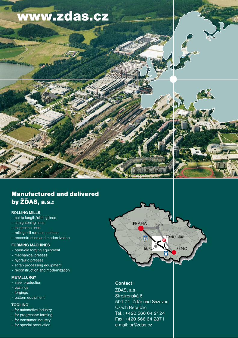
Contact:
ŽĎAS, a.s.Strojírenská 6591 71 Žďár nad SázavouCzech RepublicTel.: +420 566 64 2124Fax: +420 566 64 2871e-mail: [email protected]
www.zdas.cz
Manufactured and delivered by ŽĎAS, a.s.:
ROLLING MILLS– cut-to-length/slitting lines– straightening lines– inspection lines– rolling mill run-out sections– reconstruction and modernization
FORMING MACHINES– open-die forging equipment– mechanical presses– hydraulic presses– scrap processing equipment– reconstruction and modernization
METALLURGY– steel production– castings– forgings– pattern equipment
TOOLING– for automotive industry– for progressive forming– for consumer industry– for special production