Embed Size (px)
Citation preview

The Twelfth Scandinavian International Conference on Fluid Power, May 18-20, 2011, Tampere, Finland
HYDRAULIC RUNNING ROBOTS:
THE PROSPECTS FOR FLUID POWER IN AGILE LOCOMOTION
Bhatti J., Plummer A. R.
The Centre for Power Transmission and Motion Control
University of Bath
Bath BA2 5DR
UK
ABSTRACT
The majority of the Earth’s land mass is inaccessible to wheeled vehicles. Legged
locomotion is a potential solution to this problem, allowing mobile machines to traverse
rough terrain and step over obstacles. Many hundreds of walking machines are in
existence, albeit mostly in research laboratories rather than in productive employment.
Walking machines are generally slow, and unable to respond sufficiently quickly to
external disturbances and foot slippage. Thus machines with a dynamic capability, i.e.
with sensing, actuation and control systems which enable operation outside the
constraints of static balance, are likely to be much more useful. This paper briefly
reviews the history of legged locomotion, focusing on the development of dynamic
(running) robots and their associated control algorithms. To deliver sufficient power to
many independently controlled actuators, whilst minimising weight and size, hydraulic
actuation has normally been chosen for running robots. Comments are included in the
paper about power consumption, and the challenge for fluid power researchers to
propose more efficient solutions which are still suitable given the constraints
(particularly weight) associated with this application.
KEYWORDS: Legged robots, hydraulic robots, hopping dynamics, energy efficiency

1. OVERVIEW
Animate legged locomotion has demonstrated itself to be a very effective method of
traversing rough, slippery, sloping and shifting terrain. Legs may provide some benefits
for mobile machines used in agriculture, defence, entertainment and the exploration of
earth and space.
Legs usually have several of degrees of freedom and are complex to control. Their main
advantage, the ability to adapt to rough terrain, could not begin to be properly exploited
until the first computer controlled walking machine was made in 1966 [1]. Development
of walking machines since then has progressed at a steady rate.
Running robots go out of balance during part of their normal movement cycle, and react
to forces and inertia, not just position. When static balance is not a constraint, robots are
able to move at much greater speeds and perform advanced manoeuvres such as
running, jumping and turning rapidly.
Marc Raibert made considerable progress in understanding running dynamics in the
1980’s at Carnegie-Mellon University and MIT [2]. He was able to build and control a
number of tethered running machines. High power, lightweight actuation was a
fundamental requirement, and this was achieved using fluid power.
BigDog, Figure 1, is a semi-autonomous hydraulically actuated quadruped and is
currently the most capable dynamic walking and running machine [3]. It has been
developed by Boston Dynamics, a company founded by Marc Raibert in 1992, and can
be considered a direct descendent of his earlier robots. BigDog development started in
2003 under a US DARPA (Defense Advanced Research Projects Agency) contract, and
the robot is intended to be able to follow soldiers on all terrains carrying equipment.
Although detailed information on this robot is not public, videos have been released
demonstrating that BigDog can trot over difficult surfaces while carrying a payload, and
can recover from severe external disturbances.
The key challenge for BigDog and similar future machines is range. An acceptable
balance between payload capability, size and weight of fuel (energy) storage, and
refuelling intervals has not been achieved. Although hydraulic actuation provides
excellent power density and performance, it does not (yet) provide adequate efficiency
for this application.
Figure 1: BigDog, a quadruped with hydraulic actuation [3]
2. LEGGED LOCOMOTION: BACKGROUND
2.1. Walking machines relying on static balance
A major issue in legged locomotion is controlling the robot so that it remains upright.
One approach to this is to always maintain static balance. This means that, if the robot
were to freeze at any point during its motion, it would not fall over. Static balance is
achieved by keeping the centre of gravity (CoG) above a particular base plane which is
determined by the placement of the feet [4]. Maintaining balance is then purely a
kinematic problem. For example, this is how the SILO-6 robot shown in Figure 2 walks
[5]. SILO-6 has a large base, the polygon formed by its feet, and moves at low speeds
so maintaining static balance is sufficient. Less statically stable robots, with smaller
bases such as bipeds like Honda’s Asimo in Figure 3, have to move very slowly in order
to stay balanced. Higher speeds can be achieved by moving between different statically
balanced positions and using a control strategy which is robust to momentary
imbalance. The design philosophy for robots of this kind is to start with static stability
and extend the capabilities of the mechanical and controller design to perform dynamic
tasks. Dynamic tasks, as well as requiring a more complex controller also require
actuators which can respond quickly and generate much higher forces.
Figure 2: Example of a purely position controlled robot [5].
Figure 3: Asimo, a humanoid biped developed by Honda [6].
2.2. Running dynamics
The importance of hopping
Running does not rely on a substantial base plane area: intermittent point contact is
sufficient. A single legged robot provides a useful starting point for research on multi-
legged running robots. Locomotion by hopping on one leg was first solved by Raibert
in the 1980s [2]. It was also shown that the basic control strategies for hopping could
also be applied to bipeds and quadrupeds.

Figure 4 shows the 4 main events during steady dynamic hopping. From left to right
they are: lift-off, flight, touchdown, stance and back to lift-off. During the flight phase
the robot’s CoG follows a ballistic trajectory. The distance between the foot at lift-off
and subsequent touch-down is the “stride”. Biped running is essentially the same as
hopping; alternating legs provides more time for leg repositioning when the flight phase
is short.
A quadruped has redundant legs which may be used to increase stability. Quadrupeds
can run with a number of different gaits, but legs are usually paired so that a gait
approximates to bipedal running. Some are shown in Figure 5. Trotting minimises body
rotation because diagonally opposite legs are synchronised. Pacing, in which legs on the
same side are synchronised, leads to more body roll. Bounding, in which front and rear
leg pairs are synchronised, differs from conventional bipedal running as there is usually
a longitudinal offset between the CoG and each ground contact point. If the front and
rear leg pairs in a bound are not perfectly synchronised, the motion may become a
rotary or transverse gallop.
Figure 4: Stages of hop
Figure 5: Quadruped gaits [2]
Flight
Touch-
down
Stance
Lift-off Lift-off

Raibert decomposed hopping control into three separate parts that regulate the body’s
forward running speed, hopping height, and attitude [2,7,8]:
• Forward running speed – The control system positions the foot during the flight
phase to influence the accelerations of the body that would occur during the next
stance phase.
• Hopping height – the control system uses leg thrust during the stance phase to
excite and modulate resonant oscillation of the sprung leg and body.
• Body Attitude – The control system keeps the body level by exerting torques
about the hip axes during the stance phase.
The first two of these are analysed in the next sections.
Hopping forward speed control
The SLIP (spring-loaded inverted pendulum) model, Figure 5, is the simplest model of a
body hopping on a sprung leg. It consists of a point mass (m) representing the body, and
a massless elastic spring (stiffness k, free length L) with variable orientation (θ) representing the leg. For this model, for a given initial height and horizontal velocity,
the lift-off angle after the stance phase will be a function of the touch-down angle.
Additionally, there exists an angle for which the motion becomes symmetric i.e. the lift-
off angle equals the touch-down angle. For this angle, the mass will hop passively at a
constant height and constant average velocity.
Figure 5: SLIP model
When not in contact with the ground, the mass follows a parabolic trajectory. If the
position of the point mass is given by the vector then the equation of motion
is given by:
=
g
L
m
k 0-1- r
rp�� when L<r , and
=
g
0-p�� when L=r (1)
where the leg vector depends on the foot contact location:
(2)
The motion of the particle subsequent to touch-down, and therefore the lift-off angle,
depends on the touch-down angle. For a given hopping height and velocity there is a
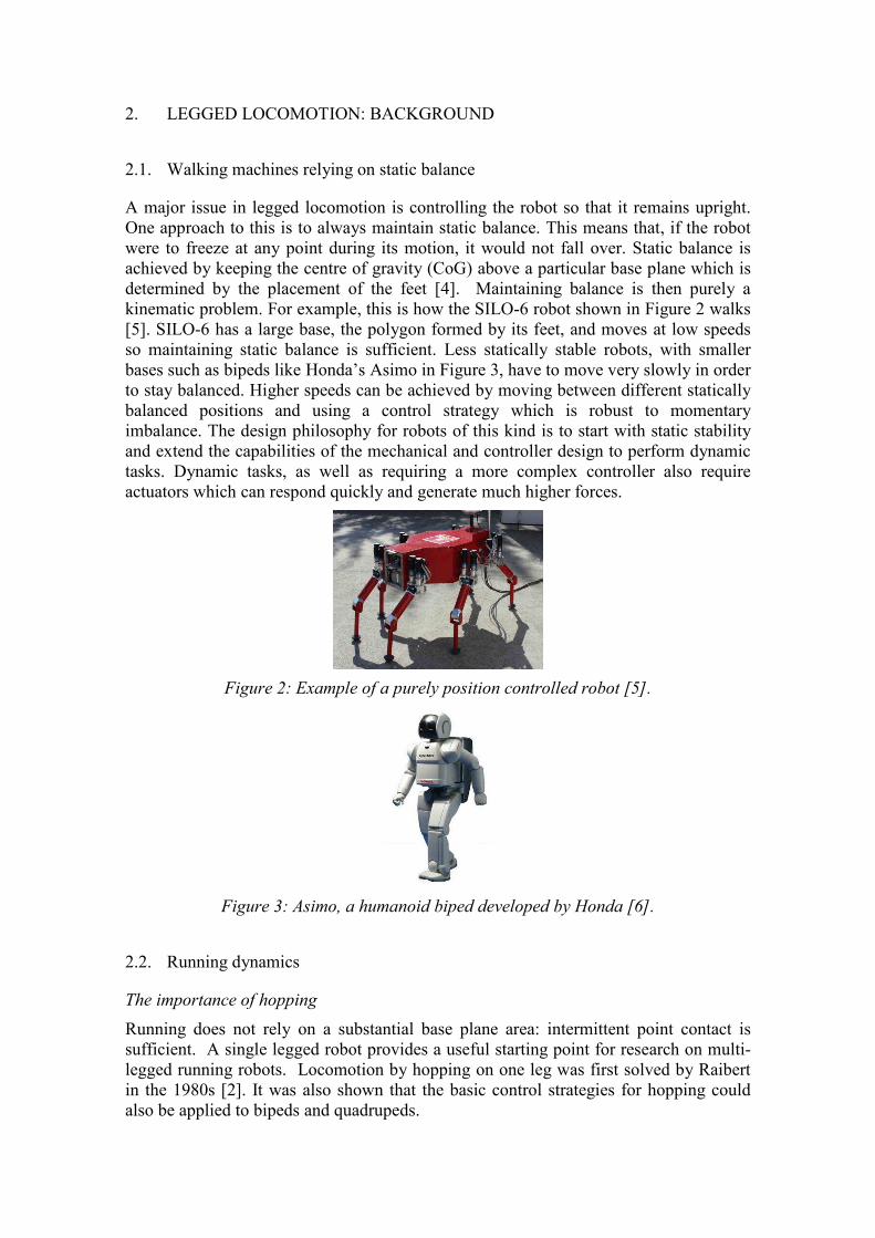
touch-down angle which results in a symmetric lift-off angle. This angle, in Figure
6a, results in steady passive dynamic hopping at a fixed height and average velocity.
Small deviations in the forward velocity will not self-correct however. The hopper will
lose/gain velocity and gain/lose height until it topples unless controlled.
The effect of the touch-down angle is shown in Figure 7. The plot is generated by
integrating Eqn. 1. with the parameters values and initial conditions listed in Table 1.
The value of in this case is . Figure 7 shows that increasing the touch-
down angle by 50% from the steady passive dynamic hopping angle causes the next hop
to reach a higher flight apex height and therefore reduced horizontal velocity. Similarly,
a decrease in by 50% reduces height and increases forward velocity. This fact means
horizontal velocity can be controlled by changing the touch-down angle about the
steady hopping angle .
Table 1: SLIP model parameters.
Horizontal velocity (at bottom)
Free leg length
Maximum leg compression
Bounce frequency ( mk / )
Touch down angle Varying
Figure 6: Stance phase touch-down/lift-off angles.
(a) (b)

Figure 7: SLIP model passive dynamic motion for different touch-down angles showing
effect of changing touch-down angle.
For a range of running speeds, the effects of a deviation on the running speed have
been plotted in Figure 8. It can be seen that is independent of running speed for small
. Thus a simple proportional controller which adjusts touch down angle in proportion
to forward speed error works as an effective closed loop speed control system.
Figure 8: Effect of changing touch-down angle on forward velocity at different
velocities: 0.00, 1.12, 3.36, 5.57 and 8.85 m s-1.
Hopping height control
In reality there will be losses associated with the leg, and a simple extension to the SLIP
model is to include a damper in parallel with the spring (Figure 9). During flight (a) the
mass experiences acceleration due to gravity only. Contact with the ground or
touchdown (b) occurs when . Motion during the stance phase (c) is
affected by the motion of the actuator which adds energy to the system. If sufficient

energy is available then lift-off (d) into flight occurs when . The equation of
motion is:
mgrykrycym −=−+−+ )()( ���� when 0<− ry , and gy -=�� when 0≥ry − (3)
The maximum height reached during flight, in other words the maximum gravitational
potential energy, can be controlled. The motion of the actuator during the stance phase
determines how much energy is added to the system. Consider the case of the actuator
expanding at a constant velocity throughout the stance phase, as shown in Figure
10. Using a simplifying assumption that accelerations during the stance phase are
much higher than g, it can be shown that to achieve steady hopping with apex height hd:
(4)
where and CR is the coefficient of restitution:
(5)
Thus a controller must adjust the actuator velocity to achieve the desired hopping
height; and a simple proportional-integral closed loop position controller may be
sufficient. An example response (using a more complex model than Eqn. 3) is shown in
Figure 11.
Figure 9: Model with damping
Figure 10: Required actuator motion during stance (Ts) and flight (Tf) phases.
(a) Flight (b) Touch-down (c) Stance (d) Lift-off

Figure 11: Example closed loop hopping height control: line is demand, points are
height apex results.
3. HYDRAULIC RUNNING ROBOTS
3.1. The first hydraulic legged machines
Experiments with walking machines driven by mechanical linkages have been on-going
for centuries. GE’s “walking truck, developed in the mid-1960’s, was the first serious
hydraulic system, and marked a significant leap in sophistication [9]. Each of the four
legs was controlled by one of the driver’s limbs, and force-feedback was incorporated to
make the tele-operation task easier. Nevertheless driver workload was high, and about
15 minutes was the limit of endurance. The project was funded by the US military.
Figure 12: The GE Walking Truck
Computer control was clearly going to be essential to operate these complex devices.
The first man-carrying computer-controlled walking machine was developed by
Sutherland from about 1980 [10] (Figure 13). This used the ‘virtual leg’ concept,
whereby sub-groups of the 6-legs could be linked hydraulically to act in unison,

following the controller’s virtual leg commands. Raibert also worked on this machine,
adopting the virtual leg concept to control his multi-legged running robots.
Many other hydraulic walking machines have been built. John Deere’s walking tractor,
developed in Finland, is a good example [11]. However the design requirements for
running are significantly different from walking.
Figure 13: Sutherland’s walking machine [10]
3.2. Raibert’s hopping and running robots [2,3,7]
Raibert’s first hopping monopod was pneumatic, but he subsequently developed
hydraulic monopods, bipeds and quadrupeds, albeit with air-springs providing leg
compliance (Figure 12). The robots could be programmed to jump over or climb simple
obstacles, somersault, and a running speed of 6m/s was achieved. The quadruped, also
shown in Figure 13, could run with trotting, pacing or bounding gaits. Each leg was
actuated by three hydraulic cylinders, supplied by pressure controlled servovalves.
Thus each valve drive signal could be considered as a force command. Hydraulic and
electrical power supplies were external, as was the control computer (a DEC VAX).
(a) (b) (c)
Figure 12: Raibert’s Carnegie-Melon / MIT robots (1980’s)
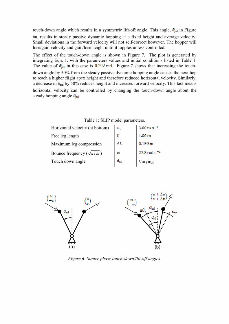
BigDog, Figure 14, appears to use the same control principles as the earlier robots,
although detailed information has not been published. Typically it is programmed to
adopt a trotting gait, but to improve stability at the expense of speed, the flight phase is
very short or eliminated. The key advances are that it is entirely self contained, and can
adapt to rough, slippery and sloping ground. It can trot at 1.6m/s, or 2m/s with a flight
phase
The hydraulic pump is driven by a two-stroke single cylinder 11kW engine. There are
four actuators per leg, and onto each is mounted a lightweight servovalve (Moog 30
series). Position and force is measured at each actuator.
Boston Dynamics is also currently developing PETMAN (Protection Ensemble Test
Mannequin), a biped for use in testing soldiers’ equipment (Figure 15).
Table 2: BigDog parameters [3]
Typical speed 1.6 m/s
Maximum speed achieved 3.1 m/s
Mass 109 kg
Maximum payload 150 kg
Height 1.0 m
Width 1.1 m
Length 0.3 m
(a) Side (b) Front (c) Leg
Figure 13. Carnegie-Melon / MIT Quadruped

Figure 14: Boston Dynamics’ BigDog
Figure 15: Boston Dynamics’ PETMAN [12]
3.3. Other hydraulic running robots
KenKenII is a robot with a leg structure proportioned like that of a dog [13,14]. As seen
in Figure 16, KenKenII features a spring connecting the heel to the thigh. The legs can
only move in the sagittal plane. Experimental results seem limited to a few hops.
HyQ is a hydraulic quadruped under development at the Italian Institute of Technology
(Figure 17) [15,16]. Inspired by BigDog, hardware design and construction are nearly
complete and control investigations are progressing.
Leg actuator

Figure 16: KenKenII, an articulated running robot.
Figure 17: HyQ, ‘Hydraulic Quadruped’, from IIT
4. THE HYDRAULIC EFFICIENCY CHALLENGE
BigDog is an untethered, agile, all-terrain robot and is the first of its kind. Its agility,
both in terms of its ability to respond to disturbances and its ability to run, is only made
possible by the use of hydraulic actuation. The actuation system has many degrees of
freedom, has high power but is light and compact. Nevertheless, challenges for future
development are:
• a higher payload capacity (180 kg), requiring higher maximum power output;
• a longer range (32 km) , requiring a lower average power input [17].
Thus improving the efficiency of conversion of fuel to actuator output power is key.
Any changes which substantially increase the weight of the hydraulic system will also
be unacceptable.

The minimum consumption of hydraulic power by a valve-controlled actuator running
from a constant supply pressure is given by the product of peak actuator force and mean
actuator velocity. This is also equivalent to the product of peak force and mean velocity
(relative to the body) at the robot’s foot. During running, the peak force is vertical but
the highest mean foot velocity is longitudinal; nevertheless a high horizontal foot force
capability is also required to cope with rough terrain and disturbances, and in the
following the peak horizontal force requirement will be assumed to be the same as the
vertical requirement.
Let the stance phase be a proportion of the total cycle period as follows:
fs
s
s TT
Tr
+= (6)
Thus if u is the mean forward velocity of the robot, assuming that longitudinal foot
motion dominates, then mean absolute foot velocity relative to the body for a monopod
is:
uru sf 2= (7)
For a biped this expression gives the sum of the mean foot velocities. The mean vertical
foot force equals the robot weight, so the foot force during stance must increase if the
stance time decreases. If the vertical foot force during stance is approximated as half a
sine wave, then the peak force is given by:
sf r
mgπF
2= (8)
where m is the total robot mass. For example, in Figure 18, Ts = 0.14, Tf = 0.22 and m =
30 kg, giving a peak foot force of 1190 N, consistent with the peak force shown in the
Figure.
The total fluid power requirement is the product of uf and Ff:
mguπW = (9)
This expression applies irrespective of the number of legs: a trotting quadruped for
example shares each stance load between two legs (halving Ff) but the flow requirement
is doubled. For example, for BigDog of mass 150kg including a payload, trotting at u =
2m/s, Eqn. 9 gives a power requirement of 9.25 kW. The theoretical minimum power
requirement depends on the co-efficient of restitution (Eqn. 5) apex height and stride
rate; for example if these combined to give a passive height loss of 0.1m/s, then the
minimum power requirement for a 150kg machine is 150 W. Thus the hydraulic
actuation system appears very inefficient.
Other practical characteristics will make the situation even worse. At 210 bar supply
pressure a Moog Type 30 servovalve will have an internal leakage consisting of [18]:
• tare flow (pilot flow and bushing laminar leakage), specified as less than 0.35
L/min,
• spool null leakage flow, specified as less than 0.25 L/min for a “special low
leakage” version.
So a typical total internal leakage when the valve is closed would be ≈0.5 L/min. Thus, with 16 valves in total, BigDog’s quiescent power drain due to valves alone is about 2.8
kW.

19 19.1 19.2 19.3 19.4 19.5 19.6 19.7 19.8 19.9 20-0.1
0
0.1
Bo
dy
po
sit
ion
(m
)
19 19.1 19.2 19.3 19.4 19.5 19.6 19.7 19.8 19.9 20
-10
-5
0
x 10-3
Ac
tua
tor
po
sit
ion
(m
)
19 19.1 19.2 19.3 19.4 19.5 19.6 19.7 19.8 19.9 20
-1000
-500
0
Time (s)
Sp
rin
g f
orc
e (
N)
Figure 18: Simulated vertical displacements and force during hopping (30kg machine)
5. CONCLUSIONS
This paper has reviewed progress in dynamic legged locomotion over the past five
decades. The world-leading work of Marc Raibert and colleagues into the equivalence
between multi-legged robots and monopedal hopping is described, as well as the
partitioning of the control task into three separate control problems. Some analysis is
presented allowing the open-loop forward speed control and hopping height
characteristics to be quantified. Raibert’s published controllers use manually tuned
proportional or proportional-derivative control, driving pressure-control servovalves,
and are not based on a plant model.
Hydraulic actuation is currently the only feasible solution for running robots with many
independently actuated joints. Nevertheless instantaneous force requirements are high
(typically several times the static weight), but as these ground impact forces are
momentary, the force capability is not utilised for much of the leg’s movement cycle,
leading to a lack of energy-efficiency. Improving efficiency could extend the range of a
running robot to become a practical machine.
Some other topics that require further research include:
• Stability and manoeuvrability. Little research on traversing rough, sloping and
uncertain terrain at speed has been published, nor has a comparison of the merits
of different gaits, transitions between these and especially asymmetric gaits
which are common among animals. There may not always be a continuous path
of support so foot placement may also be studied. Controllers are often derived
using small angle assumptions which become less accurate during high speed
running, jumping and turning.

• Sensors and intelligence. Vision systems or range finders may be integrated in
the control loop to assist terrain mapping, maintaining balance, foot placement
or path planning.
• Robot dynamics. Designing a robot to display a passive hopping mode has
already been shown to be important for running. Further optimisation of the
passive dynamics (e.g. leg swing) could increase speed and efficiency while
reducing the load on actuators.
Whilst common in science fiction, the future widespread use of dynamic legged
machines in the real world remains open to debate. Nevertheless, the technical
feasibility of self contained running robots has been demonstrated, and further
optimisation, aided by hydraulics research engineers is only a matter of time. The first
applications are likely to be military, but use in agriculture and in hazardous off-road
environments or rescue situations may follow.
ACKNOWLEDGEMENTS
The authors thank Dr M N Sahinkaya and Dr P Iravani, both of the University of Bath,
for their contributions to this work, and the Italian Institute of Technology (IIT) for
supporting collaborative work in legged locomotion.
REFERENCES
[1] M. F. Silva and J. A. MACHADO, “A historical perspective of legged robots,”
Journal of Vibration and Control, vol. 13, no. 9, pp. 1447–1486, 2007.
[2] M. Raibert, Legged robots that balance. MIT press Cambridge, MA, 1986.
[3] M. Raibert, K. Blankespoor, G. Nelson, and R. Playter, “Bigdog, the rough-
terrain quaduped robot,” Proceedings of the 17th International Federation of
Automation Control.(April 2008).
[4] T. Bretl and S. Lall, “Testing static equilibrium for legged robots,” IEEE
Transactions onRobotics, vol. 24, no. 4, pp. 794–807, 2008.
[5] “DeptOfAutomaticControl-SILO6-IAI-CSIC.” [Online]. Available:
http://www.iai.csic.es/users/silo6/SILO6_WalkingRobot.htm#Pictures. [Accessed:
04-Nov-2010].
[6] “asimo-walk.jpg (JPEG Image, 312×383 pixels).” [Online]. Available:
http://www.diseno-art.com/images/asimo-walk.jpg. [Accessed: 10-Nov-2010].
[7] M. Raibert, "Trotting, pacing and bounding by a quadruped robot," Journal of
biomechanics, vol. 23, 1990, p. 79–81.
[8] M. Raibert, M. Chepponis, H. Brown, “Running on four legs as though they were
one,” IEEE Journal of Robotics and Automation, vol. RA-2, no. 2, 1986, p.70-82.
[9] R. Mosher, "Test and evaluation of a versatile walking truck," Proceedings of the
Off-Road Mobility Research Symposium, International Society for Terrain
Vehicle Systems, 1968, pp. 359-379.
[10] I. Sutherland and M. Ullner, "Footprints in the asphalt," International Journal of
Robotics Research, vol. 3, 1984, pp. 29-36.

[11] Billingsley, J., Visala, A. and Dunn, M.,“Robotics in Agriculture and Forestry”.
In: Siciliano, Bruno and Khatib, Oussama, (eds.) Springer handbook of robotics.
Springer-Verlag, Berlin, Germany, 2007, pp. 1065-1077. ISBN 978-3-540-23957-
4
[12] http://www.bostondynamics.com/robot_petman.html [Accessed: 10-Mar-2011].
[13] “Biologically-Inspired Running Robots.” [Online]. Available:
http://www.ritsumei.ac.jp/se/~gen/Kenken/kenken_en.htm#exp_2. [Accessed: 18-
Nov-2010].
[14] Susumu Ohtake, M. Yamakita, and S. Hyon, “Control of under actuated biped
running robot via synchronous oscillator,” in 2008 SICE Annual Conference, pp.
3367-3371, 2008.
[15] M. Focchi, E. Guglielmino, C. Semini, T. Boaventura, Y. Yang, and D. G.
Caldwell, “Control of a hydraulically-actuated quadruped robot leg,” in 2010
IEEE International Conference on Robotics and Automation, pp. 4182-4188,
2010.
[16] C. Semini, N. G. Tsagarakis, B. Vanderborght, Y. Yang, and D. G. Caldwell,
“HyQ - Hydraulically actuated quadruped robot: Hopping leg prototype,” in 2008
2nd IEEE RAS & EMBS International Conference on Biomedical Robotics and
Biomechatronics, pp. 593-599, 2008.
[17] Nathan, S. “Marc Raibert of Boston Dynamics” The Engineer, 22nd Feb 2010.
[18] Moog Inc, “ Type 30 Nozzle-Flapper Flow Control Servovalves”