Embed Size (px)
Citation preview

(20/02/2012) 70-02-M184EN
70
HYDRAULIC SCHEMATIC DIAGRAMS
page
MHT 10120. . . . . . . . . . . . . . . . . . . . . . . . . . . . . . . . . . . . . . . . . . . . . . . . . . . . . . . . . . . . . . . . . . . . . . . .3
– LEGEND . . . . . . . . . . . . . . . . . . . . . . . . . . . . . . . . . . . . . . . . . . . . . . . . . . . . . . . . . . . . . . . . . . . . . . . . . 3
– LAYOUT . . . . . . . . . . . . . . . . . . . . . . . . . . . . . . . . . . . . . . . . . . . . . . . . . . . . . . . . . . . . . . . . . . . . . . . . . 5
MHT 7140 - 990. . . . . . . . . . . . . . . . . . . . . . . . . . . . . . . . . . . . . . . . . . . . . . . . . . . . . . . . . . . . . . . . . . . .6
– LEGEND . . . . . . . . . . . . . . . . . . . . . . . . . . . . . . . . . . . . . . . . . . . . . . . . . . . . . . . . . . . . . . . . . . . . . . . . . 6
– LAYOUT . . . . . . . . . . . . . . . . . . . . . . . . . . . . . . . . . . . . . . . . . . . . . . . . . . . . . . . . . . . . . . . . . . . . . . . . . 7
MHT 10160 - 10180 . . . . . . . . . . . . . . . . . . . . . . . . . . . . . . . . . . . . . . . . . . . . . . . . . . . . . . . . . . . . . . . .8
– LEGEND . . . . . . . . . . . . . . . . . . . . . . . . . . . . . . . . . . . . . . . . . . . . . . . . . . . . . . . . . . . . . . . . . . . . . . . . . 8
– LAYOUT . . . . . . . . . . . . . . . . . . . . . . . . . . . . . . . . . . . . . . . . . . . . . . . . . . . . . . . . . . . . . . . . . . . . . . . . . 9
MHT 10210 - 10225 . . . . . . . . . . . . . . . . . . . . . . . . . . . . . . . . . . . . . . . . . . . . . . . . . . . . . . . . . . . . . . . .10
– LEGEND . . . . . . . . . . . . . . . . . . . . . . . . . . . . . . . . . . . . . . . . . . . . . . . . . . . . . . . . . . . . . . . . . . . . . . . . . 10
– LAYOUT . . . . . . . . . . . . . . . . . . . . . . . . . . . . . . . . . . . . . . . . . . . . . . . . . . . . . . . . . . . . . . . . . . . . . . . . . 11

(20/02/2012)70-02-M184EN
70
2 HYDRAULIC SCHEMATIC DIAGRAMS

(20/02/2012) 70-02-M184EN
70
3HYDRAULIC SCHEMATIC DIAGRAMS
Ref. DescriptionPosition on the
diagramFeatures (Optional)
A Pressure accumulator O18
C.1 Manifold 1 O35
C.2 Manifold 2 Q39
C.3 Manifold 3 Q41
CPD Block and balancing valve C17
CSD Double block and balancing valve C10
CSP Pilot-operated relief valve C7 / C13 / C16
D. Directional control valve I18
E Solenoid valve C31
E.C.L. Levelling check solenoid valve O13 / O14
E.F.S. Parking brake solenoid valve A30
FA Suction fi lter S4 / S5 / S32
FDAR Rear axle disk brake C24 / E24
FDAV Front axle disk brake C36 / E36
FR Exhaust fi lter S34
FS Parking brake control cylinder C35
I.D. Power steering E34
M Manipulator M18
MI Hydrostatic motor M34
MT I.C. engine M22
M.V. Fan motor Q17
P. Pump Q4 / Q6
P.A. Optional connector C11
PH Hydrostatic pump M23
R Hydraulic fl uid tank S4
Rd Oil radiator Q38
VC Compensation cylinder A19 DE 105x75 C 1095
V.C.A. Accumulators charge valve Q8
V.C.I. Slewing cut off valve O15
VCLR Slow-fast speed control cylinder C33
V.D. Steering cylinder C24 / E36
V.F. Brakes valve C41
VI Slewing cylinder A14 / A16 DE 135x95 C 510
V.I. Inching valve I30
VL Lift cylinder A8 DE 180x115 C 1540
V.L.* Levelling cylinder M11 DE 140x65 C 170
VM Maximum pressure valve O5
VSLR Slow-fast speed control valve A26
VT Boom extension cylinder A11 DE 105x80 C 3973
Y101 Forward movement solenoid valve K26 / K27
Y102 Reversing solenoid valve K24 / K25
Y103 1200rpm solenoid valve O5
Y110 High speed solenoid valve A27
Y111 Low speed solenoid valve A27
Y114 RH levelling solenoid valve O11
Y115 LH levelling solenoid valve O13 / O14
Y116 Crab steering solenoid valve C31
Y117 Four-wheel steering sol.valve C33
Y125 Optional 2 proportional solenoid valve G10 / G11
LEGEND
MHT 10120

(20/02/2012)70-02-M184EN
70
4 HYDRAULIC SCHEMATIC DIAGRAMS
Ref. DescriptionPosition on the
layoutFeatures (Optional)
Y126 Optional 1 proportional solenoid valve E10 / E11
Y127 Retraction proportional solenoid valve E12 / E13
Y142 Extension proportional solenoid valve G12 / G13
Y146 Parking brake solenoid valve A29 / A30
Y611 VRD proportional solenoid valve I6
Y633 VS solenoid valve G17
Y955 VCI solenoid valve M15

70
(20/02/2012) 70-02-M184EN
5HYDRAULIC SCHEMATIC DIAGRAMS
LAYOUT
32 bar 440 bar512 bar
512 bar
C.3C.2
C.1
MI
PH
V.I.
3bar
Rd
FA2bar
FR
ab
X2X1 B
AT
R T1 T
G S MAX1 X2
A
B
MBPS
3 bar
MT
Ø1.5
Lpst
()
n 0.8
()
n
Ø2.0Ø0.8 Ø2.0Ø0.8
) (
Ø2.0Ø0.8
a3a2
b2 b3
P.A.
205 bar
Ø1.2 Ø1.2
V.L.*
E.C.L.
23 BAR0,7 LITRE
A
C2
V2
C1
V1
VI VC
VL
C2 C1
V2 V1CPD
PL
VT
R
C2C1
V1 V2CSDV1
C1
V2
C2
CSP
300 bar
175 bar
L B
A
M.V.
FA
VM
B
S
X
A3 B3A2 B2A1 B1LS SSX A4 B4
a4a1 b4
200 bar
T P
M
CSP C2
V2
C1
V1
VI
B
V.C.A.
P.
V.C.I.
b1
D.
CSP
21
PT
B A
0,7 Lt35 bar
35 bar0,7 Lt
E.F.S.
V.F.
R2
R1
T2
T1
R NBA
TP
R
L
P
T
V.D.
V.D.I.D.
E
VSLR
FSVCLR
FDAV
FDAV
FDAR
FDAR LS
200 bar
220 bar
220 bar
30bar
15L/min
350
bar
0.4
L/m
280 bar
300 bar 35
0 b
ar
20
0 b
ar
280 bar
FA10 MICRONS
300 bar 300 bar
300 bar 300 bar
300 bar 300 bar
Ø2.0Ø0.8
a1
Y633
VS
Y127
Y142
Y126
Y125
Y611
VRD
Y103 Y115Y114
Y955
Y11
1Y
110 Y146
Y11
7
Y11
6
Y102 Y101
S
Q
O
M
K
I
G
E
C
A
21 3 4 5 6 7 8 9 10 11 12 13 14 15 16 17 18 19 20 21 22 23 24 25 26 27 28 29 30 31 32 33 34 35 36 37 38 39 40 41
A
C
E
G
K
M
O
Q
S
I
42

7
0
(20/02/2012)70-02-M184EN
6 HYDRAULIC SCHEMATIC DIAGRAMS MHT 7140 - 990
Ref. DescriptionPosition on the
layoutFeatures (Optional)
Y115 LH levelling solenoid valve O11
Y116 Crab steering solenoid valve E29
Y117 Four-wheel steering sol.valve E31
Y125 Optional 2 proportional solenoid valve G10 / G11
Y126 Optional 1 proportional solenoid valve E10 / E11
Y127 Retraction proportional solenoid valve E12 / E13
Y142 Extension proportional solenoid valve G12 / G13
Y146 Parking brake solenoid valve A28
Y611 VRD proportional solenoid valve I6
Y633 VS solenoid valve G17
Y955 VCI solenoid valve M15
Ref. DescriptionPosition on the
layoutFeatures (Optional)
A Pressure accumulator O18
C.1 Manifold 1 O35
C.2 Manifold 2 Q39
C.3 Manifold 3 Q41
CPD Block and balancing valve C16
CSD Double block and balancing valve C10
CSP Pilot-operated relief valve C7 / C13
D. Directional control valve I18
DC Diff erential on gear A31
E Solenoid valve E29
E.C.L. Levelling check solenoid valve O11
E.F.S. Parking brake solenoid valve A28
FA Suction fi lter S4 / S5 / S32
FDAR Rear axle disk brake C22 / G22
FDAV Front axle disk brake C34 / G34
FR Exhaust fi lter S34
FS Parking brake control cylinder C33 / E25
I.D. Power steering E32
M Manipulator M18
MC Brakes pump A38
MI Hydrostatic motor M34
MT I.C. engine M22
M.V. Fan motor Q16
P Pump Q4
P.A. Optional connector C11
PF Brake pedal A35
PH Hydrostatic pump M23
P.V. Pump Q9
R Hydraulic fl uid tank S4
Rd Oil radiator Q38
S. Brakes liquid tank C40
VC Compensation cylinder A18 DE 145x85 C 890
VCD Diff erential block control valve C31
V.C.I. Slewing cut off valve O15
VCLR Slow-fast speed control cylinder C31
V.D. Steering cylinder E22 / E34
VI Slewing cylinder A14 DE 210x120 C 671
V.I. Inching valve I30
VL Lift cylinder A8 DE 180x120 C 1917
VM Maximum pressure valve O5
VSLR Slow-fast speed control valve A24
VT Boom extension cylinder A11 DE 110x85 C 4253
Y101 Forward movement solenoid valve K26 / K27
Y102 Reversing solenoid valve K24 / K25
Y103 1200rpm solenoid valve O5
Y110 High speed solenoid valve A25
Y111 Low speed solenoid valve A25
Y112 Diff erential block solenoid valve A31
Y114 RH levelling solenoid valve O8 / O9
LEGEND

70
(20/02/2012) 70-02-M184EN
7HYDRAULIC SCHEMATIC DIAGRAMSLAYOUT
32 bar 440 bar512 bar
512 bar
C.3C.2
C.1
MI
PH
V.I.
3bar
Rd
FA2bar
FR
ab
X2X1 B
AT
R T1 T2
G S MAX1 X2A
B
MBPS
3 bar
MT
Ø1.5
Lpst
()
n 0.8
()
n
Ø2.0Ø0.8 Ø2.0Ø0.8
) (
Ø2.0Ø0.8
a3a2
b2 b3
P.A.
205 bar
23 BAR0,7 LITRE
A
VCVL
C2 C1
V2 V1CPD
PL
VT
R
C2C1
V1 V2CSDV1
C1
V2
C2
CSP300 bar
175 bar
L B
A
M.V.
FA
VM
B
S
X
A3 B3A2 B2A1 B1LS SSX A4 B4
a4a1 b4
200 bar
T P
M
CSPC2
V2
C1
V1
VI
P.V.
V.C.I.
b1
D.
21
PT
B A E.F.S.
BA
TP
R
L
P
T
V.D.
V.D.I.D.
E
VSLR
FSVCLR FDAV
FDAV
FDAR
FDARLS
200 bar
220 bar
220 bar
30bar15L/min
350 b
ar
0.4
L/m
280 bar
300 bar 350
bar
200
bar
280 bar
FA10 MICRONS
300 bar 300 bar
300 bar
300 bar 300 bar
Ø2.0Ø0.8
a1
LS1
FS
21
PT
B A
VCD
S.
MC
PF
DC
Y633
VS
Y127Y126
Y611
VRD
Y103
Y955
Y11
1Y
110 Y146
Y11
7
Y11
6
Y102 Y101
Y142Y125
Y112
S
Q
O
M
K
I
G
E
C
A
21 3 4 5 6 7 8 9 10 11 12 13 14 15 16 17 18 19 20 21 22 23 24 25 26 27 28 29 30 31 32 33 34 35 36 37 38 39 40 41
A
C
E
G
K
M
O
Q
S
I
42

7
0
(20/02/2012)70-02-M184EN
8 HYDRAULIC SCHEMATIC DIAGRAMS MHT 10160 - 10180
Ref. DescriptionPosition on the
layoutFeatures (Optional)
Y112 Diff erential block solenoid valve A31
Y114 RH levelling solenoid valve O8 / O9
Y115 LH levelling solenoid valve O11
Y116 Crab steering solenoid valve E29
Y117 Four-wheel steering sol.valve E31
Y125 Optional 2 proportional solenoid valve G10 / G11
Y126 Optional 1 proportional solenoid valve E10 / E11
Y127 Retraction proportional solenoid valve E12 / E13
Y142 Extension proportional solenoid valve G12 / G13
Y146 Parking brake solenoid valve A28
Y611 VRD proportional solenoid valve I6
Y633 VS solenoid valve G17
Y955 VCI solenoid valve M15
Ref. DescriptionPosition on the
layoutFeatures (Optional)
A Pressure accumulator O18
C.1 Manifold 1 O35
C.2 Manifold 2 Q39
C.3 Manifold 3 Q41
CPD Block and balancing valve C16
CSD Double block and balancing valve C10
CSP Pilot-operated relief valve C7 / C13
D. Directional control valve I18
DC Diff erential on gear A31
E Solenoid valve E29
E.C.L. Levelling check solenoid valve O11
E.F.S. Parking brake solenoid valve A28
FA Suction fi lter S4 / S5 / S32
FDAR Rear axle disk brake C22 / G22
FDAV Front axle disk brake C34 / G34
FR Exhaust fi lter S34
FS Parking brake control cylinder C33 / E25
I.D. Power steering E32
M Manipulator M18
MC Brakes pump A38
MI Hydrostatic motor M34
MT I.C. engine M22
M.V. Fan motor Q16
P Pump Q4
P.A. Optional connector C11
PF Brake pedal A35
PH Hydrostatic pump M23
P.V. Pump Q9
R Hydraulic fl uid tank S4
Rd Oil radiator Q38
S. Brakes liquid tank C40
VC Compensation cylinder A18 DE 145x85 C 890
VCD Diff erential block control valve C31
V.C.I. Slewing cut off valve O15
VCLR Slow-fast speed control cylinder C31
V.D. Steering cylinder E22 / E34
VI Slewing cylinder A14 DE 210x120 C 671
V.I. Inching valve I30
VL Lift cylinder A8 DE 180x120 C 1917
V.L.*1 Levelling cylinder 1 M8 / M9 DE 160x80 C 70
V.L.*2 Levelling cylinder 2 M12 DE 160x80 C 70
VM Maximum pressure valve O5
VSLR Slow-fast speed control valve A24
VT Boom extension cylinder A11 DE 110x85 C 4253
Y101 Forward movement solenoid valve K26 / K27
Y102 Reversing solenoid valve K24 / K25
Y103 1200rpm solenoid valve O5
Y110 High speed solenoid valve A25
Y111 Low speed solenoid valve A25
LEGEND

70
(20/02/2012) 70-02-M184EN
9HYDRAULIC SCHEMATIC DIAGRAMSLAYOUT
32 bar 440 bar512 bar
512 bar
C.3C.2
C.1
MI
PH
V.I.
3bar
Rd
FA2bar
FR
ab
X2X1 B
AT
R T1 T2
G S MAX1 X2
A
B
MBPS
3 bar
MT
Ø1.5
Lpst
()
n 0.8
()
n
Ø2.0Ø0.8 Ø2.0Ø0.8
) (
Ø2.0Ø0.8
a3a2
b2 b3
P.A.
205 bar
Ø1.2 Ø1.2
V.L.*1
E.C.L.
23 BAR0,7 LITRE
A
VC
VL
C2 C1
V2 V1CPD
PL
VT
R
C2C1
V1 V2CSDV1
C1
V2
C2
CSP
300 bar
175 bar
L B
A
M.V.
FA
VM
B
S
X
A3 B3A2 B2A1 B1LS SSX A4 B4
a4a1 b4
200 bar
T P
M
CSP
C2
V2
C1
V1
VI
P.V.
V.C.I.
b1
D.
21
PT
B A E.F.S.
BA
TP
R
L
P
T
V.D.
V.D.I.D.
E
VSLR
FSVCLR FDAV
FDAV
FDAR
FDAR
LS
200 bar
220 bar
220 bar
30bar
15L/min
350
bar
0.4
L/m
280 bar
300 bar 35
0 b
ar
20
0 b
ar
280 bar
FA10 MICRONS
300 bar 300 bar
300 bar
300 bar 300 bar
V.L.*2
Ø2.0Ø0.8
a1
LS1
FS
21
PT
B A
VCD
S.
MC
PF
DC
Y633
VS
Y127Y126
Y611
VRD
Y103
Y115Y114
Y955
Y11
1Y
110 Y146
Y11
7
Y11
6
Y102 Y101
Y142Y125
Y112
S
Q
O
M
K
I
G
E
C
A
21 3 4 5 6 7 8 9 10 11 12 13 14 15 16 17 18 19 20 21 22 23 24 25 26 27 28 29 30 31 32 33 34 35 36 37 38 39 40 41
A
C
E
G
K
M
O
Q
S
I
42

7
0
(20/02/2012)70-02-M184EN
10 HYDRAULIC SCHEMATIC DIAGRAMSMHT 10210 - 10225
Ref. DescriptionPosition on the
layoutFeatures (Optional)
Y111 Low speed solenoid valve A25
Y112 Diff erential block solenoid valve A31
Y114 RH levelling solenoid valve O10 / O11
Y115 LH levelling solenoid valve O13
Y116 Crab steering solenoid valve E29
Y117 Four-wheel steering sol.valve E31
Y125 Optional 2 proportional solenoid valve G10 / G11
Y126 Optional 1 proportional solenoid valve E10 / E11
Y127 Retraction proportional solenoid valve E12 / E13
Y142 Extension proportional solenoid valve G12 / G13
Y146 Parking brake solenoid valve A28
Y611 VRD proportional solenoid valve I6
Y633 VS solenoid valve G17
Y955 VCI solenoid valve M16
Ref. DescriptionPosition on the
layoutFeatures (Optional)
A Pressure accumulator C38 / E8 / O18
C.1 Manifold 1 O35
C.2 Manifold 2 Q39
C.3 Manifold 3 Q41
CPD Block and balancing valve C16
CSD Double block and balancing valve C11
CSP Pilot-operated relief valve C7 / C10 / C14
D. Directional control valve I18
DC Diff erential on gear A31
E Solenoid valve E29
E.C.L. Levelling check solenoid valve O12 / O13
E.F.S. Parking brake solenoid valve A28
FA Suction fi lter S4 / S5 / S32
FDAR Rear axle disk brake C22 / G22
FDAV Front axle disk brake C34 / G34
FR Exhaust fi lter S34
FS Parking brake control cylinder C33 / E25
I.D. Power steering E32
M Manipulator M18
MC Brakes pump A38
MI Hydrostatic motor M34
MT I.C. engine M22
M.V. Fan motor Q17
P Pump Q4
P.A. Optional connector C11
PF Brake pedal A35
PH Hydrostatic pump M23
P.V. Pump Q7
R Hydraulic fl uid tank S4
Rd Oil radiator Q38
S. Brakes liquid tank E40
VC Compensation cylinder A18 DE 145x85 C 890
V.C.A. Accumulators charge valve M9
VCD Diff erential block control valve C31
V.C.I. Slewing cut off valve O16
VCLR Slow-fast speed control cylinder C31
V.D. Steering cylinder E22 / E34
VI Slewing cylinder A15 DE 210x120 C 671
V.I. Inching valve I30
VL Lift cylinder A8 / A9 DE 180x120 C 1917
V.L.*1 Levelling cylinder 1 M10 DE 160x80 C 70
V.L.*2 Levelling cylinder 2 M13 / M14 DE 160x80 C 70
VM Maximum pressure valve O5
VSLR Slow-fast speed control valve A24
VT Boom extension cylinder A12 DE 110x85 C 4235
Y101 Forward movement solenoid valve K26 / K27
Y102 Reversing solenoid valve K24 / K25
Y103 1200rpm solenoid valve O5
Y110 High speed solenoid valve A25
LEGEND

70
(20/02/2012) 70-02-M184EN
11HYDRAULIC SCHEMATIC DIAGRAMSLAYOUT
32 bar 440 bar512 bar
512 bar
C.3C.2
C.1
MI
PH
V.I.
3bar
Rd
FA2bar
FR
ab
X2X1 B
AT
R T1 T
G S MAX1 X2
A
B
MBPS
3 bar
MT
Ø1.5
Lpst
()
n 0.8
()
n
Ø2.0Ø0.8 Ø2.0Ø0.8
) (
Ø2.0Ø0.8
a3a2
b2 b3
P.A.
205 bar
Ø1.2 Ø1.2
V.L.*1
E.C.L.
23 BAR0,7 LITRE
A
VC
VL
C2 C1
V2 V1CPD
PL
VT
R
C2C1
V1 V2CSDV1
C1
V2
C2
CSP
300 bar
175 bar
L B
A
M.V.
FA
VM
B
S
X
A3 B3A2 B2A1 B1LS SSX A4 B4
a4a1 b4
200 bar
T P
M
CSP
C2
V2
C1
V1
VI
V.C.I.
b1
D.
21
PT
B A E.F.S.
BA
TP
R
L
P
T
V.D.
V.D.I.D.
E
VSLR
FSVCLR FDAV
FDAV
FDAR
FDAR
LS
200 bar
220 bar
220 bar
30bar
15L/min
350
bar
0.4
L/m
280 bar
300 bar 35
0 b
ar
20
0 b
ar
280 bar
FA10 MICRONS
300 bar 300 bar
300 bar
300 bar 300 bar
V.L.*2
Ø2.0Ø0.8
a1
LS1
P.V.
FS
21
PT
B A
VCD
S.
MC
PF
VL
V1
C1
V2
C2
CSP
300 bar
23 BAR0,7 LITRE
A
B
V.C.A.
Pa 20 bar1.4 Lt A
10 MICRONS
DC
280 bar
Y633
VS
Y127Y126
Y611
VRD
Y103
Y115Y114
Y955
Y11
1Y
110 Y146
Y11
7
Y11
6
Y102 Y101
Y142Y125
Y112
S
Q
O
M
K
I
G
E
C
A
21 3 4 5 6 7 8 9 10 11 12 13 14 15 16 17 18 19 20 21 22 23 24 25 26 27 28 29 30 31 32 33 34 35 36 37 38 39 40 41
A
C
E
G
K
M
O
Q
S
I
42
7
0
(20/02/2012)70-02-M184EN
12 HYDRAULIC SCHEMATIC DIAGRAMS

(28/07/2012) 70-03-M184EN
70
HYDRAULIC COMPONENTS LOCATION
page
COMMON HYDRAULIC COMPONENTS. . . . . . . . . . . . . . . . . . . . . . . . . . . . . . . . . . . . . . . .3
– COMMON HYDRAULIC COMPONENTS . . . . . . . . . . . . . . . . . . . . . . . . . . . . . . . . . . . . . . . . . . . 4
– MHT 10120 HYDRAULIC COMPONENTS . . . . . . . . . . . . . . . . . . . . . . . . . . . . . . . . . . . . . . . . . . 5
– MHT 7140 - 990 - 10160 - 10180 - 10210 - 10225 HYDRAULIC COMPONENTS . . . . . . 6

(28/07/2012)70-03-M184EN
70
2 HYDRAULIC COMPONENTS LOCATION
POSITION OF THE HYDRAULIC COMPONENTS
Ref. Description
A Pressure accumulator
C.1 Manifold 1
C.2 Manifold 2
C.3 Manifold 3
CPD Block and balancing valve
CSD Double block and balancing valve
CSP Pilot-operated relief valve
D. Directional control valve
FA Suction fi lter
FDAR Rear axle disk brake
FDAV Front axle disk brake
FR Exhaust fi lter
FS Parking brake control cylinder
M Manipulator
MC Brakes pump
MI Hydrostatic motor
PH Hydrostatic pump
PF Brake pedal
R.a. Air/water radiator
R.o. Oil radiator
S. Brakes oil tank
VC Compensation cylinder
VI Slewing cylinder
VL Lift cylinder
V.L. Levelling cylinder
VT Boom extension cylinder

70
(28/07/2012) 70-03-M184EN
3HYDRAULIC COMPONENTS LOCATION
Only for MHT 10120
Only for
MHT 10210 and 10225
Only for MHT 10120
COMMON HYDRAULIC COMPONENTS
M
C.1
VT
D.
V.L. VI
VI
V.L.
V.L.
VL
VL
VC
CPD
CSP
CSP
CSP
CSP
CSD

7
0
(28/07/2012)70-03-M184EN
4 HYDRAULIC COMPONENTS LOCATIONCOMMON HYDRAULIC COMPONENTS
C.3
FR
FA
C.2
R.a.
R.o.

70
(28/07/2012) 70-03-M184EN
5HYDRAULIC COMPONENTS LOCATIONMHT 10120 HYDRAULIC COMPONENTS
A
MC
PF
FDAV
MI
PH
FDAR

7
0
(28/07/2012)70-03-M184EN
6 HYDRAULIC COMPONENTS LOCATIONMHT 7140 - 990 - 10160 - 10180 - 10210 - 10225 HYDRAULIC COMPONENTS
A
MIPH
PF
SMC
FDAV
FDAR
(14/03/2012) 70-04-M184EN
70
HYDRAULIC CONTROL AND ADJUSTMENT
page
CHECKING PRESSURE VALUES . . . . . . . . . . . . . . . . . . . . . . . . . . . . . . . . . . . . . . . . . . . . . . .2
– RELIEF VALVE . . . . . . . . . . . . . . . . . . . . . . . . . . . . . . . . . . . . . . . . . . . . . . . . . . . . . . . . . . . . . . . . . . . . 3
– BOOM MOVEMENTS . . . . . . . . . . . . . . . . . . . . . . . . . . . . . . . . . . . . . . . . . . . . . . . . . . . . . . . . . . . . . 3
– COMPENSATION EXCLUSION CIRCUIT VALVE . . . . . . . . . . . . . . . . . . . . . . . . . . . . . . . . . . . . 4
– SLEWING CYLINDER BLOCK VALVE. . . . . . . . . . . . . . . . . . . . . . . . . . . . . . . . . . . . . . . . . . . . . . . 4
– LEVELLING. . . . . . . . . . . . . . . . . . . . . . . . . . . . . . . . . . . . . . . . . . . . . . . . . . . . . . . . . . . . . . . . . . . . . . . 5
– DIRECTION . . . . . . . . . . . . . . . . . . . . . . . . . . . . . . . . . . . . . . . . . . . . . . . . . . . . . . . . . . . . . . . . . . . . . . 5
– CHECKING THE HYDRAULIC PRESSURE OF THE LS CIRCUIT . . . . . . . . . . . . . . . . . . . . . . . 6
– CHECKING AND SETTING THE STANDBY PRESSURE . . . . . . . . . . . . . . . . . . . . . . . . . . . . . . 6
– CHECKING THE ANTI-STALL VALVE. . . . . . . . . . . . . . . . . . . . . . . . . . . . . . . . . . . . . . . . . . . . . . . 6

(14/03/2012)70-04-M184EN
70
2 HYDRAULIC CONTROL AND ADJUSTMENT
Remove the protective cap of the pressure test (Ref. 2) fi tted
on the side of the directional control valve (Ref. 1).
In vehicles 7140 - 990 - 10160 - 10180 - 10210 - 10225 access
the directional control valve from the vehicle area under the
boom.
For type 10120 vehicles, access the pressure test connector
(Ref. 2) through hole (Ref. 3) on the LH side of the truck frame.
Connect a pressure gauge to the pressure test connector (Ref. 2)
by means of the fl exible tube provided for the purpose (Ref. 4).
CHECKING PRESSURE VALUES
To check the pressures, use a pressure gauge with minimum scale 400 bar.
The oil temperature must be about 60°, the I.C. engine must be at the maximum rpm for all the checks.
If the pressure is 200 bar, fi rst of all, check the anti-block valve alongside the pump (LH side).
Check the consistency of the values measured with the data shown on the hydraulic layouts:
� 70 - 02 HYDRAULIC SYSTEM LAYOUTS
2
2
4
3
1

(14/03/2012) 70-04-M184EN
70
3HYDRAULIC CONTROL AND ADJUSTMENT
LS
pst
L
Pressure check Value Adjustment
Relief valve 350 bar Ref. 5
Anti-shock valve on extension cylinder rod side 300 bar Ref. 6
Anti-shock valve on slewing cylinder rod side 350 bar Ref. 7
Anti-shock valve on slewing cylinder rod bottom plate side 200 bar Ref. 8
Optional 280 bar Ref. 9 and 10
RELIEF VALVE
Check the pressure value of the relief valve bringing the boom all the way down; if the pressure is not
set at the correct value (350 bar), adjust the screw (Ref. 5) on the valve.
BOOM MOVEMENTS
Check the pressure values of the various movements of the boom, bringing the cylinders concerned to
the limit stop and act on the valves concerned to adjust them (see Table).
68 10
7 9
5
(14/03/2012)70-04-M184EN
70
4 HYDRAULIC CONTROL AND ADJUSTMENT
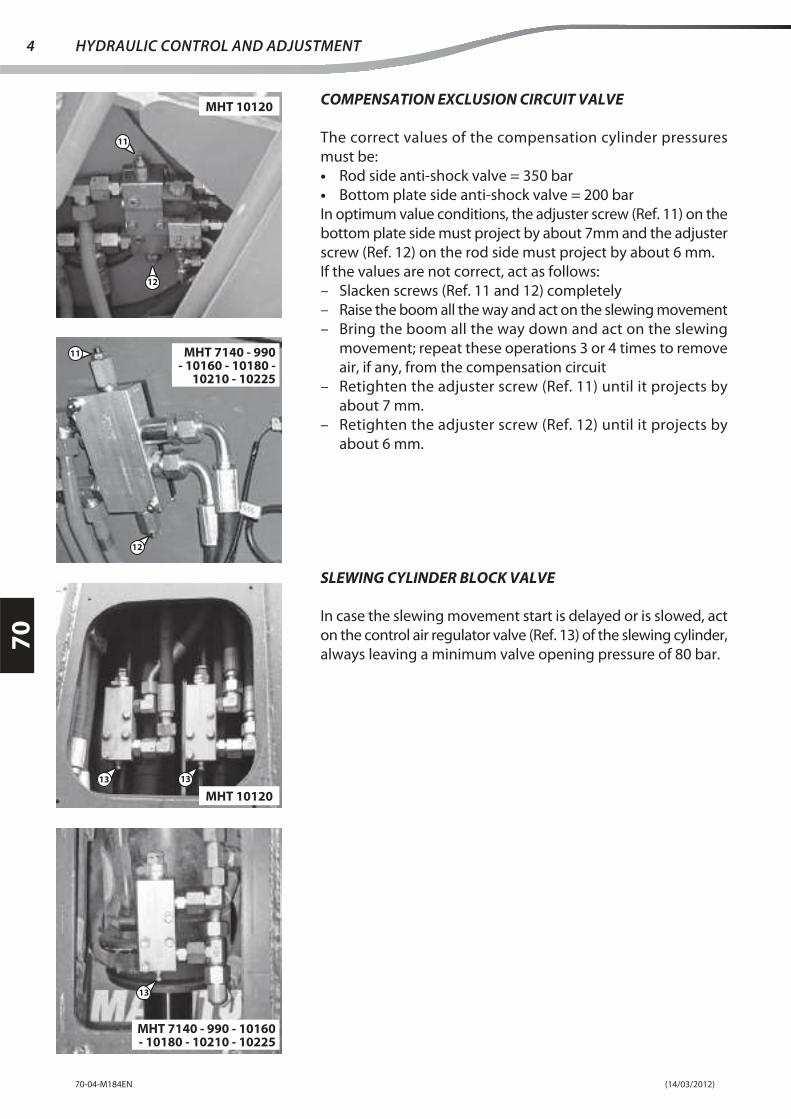
COMPENSATION EXCLUSION CIRCUIT VALVE
The correct values of the compensation cylinder pressures
must be:
• Rod side anti-shock valve = 350 bar
• Bottom plate side anti-shock valve = 200 bar
In optimum value conditions, the adjuster screw (Ref. 11) on the
bottom plate side must project by about 7mm and the adjuster
screw (Ref. 12) on the rod side must project by about 6 mm.
If the values are not correct, act as follows:
– Slacken screws (Ref. 11 and 12) completely
– Raise the boom all the way and act on the slewing movement
– Bring the boom all the way down and act on the slewing
movement; repeat these operations 3 or 4 times to remove
air, if any, from the compensation circuit
– Retighten the adjuster screw (Ref. 11) until it projects by
about 7 mm.
– Retighten the adjuster screw (Ref. 12) until it projects by
about 6 mm.
SLEWING CYLINDER BLOCK VALVE
In case the slewing movement start is delayed or is slowed, act
on the control air regulator valve (Ref. 13) of the slewing cylinder,
always leaving a minimum valve opening pressure of 80 bar.
11
12
11
12
MHT 10120
MHT 7140 - 990 - 10160 - 10180 -
10210 - 10225
MHT 10120
MHT 7140 - 990 - 10160 - 10180 - 10210 - 10225
13
13 13

(14/03/2012) 70-04-M184EN
70
5HYDRAULIC CONTROL AND ADJUSTMENT
LEVELLING
Check the levelling pressure by means of the pressure test
connector (Ref. 14) positioned on the pump and act on valve
(Ref. 15) to adjust the pressure.
Check the levelling until the cylinder limit stop is reached; the
value must be 205 bar.
DIRECTION
After adjusting the relief valve pressure to the correct value
(350 bar), check the pressure of the power steering (Ref. 16), by
means of the same pressure test connector and, if necessary,
act on valve (Ref. 17) to bring the value to 190 bar.
15
14
16
17

(14/03/2012)70-04-M184EN
70
6 HYDRAULIC CONTROL AND ADJUSTMENT
CHECKING THE HYDRAULIC PRESSURE OF THE LS CIRCUIT
– Check the hydraulic oil level.
– Dismantle the housing of the valves unit (Ref. 18) behind
the vehicle.
– Bring the oil to the operating temperature (50°) by performing
hydraulic movements.
Note: Below 1200 min-1 the valves unit pressure does not exceed
200 bar.
CHECKING AND SETTING THE STANDBY PRESSURE
(To make the connection also adjust the FR regulator)
– Connect the 0-600 bar digital pressure gauge to the pressure
test connector (Ref. 2).
– Insert the rev counter.
– With the engine running at minimum speed and without
making any movement, read the pressure value on the
pressure gauge.
– Standby pressure: 30 bar ± 3.
– If the pressure is not correct, turn the FR adjuster screw (Ref.
19) on the main pump. Tighten the screw to increase the
pressure, slacken it to reduce the pressure.
Note: If the pressure cannot be adjusted by means of this
operation, refer to the indications on page 2
– Using the rev counter, check the minimum engine speed:
850 min-1.
– Adjust, if necessary.
CHECKING THE ANTI-STALL VALVE
A - With the I.C. engine running at minimum speed, press the
manipulator button (accessories circuit).
- Progressively increase the engine rpm.
- Note down the number of rotations at which the pressure
changes from 200 to 350 bar (approx. 1200 ± 100 min-1).
B - With the I.C. engine running at maximum speed, press the
manipulator button (accessories circuit).
- Progressively reduce the I.C. engine rpm.
- Note down the number of rotations at which the pressure
changes from 350 to 200 bar (approx. 1200 ± 100 min-1).
Note: The anti-stall valve (Ref. 20) does not work correctly in
the following cases:
– The main pressure remains at 200 bar.
– The main pressure remains at 350 bar (engine stop at minimum).
– Pressure unstable.
18
2
19
20

(23/02/2012) 70-06-M184EN
70
HYDRAULIC COMPONENTS REMOVAL
page
PREPARATION AND SAFETY INSTRUCTIONS . . . . . . . . . . . . . . . . . . . . . . . . . . . . . . . . .2
DISMANTLING THE DIRECTIONAL CONTROL VALVE . . . . . . . . . . . . . . . . . . . . . . . . . .3
DISASSEMBLING THE CYLINDERS . . . . . . . . . . . . . . . . . . . . . . . . . . . . . . . . . . . . . . . . . . . .6
– DISASSEMBLING THE COMPENSATION CYLINDER. . . . . . . . . . . . . . . . . . . . . . . . . . . . . . . . 6
– DISASSEMBLING THE LIFT CYLINDER. . . . . . . . . . . . . . . . . . . . . . . . . . . . . . . . . . . . . . . . . . . . . 8
– DISASSEMBLING THE EXTENSION CYLINDER . . . . . . . . . . . . . . . . . . . . . . . . . . . . . . . . . . . . . 11
– REMOVING THE SLEWING CYLINDER . . . . . . . . . . . . . . . . . . . . . . . . . . . . . . . . . . . . . . . . . . . . . 12

(23/02/2012)70-06-M184EN
70
2 HYDRAULIC COMPONENTS REMOVAL
PREPARATION AND SAFETY INSTRUCTIONS
– Position the truck on a level surface.
– Raise the boom and set it in safety condition.
– Discharge the pressure from the hydraulic system.
– Deactivate the ignition key and disconnect the negative pole from the battery.
Specifi c tools:
- Crane for lifting (5000 kg. minimum).
DISMANTLING THE CYLINDERS AND DIRECTIONAL CONTROL VALVE
Only for MHT 10120
Only for
MHT 10210 and 10225

(23/02/2012) 70-06-M184EN
70
3HYDRAULIC COMPONENTS REMOVAL
DISMANTLING THE DIRECTIONAL CONTROL
VALVE
Slacken the screws (Ref. 1) and remove the upper collar (Ref. 2).
Slacken the screws (Ref. 3) and remove the bottom collar (Ref. 4).
The metal tubes (Ref. 5) can thus be removed to make it easy
to remove the directional control valve.
Mark all the pipes and connections with a marker pen, before
disassembling, to ensure correct positioning in the reassembly
phase.
Remove all the hydraulic pipes from the directional control
valve (Ref. 6).
bPlug all the pipes and connectors to prevent impurities
from contaminating the hydraulic circuit.
1
2
3
4
5
6

(23/02/2012)70-06-M184EN
70
4 HYDRAULIC COMPONENTS REMOVAL
Mark all the electrical connections with a marker pen, before
disassembling, to ensure correct positioning in the reassembly
phase.
Remove the electrical connections from the directional control
valve (Ref. 6).
Remove the collar (Ref. 7), positioned on the outside of the truck
frame, after slackening the screws (Ref. 8).
Disconnect the metal tube (Ref. 9) from the union (Ref. 10)
connected to the directional control valve.
6
8
7
9
10

(23/02/2012) 70-06-M184EN
70
5HYDRAULIC COMPONENTS REMOVAL
Remove the connector (Ref. 10) from the directional control valve.
Slacken the screws (Ref. 11) which block the directional control
valve (Ref. 6) on the truck frame.
Remove the directional control valve (Ref. 6) from the vehicle
using ropes and an overhead crane.
(Rif. 6) dalla macchina.
10
6
11
6
(23/02/2012)70-06-M184EN
70
6 HYDRAULIC COMPONENTS REMOVAL
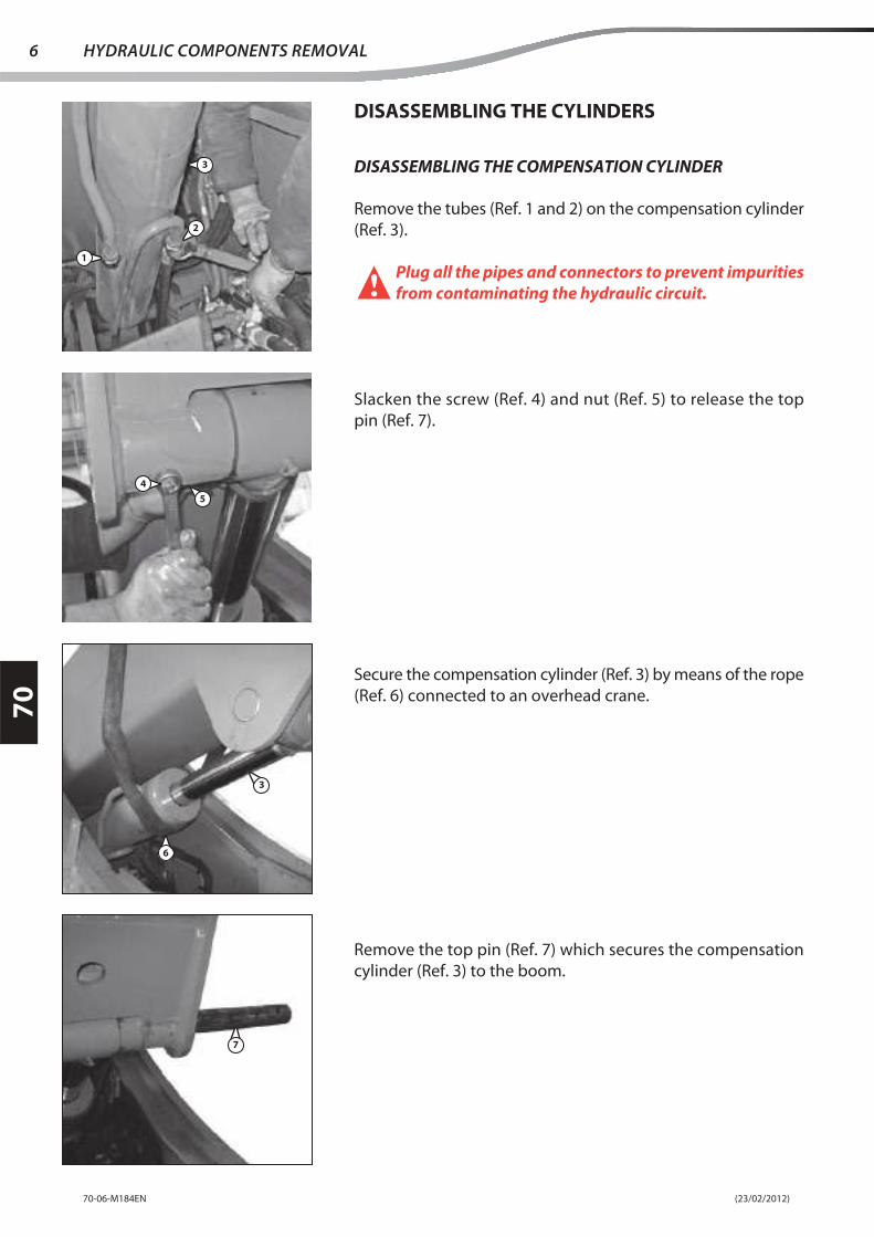
DISASSEMBLING THE CYLINDERS
DISASSEMBLING THE COMPENSATION CYLINDER
Remove the tubes (Ref. 1 and 2) on the compensation cylinder
(Ref. 3).
bPlug all the pipes and connectors to prevent impurities
from contaminating the hydraulic circuit.
Slacken the screw (Ref. 4) and nut (Ref. 5) to release the top
pin (Ref. 7).
Secure the compensation cylinder (Ref. 3) by means of the rope
(Ref. 6) connected to an overhead crane.
Remove the top pin (Ref. 7) which secures the compensation
cylinder (Ref. 3) to the boom.
2
1
4
5
3
6
7
3

(23/02/2012) 70-06-M184EN
70
7HYDRAULIC COMPONENTS REMOVAL
Using an overhead crane, lower the compensation cylinder (Ref.
3) until it comes to rest at the base of the truck frame.
Remove the grease nipple tube (Ref. 8) from the base of the
compensation cylinder (Ref. 3).
Slacken the screw (Ref. 9) and nut (Ref. 10) to release the bottom
pin (Ref. 11).
Remove the bottom pin (Ref. 11) which blocks the compensation
cylinder (Ref. 3) to the truck frame.
3
8
9
10
11

(23/02/2012)70-06-M184EN
70
8 HYDRAULIC COMPONENTS REMOVAL
With the help of an overhead crane, remove the compensation
cylinder (Ref.3) from the vehicle.
DISASSEMBLING THE LIFT CYLINDER
Place the boom (Ref. 1) on a supporting column
(Ref. 2) that can hold the weight.
Remove the grease nipple tube (Ref. 8) on the base of the lift
cylinder (Ref. 4).
Slacken the screw (Ref. 5) and nut (Ref. 6) to release the bottom
pin (Ref. 7).
3
2
3
4
6
5
7
1

(23/02/2012) 70-06-M184EN
70
9HYDRAULIC COMPONENTS REMOVAL
Remove the bottom pin (Ref. 7) which blocks the lifting cylinder
(Ref. 4) to the boom.
Note: It may be necessary to remove the wheel or steer it before
switching off the engine.
Slacken the screw (Ref. 8) and nut (Ref. 9) to release the top
pin (Ref. 10).
Secure the lift cylinder (Ref. 4) to an overhead crane and using
an extractor, remove the top pin (Ref. 10).
Place the lift cylinder (Ref. 4) on the truck frame.
7
9
8
104
4

(23/02/2012)70-06-M184EN
70
10 HYDRAULIC COMPONENTS REMOVAL
Remove the unions (Ref. 1) from the lift cylinder valve (Ref. 12).
bPlug all the pipes and connectors to prevent impurities
from contaminating the hydraulic circuit.
Remove the lift cylinder (Ref. 4) from the vehicle with the help
of an overhead crane.
FOR MHT 10210 AND 10225 ONLY
Vehicles MHT 10210 and 10225 are equipped with two lift
cylinders; the procedure for dismantling the grease nipples (Ref.
3) and bottom pin (Ref. 7) are the same as that described above.
Slacken the screw (Ref. 8) and nut (Ref. 9) to release the top
pin (Ref. 10).
Secure the fi rst lift cylinder (Ref. 13) to an overhead crane and
using an extractor, remove the top pin (Ref. 10) half way.
Place the fi rst lift cylinder (Ref. 13) on the truck frame.
Secure the second lift cylinder (Ref. 14) to an overhead crane
and remove the top pin (Ref. 10) completely.
Place the second lift cylinder (Ref. 14) on the truck frame.
With the help of an overhead crane, remove the lift cylinders
(Ref. 13 and 14) one at a time.
11 12
4
98
13
14
10

(23/02/2012) 70-06-M184EN
70
11HYDRAULIC COMPONENTS REMOVAL
DISASSEMBLING THE EXTENSION CYLINDER
Remove the Seeger ring (Ref. 1) from the front hinge pin (Ref.
2) of the extension cylinder.
Remove the front hinge pin (Ref. 2).
Raise the boom until the rear hinge pin (Ref. 3) is aligned and
accessible through the hole (Ref. 4) on the truck frame.
Remove the Seeger ring (Ref. 5) and remove the rear pin (Ref. 3).
1
2
2
3
4
5
3

(23/02/2012)70-06-M184EN
70
12 HYDRAULIC COMPONENTS REMOVAL
Remove the unions (Ref. 6) from the extension cylinder valve
(Ref. 7).
bPlug all the pipes and connectors to prevent impurities
from contaminating the hydraulic circuit.
Remove the extension cylinder (Ref. 10) from the vehicle with
the help of an overhead crane.
REMOVING THE SLEWING CYLINDER
Slacken the screws (Ref. 1) and remove the guard (Ref. 2) from
the head of the boom.
Unscrew the nut (Ref. 3).
6
7
8
1
2
3

(23/02/2012) 70-06-M184EN
70
13HYDRAULIC COMPONENTS REMOVAL
Remove the screw (Ref. 4).
Unscrew the ring nut (Ref. 5) to release the pin (Ref. 6) which
blocks the slewing cylinder (Ref. 7) rod on the quick-release
coupling (Ref. 8).
Place the quick-release coupling (Ref. 8) on a pallet truck (Ref.
9) and remove the pin (Ref. 6).
Remove the unions (Ref. 10) from the slewing cylinder valve
(Ref. 11).
bPlug all the pipes and connectors to prevent impurities
from contaminating the hydraulic circuit.
4
56
7
8
8
9
6
10
11

(23/02/2012)70-06-M184EN
70
14 HYDRAULIC COMPONENTS REMOVAL
Fit an eyebolt (Ref. 12) or a chain to the top of the slewing cylinder
(Ref. 7) through the slot present on the top of the boom head.
Slacken the screw (Ref. 13) and its nut to release the top pin
(Ref. 14) of the slewing cylinder.
Remove the top pin (Ref. 14) which blocks the slewing cylinder
on the boom head.
With the help of an overhead crane (Ref. 15), lower the cylinder
until it comes out of the boom head.
7
12
13
14
14
15

(23/02/2012) 70-06-M184EN
70
15HYDRAULIC COMPONENTS REMOVAL
Remove the slewing cylinder (Ref. 7) from the vehicle.
FOR MHT 10120 ONLY
The MHT 10120 vehicle is equipped with two slewing cylinders;
the procedure for removing the quick-release coupling (Ref.
8) and the pin (Ref. 6) which blocks the rods of the slewing
cylinders to the quick-release coupling is the same as that
described above.
Slacken the screw (Ref. 13) and its nut to release the top pin
(Ref. 14) of the slewing cylinders.
Secure the fi rst slewing cylinder (Ref. 16) to an overhead crane,
remove the top pin (Ref. 14) half way and rest the cylinder (Ref.
16) on the ground.
Secure the second slewing cylinder (Ref. 17) to an overhead
crane, remove the top pin (Ref. 14) completely and rest the
cylinder (Ref. 17) on the ground.
7
16 17

(23/02/2012)70-06-M184EN
70
16 HYDRAULIC COMPONENTS REMOVAL

(23/03/2012) 70-07-M184EN
70
HYDRAULIC COMPONENTS REFIT
page
PREPARATION AND SAFETY INSTRUCTIONS . . . . . . . . . . . . . . . . . . . . . . . . . . . . . . . . .2
REASSEMBLING THE CYLINDERS. . . . . . . . . . . . . . . . . . . . . . . . . . . . . . . . . . . . . . . . . . . . .3
– REASSEMBLING THE SLEWING CYLINDER . . . . . . . . . . . . . . . . . . . . . . . . . . . . . . . . . . . . . . . . 3
– REASSEMBLING THE EXTENSION CYLINDER . . . . . . . . . . . . . . . . . . . . . . . . . . . . . . . . . . . . . . 6
– REASSEMBLING THE LIFT CYLINDER . . . . . . . . . . . . . . . . . . . . . . . . . . . . . . . . . . . . . . . . . . . . . 7
– REASSEMBLING THE COMPENSATION CYLINDER. . . . . . . . . . . . . . . . . . . . . . . . . . . . . . . . . 10
REASSEMBLING THE DIRECTIONAL CONTROL VALVE . . . . . . . . . . . . . . . . . . . . . . . . .12

(23/03/2012)70-07-M184EN
70
2 HYDRAULIC COMPONENTS REFIT
PREPARATION AND SAFETY INSTRUCTIONS
– Position the truck on a level surface.
– Raise the boom and set it in safety condition.
– Discharge the pressure from the hydraulic system.
– Deactivate the ignition key and disconnect the negative pole from the battery.
Specifi c tools:
- Crane for lifting (5000 kg. minimum).
REASSEMBLING THE CYLINDERS AND DIRECTIONAL CONTROL VALVE
Only for MHT 10120
Only for
MHT 10210 and 10225

(23/03/2012) 70-07-M184EN
70
3HYDRAULIC COMPONENTS REFIT
REASSEMBLING THE CYLINDERS
REASSEMBLING THE SLEWING CYLINDER
Insert the chain of the overhead crane (Ref. 1) in the slot on the
top of the boom and fi x the chain to the head of the slewing
cylinder
(Ref. 2) or to an eyebolt fi tted on the cylinder.
With the help of an overhead crane lift the slewing cylinder
(Ref. 2) at the top of the boom.
Insert the upper hinge pin (Ref. 3) to block the slewing cylinder
to the boom.
Fit the screw (Ref. 4) and its nut to block the top pin (Ref. 3) of
the slewing cylinder.
3
1
2
4
3

(23/03/2012)70-07-M184EN
70
4 HYDRAULIC COMPONENTS REFIT
Reconnect the hydraulic tubes (Ref. 5) on the slewing cylinder
valve (Ref. 6), taking care to position these correctly, according
to the markings made during the disassembly.
Use a pallet truck (Ref. 7) to bring the quick-release coupling
(Ref. 8) to its position on the boom.
Insert the hinge pin (Ref. 9) of the quick-release coupling on
the boom.
Insert the pin (Ref. 11) and screw the nut (Ref. 10) on the quick-
release coupling (Ref. 8).
Fit the screw (Ref. 12).
8
7
9
5
6
1011
2
8
12

(23/03/2012) 70-07-M184EN
70
5HYDRAULIC COMPONENTS REFIT
Screw the nut (Ref. 13).
Fit the guard (Ref. 14) by means of the screws (Ref. 15).
FOR MHT 10120 ONLY
The MHT 10120 vehicle is equipped with two slewing cylinders.
Using an overhead crane lift the fi rst slewing cylinder (Ref. 16)
at the top of the boom, insert the top pin (Ref. 3) half way to
block the cylinder (Ref. 16).
Using an overhead crane lift the fi rst slewing cylinder (Ref. 17)
at the top of the boom, insert the top pin (Ref. 3) completely
to block the cylinder (Ref. 17).
The procedure for refi tting the quick-release coupling (Ref. 8)
and pin (Ref. 11) which blocks the rods of the slewing cylinders to
the quick-release coupling is the same as that described above.
15
14
13
16 17

(23/03/2012)70-07-M184EN
70
6 HYDRAULIC COMPONENTS REFIT
REASSEMBLING THE EXTENSION CYLINDER
Using an overhead crane reposition the extension cylinder
(Ref. 1) on the vehicle.
Reconnect the hydraulic tubes (Ref. 2) on the extension cylinder
valve (Ref. 3), taking care to position these correctly, according
to the markings made during the disassembly.
Raise the boom until the hole (Ref. 5) for the rear hinge pin is
visible through the hole (Ref. 4) on the truck frame.
Refi t the hinge pin (Ref. 6) and block by means of the Seeger
ring (Ref. 7).
5
4
7
6
1
2
3

(23/03/2012) 70-07-M184EN
70
7HYDRAULIC COMPONENTS REFIT
Insert the front hinge pin (Ref. 8).
Refi t the Seeger ring (Ref. 9) on the front hinge pin (Ref. 8) of
the extension cylinder.
REASSEMBLING THE LIFT CYLINDER
Reposition the lift cylinder (Ref. 1) on the vehicle with the help
of an overhead crane.
Reconnect the hydraulic tubes (Ref. 2) on the lift cylinder valve
(Ref. 3), taking care to position these correctly, according to the
markings made during the disassembly.
9
8
8
1
2 3

(23/03/2012)70-07-M184EN
70
8 HYDRAULIC COMPONENTS REFIT
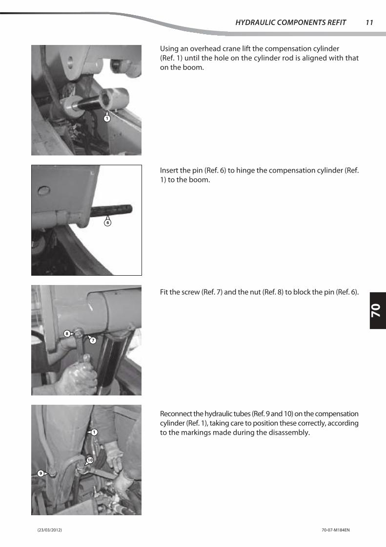
Using an overhead crane raise the lift cylinder
(Ref. 1) until the hole on the cylinder rod is aligned with that
on the boom.
Insert the hinge pin (Ref. 4) of the lift cylinder (Ref. 1) on the
boom.
Fit the screw (Ref. 5) and the nut (Ref. 6) to block the top pin
(Ref. 4).
Insert the bottom pin (Ref. 7) to hinge the lift cylinder (Ref. 1)
to the boom.
41
1
7
6
5

(23/03/2012) 70-07-M184EN
70
9HYDRAULIC COMPONENTS REFIT
Fit the screw (Ref. 8) and the nut (Ref. 9) to block the bottom
pin (Ref. 7).
Refit the grease nipple tube (Ref. 8) on the base of the lift
cylinder (Ref. 1).
Remove the supporting column (Ref. 11) which supported the
boom (Ref. 12).
FOR MHT 10210 AND 10225 ONLY
Vehicles MHT 10210 and 10225 are equipped with two lift
cylinders.
Using an overhead crane, reposition the fi rst lift cylinder (Ref.
13) on the vehicle, insert the top pin (Ref. 4) half way to block
the cylinder (Ref. 13).
Using an overhead crane, reposition the second lift cylinder
(Ref. 14) on the vehicle, insert the top pin (Ref. 4) completely
to block the cylinder (Ref. 14).
The procedure for refitting the hydraulic tubes (Ref. 2), the
bottom pin (Ref. 7) and grease nipple (Ref. 10) are the same as
that described above.
Fit the screw (Ref. 15) and the nut (Ref. 16) to block the top pin
(Ref. 4).
10
9
8
1
11
1314
1615
4
12

(23/03/2012)70-07-M184EN
70
10 HYDRAULIC COMPONENTS REFIT
REASSEMBLING THE COMPENSATION CYLINDER
With the help of an overhead crane, reposition the compensation
cylinder (Ref. 1) on the vehicle.
Insert the pin (Ref. 2) to hinge the compensation cylinder (Ref.
1) to the truck frame.
Fit the screw (Ref. 3) and the nut (Ref. 4) to block the pin (Ref. 2).
Refit the grease nipple tube (Ref. 5) on the base of the
compensation cylinder (Ref. 1).
1
2
3
4
5
(23/03/2012) 70-07-M184EN
70
11HYDRAULIC COMPONENTS REFIT
Using an overhead crane lift the compensation cylinder
(Ref. 1) until the hole on the cylinder rod is aligned with that
on the boom.
Insert the pin (Ref. 6) to hinge the compensation cylinder (Ref.
1) to the boom.
Fit the screw (Ref. 7) and the nut (Ref. 8) to block the pin (Ref. 6).
Reconnect the hydraulic tubes (Ref. 9 and 10) on the compensation
cylinder (Ref. 1), taking care to position these correctly, according
to the markings made during the disassembly.
1
6
8
7
10
9
1

(23/03/2012)70-07-M184EN
70
12 HYDRAULIC COMPONENTS REFIT
REASSEMBLING THE DIRECTIONAL CONTROL
VALVE
Reposition the directional control valve on the vehicle using
ropes and an overhead crane.
(Rif. 1) sulla macchina.
Block the directional control valve (Ref. 1) on the truck frame
by means of the screws (Ref. 2).
Refi t the union (Ref. 3) on the directional control valve from the
outer part of the truck frame.
Refi t the metal tube (Ref.4) on the union (Ref. 3).
1
1
2
3
4
3

(23/03/2012) 70-07-M184EN
70
13HYDRAULIC COMPONENTS REFIT
Refi t the collar (Ref. 5), positioned on the outside of the truck
frame, tightening the screws (Ref. 6).
Reconnect the electrical connections on the directional control
valve (Ref. 1), taking care to position these correctly, according
to the markings made in the disassembly step.
Reconnect all the hydraulic pipes on the directional control valve
(Ref. 1), taking care to reposition them correctly, by following
the markings made in the disassembly phase.
Secure the metal tubes (Ref. 7) to the truck frame by fi tting the
bottom collar (Ref. 8) and screws (Ref. 9).
1
6
5
1
9
8
7

(23/03/2012)70-07-M184EN
70
14 HYDRAULIC COMPONENTS REFIT
Refi t the upper collar (Ref. 10) by means of the screws (Ref. 11).
11
10

(20/02/2013) 70-09-M184EN
70
HYDRAULIC SPECIFIC TOOLING
page
PRESSURE GAUGES STANDARD BOX . . . . . . . . . . . . . . . . . . . . . . . . . . . . . . . . . . . . . . . . .2
DIGITAL PRESSURE GAUGE BOX . . . . . . . . . . . . . . . . . . . . . . . . . . . . . . . . . . . . . . . . . . . . .3
– FUNCTIONS: . . . . . . . . . . . . . . . . . . . . . . . . . . . . . . . . . . . . . . . . . . . . . . . . . . . . . . . . . . . . . . . . . . . . . 3
SAFETY BLOCK FOR LIFT PISTON. . . . . . . . . . . . . . . . . . . . . . . . . . . . . . . . . . . . . . . . . . . . .4

(20/02/2013)70-09-M184EN
70
2 HYDRAULIC SPECIFIC TOOLING
Pressure gauges standard box . . . . . . . . . . . . . . . . . . . . . . . . . . . . . . . . . . . . . . . . . . . . . . . . . . . . . . . . . 549671
Consisting of:
1 - 1 1/9 bar Pressure gauge . . . . . . . . . . . . . . . . . . . . . . . . . . . . . . . . . . . . . . . . . . . . . . . . . . . . . . . . 549882
2 - 1 0/40 bar Pressure gauge . . . . . . . . . . . . . . . . . . . . . . . . . . . . . . . . . . . . . . . . . . . . . . . . . . . . . . . 549883
3 - 2 0/60 bar Pressure gauges . . . . . . . . . . . . . . . . . . . . . . . . . . . . . . . . . . . . . . . . . . . . . . . . . . . . . . . . 549884
4 - 1 0/400 bar Pressure gauge . . . . . . . . . . . . . . . . . . . . . . . . . . . . . . . . . . . . . . . . . . . . . . . . . . . . . . 549885
5 - 2 0/600 bar Pressure gauges . . . . . . . . . . . . . . . . . . . . . . . . . . . . . . . . . . . . . . . . . . . . . . . . . . . . . . . 549886
6 - 4 standard hoses . . . . . . . . . . . . . . . . . . . . . . . . . . . . . . . . . . . . . . . . . . . . . . . . . . . . . . . . . . . . . . 549887
7 - 2 hoses for Maniscopic . . . . . . . . . . . . . . . . . . . . . . . . . . . . . . . . . . . . . . . . . . . . . . . . . . . . . . . . 549888
8 - 7 Pressure gauge connectors . . . . . . . . . . . . . . . . . . . . . . . . . . . . . . . . . . . . . . . . . . . . . . . . . . . . . . 549889
1 2 3 3 4 5 5 6
78
PRESSURE GAUGES STANDARD BOX
The box contains all the components necessary for measuring
the pressures on all Manitou products.
(20/02/2013) 70-09-M184EN
70
3HYDRAULIC SPECIFIC TOOLING
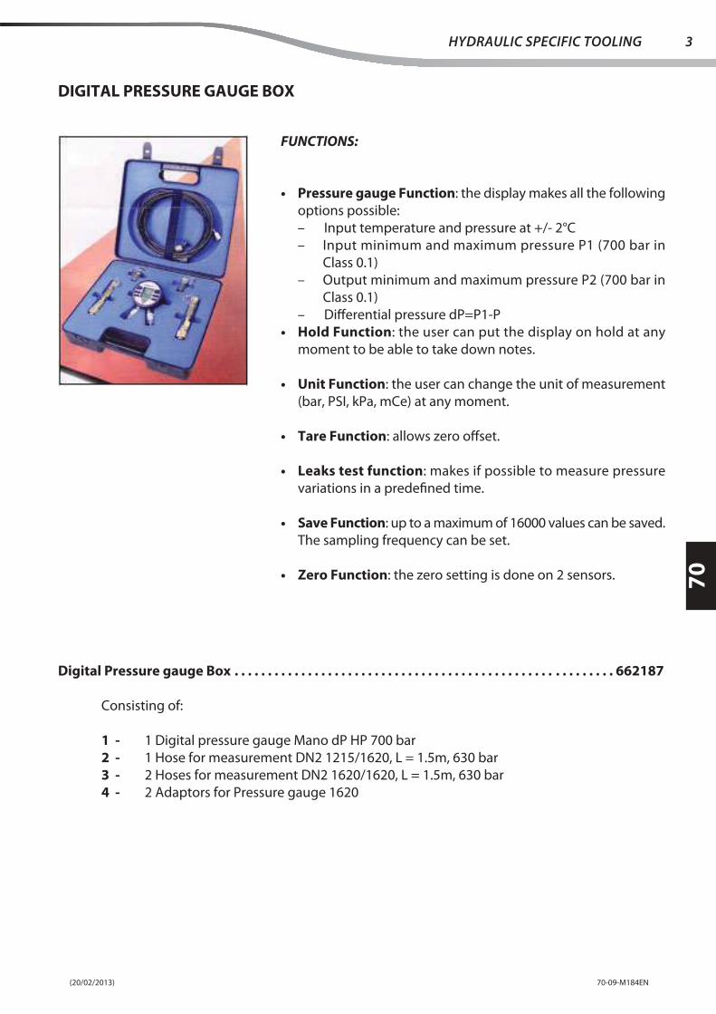
Digital Pressure gauge Box . . . . . . . . . . . . . . . . . . . . . . . . . . . . . . . . . . . . . . . . . . . . . . . . . . . . . . . . . 662187
Consisting of:
1 - 1 Digital pressure gauge Mano dP HP 700 bar
2 - 1 Hose for measurement DN2 1215/1620, L = 1.5m, 630 bar
3 - 2 Hoses for measurement DN2 1620/1620, L = 1.5m, 630 bar
4 - 2 Adaptors for Pressure gauge 1620
DIGITAL PRESSURE GAUGE BOX
FUNCTIONS:
• Pressure gauge Function: the display makes all the following
options possible:
– Input temperature and pressure at +/- 2°C
– Input minimum and maximum pressure P1 (700 bar in
Class 0.1)
– Output minimum and maximum pressure P2 (700 bar in
Class 0.1)
– Diff erential pressure dP=P1-P
• Hold Function: the user can put the display on hold at any
moment to be able to take down notes.
• Unit Function: the user can change the unit of measurement
(bar, PSI, kPa, mCe) at any moment.
• Tare Function: allows zero off set.
• Leaks test function: makes if possible to measure pressure
variations in a predefi ned time.
• Save Function: up to a maximum of 16000 values can be saved.
The sampling frequency can be set.
• Zero Function: the zero setting is done on 2 sensors.

(20/02/2013)70-09-M184EN
70
4 HYDRAULIC SPECIFIC TOOLING
SAFETY BLOCK FOR LIFT PISTON
Used for setting the raised boom in safety
condition.
Prevents accidental falling of the boom in case
of depressurization of the system.
Safety block for MHT 990 - 7140 - 10120 - 10160 - 10180. . . . . . . . . . . . . . . . . . . . . . . . . . . . . . . . . . 909390
Safety block for MHT 10210 - 10225. . . . . . . . . . . . . . . . . . . . . . . . . . . . . . . . . . . . . . . . . . . . . . . . . . 909398

ELECTRICITY
- ELECTRICAL CHARACTERISTICS AND
SPECIFICATIONS
- ELECTRICAL SCHEMATIC DIAGRAMS
- ELECTRICAL COMPONENTS LOCATION
- ELECTRICAL CONTROL AND ADJUSTMENT
- ELECTRICAL SPECIFIC TOOLING
80


(23/07/2012) 80-01-M184EN
80
ELECTRICAL CHARACTERISTICS AND
SPECIFICATIONS
page
CONNECTORS . . . . . . . . . . . . . . . . . . . . . . . . . . . . . . . . . . . . . . . . . . . . . . . . . . . . . . . . . . . . . . . . . . . . .2
(23/07/2012)80-01-M184EN
80
2ELECTRICAL CHARACTERISTICS AND SPECIFICATIONS
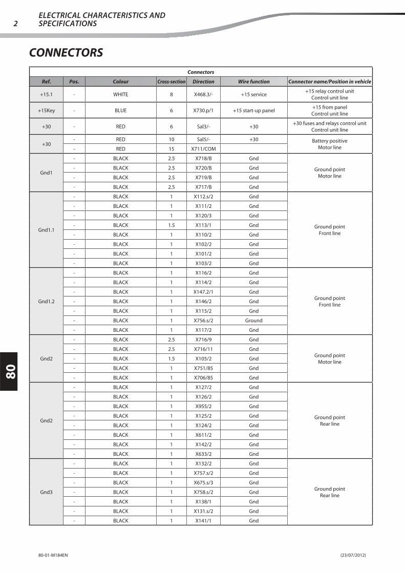
Connectors
Ref. Pos. Colour Cross-section Direction Wire function Connector name/Position in vehicle
+15.1 - WHITE 8 X468.3/- +15 service+15 relay control unit
Control unit line
+15Key - BLUE 6 X730.p/1 +15 start-up panel+15 from panel
Control unit line
+30 - RED 6 Sal3/- +30+30 fuses and relays control unit
Control unit line
+30- RED 10 Sal5/- +30 Battery positive
Motor line- RED 15 X711/COM
Gnd1
- BLACK 2.5 X718/B Gnd
Ground point
Motor line
- BLACK 2.5 X720/B Gnd
- BLACK 2.5 X719/B Gnd
- BLACK 2.5 X717/B Gnd
Gnd1.1
- BLACK 1 X112.s/2 Gnd
Ground point
Front line
- BLACK 1 X111/2 Gnd
- BLACK 1 X120/3 Gnd
- BLACK 1.5 X113/1 Gnd
- BLACK 1 X110/2 Gnd
- BLACK 1 X10²/2 Gnd
- BLACK 1 X101/2 Gnd
- BLACK 1 X10³/2 Gnd
Gnd1.2
- BLACK 1 X116/2 Gnd
Ground point
Front line
- BLACK 1 X114/2 Gnd
- BLACK 1 X147.2/1 Gnd
- BLACK 1 X146/2 Gnd
- BLACK 1 X115/2 Gnd
- BLACK 1 X756.s/2 Ground
- BLACK 1 X117/2 Gnd
Gnd2
- BLACK 2.5 X716/9 Gnd
Ground point
Motor line
- BLACK 2.5 X716/11 Gnd
- BLACK 1.5 X10⁵/2 Gnd
- BLACK 1 X751/85 Gnd
- BLACK 1 X706/85 Gnd
Gnd2
- BLACK 1 X127/2 Gnd
Ground point
Rear line
- BLACK 1 X126/2 Gnd
- BLACK 1 X955/2 Gnd
- BLACK 1 X125/2 Gnd
- BLACK 1 X124/2 Gnd
- BLACK 1 X611/2 Gnd
- BLACK 1 X142/2 Gnd
- BLACK 1 X633/2 Gnd
Gnd3
- BLACK 1 X132/2 Gnd
Ground point
Rear line
- BLACK 1 X757.s/2 Gnd
- BLACK 1 X675.s/3 Gnd
- BLACK 1 X758.s/2 Gnd
- BLACK 1 X138/1 Gnd
- BLACK 1 X131.s/2 Gnd
- BLACK 1 X141/1 Gnd
CONNECTORS

(23/07/2012) 80-01-M184EN
80
3ELECTRICAL CHARACTERISTICS AND
SPECIFICATIONS
Connectors
Ref. Pos. Colour Cross-section Direction Wire function Connector name/Position in vehicle
Gnd4.1
- BLACK 1.5 X119.2/1 Gnd
Ground point
Driver's seat line
- BLACK 1.5 X188/1 Gnd
- BLACK 1 X760.s/2 Ground
- BLACK 1.5 X473/1 Gnd
- BLACK 1 X167/1 Gnd
- BLACK 1 X224.s/B Gnd
- BLACK 1 X196/2 Gnd
Gnd4.2
- BLACK 1.5 X164.s/13 Gnd
Ground point
Driver's seat line
- BLACK 1.5 X164.s/4 Gnd
- BLACK 1.5 X164.s/12 Gnd
- BLACK 1 X732.s/C3 Gnd
- BLACK 1 X732.s/C1 Gnd
- BLACK 1.5 X206.s/13 Gnd
- BLACK 1 Sal48/- Gnd
Gnd4.3
- BLACK 1.5 X464/3 Gnd
Ground point
Driver's seat line
- BLACK 2.5 X204.3/1 Gnd
- BLACK 1.5 X178.1/2 Gnd
- BLACK 1.5 X186.s/11 Gnd
- BLACK 1 X467/6 Ground
- BLACK 1 X207/8 Gnd
Gnd4.4
- BLACK 2.5 X163.s/2 Gnd
Ground point
Driver's seat line
- BLACK 1 X172.s/2 Gnd
- BLACK 2.5 X163.s/4 Gnd
- BLACK 1 X822/4 Gnd
- BLACK 1 X210/1 Gnd
- BLACK 1.5 X175/5 Gnd
Gnd5.1
- BLACK 1.5 X162.p/8 Gnd
Ground point
Driver's seat line
- BLACK 1.5 X162.p/9 Gnd
- BLACK 1.5 X162.p/7 Gnd
- BLACK 1.5 X162.p/5 Gnd
- BLACK 2.5 X731.s/9 Gnd
Gnd5.2
- BLACK 2.5 X825.3/4 Gnd
Ground point
Driver's seat line
- BLACK 1 X256.p/16 Gnd
- BLACK 1 X256.p/11 Gnd
- BLACK 1 X825.1/21 Gnd
- BLACK 2.5 X174/A Gnd
- BLACK 0.5 X476/1 Gnd
Sa1
- GREEN 0.5 X100/15 CompressorCompressor
Air conditioning kit- GREEN 0.5 X10²/A5 Compressor
- GREEN 0.5 X110/4 Compressor
Sa1
- GREY/BLACK 1 X957/30 +15 Platform
+15 Platform
Radio gripper platform line
- GREY/BLACK 1 X256.s/10 +15 Platform
- GREY/BLACK 1 X901.1/9 Radio selector power supply
- GREY 1.5 X900/C3 +15 gripper sol.v
- GREY 1.5 X916.s/A +15 Platform
- GREY/BLACK 1 X902/9 +15 Platform
Sa1 - WHITE-BLACK 0.5 XC1/T1 ShieldShield
Platform arm extension

(23/07/2012)80-01-M184EN
80
4ELECTRICAL CHARACTERISTICS AND SPECIFICATIONS
Connectors
Ref. Pos. Colour Cross-section Direction Wire function Connector name/Position in vehicle
Sa2
- RED-BLACK 0.5 X10²/A7
+ Positive
Air conditioning kit
- RED-BLACK 0.5 X10²/B4
- RED-BLACK 1.5 X10²/C8
- RED-BLACK 1.5 X10²/A2
- RED-BLACK 0.5 X10⁵/3 +12V
- RED-BLACK 0.5 X10³/86 +12V
- RED-BLACK 2.5 X10³/30 +12V
- RED-BLACK 0.5 X100/6 +Key
- RED-BLACK 2.5 X176/1 +12V
- RED-BLACK 0.5 X100/16 + Lights
Sa2
- GREEN 0.35 X916.s/D Can L
+15 Platform
Radio gripper platform line
- GREEN 0.35 X911/B Can L
- GREEN 0.35 X914.1/16 Can L
- GREEN 0.35 X256.s/5 Can L
Sa3
- BLACK 1 Sa7/- Ground
Ground
Radio gripper platform line
- BLACK 0.5 X900/A6 Ground
- BLACK 1 X957/85 Ground
- BLACK 0.5 X900/B5 Ground
- BLACK 0.5 X900/A5 Ground
- BLACK 0.5 X900/B3 Ground
Sa3-5
- BLACK 2.5 X10⁹/A Ground
- Negative
Air conditioning kit
- BLACK 1.5 X104.2/2 Ground
- BLACK 2.5 X10⁷/2 Ground
- BLACK 0.5 X100/7 Ground
- BLACK 0.5 X10⁵/2 Ground
- BLACK 1.5 X104.1/2 Ground
- BLACK 2.5 X204.3/1 Ground
Sa4
- RED 1.5 X10²/C5
-
Air conditioning kit
- RED 0.5 X10²/A4
- RED 0.5 X10²/B6
- RED 0.5 X100/8 + Battery
- RED 2.5 X10²/C1
- RED 2.5 X10⁷/1
Sa4
- WHITE 0.35 X916.s/C Can H
CAN H
Radio gripper platform line
- WHITE 0.35 X256.s/4 Can H
- WHITE 0.35 X911/A Can H
- WHITE 0.35 X914.1/15 Can H
Sa5
- BLACK 1.5 X910.s/5 Gripper groundGround
Radio gripper platform line- BLACK 2 X916.s/G Ground
- BLACK 1.5 X256.s/16 Ground
Sa6
- WHITE 1.5 X256.s/7 Cab mushroom enabling
Emergency mushroom out
Radio gripper platform line
- WHITE 1.5 X914.2/25 Radio mushroom out
- WHITE 1.5 X901.1/7 Mushroom out
- WHITE 1.5 X956.s/1 Mushroom Out

(23/07/2012) 80-01-M184EN
80
5ELECTRICAL CHARACTERISTICS AND
SPECIFICATIONS
Connectors
Ref. Pos. Colour Cross-section Direction Wire function Connector name/Position in vehicle
Sa7
- BLACK 1 X954/2 Ground
Ground
Radio gripper platform line
- BLACK 1.5 X256.s/11 Ground
- BLACK 1 X914.2/32 Ground
- BLACK 1 X915/5 Ground
- BLACK 1 Sa3/- Ground
- BLACK 1 X903/10 Ground
- BLACK 1 X907/2 Ground
- BLACK 1 X904/2 Ground
- BLACK 1 X908/2 Ground
- BLACK 1 X953/10 Ground
- BLACK 1 X905.s/2 Ground
- BLACK 1 X906.s/2 Ground
Sa8
- GREY-WHITE 1.5 X950.s/1 Mushroom In
Mushroom In
Radio gripper platform line- GREY-WHITE 1.5 X916.s/F
Platform mushroom
enabling
- GREY-WHITE 1.5 X256.s/6 Cab mushroom In
Sa9
- YELLOW-RED 1 X950.s/3 +VE+VE
Radio gripper platform line- YELLOW-RED 1 X955.s/1 +VE
- YELLOW-RED 1 X256.s/17 +VE
Sal1
- PINK-YELLOW 1 X755.s/1 Diff erential micro p.supply
Sensors power supply
Front line- PINK-YELLOW 1 X118/1
Front axle alignment sensor
p.supply
- PINK-YELLOW 1 X160.s/4 Sensors p.supply
Sal1
- WHITE 8 X468.3/- +15
+15 start-up panel
Control unit line
- WHITE 4 X474/4a +15
- WHITE 1.5 X474/7a +15
- WHITE 1 X474/9a +15
- WHITE 1.5 X474/8a +15
- WHITE 1 X474/10a +15
- WHITE 1 X474/6a +15
Sal2
- YELLOW-BLACK 1 X756.s/1 RH front side marker lampPosition lights
Front line- YELLOW-BLACK 1 X113/4 RH front position lights
- YELLOW-BLACK 1 X160.s/25 RH position light
Sal2
- RED 4 Sal3/- +30
+30
Control unit line
- RED 1 X474/1a +30
- RED 1 X474/3a +30
- RED 1 X474/2a +30
- RED 1 X474/5a +30
Sal2
- WHITE-GREEN 1.5 X720.s/N +15 Ignition+15 ignition
Motor line- WHITE-GREEN 1 X721.s/3 86 preheating relay
- WHITE-GREEN 1.5 X716/15 +15 Ignition
Sal3
- RED 6 X730.p/2 +30+30
Control unit line- RED 4 Sal2/- +30
- RED 6 +30/- +30
Sal4
- BLACK 1 X5.s/11 Gnd
Gnd
Control unit line
- BLACK 2.5 X731.p/9 Gnd
- BLACK 1 X474/85 Gnd
- BLACK 1 X468.2/2 Gnd
- BLACK 1 X8.s/14 Gnd

(23/07/2012)80-01-M184EN
80
6ELECTRICAL CHARACTERISTICS AND SPECIFICATIONS
Connectors
Ref. Pos. Colour Cross-section Direction Wire function Connector name/Position in vehicle
Sal5
- LIGHT BLUE 2.5 X731.p/1 +VP MC2M
Power supply + VP
Control unit line
- LIGHT BLUE 4 X474/87 P.supply +VP
- LIGHT BLUE 2.5 X731.p/10 P.supply +VP MC2M
- LIGHT BLUE 2.5 X731.p/12 P.supply +VP MC2M
Sal5
- RED 10 +30/- +30
+30
Motor line
- RED 6 X735/30 30 Electric fans 3 and 4 relay
- RED 6 X706/30 30 Electric fans 1 and 2 relay
- RED 2.5 X709/1P.supply + 30 fuse p.s ECU
Mercedes
Sal12
- YELLOW-RED 1 X128.s/12 Reversing light
Reversing light
Rear line
- YELLOW-RED 1 X132/1 Reversing buzzer
- YELLOW-RED 1 X141/3 RH reversing light
- YELLOW-RED 1 X675.s/2 Trailer reversing light
- YELLOW-RED 1 X138/3 LH reversing light
Sal13
- WHITE/RED 1 X128.s/13 Rear fog lamp
Rear fog lamp
Rear line
- WHITE/RED 1 X141/6 RH rear fog lamp
- WHITE/RED 1 X138/6 LH rear fog lamp
- WHITE/RED 1 X675.s/8 Trailer rear fog lamp
Sal14
- RED-YELLOW 1 X128.s/14 Stop lights
Stop light
Rear line
- RED-YELLOW 1 X675.s/6 Trailer stop light
- RED-YELLOW 1 X138/5 LH stop light
- RED-YELLOW 1 X141/5 RH stop light
Sal15
- BROWN-BLACK 1 X128.s/15 Boom micro p.supply
Micro p.supply
Rear line
- BROWN-BLACK 1 X140/1 Boom micro p.supply
- BROWN-BLACK 1 X139/2Boom retracted micro
p.supply
Sal17
- YELLOW 1 X141/2 RH rear position light
RH rear position light
Rear line
- YELLOW 1 X675.s/7 Trailer RH position light
- YELLOW 1 X758.s/1 RH rear side marker lamp
- YELLOW 1 X128.s/17 RH rear position light
Sal18
- LIGHT BLUE 1 X141/4 RH direction lightRH direction light
Rear line- LIGHT BLUE 1 X675.s/4 RH direction light
- LIGHT BLUE 1 X128.s/4 RH direction light
Sal19
- ORANGE-BLUE 1 X186.s/12 Rear fog lamp switch p.s.Rear fog lamp switch and indicator
stalk switch power supply
Driver's seat line
- ORANGE-BLUE 1.5 X732.s/A1 Indicator stalk lights p.s
- ORANGE-BLUE 1.5 X191/1 Indicator stalk lights p.s
Sal20
- BLUE 1 X675.s/1 LH direction lightLH direction light
Rear line- BLUE 1 X138/4 LH direction light
- BLUE 1 X128.s/18 LH rear direction light
Sal21
- YELLOW-BLACK 1 X128.s/16 LH rear position light
LH rear position light
Rear line
- YELLOW-BLACK 1 X131.s/1 License plate light
- YELLOW-BLACK 1 X757.s/1 LH rear side marker lamp
- YELLOW-BLACK 1 X138/2 LH rear position light
- YELLOW-BLACK 1 X675.s/5 Trailer LH position light
Sal21
- GREEN 2.5 X176/1 Front fan p.supply
+15 heating
Driver's seat line
- GREEN 4 X731.s/11 +15 heating
- GREEN 1.5 X175/4 +15 heating panel
- GREEN 1 - 30 compressor relay
Sal23- PINK ORANGE GREY 0.32 X851/1 Shield CAN shield
Rear line- PURPLE 1 X128.s/25 SCH

(23/07/2012) 80-01-M184EN
80
7ELECTRICAL CHARACTERISTICS AND
SPECIFICATIONS
Connectors
Ref. Pos. Colour Cross-section Direction Wire function Connector name/Position in vehicle
Sal24
- GREY-GREEN 1 X128.s/29 Boom angle sensor p.supplyBoom angle sensor power supply
Rear line- GREY-GREEN 1 X952/2 Boom sensor p.supply
- GREY-GREEN 1 X952/5 Boom sensor p.supply
Sal24
- GREY-BLACK 1 X211/5 Mix. bucket switch p.s
Mixer bucket double and triple
output and reverse fan power supply
Driver's seat line
- GREY-BLACK 1 X212/3 Mix. bucket switch p.s
- GREY-BLACK 1.5 X733.s/B_D1Mix. bucket switch and
double/triple out. p.s
- GREY-BLACK 1 X212/4 Mix. bucket switch p.s
- GREY-BLACK 1 X212/1 Mix. bucket switch p.s
Sal25
- BLUE-BLACK 1 X128.s/30 Boom sensor GndBoom sensor Gnd
Rear line- BLUE-BLACK 1 X952/4 Gnd
- BLUE-BLACK 1 X952/1 Gnd
Sal28
- LIGHT BLUE 1 X167/10 Deadman's switch sig.Manipulator deadman's switch signal
Driver's seat line- LIGHT BLUE 1 X167/9 Deadman's switch sig.
- LIGHT BLUE 1 X825.2/L5 Deadman's switch sig.
Sal29
- YELLOW 1 X473/4 Position light
LH position light
Driver's seat line
- YELLOW 1 X128.p/17 RH rear position light
- YELLOW 1 X733.s/A_A4 Position light
- YELLOW 1 X760.s/1 LH front side marker lamp
- YELLOW 1 X206.s/8 Position lights indicator
Sal33
- GREY/BLUE 1 X280.s/1 +15 OBD p.supply+15 dig. power supply
Driver's seat line- GREY/BLUE 1 X280.s/9 +15 OBD
- GREY/BLUE 1 Sal35/- +15 OBD p.supply
Sal35
- GREY/BLUE 1 X228/A1 +15
+15
Dashboard line
- GREY/BLUE 1 X213/9 Switch lighting
- GREY/BLUE 1 X206.p/3 +15 p.s.
- GREY/BLUE 1 X484.s/2 +15 p.s.
- GREY/BLUE 1 X222/2 +15
Sal35
- GREY/BLUE 1 X206.s/3Instruments and CAN control
unit p.sVehicle functions control unit power
supply
Driver's seat line- GREY/BLUE 1 X732.s/B5
Vehicle functions control
unit power supply
- GREY/BLUE 1 Sal33/- +15 OBD p.supply
Sal36
- BLACK 1 X222/4 Ground
Ground
Dashboard line
- BLACK 1.5 X186.p/11 Ground
- BLACK 1 X217/10 Ground
- BLACK 1 X228/A2 Ground
- BLACK 1 X213/10 Ground
- BLACK 0.5 X501/16 Gnd
- BLACK 1.5 X206.p/13 Ground
Sal36
- PINK-YELLOW 1 X821/A Continuous oil enabling PS
Sensors power supply
Driver's seat line
- PINK-YELLOW 1 X160.p/4 Axles sensors PS
- PINK-YELLOW 1 X822/1Continuous oil enabling
button PS
- PINK-YELLOW 1 X128.p/10 Rear axle sensor p.supply
- PINK-YELLOW 1 X733.s/A_A2 Sensors p.supply
- PINK-YELLOW 1 X166/5 Optional exclusion switch p.s
Sal37
- YELLOW-BLACK 1 X160.p/25 Position lightPosition light
Driver's seat light- YELLOW-BLACK 1 X128.p/16 LH rear position light
- YELLOW-BLACK 1 X733.s/A_A5 Position light

(23/07/2012)80-01-M184EN
80
8ELECTRICAL CHARACTERISTICS AND SPECIFICATIONS
Connectors
Ref. Pos. Colour Cross-section Direction Wire function Connector name/Position in vehicle
Sal38
- WHITE-GREEN 1.5 X732.s/A8 +15 ignition
+15 ignition
Driver's seat line
- WHITE-GREEN 1.5 X464/2 +15 ignition
- WHITE-GREEN 1.5 X720.p/N +15 ignition
- WHITE/GREEN 1 X825.2/L14 Emergency sig. (Ignition)
Sal39
- YELLOW-RED 1 X256.p/17 +VEMC2M electronics power supply
Driver's seat line- YELLOW-RED 1 X732.s/C6 MC2M electronics p.supply
- YELLOW-RED 1 X825.1/1 VE power supply
Sal40
- LIGHT BLUE/BLACK 1 X825.2/L21 Directional roller 1Directional roller 1
Driver's seat line- LIGHT BLUE/BLACK 1 X167/3 Directional roller 1
- LIGHT BLUE/BLACK 1 X167/2 Directional roller 1
Sal42
- BLACK 0.5 X128.p/27 Can L (Open)CAN L (Open)
Driver's seat line- BLACK 0.5 X825.1/23 Can L Open
- BLACK 0.5 Sal49/- Can L Open
Sal43- PINK ORANGE GREY 1 Sal44/- CAN Open shield CAN (Open) shield
Driver's seat line- PINK ORANGE GREY 1 Sal51/- CAN Open shield
Sal44- PINK ORANGE GREY 1 Sal43/- CAN Open shield Shield
Driver's seat line- PURPLE 1 X128.p/25 CAN shield
Sal45
- YELLOW 0.5 X825.1/25 Can H OpenCAN H (Open)
Driver's seat line- YELLOW 0.5 X128.p/26 Can H (Open)
- YELLOW 0.5 Sal50/- Can H Open
Sal46
- GREY-GREEN 1 X128.p/24 ARB cell p.supplyARB sensors 12V power supply
Driver's seat line- GREY-GREEN 1 X825.1/11 ARB sensors 12V PS
- GREY-GREEN 1 X128.p/29 Boom angle sensor p.supply
Sal47
- BLUE-BLACK 1 X128.p/28 ARB cell GndARB sensors Gnd
Driver's seat line- BLUE-BLACK 1 X128.p/30 Boom angle sensor Gnd
- BLUE-BLACK 1 X825.1/12 ARB sensors Gnd
Sal48- PINK ORANGE GREY 1 Sal51/- CAN Open shield Gnd CAN Open
Driver's seat line- BLACK 1 Gnd4.2/- Gnd
Sal49
- BLACK 0.5 X280.s/14 Can L OpenCAN L Open
Driver's seat line- BLACK 0.5 X210/4 Can L
- BLACK 0.5 Sal42/- Can L Open
Sal50
- YELLOW 0.5 X210/3 Can H OpenCAN H Open
Driver's seat line- YELLOW 0.5 X280.s/6 Can H Open
- YELLOW 0.5 Sal45/- Can H Open
Sal51- PINK ORANGE GREY 1 Sal48/- CAN Open shield CAN Open shield
Driver's seat line- PINK ORANGE GREY 1 Sal43/- CAN Open shield
Sal52
- GREEN 0.35 X825.1/30 Can L Open 1CAN L Open 1
Driver's seat line- GREEN 0.35 X256.p/5 Can L Open 1
- GREEN 0.35 X826.s/2 Can L Open 1
Sal53
- WHITE 0.35 X825.1/28 Can H Open 1CAN H Open 1
Driver's seat line- WHITE 0.35 X256.p/4 Can H Open 1
- WHITE 0.35 X826.s/5 Can H Open 1
Sal54
- PINK-BLACK 1 X167/4 Directional roller 2Directional roller 2
Driver's seat line- PINK-BLACK 1 X167/5 Directional roller 2
- PINK-BLACK 1 X825.2/L22 Directional roller 2
Sal55
- PURPLE-BLACK 1 X733.s/B_B3 Forwards commandForwards command
Driver's seat line- PURPLE-BLACK 1 X167/11 Forwards command
- PURPLE-BLACK 1 X825.2/L24 Forwards command

(23/07/2012) 80-01-M184EN
80
9ELECTRICAL CHARACTERISTICS AND
SPECIFICATIONS
Connectors
Ref. Pos. Colour Cross-section Direction Wire function Connector name/Position in vehicle
Sal56
- GREEN-WHITE 1 X167/12Reversing movement
commandReversing movement command
Driver's seat line- GREEN-WHITE 1 X825.2/L25 Reversing command
- GREEN-WHITE 1 X733.s/B_B7Reversing movement
command
Sal100
- LIGHT BLUE-WHITE 1 X731.s/3 HornHorn
Driver's seat line- LIGHT BLUE-WHITE 1 X256.p/9 Warning siren
- LIGHT BLUE-WHITE 1 X191/6 Horn
Sal101
- RED-YELLOW 1 X733.s/B_C1 Brake pedalBrake signal
Driver's seat line- RED-YELLOW 1 X761.s/1 Brake sig.
- RED-YELLOW 1 X128.p/14 Brake pedal sig.
X1.s
1 RED 1 X732.p/C8 +30 warning
Fuses and relays control unit
Control unit line
2 YELLOW-RED 1 X732.p/C6 +15 OBD p.supply
3 - - - -
4 - - - -
5 GREY-RED 1.5 X732.p/D1 Position lights from indicator stalk
6 PINK 2.5 X731.p/8 +15 optional
7 - - -
8 GREY/BLUE 1 X732.p/C4 Seat micro p.supply
- GREY/BLUE 1 X7.s/11 RPM instrument p.supply
9 RED-GREEN 1.5 X733.p/B_A8Rear work lights switch
p.supply
10 RED 1.5 X733.p/A_D1 +30 socket
11 BLUE/RED 1 X732.p/D7 Reverse fan system p.supply
12 YELLOW 1 X733.p/A_A4 RH rear position light
13 YELLOW-BLACK 1 X733.p/A_A5 LH rear position light
- YELLOW-BLACK 1 X732.p/C2 Backlighting
14 BROWN-GREEN 1 X732.p/B4 +15 warning switch
15 LIGHT BLUE/WHITE 1 X732.p/B7 Rotating beacon switch p.s.
16 GREY/BLUE 1 X732.p/B5Vehicle functions control
unit power supply
17 - - - -
X2.s
1 GREEN 1 X732.p/D4 Main beams indicator
Fuses and relays control unit
Control unit line
2 WHITE-RED 1 X732.p/D3 Reset switch p.s.
3 GREY-GREEN 1 X732.p/D2 ARB system p.supply
4 GREEN-BLACK 1 X733.p/A_D5 LH main beam
5 PINK-YELLOW 1 X733.p/A_A2 Axles sensors p.s
X3.s
1 - - - -
Fuses and relays control unit
Control unit line
2 - - - -
3 BROWN-WHITE 1.5 X733.p/B_D8Boom lights and cab
w.screen wipers lights p.s
4 WHITE/GREEN 1 X732.p/A4 +15 vehicle radio
- ORANGE-BLACK 1 X732.p/A3 Seat compressor p.supply
5 PINK-BLACK 1.5 X733.p/A_A1 Front w.wipers p.supply
6 GREEN 1 X733.p/A_B1 RH main beam
7 - - - -
8 ORANGE-BLUE 1.5 X732.p/A1 Indicator stalk lights p.s
9 LIGHT BLUE-YELLOW 1.5 X733.p/B_A1Boom lights and cab
w.screen wipers lights p.s
10 BLUE-YELLOW 1 X733.p/A_C8 Rear demister p.supply
- BLUE-YELLOW 1 X733.p/A_A3 Rear w.wipers indicator stalk p.s
11 LIGHT BLUE-WHITE 1 X733.p/B_D7 Warning siren
(23/07/2012)80-01-M184EN
80
10ELECTRICAL CHARACTERISTICS AND SPECIFICATIONS
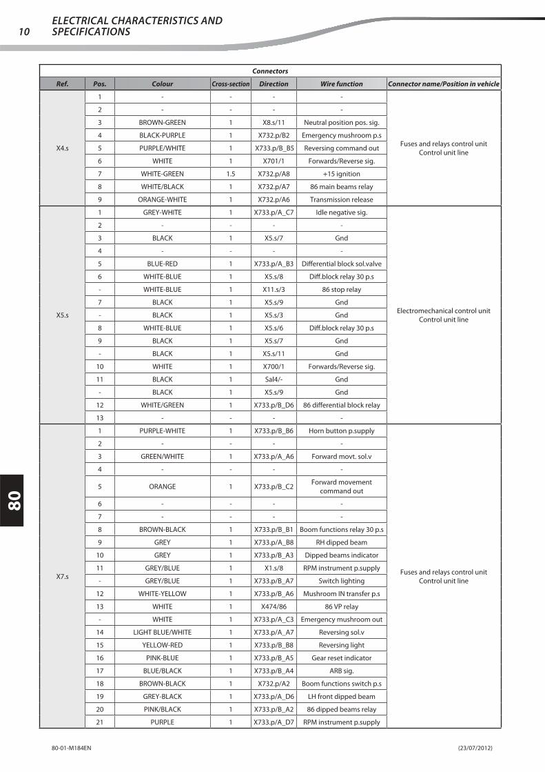
Connectors
Ref. Pos. Colour Cross-section Direction Wire function Connector name/Position in vehicle
X4.s
1 - - - -
Fuses and relays control unit
Control unit line
2 - - - -
3 BROWN-GREEN 1 X8.s/11 Neutral position pos. sig.
4 BLACK-PURPLE 1 X732.p/B2 Emergency mushroom p.s
5 PURPLE/WHITE 1 X733.p/B_B5 Reversing command out
6 WHITE 1 X701/1 Forwards/Reverse sig.
7 WHITE-GREEN 1.5 X732.p/A8 +15 ignition
8 WHITE/BLACK 1 X732.p/A7 86 main beams relay
9 ORANGE-WHITE 1 X732.p/A6 Transmission release
X5.s
1 GREY-WHITE 1 X733.p/A_C7 Idle negative sig.
Electromechanical control unit
Control unit line
2 - - - -
3 BLACK 1 X5.s/7 Gnd
4 - - - -
5 BLUE-RED 1 X733.p/A_B3 Diff erential block sol.valve
6 WHITE-BLUE 1 X5.s/8 Diff .block relay 30 p.s
- WHITE-BLUE 1 X11.s/3 86 stop relay
7 BLACK 1 X5.s/9 Gnd
- BLACK 1 X5.s/3 Gnd
8 WHITE-BLUE 1 X5.s/6 Diff .block relay 30 p.s
9 BLACK 1 X5.s/7 Gnd
- BLACK 1 X5.s/11 Gnd
10 WHITE 1 X700/1 Forwards/Reverse sig.
11 BLACK 1 Sal4/- Gnd
- BLACK 1 X5.s/9 Gnd
12 WHITE/GREEN 1 X733.p/B_D6 86 diff erential block relay
13 - - - -
X7.s
1 PURPLE-WHITE 1 X733.p/B_B6 Horn button p.supply
Fuses and relays control unit
Control unit line
2 - - - -
3 GREEN/WHITE 1 X733.p/A_A6 Forward movt. sol.v
4 - - - -
5 ORANGE 1 X733.p/B_C2Forward movement
command out
6 - - - -
7 - - - -
8 BROWN-BLACK 1 X733.p/B_B1 Boom functions relay 30 p.s
9 GREY 1 X733.p/A_B8 RH dipped beam
10 GREY 1 X733.p/B_A3 Dipped beams indicator
11 GREY/BLUE 1 X1.s/8 RPM instrument p.supply
- GREY/BLUE 1 X733.p/B_A7 Switch lighting
12 WHITE-YELLOW 1 X733.p/B_A6 Mushroom IN transfer p.s
13 WHITE 1 X474/86 86 VP relay
- WHITE 1 X733.p/A_C3 Emergency mushroom out
14 LIGHT BLUE/WHITE 1 X733.p/A_A7 Reversing sol.v
15 YELLOW-RED 1 X733.p/B_B8 Reversing light
16 PINK-BLUE 1 X733.p/B_A5 Gear reset indicator
17 BLUE/BLACK 1 X733.p/B_A4 ARB sig.
18 BROWN-BLACK 1 X732.p/A2 Boom functions switch p.s
19 GREY-BLACK 1 X733.p/A_D6 LH front dipped beam
20 PINK/BLACK 1 X733.p/B_A2 86 dipped beams relay
21 PURPLE 1 X733.p/A_D7 RPM instrument p.supply

(23/07/2012) 80-01-M184EN
80
11ELECTRICAL CHARACTERISTICS AND
SPECIFICATIONS
Connectors
Ref. Pos. Colour Cross-section Direction Wire function Connector name/Position in vehicle
X8.s
1 GREY/BLUE 1 X733.p/A_D4 Enable start up
Fuses and relays control unit
Control unit line
2 LIGHT BLUE-YELLOW 1 X733.p/B_D5 +50 start
- LIGHT BLUE-YELLOW 1 X733.p/A_C6 Start-up command
3 - - - -
4 - - - -
5 GREY-RED 1 X733.p/B_D3 Steering selector p.supply
6 LIGHT BLUE-BLACK 1 X733.p/B_D2 High speed indicator
7 ORANGE/WHITE 1 X733.p/A_C1 Speed change command
8 BROWN-WHITE 1 X733.p/B_C8 Low speed indicator
9 LIGHT BLUE/YELLOW 1 X733.p/B_C7 Intermittence charge
10 GREY-BLUE 1.5 X733.p/A_A8 Warning siren
11 BROWN-GREEN 1 X4.s/3 Neutral position pos. sig.
- BROWN-GREEN 1 X733.p/B_C6 Neutral position
12 PINK-WHITE 1 X733.p/A_B6 1200 rpm sol.v
13 - - - -
14 BLACK 1 Sal4/- Gnd
15 LIGHT BLUE-YELLOW 1 X733.p/A_B5 85 1200 rpm sol.v relay
16 BLUE/WHITE 1 X733.p/B_C5 Direction lights indicator
17 ORANGE-RED 1 X733.p/B_C4 Intermittence p.s
X10.s 1 GREEN 4 X731.p/11 +15 heating+15 heating
Control unit line
X11.s
1 LIGHT BLUE/WHITE 1 X733.p/B_C3 86 speed change relay
Fuses and relays control unit
Control unit line
2 RED-GREEN 1 X733.p/A_D3 85 Stop lights relay
3 WHITE-BLUE 1 X11.s/6 Jumper
- WHITE-BLUE 1 X5.s/6 86 stop relay
4 - - - -
5 GREY-BLACK 1.5 X733.p/B_D1Mix. bucket switch and
double/triple out. p.s
6 WHITE-BLUE 1 X11.s/3 Jumper
7 RED-YELLOW 1 X733.p/B_C1 Brake pedal sig.
X100
1 WHITE-YELLOW 0.5 X112/1 - Mix. Temp.
Air conditioning panel connector
Air conditioning kit
2 PURPLE-BLACK 0.5 X112/2 Mix. Temp.
3 GREY 0.5 X10²/B3 1° Speed
4 PURPLE 0.5 X10³/85 3° Speed
5 PINK 0.5 X111/1 + MIX
6 RED-BLACK 0.5 SA2/- + Key
7 BLACK 0.5 SA3-5/- Ground
8 RED 0.5 SA4/- + Battery
9 WHITE 1 X10⁸/2 - Ext Temp
10 PINK-BLACK 1 X10⁸/1 Ext Temp
11 BROWN 0.5 X10²/B5 2° Speed
12 - - - -
13 LIGHT BLUE-WHITE 0.5 X111/2 - MIX
14 BROWN-WHITE 0.5 X10⁵/1 Recirculation
15 GREEN 0.5 SA1/- Compressor
16 RED-BLACK 0.5 SA2/- + Lights
X101
1 GREEN/WHITE 1 X160.s/5 Forward movt. sol.vForward movement solenoid valve
Front line2 BLACK 1 Gnd1.1/- Gnd
T - - - -

(23/07/2012)80-01-M184EN
80
12ELECTRICAL CHARACTERISTICS AND SPECIFICATIONS
Connectors
Ref. Pos. Colour Cross-section Direction Wire function Connector name/Position in vehicle
X102
1 LIGHT BLUE/WHITE 1 X160.s/6 Reversing sol.vReversing sol.valve
Front line2 BLACK 1 Gnd1.1/- Gnd
T - - - -
X102
A1 GREEN 1.5 X10⁶/1 -
Relay control unit
Air conditioning kit
A2 RED-BLACK 1.5 SA2/- -
A3 - - - -
A4 RED 0.5 SA4/- -
A5 GREEN 0.5 SA1/- Compressor
A6 GREEN-WHITE 0.5 X104.3/1 -
A7 RED-BLACK 0.5 SA2/- -
A8 BROWN 1.5 X110/2 -
B1 - - - -
B2 - - - -
B3 GREY 0.5 X100/3 1° Speed
B4 RED-BLACK 0.5 SA2/- -
B5 BROWN 0.5 X100/11 2° Speed
B6 RED 0.5 SA4/- -
B7 - - - -
B8 - - - -
C1 RED 2.5 SA4/- -
C2 YELLOW 1.5 X110/3 -
C3 BLUE 1.5 X104.1/1 -
C4 BLUE-BLACK 1.5 X104.2/1 -
C5 RED 1.5 SA4/- -
C6 - - - -
C7 - - - -
C8 RED-BLACK 1.5 SA2/- -
X103
85 PURPLE 0.5 X100/4 3a Speed
Third speed relay
Air conditioning kit
86 RED-BLACK 0.5 SA2/- +12V
30 RED-BLACK 2.5 SA2/- +12V
87 ORANGE 2.5 X10⁹/B 3rd speed
87a - - - -
X103
1 PINK-WHITE 1 X160.s/7 1200 rpm sol.v1200rpm sol.valve
Front line2 BLACK 1 Gnd1.1/- Gnd
T - - - -
X104.11 BLUE 1.5 X10²/C3 - Air conditioner fan
Air conditioning kit2 BLACK 1.5 SA3-5/- Ground
X104.21 BLUE-BLACK 1.5 X10²/C4 - Air conditioner fan
Air conditioning kit2 BLACK 1.5 SA3-5/- Ground
X104.31 GREEN-WHITE 0.5 X10²/A6 - Air conditioning pressure switch
Air conditioning kit2 LIGHT BLUE 0.5 X110/1 -
X105
1 BROWN-WHITE 0.5 X100/14 RecirculationRecirculation connector
Air conditioning kit2 BLACK 0.5 SA3-5/- Ground
3 RED-BLACK 0.5 SA2/- +12V
X1051 LIGHT BLUE-GREEN 1.5 X720.s/U Fuel oil fi lter heater Fuel oil fi lter heater
Motor line2 BLACK 1.5 Gnd2/- Gnd
X106 1 GREEN 1.5 X10²/A1 -Compressor
Air conditioning kit

(23/07/2012) 80-01-M184EN
80
13ELECTRICAL CHARACTERISTICS AND
SPECIFICATIONS
Connectors
Ref. Pos. Colour Cross-section Direction Wire function Connector name/Position in vehicle
X107
1 RED 2.5 SA4/- -
Driver's seat connector
Air conditioning kit
2 BLACK 2.5 SA3-5/- Ground
3 - - - -
4 - - - -
X1081 PINK-BLACK 1 X100/10 Ext Temp External temperature thermostat
Air conditioning kit2 WHITE 1 X100/9 - Ext Temp
X109A BLACK 2.5 SA3-5/- Ground Third speed
Air conditioning kitB ORANGE 2.5 X10³/87 3rd speed
X109.1 1 WHITE-RED 1 X160.s/11Gear engaged microswitch
p.s
Gear engaged micro
Front line
X109.2 1 YELLOW-GREEN 1 X160.s/12Gear engaged microswitch
sig.
Gear engaged micro
Front line
X110
1 LIGHT BLUE 0.5 X104.3/2 -
First - Second speed
Air conditioning kit
2 BROWN 1.5 X10²/A8 -
3 YELLOW 1.5 X10²/C2 -
4 GREEN 0.5 SA1/- Compressor
X110
1 LIGHT BLUE-BLACK 1 X160.s/13 High speed sol.vHigh speed solenoid valve
Front line2 BLACK 1 Gnd1.1/- Gnd
T - - - -
X1111 PINK 0.5 X100/5 + MIX Cock command
Air conditioning kit2 LIGHT BLUE-WHITE 0.5 X100/13 - MIX
X111
1 BROWN-WHITE 1 X160.s/14 Low speed sol.vLow speed solenoid valve
Front line2 BLACK 1 Gnd1.1/- Gnd
T - - - -
X1121 WHITE-YELLOW 0.5 X100/1 - Mix. Temp. Mixer temperature cock
Air conditioning kit2 PURPLE-BLACK 0.5 X100/2 Mix. Temp.
X112.p1 - - - - X112 Counterfi gure
Front line2 - - - -
X112.s1 BLUE-RED 1 X160.s/10 Diff erential block sol.valve Diff erential block solenoid valve
Front line2 BLACK 1 Gnd1.1/- Gnd
X113
1 BLACK 1.5 Gnd1.1/- Gnd
RH front head light
Front line
2 GREY 1.5 X160.s/22 RH dipped beam
3 GREEN 1.5 X160.s/24 RH main beam
4 YELLOW-BLACK 1 Sal2/- RH front position lights
5 LIGHT BLUE 1 X160.s/23 RH direction light
6 - - - -
X114
1 GREY-WHITE 1 X160.s/19 RH levelling sol.vRH levelling sol.valve
Front line2 BLACK 1 Gnd1.2/- Gnd
T - - - -
X115
1 GREY-YELLOW 1 X160.s/2 LH levelling sol.vLH levelling solenoid valve
Front line2 BLACK 1 Gnd1.2/- Gnd
T - - - -
X116
1 ORANGE/BLACK 1 X160.s/20 Crab steering sol.vCrab steering solenoid valve
Front line2 BLACK 1 Gnd1.2/- Gnd
T - - - -
X117
1 BROWN/WHITE 1 X160.s/17 Four-wheel steering sol.vFour-wheel steering sol.valve
Front line2 BLACK 1 Gnd1.2/- Gnd
T - - - -

(23/07/2012)80-01-M184EN
80
14ELECTRICAL CHARACTERISTICS AND SPECIFICATIONS
Connectors
Ref. Pos. Colour Cross-section Direction Wire function Connector name/Position in vehicle
X118
1 PINK-YELLOW 1 Sal1/-Front axle alignment sensor
p.supplyFront axle alignment sensor
Front line2 BLACK 1 X147.2/1 Gnd
3 LIGHT BLUE-WHITE 1 X160.s/8 Front axle alignment signal
X119.1 1 GREY-BLUE 1.5 X733.s/A_A8 Warning sirenWarning siren
Driver's seat line
X119.2 1 BLACK 1.5 Gnd4.1/- GndWarning siren
Driver's seat line
X120
1 GREY-BLACK 1 X160.s/16 Fuel reserve indicatorFuel tank fl oat
Front line2 ORANGE 1 X160.s/18 Fuel level sig.
3 BLACK 1 Gnd1.1/- Gnd
X124
1 PINK-YELLOW 1 X128.s/10 Axle sensors p.supplyRear axle alignment sensor
Rear line2 BLACK 1 Gnd2/- Gnd
3 YELLOW-BROWN 1 X128.s/11 Rear axle alignment signal
X1251 YELLOW/BLACK 1 X128.s/2 Optional 2 sol.v Optional 2 solenoid valve
Rear line2 BLACK 1 Gnd2/- Gnd
X1261 LIGHT BLUE/YELLOW 1 X128.s/1 Optional 1 sol.v Optional 1 solenoid valve
Rear line2 BLACK 1 Gnd2/- Gnd
X1271 GREY/RED 1 X128.s/3 Retract sol.v Retract solenoid valve
Rear line2 BLACK 1 Gnd2/- Gnd

(23/07/2012) 80-01-M184EN
80
15ELECTRICAL CHARACTERISTICS AND
SPECIFICATIONS
Connectors
Ref. Pos. Colour Cross-section Direction Wire function Connector name/Position in vehicle
X128.p
1 LIGHT BLUE/YELLOW 1 X825.2/R6 Optional 1 sol.v
Rear chassis line connection
connector
Driver's seat line
2 YELLOW/BLACK 1 X825.2/R8 Optional 2 sol.v
3 GREY/RED 1 X825.2/R7 Retract sol.v
4 LIGHT BLUE 1 X185.s/5 RH direction light
5 - - - -
6 BLACK-PURPLE 1 X825.2/L28NO boom closed
microswitch sig.
7 - - - -
8 BROWN/BLACK 1 X825.2/L30NC boom closed microswitch
sig.
9 BLUE-WHITE 1 X825.2/R9 Extension sol.v
10 PINK-YELLOW 1 Sal36/- Rear axle sensor p.supply
11 YELLOW-BROWN 1 X185.s/12 Rear axle alignment indicator
12 YELLOW-RED 1 X733.s/B_B8 Reversing light
13 WHITE/RED 1 X185.s/2 Rear fog lamp
14 RED-YELLOW 1 Sal101/- Brake pedal sig.
15 BROWN-BLACK 1 X208/5 Boom micro p.supply
16 YELLOW-BLACK 1 Sal37/- LH rear position light
17 YELLOW 1 Sal29/- RH rear position light
18 BLUE 1 X185.s/14 LH direction light
19 RED-BLACK 1 X825.2/R18 VCI sol.valve
20 - - - -
21 - - - -
22 - - - -
23 - - - -
24 GREY-GREEN 1 Sal46/- ARB cell p.supply
25 PURPLE 1 Sal44/- CAN shield
26 YELLOW 0.5 Sal45/- Can H (Open)
27 BLACK 0.5 Sal42/- Can L (Open)
28 BLUE-BLACK 1 Sal47/- ARB cell Gnd
29 GREY-GREEN 1 Sal46/- Boom angle sensor p.supply
30 BLUE-BLACK 1 Sal47/- Boom angle sensor Gnd
31 GREY 1 X825.2/L32 Boom 1 angle sig.
32 GREEN X825.2/L34 Boom 2 angle sig.
33 LIGHT BLUE/WHITE 1 X825.2/R4 VRD sol.v
34 PURPLE/BLACK 1 X825.2/R15 VS sol.v
35 - - - -
36 - - - -
37 - - - -
38 - - - -
39 - - - -
40 - - - -
41 - - - -
42 - - - -
43 - - - -
44 - - - -
45 - - - -
46 - - - -
47 - - - -

(23/07/2012)80-01-M184EN
80
16ELECTRICAL CHARACTERISTICS AND SPECIFICATIONS
Connectors
Ref. Pos. Colour Cross-section Direction Wire function Connector name/Position in vehicle
X128.s
1 LIGHT BLUE/YELLOW 1 X126/1 Optional 1 sol.v
Driver's seat line conection
connector
Rear line
2 YELLOW/BLACK 1 X125/1 Optional 2 sol.v
3 GREY/RED 1 X127/1 Retract sol.v
4 LIGHT BLUE 1 Sal18/- RH direction light
5 - - - -
6 BLACK-PURPLE 1 X140/3Boom retracted microswitch
NO
7 - - - -
8 BROWN/BLACK 1 X139/4Boom retracted microswitch
NC
9 BLUE-WHITE 1 X142/1 Extension sol.v
10 PINK-YELLOW 1 X124/1 Axle sensor p.supply
11 YELLOW-BROWN 1 X124/3 Rear axle alignment signal
12 YELLOW-RED 1 Sal12/- Reversing light
13 WHITE/RED 1 Sal13/- Rear fog lamp
14 RED-YELLOW 1 Sal14/- Stop lights
15 BROWN-BLACK 1 Sal15/- Boom micro p.supply
16 YELLOW-BLACK 1 Sal21/- LH rear position light
17 YELLOW 1 Sal17/- RH rear position light
18 BLUE 1 Sal20/- LH rear direction light
19 RED-BLACK 1 X955/1 VCI sol.valve
20 - - - -
21 - - - -
22 - - - -
23 - - - -
24 RED 0.32 X851/2 ARB cell p.supply
25 PURPLE 1 Sal23/- SCH
26 WHITE 0.2 X851/4 Can H Open
27 BLUE 0.2 X851/5 Can L Open
28 BLACK 0.32 X851/3 ARB cell Gnd
29 GREY-GREEN 1 Sal24/- Boom angle sensor p.supply
30 BLUE-BLACK 1 Sal25/- Boom sensor Gnd
31 GREY 1 X952/3 Boom 1 angle sig.
32 GREEN 1 X952/6 Boom 2 angle sig.
33 A/WHITE 1 X611/1 VRD sol.v (Slow-Motion)
34 PURPLE/BLACK 1 X633/1 VS sol.v (slewing)
35 - - - -
36 - - - -
37 - - - -
38 - - - -
39 - - - -
40 - - - -
41 - - - -
42 - - - -
43 - - - -
44 - - - -
45 - - - -
46 - - - -
47 - - - -

(23/07/2012) 80-01-M184EN
80
17ELECTRICAL CHARACTERISTICS AND
SPECIFICATIONS
Connectors
Ref. Pos. Colour Cross-section Direction Wire function Connector name/Position in vehicle
X131.p1 - - - - Cap
Rear line2 - - - -
X131.s1 YELLOW-BLACK 1 Sal21/- License plate light License plate light
Rear line2 BLACK 1 Gnd3/- Gnd
X1321 YELLOW-RED 1 Sal12/- Reversing buzzer Buzzer
Rear line2 BLACK 1 Gnd3/- Gnd
X138
1 BLACK 1 Gnd3/- Gnd
LH rear light
Rear line
2 YELLOW-BLACK 1 Sal21/- LH rear position light
3 YELLOW-RED 1 Sal12/- LH reversing light
4 BLUE 1 Sal20/- LH direction light
5 RED-YELLOW 1 Sal14/- LH stop light
6 WHITE/RED 1 Sal13/- LH rear fog lamp
7 - - - -
X139
1 - - - -
Boom retracted microswitch NC
Rear line
2 BROWN-BLACK 1 Sal15/-Boom retracted micro
p.supply
3 - - - -
4 BROWN/BLACK 1 X128.s/8Boom retracted microswitch
NC
X140
1 BROWN-BLACK 1 Sal15/- Boom micro p.supply
Boom retracted microswitch NO
Rear line
2 - - - -
3 BLACK-PURPLE 1 X128.s/6Boom retracted microswitch
NO
4 - - - -
X141
1 BLACK 1 Gnd3/- Gnd
RH rear light
Rear line
2 YELLOW 1 Sal17/- RH rear position light
3 YELLOW-RED 1 Sal12/- RH reversing light
4 LIGHT BLUE 1 Sal18/- RH direction light
5 RED-YELLOW 1 Sal14/- RH stop light
6 WHITE/RED 1 Sal13/- RH rear fog lamp
7 - - - -
X1421 BLUE-WHITE 1 X128.s/9 Extension sol.v Extension solenoid valve
Rear line2 BLACK 1 Gnd2/- Gnd
X146
1 WHITE-YELLOW 1 X160.s/15 Parking brake solenoid valveParking brake solenoid valve
Front line2 BLACK 1 Gnd1.2/- Gnd
T - - - -
X147.1 1 GREEN-BLACK 1 X160.s/9 Parking brake indicatorParking brake pressure switch
Front line
X147.21 BLACK 1 Gnd1.2/- Gnd Parking brake pressure switch
Front line- BLACK 1 X118/2 Gnd

(23/07/2012)80-01-M184EN
80
18ELECTRICAL CHARACTERISTICS AND SPECIFICATIONS
Connectors
Ref. Pos. Colour Cross-section Direction Wire function Connector name/Position in vehicle
X160.p
1 WHITE/GREEN 1 X186.s/3 Diff . block indicator
Front carriage line connection
connector
Driver's seat line
2 GREY-YELLOW 1 X825.2/R20 LH levelling sol.v
3 - - - -
4 PINK-YELLOW 1 Sal36/- Axles sensors p.s
5 GREEN/WHITE 1 X733.s/A_A6 Forward movt. sol.v
6 LIGHT BLUE/WHITE 1 X733.s/A_A7 Reversing sol.v
7 PINK-WHITE 1 X733.s/A_B6 1200 rpm sol.v
8 LIGHT BLUE-WHITE 1 X185.s/8 Front axle alignment signal
9 GREEN-BLACK 1 X464/16 Parking brake sig.
10 BLUE-RED 1 X206.s/6 Diff erential block sol.valve
11 WHITE-YELLOW 1 X206.s/20Gear engaged microswitch
p.s
12 YELLOW-GREEN 1 X825.2/L31Gear engaged microswitch
sig.
13 LIGHT BLUE-BLACK 1 X186.s/18 2nd speed sol.v
14 BROWN-WHITE 1 X186.s/17 1st speed sol.v
15 WHITE-YELLOW 1 X825.2/R14 Parking brake solenoid valve
16 GREY-BLACK 1 X206.s/11 Fuel reserve indicator
17 BROWN/WHITE 1 X185.s/3 Four-wheel steering sol.v
18 ORANGE 1 X206.s/5 Fuel level sig.
19 GREY-WHITE 1 X825.2/R19 RH levelling sol.v
20 ORANGE/BLACK 1 X185.s/4 Crab steering sol.v
21 - - - -
22 GREY 1 X733.s/A_B8 RH dipped beam
23 LIGHT BLUE 1 X191/8 RH direction light
24 GREEN 1 X733.s/A_B1 RH main beam
25 YELLOW-BLACK 1 Sal37/- Position light
26 - - - -
27 - - - -
28 - - - -
29 - - - -
30 - - - -
31 - - - -
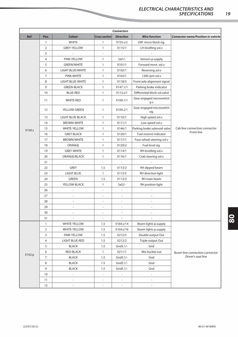
(23/07/2012) 80-01-M184EN
80
19ELECTRICAL CHARACTERISTICS AND
SPECIFICATIONS
Connectors
Ref. Pos. Colour Cross-section Direction Wire function Connector name/Position in vehicle
X160.s
1 WHITE 1 X755.s/2 Diff . micro block sig.
Cab line connection connector
Front line
2 GREY-YELLOW 1 X115/1 LH levelling sol.v
3 - - - -
4 PINK-YELLOW 1 Sal1/- Sensors p.supply
5 GREEN/WHITE 1 X101/1 Forward movt. sol.v
6 LIGHT BLUE/WHITE 1 X10²/1 Reversing sol.v
7 PINK-WHITE 1 X10³/1 1200 rpm sol.v
8 LIGHT BLUE-WHITE 1 X118/3 Front axle alignment signal
9 GREEN-BLACK 1 X147.1/1 Parking brake indicator
10 BLUE-RED 1 X112.s/1 Diff erential block sol.valve
11 WHITE-RED 1 X109.1/1Gear engaged microswitch
p.s
12 YELLOW-GREEN 1 X109.2/1Gear engaged microswitch
sig.
13 LIGHT BLUE-BLACK 1 X110/1 High speed sol.v
14 BROWN-WHITE 1 X111/1 Low speed sol.v
15 WHITE-YELLOW 1 X146/1 Parking brake solenoid valve
16 GREY-BLACK 1 X120/1 Fuel reserve indicator
17 BROWN/WHITE 1 X117/1 Four-wheel steering sol.v
18 ORANGE 1 X120/2 Fuel level sig.
19 GREY-WHITE 1 X114/1 RH levelling sol.v
20 ORANGE/BLACK 1 X116/1 Crab steering sol.v
21 - - - -
22 GREY 1.5 X113/2 RH dipped beam
23 LIGHT BLUE 1 X113/5 RH direction light
24 GREEN 1.5 X113/3 RH main beam
25 YELLOW-BLACK 1 Sal2/- RH position light
26 - - - -
27 - - - -
28 - - - -
29 - - - -
30 - - - -
31 - - - -
X162.p
1 WHITE-YELLOW 1.5 X164.s/14 Boom lights p.supply
Boom line connection connector
Driver's seat line
2 WHITE-YELLOW 1.5 X164.s/16 Boom lights p.supply
3 PINK-YELLOW 1.5 X212/5 Double output Out
4 LIGHT BLUE-RED 1.5 X212/2 Triple output Out
5 BLACK 1.5 Gnd5.1/- Gnd
6 RED-BLACK 1 X211/1 Mix bucket out
7 BLACK 1.5 Gnd5.1/- Gnd
8 BLACK 1.5 Gnd5.1/- Gnd
9 BLACK 1.5 Gnd5.1/- Gnd
10 - - - -
11 - - - -
12 - - - -

(23/07/2012)80-01-M184EN
80
20ELECTRICAL CHARACTERISTICS AND SPECIFICATIONS
Connectors
Ref. Pos. Colour Cross-section Direction Wire function Connector name/Position in vehicle
X162.s
1 - - - -
Capped counter-fi gure
Driver's seat line
2 - - - -
3 - - - -
4 - - - -
5 - - - -
6 - - - -
7 - - - -
8 - - - -
9 - - - -
10 - - - -
11 - - - -
12 - - - -
X163.p
1 - - - -
Capped counter-fi gure
Driver's seat line
2 - - -
3 - - - -
4 - - - -
X163.s
1 RED 2.5 X720.p/D +30 optional p.s
Optionals power supply connector
Driver's seat line
2 BLACK 2.5 Gnd4.4/- Gnd
3 PINK-BLACK 2.5 X731.s/8 +15 optional p.s
4 BLACK 2.5 Gnd4.4/- Gnd
X164.s
1 - - - -
Cab roof line connection connector
Driver's seat line
2 - - - -
3 LIGHT BLUE-YELLOW 1.5 X733.s/B_A1Roof and sides wiper switch
p.s
4 BLACK 1.5 Gnd4.2/- Gnd
5 WHITE-BLACK 1.5 X732.s/D8 Front work lights switch p.s
6 LIGHT BLUE/WHITE 1 X732.s/B7 Rotating beacon switch p.s.
7 RED-GREEN 1.5 X733.s/B_A8Rear work lights switch
p.supply
8 PINK/BLACK 1 X193/1 Rear wipers return
9 RED/BLACK 1 X192/2 Rear wiper command
10 RED 1 X178.1/1 +30 ceiling light
11 BLUE-YELLOW 1 X733.s/A_C8 Rear demister p.supply
12 BLACK 1.5 Gnd4.2/- Gnd
13 BLACK 1.5 Gnd4.2/- Gnd
14 WHITE-YELLOW 1.5 X162.p/1 Boom lights p.supply
15 BROWN-WHITE 1.5 X733.s/B_D8 Boom work lights switch p.s
16 WHITE-YELLOW 1.5 X162.p/2 Boom lights p.supply
17 - - - -
X165.s
1 BLACK 0.5 X200/8 - LH post. loudspeaker
Cab roof line connection connector
Driver's seat line
2 BROWN 0.75 X200/2 - RH post. loudspeaker
3 RED 0.5 X200/7 + LH post. loudspeaker
4 RED 0.75 X200/1 + RH post. loudspeaker
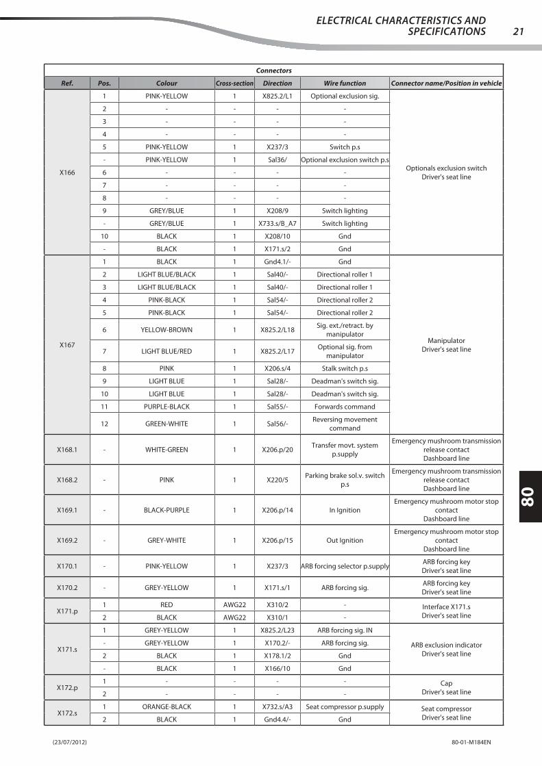
(23/07/2012) 80-01-M184EN
80
21ELECTRICAL CHARACTERISTICS AND
SPECIFICATIONS
Connectors
Ref. Pos. Colour Cross-section Direction Wire function Connector name/Position in vehicle
X166
1 PINK-YELLOW 1 X825.2/L1 Optional exclusion sig.
Optionals exclusion switch
Driver's seat line
2 - - - -
3 - - - -
4 - - - -
5 PINK-YELLOW 1 X237/3 Switch p.s
- PINK-YELLOW 1 Sal36/ Optional exclusion switch p.s
6 - - - -
7 - - - -
8 - - - -
9 GREY/BLUE 1 X208/9 Switch lighting
- GREY/BLUE 1 X733.s/B_A7 Switch lighting
10 BLACK 1 X208/10 Gnd
- BLACK 1 X171.s/2 Gnd
X167
1 BLACK 1 Gnd4.1/- Gnd
Manipulator
Driver's seat line
2 LIGHT BLUE/BLACK 1 Sal40/- Directional roller 1
3 LIGHT BLUE/BLACK 1 Sal40/- Directional roller 1
4 PINK-BLACK 1 Sal54/- Directional roller 2
5 PINK-BLACK 1 Sal54/- Directional roller 2
6 YELLOW-BROWN 1 X825.2/L18Sig. ext./retract. by
manipulator
7 LIGHT BLUE/RED 1 X825.2/L17Optional sig. from
manipulator
8 PINK 1 X206.s/4 Stalk switch p.s
9 LIGHT BLUE 1 Sal28/- Deadman's switch sig.
10 LIGHT BLUE 1 Sal28/- Deadman's switch sig.
11 PURPLE-BLACK 1 Sal55/- Forwards command
12 GREEN-WHITE 1 Sal56/-Reversing movement
command
X168.1 - WHITE-GREEN 1 X206.p/20Transfer movt. system
p.supply
Emergency mushroom transmission
release contact
Dashboard line
X168.2 - PINK 1 X220/5Parking brake sol.v. switch
p.s
Emergency mushroom transmission
release contact
Dashboard line
X169.1 - BLACK-PURPLE 1 X206.p/14 In Ignition
Emergency mushroom motor stop
contact
Dashboard line
X169.2 - GREY-WHITE 1 X206.p/15 Out Ignition
Emergency mushroom motor stop
contact
Dashboard line
X170.1 - PINK-YELLOW 1 X237/3 ARB forcing selector p.supplyARB forcing key
Driver's seat line
X170.2 - GREY-YELLOW 1 X171.s/1 ARB forcing sig.ARB forcing key
Driver's seat line
X171.p1 RED AWG22 X310/2 - Interface X171.s
Driver's seat line2 BLACK AWG22 X310/1 -
X171.s
1 GREY-YELLOW 1 X825.2/L23 ARB forcing sig. IN
ARB exclusion indicator
Driver's seat line
- GREY-YELLOW 1 X170.2/- ARB forcing sig.
2 BLACK 1 X178.1/2 Gnd
- BLACK 1 X166/10 Gnd
X172.p1 - - - - Cap
Driver's seat line2 - - - -
X172.s1 ORANGE-BLACK 1 X732.s/A3 Seat compressor p.supply Seat compressor
Driver's seat line2 BLACK 1 Gnd4.4/- Gnd

(23/07/2012)80-01-M184EN
80
22ELECTRICAL CHARACTERISTICS AND SPECIFICATIONS
Connectors
Ref. Pos. Colour Cross-section Direction Wire function Connector name/Position in vehicle
X173.1 1 GREY/BLUE RENU 1 X732.s/C4 Seat micro p.supplySeat microswitch
Driver's seat line
X173.2 1 YELLOW-GREEN 1 X825.2/L3 Seat microswitch sig.Seat microswitch
Driver's seat line
X174
A BLACK 2.5 Gnd5.2/- Gnd
Heating unit
Driver's seat line
B - - - -
C - - - -
D YELLOW 2.5 X177/1 3rd speed
E ORANGE-WHITE 1.5 X175/3 2nd speed
F LIGHT BLUE 1.5 X175/1 1st speed
X175
1 LIGHT BLUE 1.5 X174/F 1st speed
Heating panel
Driver's seat line
2 - - - -
3 ORANGE-WHITE 1.5 X174/E 2nd speed
4 GREEN 1.5 Sal21/- +15 heating panel
5 BLACK 1.5 Gnd4.4/- Gnd
X176 1 RED-BLACK 2.5 SA2/- + 12V+12V
Air conditioning kit
X176 1 GREEN 2.5 Sal21/- Front fan p.supplyHeating panel
Driver's seat line
X177 1 YELLOW 2.5 X174/D 3rd speedHeating panel
Driver's seat line
X178.1
1 RED 1.5 X733.s/A_D1 +30 socket
Cigarette lighter socket
Driver's seat line
- RED 1 X164.s/10 +30 ceiling light
2 BLACK 1.5 Gnd4.3/- Gnd
- BLACK 1 X171.s/2 Gnd
X178.2 1 YELLOW-BLACK 1 X732.s/C2 BacklightingCigarette lighter socket lighting
Driver's seat line

(23/07/2012) 80-01-M184EN
80
23ELECTRICAL CHARACTERISTICS AND
SPECIFICATIONS
Connectors
Ref. Pos. Colour Cross-section Direction Wire function Connector name/Position in vehicle
X185.p
1 - - - -
Cab line connection connector
Dashboard line
2 WHITE/RED 1 X221/1 Rear fog lamp
3 BROWN/WHITE 1 X222/1 Four-wheel steering sol.v
4 ORANGE/BLACK 1 X222/5 Crab steering sol.v
5 LIGHT BLUE 1 X235/1 RH indicator lights
6 - - - -
7 - - - -
8 LIGHT BLUE-WHITE 0.5 X501/3 Front axle indicator
9 BLUE/YELLOW 1 X220/7 Parking brake sig.
10 GREEN-BLACK 0.5 X501/22 Parking brake indicator
- GREEN-BLACK 1 X228/B2 Parking brake indicator
11 WHITE/GREEN 1 X213/3 86 diff erential block relay
12 YELLOW-BLUE 0.5 X501/2 Rear axle indicator
13 PINK-BLUE 1 X217/9 Gear reset indicator
14 BLUE 1 X235/3 LH indicator lights
15 PINK-BLACK 1 X484.s/1 D+ alternator
- PINK-BLACK 1 X228/A7 Battery indicator
16 GREY-YELLOW 1 X228/B1 Air fi lter clogged ind.
- GREY-YELLOW 0.5 X501/26 Air fi lter clogged ind.
17 YELLOW-BLUE 0.5 X501/28 Mercedes alarm indicator
18 WHITE-BLACK 0.5 X501/10 Mercedes alarm indicator
19 ORANGE-BLACK 0.5 X501/17 Preheating indicator
20 BROWN-BLACK 0.5 X228/A3 Water temp. max. indicator
- BROWN-BLACK 0.5 X501/5 Water temp. max. indicator
21 WHITE 0.5 X228/A8 Oil indicator
- WHITE 0.5 X501/21 Engine oil indicator

(23/07/2012)80-01-M184EN
80
24ELECTRICAL CHARACTERISTICS AND SPECIFICATIONS
Connectors
Ref. Pos. Colour Cross-section Direction Wire function Connector name/Position in vehicle
X185.s
1 PURPLE/WHITE 1 X466/3 Odometer sig.
Dashboard line connection
connector
Driver's seat line
2 WHITE/RED 1 X128.p/13 Rear fog lamp
3 BROWN/WHITE 1 X160.p/17 Four-wheel steering sol.v
4 ORANGE/BLACK 1 X160.p/20 Crab steering sol.v
5 LIGHT BLUE 1 X128.p/4 RH direction light
- LIGHT BLUE 1 X191/8 RH direction light
6 - - - -
7 PINK 0.5 X467/1 Engine oil level sig.
8 LIGHT BLUE-WHITE 1 X160.p/8 Front axle alignment signal
9 BLUE/YELLOW 1 X825.2/L2 Parking brake sig.
10 GREEN-BLACK 1 X825.2/R25 Parking brake applied sig.
- GREEN-BLACK 1 X464/16 Parking brake indicator light
11 WHITE/GREEN 1 X733.s/B_D6 86 diff erential block relay
12 YELLOW-BROWN 1 X128.p/11 Rear axle alignment indicator
13 PINK-BLUE 1 X733.s/B_A5 Gear reset indicator
14 BLUE 1 X191/9 LH direction light
- BLUE 1 X128.p/18 LH direction light
15 PINK-BLACK 1 X224.s/C D+ alternator
- PINK-BLACK 1 X733.s/B_D4 D+ alternator
16 GREY-YELLOW 0.5 X720.p/H Oil fi lter clogged indicator
17 YELLOW-BLUE 1 X464/5Engine general alarm
indicator
18 WHITE-BLACK 1 X761.s/2 Engine alert indicator
- WHITE-BLACK 1 X464/6 Engine alert indicator
19 ORANGE-BLACK 1 X464/7 Spark plugs
20 BROWN-BLACK 1 X466/12High water temperature
indicator
BROWN-BLACK 1 X825.2/R27High water temperature
indicator
21 WHITE 1 X465/3Engine oil pressure low
indicator
- WHITE 1 X825.2/R26 Engine oil pressure low sig.

(23/07/2012) 80-01-M184EN
80
25ELECTRICAL CHARACTERISTICS AND
SPECIFICATIONS
Connectors
Ref. Pos. Colour Cross-section Direction Wire function Connector name/Position in vehicle
X186.p
1 GREY-YELLOW 0.5 X501/13 Water temperature sig.
Cab line connection connector
Dashboard line
2 RED-YELLOW 1 X213/1 Brake pedal sig.
3 BLUE-RED 0.5 X501/8 Diff erential block indicator
4 WHITE-BLUE 1 X228/A5Brakes fl uid level indicator
light
- WHITE-BLUE 0.5 X501/23Brakes fl uid level low
indicator light
5 LIGHT BLUE/YELLOW 1 X235/5 Load
6 PINK-WHITE 0.5 X501/25 Steering fault indicator light
7 ORANGE-WHITE 1 X217/1 Speed reset command
8 WHITE-RED 1 X217/5 Reset switch p.s.
9 - - - -
10 - - - -
11 BLACK 1.5 Sal36/- Ground
12 ORANGE-BLUE 1 X221/5 Rear fog lamp switch p.s.
13 - - - -
14 - - - -
15 - - - -
16 ORANGE/WHITE 1 X216/1 Speed change
17 BROWN-WHITE 1 X214/9 Low speed
18 LIGHT BLUE-BLACK 1 X215/9 High speed
19 GREY-RED 1 X222/3 Steering switch p.s.
20 RED 1 X235/2 +30 Warning
21 ORANGE-RED 1 X235/4 Intermittence p.s
X186.s
1 GREY-YELLOW 1 X465/4 Water temp. instrument sig.
Dashboard line connection
connector
Driver's seat line
2 LIGHT BLUE/GREEN 1 X731.s/4 Stop lights
3 WHITE/GREEN 1 X160.p/1 Diff . block indicator
4 WHITE-BLUE 1 X198.1/1Brakes fl uid level low
indicator light
5 LIGHT BLUE/YELLOW 1 X191/7 Intermittence charge
LIGHT BLUE/YELLOW 1 X733.s/B_C7 Intermittence charge
6 PINK-WHITE 1 X825.2/R33 Steering low pressure sig.
- PINK-WHITE 1 X281.1/1Steering comp. low pressure
sig.
7 ORANGE-WHITE 1 X825.2/L29 Gear reset sig.
8 WHITE-RED 1 X732.s/D3 Reset switch p.s.
9 - - - -
10 - - - -
11 BLACK 1.5 Gnd4.3/- Gnd
12 ORANGE-BLUE 1 Sal19/- Rear fog lamp switch p.s.
13 - - - -
14 - - - -
15 - - - -
16 ORANGE/WHITE 1 X733.s/A_C1 Speed change command
17 BROWN-WHITE 1 X160.p/14 1st speed sol.v
- BROWN-WHITE 1 X733.s/B_C8 Low speed indicator
18 LIGHT BLUE-BLACK 1 X733.s/B_D2 High speed indicator
- LIGHT BLUE-BLACK 1 X160.p/13 2nd speed sol.v
19 GREY-RED 1 X733.s/B_D3 Steering selector p.supply
20 RED 1 X732.s/C8 +30 warning
21 ORANGE-RED 1 X733.s/B_C4 Intermittence p.s

(23/07/2012)80-01-M184EN
80
26ELECTRICAL CHARACTERISTICS AND SPECIFICATIONS
Connectors
Ref. Pos. Colour Cross-section Direction Wire function Connector name/Position in vehicle
X187.1
1 RED 6 X725.p/1 +30 start-up panel
Start-up panel
Driver's seat line
2 - - - -
3 - - - -
4 - - - -
X187.2
5 BLUE 6 X730.s/1 +15 key
Start-up panel
Driver's seat line
6 BLUE/WHITE 1 X732.s/B8 86 services relay
7 LIGHT BLUE-YELLOW 1 X733.s/B_D5 +50 start
8 - - - -
9 - - - -
10 - - - -
X188
1 BLACK 1.5 Gnd4.1/- Gnd
Front window-wiper
Driver's seat line
2 ORANGE-WHITE 1.5 X193/2 Front wiper return
3 PINK-BLACK 1.5 X192/3 Front w.wipers p.supply
- PINK-BLACK 1.5 X733.s/A_A1 Front w.wipers p.supply
4 BROWN-BLACK 1.5 X192/7 1st speed
5 - - - -
6 WHITE-BLACK 1.5 X192/8 2° wipers speed
X191
1 ORANGE-BLUE 1.5 Sal19/- Indicator stalk lights p.s
LH indicator stalk
Driver's seat line
2 GREY-RED 1.5 X732.s/D1Position lights from indicator
stalk
3 PINK/BLACK 1 X733.s/B_A2 86 dipped beams relay
4 WHITE/BLACK 1 X732.s/A7 86 main beams relay
5 PURPLE-WHITE 1 X733.s/B_B6 Horn button p.supply
6 LIGHT BLUE-WHITE 1 Sal100/- Horn
- LIGHT BLUE-WHITE 1 X733.s/B_D7 86 warning siren relay
7 LIGHT BLUE/YELLOW 1 X186.s/5 Intermittence charge
8 LIGHT BLUE 1 X160.p/23 RH direction light
- LIGHT BLUE 1 X185.s/5 RH direction light
9 BLUE 1 X185.s/14 LH direction light
- BLUE 1 X473/5 LH direction light
X192
1 BLUE-YELLOW 1 X192/5 Sprayer p.s
RH indicator stalk
Driver's seat line
- BLUE-YELLOW 1 X733.s/A_A3 Rear w.wipers indicator stalk p.s
2 RED/BLACK 1 X164.s/9 Rear wiper command
3 PINK-BLACK 1.5 X188/3 Front w.wipers p.supply
4 - - - -
5 BLUE-YELLOW 1 X192/1 Sprayer p.s
6 PURPLE 1 X196/1 Window wiper sprayer
7 BROWN-BLACK 1.5 X188/4 1st speed
8 WHITE-BLACK 1.5 X188/6 2° wipers speed
9 - - - -
X1931 PINK/BLACK 1 X164.s/8 Rear wipers return RH indicator stalk
Driver's seat line2 ORANGE-WHITE 1.5 X188/2 Front wiper return
X196
1 PURPLE 1 X192/6 Window wiper sprayerWindow wiper sprayer
Driver's seat line2 BLACK 1 Gnd4.1/- Gnd
- BLACK 1 X198.2/1 Gnd
X197.1 1 BROWN-GREEN 1 X733.s/B_C6 Neutral positionStop pedal pressure switch
Driver's seat line
X197.21 LIGHT BLUE/WHITE 1 X733.s/B_C3 86 speed change relay Stop pedal pressure switch
Driver's seat line- LIGHT BLUE/WHITE 1 X731.s/5 Stop pedal pressure switch
X198.1 1 WHITE-BLUE 1 X186.s/4Brakes fl uid level low
indicator light
Brakes fl uid level
Driver's seat line

(23/07/2012) 80-01-M184EN
80
27ELECTRICAL CHARACTERISTICS AND
SPECIFICATIONS
Connectors
Ref. Pos. Colour Cross-section Direction Wire function Connector name/Position in vehicle
X198.21 BLACK 1 X281.2/1 Gnd Brakes fl uid level
Driver's seat line- BLACK 1 X196/2 Gnd
X200
1 RED 0.75 X165.s/4 + RH post. loudspeaker
Car radio loudspeaker
Driver's seat line
2 BROWN 0.75 X165.s/2 - RH post. loudspeaker
3 - - - -
4 - - - -
5 - - - -
6 - - - -
7 RED 0.5 X165.s/3 + LH post. loudspeaker
8 BLACK 0.5 X165.s/1 - LH post. loudspeaker
X201
1 YELLOW 0.5 X464/14 Accelerator pedal 1 pin
Accelerator pedal
Driver's seat line
2 BROWN-WHITE 0.5 X464/12 Accelerator pedal 2 pin
3 YELLOW 0.5 X464/14 Accelerator pedal 3 pin
4 GREY-WHITE 0.5 X464/13 Accelerator pedal 4 pin
5 BLUE-BLACK 0.5 X466/5 Accelerator pedal 5 pin
6 BLUE-BLACK 0.5 X466/5 Accelerator pedal 6 pin
7 - - - -
8 - - - -
9 - - - -
X204.3 1 BLACK 2.5 SA3-5/- GroundGround
Air conditioning kit
X204.3 1 BLACK 2.5 Gnd4.3/- GndGnd
Driver's seat line
X206.p
1 BROWN-GREEN 1 X235/8 +15 Warning
Cab line connection connector
Dashboard line
2 GREY-RED 0.5 X501/15 RPM signal
3 GREY/BLUE 1 Sal35/- +15 p.s.
4 PINK 1 X220/5Transfer movt. system
p.supply
5 ORANGE 0.5 X501/20 Fuel level sig.
6 BLUE-RED 1 X213/2 Diff erential block sol.valve
7 BLUE-WHITE 0.5 X501/19 Direction lights indicator
8 YELLOW 0.5 X501/7 Position lights indicator
- YELLOW 1 X228/B4 Positions indicator
9 GREEN 1 X228/B8 Main beams indicator
10 - - - -
11 GREY-BROWN 0.5 X501/1 Fuel reserve indicator
12 PURPLE 0.5 X501/9 +15 ECO instrument
13 BLACK 1.5 Sal36/- Ground
14 BLACK-PURPLE 1 X169.1/- In Ignition
15 GREY-WHITE 1 X169.2/- Out Ignition
16 - - - -
17 - - - -
18 GREY-BLUE 0.5 X501/27 ARB forcing sig.
19 RED-BLACK 0.5 X501/14 Rexroth error indicator
20 WHITE-GREEN 1 X168.1/-Transfer movt. system
p.supply
21 - - - -

(23/07/2012)80-01-M184EN
80
28ELECTRICAL CHARACTERISTICS AND SPECIFICATIONS
Connectors
Ref. Pos. Colour Cross-section Direction Wire function Connector name/Position in vehicle
X206.s
1 BROWN-GREEN 1 X732.s/B4 +15 warning switch
Dashboard line connection
connector
Driver's seat line
2 GREY-RED 1 X465/6 W alternator
3 GREY/BLUE 1 Sal35/-Instruments and CAN control
unit p.s
4 PINK 1 X167/8 Stalk switch p.s
5 ORANGE 1 X160.p/18 Fuel level sig.
6 BLUE-RED 1 X733.s/A_B3 Diff erential block sol.valve
- BLUE-RED 1 X160.p/10 Diff erential block sol.valve
7 BLUE/WHITE 1 X733.s/B_C5 Direction lights indicator
8 YELLOW 1 Sal29/- Position lights indicator
9 GREEN 1 X732.s/D4 Main beams indicator
10 GREY 1 X733.s/B_A3 Dipped beams indicator
11 GREY-BLACK 1 X160.p/16 Fuel reserve indicator
12 PURPLE 1 X733.s/A_D7 RPM instrument p.supply
13 BLACK 1.5 Gnd4.2/- Gnd
14 BLACK-PURPLE 1 X732.s/B2 Emergency mushroom p.s
15 GREY-WHITE 1 X256.p/6Emergency mushroom out
(ignition)
16 - - - -
17 - - - -
18 GREY-BLUE 1 X825.1/9 ARB forcing sig.
19 RED-BLACK 1 X825.1/8 Over-revving indicator light
20 WHITE-YELLOW 1 X733.s/B_A6 Mushroom IN transfer p.s
- WHITE-YELLOW 1 X160.p/11Gear engaged microswitch
p.s
21 PINK/BLACK 1 X825.2/R29Steering emergency pump
manual command
X207
1 - - - -
Car radio power supply
Driver's seat line
2 - - - -
3 - - - -
4 RED 1 X732.s/D6 +30 vehicle radio
- RED 0.5 X280.s/16 +30 OBD p.supply
5 - - - -
6 - - - -
7 WHITE/GREEN 1 X732.s/A4 +15 vehicle radio
8 BLACK 1 Gnd4.3/- Gnd
X208
1 ORANGE-RED 1 X825.2/L26Enabling from boom
functions switch
Boom enabling switch
Driver's seat line
2 - - - -
3 - - - -
4 - - - -
5 BROWN-BLACK 1 X732.s/A2 Boom functions switch p.s
- BROWN-BLACK 1 X128.p/15 Boom micro p.supply
6 - - - -
7 - - - -
8 - - - -
9 GREY/BLUE 1 X166/9 Switch lighting
- GREY/BLUE 1 X211/9 Switch lighting
10 BLACK 1 X211/10 Gnd
- BLACK 1 X166/10 Gnd

(23/07/2012) 80-01-M184EN
80
29ELECTRICAL CHARACTERISTICS AND
SPECIFICATIONS
Connectors
Ref. Pos. Colour Cross-section Direction Wire function Connector name/Position in vehicle
X210
1 BLACK 1 Gnd4.4/- Gnd
ARB display
Driver's seat line
2 GREY-GREEN 1 X732.s/D2 ARB system p.supply
3 YELLOW 0.5 Sal50/- Can H Open
4 BLACK 0.5 Sal49/- Can L
X211
1 RED-BLACK 1 X162.p/6 Mix bucket out
Mixer bucket switch
Driver's seat line
2 - - - -
3 - - - -
4 - - - -
5 GREY-BLACK 1 Sal24/- Mix. bucket switch p.s
6 - - - -
7 - - - -
8 - - - -
9 GREY/BLUE 1 X208/9 Switch lighting
- GREY/BLUE 1 X212/9 Switch lighting
10 BLACK 1 X212/10 Gnd
- BLACK 1 X208/10 Gnd
X212
1 GREY-BLACK 1 Sal24/- Mix. bucket switch p.s
Double and triple output switch
Driver's seat line
2 LIGHT BLUE-RED 1.5 X162.p/4 Triple output Out
3 GREY-BLACK 1 Sal24/- Mix. bucket switch p.s
4 GREY-BLACK 1 Sal24/- Mix. bucket switch p.s
5 PINK-YELLOW 1.5 X162.p/3 Double output Out
6 - - - -
7 - - - -
8 - - - -
9 GREY/BLUE 1 X237/9 Switch lighting
- GREY/BLUE 1 X211/9 Switch lighting
10 BLACK 1 X211/10 Gnd
- BLACK 1 X237/10 Gnd
X213
1 RED-YELLOW 1 X186.p/2 Pedal sig.
Diff erential block switch
Dashboard line
2 BLUE-RED 1 X206.p/6 Block sol.v
3 WHITE/GREEN 1 X185.p/11 86 block relay
- WHITE/GREEN 1 X213/4 Jumper
4 WHITE/GREEN 1 X213/3 Jumper
5 - - - -
6 - - - -
7 - - - -
8 - - - -
9 GREY/BLUE 1 X220/9 Backlighting
- GREY/BLUE 1 Sal35/- Switch lighting
10 BLACK 1 X220/10 Ground
- BLACK 1 Sal36/- Ground
X214
9 BROWN-WHITE 1 X216/4 Slow indicator
Slow indicator
Dashboard line
- BROWN-WHITE 1 X186.p/17 Low speed
10 BLACK 1 X217/10 Gnd
- BLACK 1 X215/10 Ground
X215
9 LIGHT BLUE-BLACK 1 X216/3 Fast indicator
Fast indicator
Dashboard line
- LIGHT BLUE-BLACK 1 X186.p/18 High speed
10 BLACK 1 X216/10 Ground
- BLACK 1 X214/10 Ground

(23/07/2012)80-01-M184EN
80
30ELECTRICAL CHARACTERISTICS AND SPECIFICATIONS
Connectors
Ref. Pos. Colour Cross-section Direction Wire function Connector name/Position in vehicle
X216
1 ORANGE/WHITE 1 X216/8 Jumper
Speed change switch
Dashboard line
- ORANGE/WHITE 1 X186.p/16 Speed change
2 - - - -
3 LIGHT BLUE-BLACK 1 X215/9 Fast indicator
4 BROWN-WHITE 1 X214/9 Slow indicator
5 - - - -
6 - - - -
7 - - - -
8 ORANGE/WHITE 1 X216/1 Jumper
9 GREY/BLUE 1 X221/9 Backlighting
10 BLACK 1 X235/10 Gnd
- BLACK 1 X215/10 Ground
X217
1 ORANGE-WHITE 1 X186.p/7 Speed reset command
Speed reset switch
Dashboard line
2 - - - -
3 - - - -
4 - - - -
5 WHITE-RED 1 X186.p/8 Reset switch p.s.
6 - - - -
7 - - - -
8 - - - -
9 PINK-BLUE 1 X185.p/13 Speed reset indicator
10 BLACK 1 X214/10 Gnd
- BLACK 1 Sal36/- Ground
X220
1 - - - -
Parking brake switch
Dashboard line
2 - - - -
3 - - - -
4 - - - -
5 PINK 1 X206.p/4Transfer movt. system
p.supply
6 - - - -
7 PINK 1 X168.2/-Parking brake sol.v. switch
p.s
8 - - - -
9 GREY/BLUE 1 X213/9 Backlighting
- GREY/BLUE 1 X221/9 Backlighting
10 BLACK 1 X213/10 Ground
- BLACK 1 X221/10 Ground
X221
1 WHITE/RED 1 X185.p/2 Rear fog lamp
Rear fog lamp switch
Dashboard line
2 - - - -
3 - - - -
4 - - - -
5 ORANGE-BLUE 1 X186.p/12 Rear fog lamp switch p.s.
6 - - - -
7 - - - -
8 - - - -
9 GREY/BLUE 1 X216/9 Backlighting
- GREY/BLUE 1 X220/9 Backlighting
10 BLACK 1 X239/10 Ground
- BLACK 1 X220/10 Ground

(23/07/2012) 80-01-M184EN
80
31ELECTRICAL CHARACTERISTICS AND
SPECIFICATIONS
Connectors
Ref. Pos. Colour Cross-section Direction Wire function Connector name/Position in vehicle
X222
1 BROWN/WHITE 1 X185.p/3 Four-wheel steering sol.v
Steering switch
Dashboard line
- BROWN 0.5 X501/4 4-wheel steer. ind.
2 GREY/BLUE 1 Sal35/- +15
3 GREY-RED 1 X186.p/19 Steering switch p.s.
4 BLACK 1 Sal36/- Ground
5 ORANGE 0.5 X501/29 Crab steering indicator
- ORANGE/BLACK 1 X185.p/4 Crab steering sol.v
6 YELLOW/RED 1 X239/9 Road steering indicator
X224.p
A - - - -Cap
Driver's seat lineB - - - -
C - - - -
X224.s
A LIGHT BLUE/BLACK 1 X732.s/B1 +15 brake emergency kitBrake emergency kit interface
Driver's seat lineB BLACK 1 Gnd4.1/- Gnd
C PINK-BLACK 1 X185.s/15 D+ alternator
X228
A1 GREY/BLUE 1 Sal35/- +15
Indicators check control unit
Dashboard line
A2 BLACK 1 Sal36/- Ground
A3 BROWN-BLACK 0.5 X185.p/20 Water temp. max. indicator
A4 - - - -
A5 WHITE-BLUE 1 X186.p/4Brakes fl uid level indicator
light
A6 - - - -
A7 PINK-BLACK 1 X185.p/15 Battery indicator
A8 WHITE 0.5 X185.p/21 Oil indicator
B1 GREY-YELLOW 1 X185.p/16 Air fi lter clogged ind.
B2 GREEN-BLACK 1 X185.p/10 Parking brake indicator
B3 - - - -
B4 YELLOW 1 X206.p/8 Positions indicator
B5 YELLOW-RED 0.5 X501/24 Positions indicator
B6 - - - -
B7 - - - -
B8 GREEN 1 X206.p/9 Main beams indicator
C1 GREEN-WHITE 0.5 X501/12 Main beams indicator
C2 - - - -
C3 - - - -
C4 - - - -
C5 - - - -
C6 - - - -
C7 - - - -
C8 - - - -
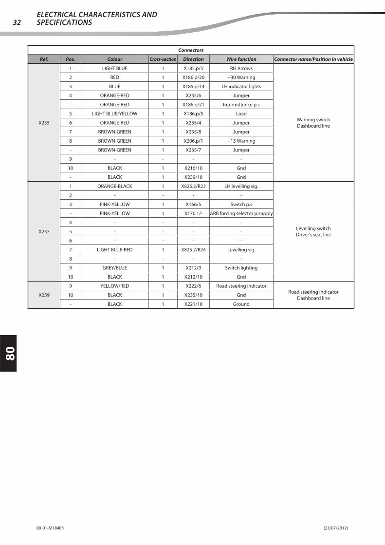
(23/07/2012)80-01-M184EN
80
32ELECTRICAL CHARACTERISTICS AND SPECIFICATIONS
Connectors
Ref. Pos. Colour Cross-section Direction Wire function Connector name/Position in vehicle
X235
1 LIGHT BLUE 1 X185.p/5 RH Arrows
Warning switch
Dashboard line
2 RED 1 X186.p/20 +30 Warning
3 BLUE 1 X185.p/14 LH indicator lights
4 ORANGE-RED 1 X235/6 Jumper
- ORANGE-RED 1 X186.p/21 Intermittence p.s
5 LIGHT BLUE/YELLOW 1 X186.p/5 Load
6 ORANGE-RED 1 X235/4 Jumper
7 BROWN-GREEN 1 X235/8 Jumper
8 BROWN-GREEN 1 X206.p/1 +15 Warning
- BROWN-GREEN 1 X235/7 Jumper
9 - - - -
10 BLACK 1 X216/10 Gnd
- BLACK 1 X239/10 Gnd
X237
1 ORANGE-BLACK 1 X825.2/R23 LH levelling sig.
Levelling switch
Driver's seat line
2 - - - -
3 PINK-YELLOW 1 X166/5 Switch p.s
- PINK-YELLOW 1 X170.1/- ARB forcing selector p.supply
4 - - - -
5 - - - -
6 - - - -
7 LIGHT BLUE-RED 1 X825.2/R24 Levelling sig.
8 - - - -
9 GREY/BLUE 1 X212/9 Switch lighting
10 BLACK 1 X212/10 Gnd
X239
9 YELLOW/RED 1 X222/6 Road steering indicatorRoad steering indicator
Dashboard line10 BLACK 1 X235/10 Gnd
- BLACK 1 X221/10 Ground

(23/07/2012) 80-01-M184EN
80
33ELECTRICAL CHARACTERISTICS AND
SPECIFICATIONS
Connectors
Ref. Pos. Colour Cross-section Direction Wire function Connector name/Position in vehicle
X256.p
1 YELLOW-BLACK 1 X825.2/L37 Cab sig.
Platform chassis line connection
connector
Driver's seat line
2 - - - -
3 GREEN-RED 1 X825.2/L36 Spare
4 WHITE 0.35 Sal 53/- Can H Open 1
5 GREEN 0.35 Sal52/- Can L Open 1
6 GREY-WHITE 1 X206.s/15Emergency mushroom out
(ignition)
7 WHITE 1 X733.s/A_C3 Emergency mushroom out
8 LIGHT BLUE-YELLOW 1 X733.s/A_C6Command for start-up from
shuttle
9 LIGHT BLUE-WHITE 1 Sal100/- Warning siren
10 GREY/BLACK 1 X733.s/A_C5 +15 platform
11 BLACK 1 Gnd5.2/- Gnd
12 WHITE/GREEN 1 X467/101450 RPM controlled speed
command
13 LIGHT BLUE/YELLOW 1 X467/4 Accelerate negative sig.
14 WHITE-YELLOW 1 X467/5 Decelerate negative sig.
15 YELLOW 1 X825.2/L27 Platform mushroom sig.
16 BLACK 1 Gnd5.2/- Gnd
17 YELLOW-RED 1 Sal39/- +VE
18 YELLOW-GREEN 1 X825.2/L38 Platform by-pass button
19 ORANGE-BLACK 1 X825.2/R21 Emergency pump sig.
20 BLUE-BLACK 1 X825.2/L39 Descent pr.switch
21 BLUE-YELLOW 1 X825.2/R5 Boom descent sol.v
22 BLUE 1 X825.2/R3 Boom ascent sol.v
23 GREY-RED 1 X825.1/16 Slewing sol.v
24 GREY-BLACK 1 X825.1/15 Slewing sol.v
25 YELLOW-BLACK 1 X825.1/2 Oil Switch sol.valve
26 RED 1 X733.s/A_C4 +30 boom
27 WHITE-GREEN 1 X899.1/1 Steering emergency pump
28 - - - -
29 - - - -
30 - - - -
31 PINK-YELLOW 1 X825.2/R34 Radio control sig.

(23/07/2012)80-01-M184EN
80
34ELECTRICAL CHARACTERISTICS AND SPECIFICATIONS
Connectors
Ref. Pos. Colour Cross-section Direction Wire function Connector name/Position in vehicle
X256.s
1 YELLOW-BLACK 1 X901.1/8 Cab sig.
Cab connector
Radio gripper platform line
2 - - - -
3 GREEN-RED 1 X916.s/H Spare
4 WHITE 0.35 Sa4/- Can H
5 GREEN 0.35 Sa2/- Can L
6 GREY-WHITE 1.5 Sa8/- Cab mushroom In
7 WHITE 1.5 Sa6/- Cab mushroom enabling
8 LIGHT BLUE-YELLOW 1 X914.2/28 Start up by radio control
9 LIGHT BLUE-WHITE 1 X914.2/30 Warning siren
10 GREY/BLACK 1 Sa1/- +15 Platform
11 BLACK 1.5 Sa7/- Ground
12 WHITE/GREEN 1 X915/1 1450 rpm speed sig.
13 LIGHT BLUE/YELLOW 1 X914.2/27 Decelerate sig.
14 WHITE-YELLOW 1 X914.2/26 Accelerate sig.
15 YELLOW 1 X956.s/2MC2-M platform mushroom
sig.
16 BLACK 1.5 Sa5/- Ground
17 YELLOW-RED 1 Sa9/- +VE
18 YELLOW-GREEN 1 X950.s/6 Reset sig.
19 ORANGE-BLACK 1 X957/86 Em. pump sig. from platform
20 BLUE-BLACK 1 X955.s/2 Descent press. sig.
21 BLUE-YELLOW 1 X908/1 Down sol.v
22 BLUE 1 X907/1 Up sol.v
23 GREY-RED 1 X906.s/1 Slewing 2 sol.v
24 GREY-BLACK 1 X905.s/1 Slewing 1 sol.v
25 YELLOW-BLACK 1 X904/1 Oil Switch sol.valve
26 - - - -
27 - - - -
28 - - - -
29 - - - -
30 - - - -
31 PINK-YELLOW 1 X901.1/2 Radio control sig.

(23/07/2012) 80-01-M184EN
80
35ELECTRICAL CHARACTERISTICS AND
SPECIFICATIONS
Connectors
Ref. Pos. Colour Cross-section Direction Wire function Connector name/Position in vehicle
X256.s
1 - - - -
X256.s capped counterfi gure
Driver's seat line
2 - - - -
3 - - - -
4 - - - -
5 - - - -
6 WHITE 1.5 X256.s/7 Electric stop jumper
7 WHITE 1.5 X256.s/6 Electric stop jumper
8 - - - -
9 - - - -
10 - - - -
11 - - - -
12 - - - -
13 - - - -
14 - - - -
15 - - - -
16 - - - -
17 - - - -
18 - - - -
19 - - - -
20 - - - -
21 - - - -
22 - - - -
23 - - - -
24 - - - -
25 - - - -
26 - - - -
27 - - - -
28 - - - -
29 - - - -
30 - - - -
31 - - - -
X280.s
1 GREY/BLUE 1 Sal33/- +15 OBD p.supply
OBD diagnosis socket
Driver's seat line
2 - - - -
3 WHITE 0.35 X826.s/6 Can-H J1939
4 - - - -
5 BLACK 0.5 X476/1 Gnd
6 YELLOW 0.5 Sal50/- Can H Open
7 GREY-GREEN 1 X476/14 Dig pin 12/2
8 BLUE-YELLOW 1 X476/5 Din engine ECU
9 GREY/BLUE 1 Sal33/- +15 OBD
10 - - - -
11 GREEN 0.35 X826.s/3 Can-L J1939
12 - - - -
13 - - - -
14 BLACK 0.5 Sal49/- Can L Open
15 - - - -
16 RED 0.5 X207/4 +30 OBD p.supply
X281.1 1 PINK-WHITE 1 X186.s/6Steering comp. low pressure
sig.
Steering compensator pressure
Driver's seat line

(23/07/2012)80-01-M184EN
80
36ELECTRICAL CHARACTERISTICS AND SPECIFICATIONS
Connectors
Ref. Pos. Colour Cross-section Direction Wire function Connector name/Position in vehicle
X281.21 BLACK 1 X478.2/1 Gnd Steering compensator pressure
Driver's seat line- BLACK 1 X198.2/1 Gnd
X3101 BLACK AWG22 X171.p/2 - ARB exclusion buzzer
Driver's seat line2 RED AWG22 X171.p/1 -
X464
1 RED 1 X733.s/A_D2 +30 engine control unit
Mercedes engine control unit
Driver's seat line
2 WHITE-GREEN 1.5 Sal38/- +15 ignition
3 BLACK 1.5 Gnd4.3/- Gnd
4 - - - -
5 YELLOW-BLUE 1 X185.s/17Engine general alarm
indicator
6 WHITE-BLACK 1 X185.s/18 Engine alert indicator
7 ORANGE-BLACK 1 X185.s/19 Spark plugs
8 - - - -
9 - - - -
10 - - - -
11 - - - -
12 BROWN-WHITE 0.5 X201/2 Accelerator pedal pin 2
13 GREY-WHITE 0.5 X201/4 Accelerator pedal pin 4
14 YELLOW 0.5 X201/3 Accelerator pedal pin 3
- YELLOW 0.5 X201/1 Accelerator pedal pin 1
15 RED-GREEN 1 X733.s/A_D3 85 Stop lights relay
- RED-GREEN 1 X478.1/1 Brakes negative sig.
16 GREEN-BLACK 1 X185.s/10 Parking brake indicator light
- GREEN-BLACK 1 X160.p/9 Parking brake sig.
17 - - - -
18 - - - -
19 WHITE 0.35 X826.s/4 Can-H J1939
- WHITE 0.35 X826.s/6 Can-H J1939
20 - - - -
21 GREEN 0.35 X826.s/1 Can-L J1939
- GREEN 0.35 X826.s/3 Can-L J1939
X465
1 GREY/BLUE 1 X733.s/A_D4 Enable start up
Mercedes engine control unit
Driver's seat line
- GREY/BLUE 1 X720.p/K Enable start up
2 GREY-GREEN 1 X476/14 Dig pin 12/2
3 WHITE 1 X185.s/21Engine oil pressure low
indicator
4 GREY-YELLOW 1 X186.s/1 Water temp. instrument sig.
5 - - - -
6 GREY-RED 1 X206.s/2 W alternator
7 - - - -
8 - - - -
9 - - - -
10 YELLOW/RED 1 X720.p/T Spark plugs feedback
11 - - - -
12 - - - -

(23/07/2012) 80-01-M184EN
80
37ELECTRICAL CHARACTERISTICS AND
SPECIFICATIONS
Connectors
Ref. Pos. Colour Cross-section Direction Wire function Connector name/Position in vehicle
X466
1 GREY-WHITE 1 X733.s/A_C7 Idle negative sig.
Mercedes engine control unit
Driver's seat line
2 - - - -
3 PURPLE/WHITE 1 X185.s/1 Odometer sig.
4 - - - -
5 BLUE-BLACK 0.5 X201/5 Accelerator pedal 5 pin
- BLUE-BLACK 0.5 X201/6 Accelerator pedal 6 pin
6 - - - -
7 - - - -
8 - - - -
9 ORANGE-WHITE 1 X720.p/A 85 preheating optional relay
10 - - - -
11 LIGHT BLUE-YELLOW 1 X733.s/A_B5 85 1200 rpm sol.v relay
12 BROWN-BLACK 1 X185.s/20High water temperature
indicator
13 YELLOW 1 X720.p/L Can H Mercedes
14 BROWN-RED 1 X720.p/P Gnd Can Mercedes
- BROWN-GREY 1 X720.p/J Gnd Can Mercedes
15 BLUE 1 X720.p/M Can L Mercedes
X467
1 PINK 0.5 X185.s/7 Engine oil level sig.
Mercedes engine control unit
Driver's seat line
2 - - - -
3 - - - -
4 LIGHT BLUE/YELLOW 1 X256.p/13 Accelerate negative sig.
5 WHITE-YELLOW 1 X256.p/14 Decelerate negative sig.
6 BLACK 1 Gnd4.3/- Ground
7 - - - -
8 - - - -
9 - - - -
10 WHITE/GREEN 1 X256.p/121450 RPM controlled speed
command
11 - - - -
12 - - - -
13 - - - -
14 - - - -
15 - - - -
16 - - - -
17 - - - -
18 - - - -
X468.1 - RED 16 X740.p/1 +3030 services relay
Control unit line
X468.21 BLUE/WHITE 1 X732.p/B8 86 services relay Services relay coil
Control unit line2 BLACK 1 Sal4/- Gnd
X468.3- WHITE 8 Sal1/- +15 87 services relay
Control unit line- WHITE 8 +15.1/- +15 service
X473
1 BLACK 1.5 Gnd4.1/- Gnd
LH head light
Driver's seat line
2 GREY-BLACK 1 X733.s/A_D6 LH front dipped beam
3 GREEN-BLACK 1 X733.s/A_D5 LH main beam
4 YELLOW 1 Sal29/- Position light
5 BLUE 1 X191/9 LH direction light
6 - - - -

(23/07/2012)80-01-M184EN
80
38ELECTRICAL CHARACTERISTICS AND SPECIFICATIONS
Connectors
Ref. Pos. Colour Cross-section Direction Wire function Connector name/Position in vehicle
X474
85 BLACK 1 Sal4/- Gnd
Relay box
Control unit line
86 WHITE 1 X7.s/13 86 VP relay
30 BROWN 4 X474/4b Rexroth control unit p.s
87 LIGHT BLUE 4 Sal5/- P.supply +VP
1a RED 1 Sal2/- +30
1b RED 1 X733.p/A_D2 +30 engine control unit
2a RED 1 Sal2/- +30
2b RED 1 X732.p/D5 +30 engine diagnosis
3a RED 1 Sal2/- +30
3b RED 1 X732.p/D6 +30 vehicle radio
4a WHITE 4 Sal1/- +15
4b BROWN 4 X474/30 Rexroth control unit p.s
5a RED 1 Sal2/- +30
5b RED 1 X733.p/A_C4 +30
6a WHITE 1 Sal1/- +15
6b WHITE-BLACK 1 X732.p/C5 +15 engine diagnosis
7a WHITE 1.5 Sal1/- +15
7b LIGHT BLUE-GREEN 1.5 X733.p/A_D8 Fuel oil fi lter heater
8a WHITE 1.5 Sal1/- +15
8b WHITE-BLACK 1.5 X732.p/D8 Front work lights switch p.s
9a WHITE 1 Sal1/- +15
9b GREY/BLACK 1 X733.p/A_C5 +15 platform
10a WHITE 1 Sal1/- +15
10b LIGHT BLUE/BLACK 1 X732.p/B1 +15 brake emergency kit
X476
1 BLACK 0.5 X280.s/5 Gnd
Mercedes Diagnostics
Driver's seat line
- BLACK 0.5 Gnd5.2/- Gnd
2 WHITE-BLACK 1 X732.s/C5 +15 engine diagnosis
3 RED 1 X732.s/D5 +30 engine diagnosis
4 - - - -
5 BLUE-YELLOW 1 X280.s/8 Din engine ECU
- BLUE-YELLOW 1 X720.p/S Dig. Engine ECU
6 - - - -
7 - - - -
8 - - - -
9 - - - -
10 - - - -
11 - - - -
12 - - - -
13 - - - -
14 GREY-GREEN 1 X280.s/7 Dig pin 12/2
- GREY-GREEN 1 X465/2 Dig pin 12/2
X478.1 1 RED-GREEN 1 X464/15 Brakes negative sig.Stop lights pressure switch
Driver's seat line
X478.21 BLACK 1 X281.2/1 Gnd Stop lights pressure switch
Driver's seat line- BLACK 1 X899.2/1 Gnd
X484.p1 - - - - Counterfi gure resistance
Dashboard line2 - - - -
X484.s
1 PINK-BLACK 1 X185.p/15 D+ alternatorAlternator resistance connector
Dashboard line- PINK-BLACK 0.5 X501/18 D+
2 GREY/BLUE 1 Sal35/- +15 p.s.

(23/07/2012) 80-01-M184EN
80
39ELECTRICAL CHARACTERISTICS AND
SPECIFICATIONS
Connectors
Ref. Pos. Colour Cross-section Direction Wire function Connector name/Position in vehicle
X501
1 GREY-BROWN 0.5 X206.p/11 Fuel reserve indicator
Eco instrument
Dashboard line
2 YELLOW-BLUE 0.5 X185.p/12 Rear axle indicator
3 LIGHT BLUE-WHITE 0.5 X185.p/8 Front axle indicator
4 BROWN 0.5 X222/1 4-wheel steer. ind.
5 BROWN-BLACK 0.5 X185.p/20 Water temp. max. indicator
6 - - - -
7 YELLOW 0.5 X206.p/8 Position lights indicator
8 BLUE-RED 0.5 X186.p/3 Diff erential block indicator
9 PURPLE 0.5 X206.p/12 +15 ECO instrument
10 WHITE-BLACK 0.5 X185.p/18 Mercedes alarm indicator
11 - - - -
12 GREEN-WHITE 0.5 X228/C1 Main beams indicator
13 GREY-YELLOW 0.5 X186.p/1 Water temperature sig.
14 RED-BLACK 0.5 X206.p/19 Rexroth error indicator
15 GREY-RED 0.5 X206.p/2 RPM signal
16 BLACK 0.5 Sal36/- Gnd
17 ORANGE-BLACK 0.5 X185.p/19 Preheating indicator
18 PINK-BLACK 0.5 X484.s/1 D+
19 BLUE-WHITE 0.5 X206.p/7 Direction lights indicator
20 ORANGE 0.5 X206.p/5 Fuel level sig.
21 WHITE 0.5 X185.p/21 Engine oil indicator
22 GREEN-BLACK 0.5 X185.p/10 Parking brake indicator
23 WHITE-BLUE 0.5 X186.p/4Brakes fl uid level low
indicator light
24 YELLOW-RED 0.5 X228/B5 Positions indicator
25 PINK-WHITE 0.5 X186.p/6 Steering fault indicator light
26 GREY-YELLOW 0.5 X185.p/16 Air fi lter clogged ind.
27 GREY-BLUE 0.5 X206.p/18 ARB forcing sig.
28 YELLOW-BLUE 0.5 X185.p/17 Mercedes alarm indicator
29 ORANGE 0.5 X222/5 Crab steering indicator
30 - - - -
31 - - - -
32 - - - -
33 - - - -
34 - - - -
35 - - - -
36 - - - -
X6111 LIGHT BLUE/WHITE 1 X128.s/33 VRD sol.v (Slow-Motion) VRD solenoid valve
Rear line2 BLACK 1 Gnd2/- Gnd
X6331 PURPLE/BLACK 1 X128.s/34 VS sol.v (slewing) VS solenoid valve
Rear line2 BLACK 1 Gnd2/- Gnd
X675.p
1 - - - -
Connector to X675.p
Rear line
2 - - - -
3 - - - -
4 - - - -
5 - - - -
6 - - - -
7 - - - -
8 - - - -

(23/07/2012)80-01-M184EN
80
40ELECTRICAL CHARACTERISTICS AND SPECIFICATIONS
Connectors
Ref. Pos. Colour Cross-section Direction Wire function Connector name/Position in vehicle
X675.s
1 BLUE 1 Sal20/- LH direction light
Trailer socket kit
Rear line
2 YELLOW-RED 1 Sal12/- Trailer reversing light
3 BLACK 1 Gnd3/- Gnd
4 LIGHT BLUE 1 Sal18/- RH direction light
5 YELLOW-BLACK 1 Sal21/- Trailer LH position light
6 RED-YELLOW 1 Sal14/- Trailer stop light
7 YELLOW 1 Sal17/- Trailer RH position light
8 WHITE/RED 1 Sal13/- Trailer rear fog lamp
X700
1 WHITE 1 X701/1 Forwards/Reverse sig.Forwards diode
Control unit line- WHITE 1 X5.s/10 Forwards/Reverse sig.
2 PURPLE-BLACK 1 X733.p/B_B3 Forwards command
X701
1 WHITE 1 X4.s/6 Forwards/Reverse sig.Reversing diode
Control unit line- WHITE 1 X700/1 Forwards/Reverse sig.
2 GREEN-WHITE 1 X733.p/B_B7 Reversing command
X7021 GREY 2.5 X706/87
Electric fan 1 fuse power
supply Electric fan 1 fuse
Motor line2 ORANGE 2.5 X717/A Electric fan 1 p.supply
X703
1 GREY 2.5 X706/87 Electric fan 2 p.supplyElectric fan 2 fuse
Motor line2 YELLOW 2.5 X718/AElectric fan 2 fuse power
supply
X704
1 WHITE 2.5 X735/87 Electric fan 3 p.supplyElectric fan 3 fuse
Motor line2 BLUE 2.5 X719/AElectric fan 3 fuse power
supply
X7051 WHITE 2.5 X735/87
Electric fan 4 fuse power
supply Electric fan 4 fuse
Motor line2 BROWN 2.5 X720/A Electric fan 4 p.supply
X706
85 BLACK 1 X735/85 Gnd
Electric fans 1 and 2 relay
Motor line
- BLACK 1 Gnd2/- Gnd
86 ORANGE-YELLOW 1 X720.s/V 86 electric fans unit 1 relay
30 RED 6 Sal5/- 30 Electric fans 1 and 2 relay
87 GREY 2.5 X702/1Electric fan 1 fuse power
supply
- GREY 2.5 X703/1Electric fan 2 fuse power
supply
X709
1 RED 2.5 Sal5/-P.supply + 30 fuse p.s ECU
MercedesECU Mercedes +30 fuse
Motor line2 RED-BLACK 2.5 X716/5 +30 engine control unit
- RED-BLACK 2.5 X716/6 +30 engine control unit
X711
F1 RED 4 X720.s/D +30 optional p.s
Fusebox
Motor line
F2 RED 6 X725.s/2+30 fuses and relay control
unit
F3 RED 4 X751/30 30 start-up relay
F4 RED 6 X725.s/1 +30 start-up panel
COM RED 25 +30/- -
X7141 PINK-BLACK 1 X720.s/R D+ alternator D+ alternator
Motor line2 - - - -
X715 - LIGHT BLUE 4 X751/87 +50 start+50 start
Motor line
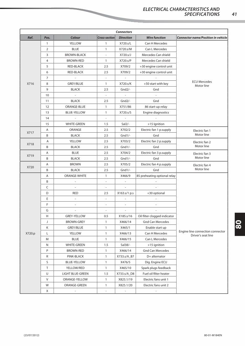
(23/07/2012) 80-01-M184EN
80
41ELECTRICAL CHARACTERISTICS AND
SPECIFICATIONS
Connectors
Ref. Pos. Colour Cross-section Direction Wire function Connector name/Position in vehicle
X716
1 YELLOW 1 X720.s/L Can H Mercedes
ECU Mercedes
Motor line
2 BLUE 1 X720.s/M Can L Mercedes
3 BROWN-BLACK - X720.s/J Mercedes Can shield
4 BROWN-RED 1 X720.s/P Mercedes Can shield
5 RED-BLACK 2.5 X709/2 +30 engine control unit
6 RED-BLACK 2.5 X709/2 +30 engine control unit
7 - - - -
8 GREY/BLUE 1 X720.s/K +50 start with key
9 BLACK 2.5 Gnd2/- Gnd
10 - - - -
11 BLACK 2.5 Gnd2/- Gnd
12 ORANGE-BLUE 1 X751/86 86 start-up relay
13 BLUE-YELLOW 1 X720.s/S Engine diagnostics
14 - - - -
15 WHITE-GREEN 1.5 Sal2/- +15 Ignition
X717A ORANGE 2.5 X702/2 Electric fan 1 p.supply Electric fan 1
Motor lineB BLACK 2.5 Gnd1/- Gnd
X718 A YELLOW 2.5 X703/2 Electric fan 2 p.supply Electric fan 2
Motor lineB BLACK 2.5 Gnd1/- Gnd
X719A BLUE 2.5 X704/2 Electric fan 3 p.supply Electric fan 3
Motor lineB BLACK 2.5 Gnd1/- Gnd
X720A BROWN 2.5 X705/2 Electric fan 4 p.supply Electric fan 4
Motor lineB BLACK 2.5 Gnd1/- Gnd
X720.p
A ORANGE-WHITE 1 X466/9 85 preheating optional relay
Engine line connection connector
Driver's seat line
B - - - -
C - - - -
D RED 2.5 X163.s/1 p.s +30 optional
E - - - -
F - - - -
G - - - -
H GREY-YELLOW 0.5 X185.s/16 Oil fi lter clogged indicator
J BROWN-GREY 1 X466/14 Gnd Can Mercedes
K GREY/BLUE 1 X465/1 Enable start up
L YELLOW 1 X466/13 Can H Mercedes
M BLUE 1 X466/15 Can L Mercedes
N WHITE-GREEN 1.5 Sal38/- +15 ignition
P BROWN-RED 1 X466/14 Gnd Can Mercedes
R PINK-BLACK 1 X733.s/A_B7 D+ alternator
S BLUE-YELLOW 1 X476/5 Dig. Engine ECU
T YELLOW/RED 1 X465/10 Spark plugs feedback
U LIGHT BLUE-GREEN 1.5 X733.s/A_D8 Fuel oil fi lter heater
V ORANGE-YELLOW 1 X825.1/19 Electric fans unit 1
W ORANGE-GREEN 1 X825.1/20 Electric fans unit 2
X - - - -
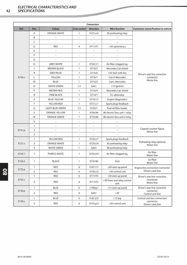
(23/07/2012)80-01-M184EN
80
42ELECTRICAL CHARACTERISTICS AND SPECIFICATIONS
Connectors
Ref. Pos. Colour Cross-section Direction Wire function Connector name/Position in vehicle
X720.s
A ORANGE-WHITE 1 X721.s/2 85 preheating relay
Driver's seat line conection
connector
Motor line
B - - - -
C - - - -
D RED 4 X711/F1 +30 optional p.s
E - - - -
F - - - -
G - - - -
H GREY-WHITE 1 X724.1/1 Air fi lter clogged sig.
J BROWN-BLACK 1 X716/3 Mercedes Can shield
K GREY/BLUE 1 X716/8 +50 start with key
L YELLOW 1 X716/1 Can H Mercedes
M BLUE 1 X716/2 Can L Mercedes
N WHITE-GREEN 1.5 Sal2/- +15 Ignition
P BROWN-RED 1 X716/4 Mercedes Can shield
R PINK-BLACK 1 X714/1 D+ alternator
S BLUE-YELLOW 1 X716/13 Engine diagnostics
T YELLOW/RED 1 X721.s/1 Spark plugs feedback
U LIGHT BLUE-GREEN 1.5 X10⁵/1 Fuel oil fi lter heater
V ORANGE-YELLOW 1 X706/86 86 electric fans unit 1 relay
W ORANGE-GREEN 1 X735/86 86 electric fans unit 2 relay
X - - - -
X721.p
1 - - - -Capped counter-fi gure
Motor line2 - - - -
3 - - - -
X721.s
1 YELLOW/RED 1 X720.s/T Spark plugs feedbackPreheating relay optional
Motor line2 ORANGE-WHITE 1 X720.s/A 85 preheating relay
3 WHITE-GREEN 1 Sal2/- 86 preheating relay
X724.1 1 PURPLE-WHITE 1 X720.s/H Air fi lter clogged sig.Air fi lter
Motor line
X724.2 1 BLACK 1 X735/85 GndAir fi lter
Motor line
X725.p1 RED 6 X187.1/1 +30 start-up panel Engine line connection connector
Driver's seat line2 RED 6 X730.s/2 +30 control unit
X725.s
1 RED 6 X711/F4 +30 start-up panel Driver's seat line conection
connector
Motor line2 RED 6 X711/F2+30 fuses and relay control
unit
X730.p
1 BLUE 6 +15Key/- +15 start-up panel Driver's seat line conection
connector
Control unit line2 RED 6 Sal3/- +30
X730.s
1 BLUE 6 X187.2/5 +15 key Control unit box connection
connector
Driver's seat line2 RED 6 X725.p/2 +30 control unit
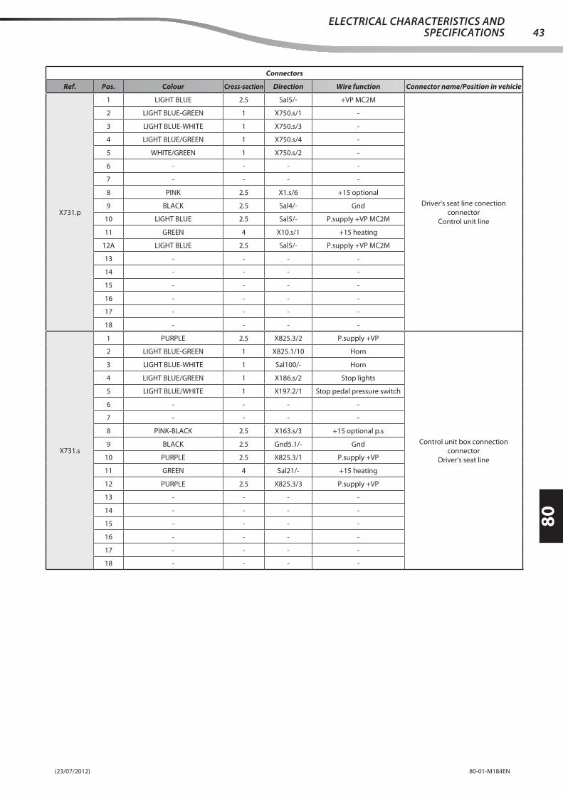
(23/07/2012) 80-01-M184EN
80
43ELECTRICAL CHARACTERISTICS AND
SPECIFICATIONS
Connectors
Ref. Pos. Colour Cross-section Direction Wire function Connector name/Position in vehicle
X731.p
1 LIGHT BLUE 2.5 Sal5/- +VP MC2M
Driver's seat line conection
connector
Control unit line
2 LIGHT BLUE-GREEN 1 X750.s/1 -
3 LIGHT BLUE-WHITE 1 X750.s/3 -
4 LIGHT BLUE/GREEN 1 X750.s/4 -
5 WHITE/GREEN 1 X750.s/2 -
6 - - - -
7 - - - -
8 PINK 2.5 X1.s/6 +15 optional
9 BLACK 2.5 Sal4/- Gnd
10 LIGHT BLUE 2.5 Sal5/- P.supply +VP MC2M
11 GREEN 4 X10.s/1 +15 heating
12A LIGHT BLUE 2.5 Sal5/- P.supply +VP MC2M
13 - - - -
14 - - - -
15 - - - -
16 - - - -
17 - - - -
18 - - - -
X731.s
1 PURPLE 2.5 X825.3/2 P.supply +VP
Control unit box connection
connector
Driver's seat line
2 LIGHT BLUE-GREEN 1 X825.1/10 Horn
3 LIGHT BLUE-WHITE 1 Sal100/- Horn
4 LIGHT BLUE/GREEN 1 X186.s/2 Stop lights
5 LIGHT BLUE/WHITE 1 X197.2/1 Stop pedal pressure switch
6 - - - -
7 - - - -
8 PINK-BLACK 2.5 X163.s/3 +15 optional p.s
9 BLACK 2.5 Gnd5.1/- Gnd
10 PURPLE 2.5 X825.3/1 P.supply +VP
11 GREEN 4 Sal21/- +15 heating
12 PURPLE 2.5 X825.3/3 P.supply +VP
13 - - - -
14 - - - -
15 - - - -
16 - - - -
17 - - - -
18 - - - -

(23/07/2012)80-01-M184EN
80
44ELECTRICAL CHARACTERISTICS AND SPECIFICATIONS
Connectors
Ref. Pos. Colour Cross-section Direction Wire function Connector name/Position in vehicle
X732.p
A1 ORANGE-BLUE 1.5 X3.s/8 Indicator stalk lights p.s
Driver's seat line conection
connector
Control unit line
A2 BROWN-BLACK 1 X7.s/18 Boom functions switch p.s
A3 ORANGE-BLACK 1 X3.s/4 Seat compressor p.supply
A4 WHITE/GREEN 1 X3.s/4 +15 vehicle radio
A5 - - - -
A6 ORANGE-WHITE 1 X4.s/9 Transmission release
A7 WHITE/BLACK 1 X4.s/8 86 main beams relay
A8 WHITE-GREEN 1.5 X4.s/7 +15 ignition
B1 LIGHT BLUE/BLACK 1 X474/10b +15 brake emergency kit
B2 BLACK-PURPLE 1 X4.s/4 Emergency mushroom p.s
B3 - - - -
B4 BROWN-GREEN 1 X1.s/14 +15 warning switch
B5 GREY/BLUE 1 X1.s/16Vehicle functions control
unit power supply
B6 - - - -
B7 LIGHT BLUE/WHITE 1 X1.s/15 Rotating beacon switch p.s.
B8 BLUE/WHITE 1 X468.2/1 86 services relay
C1 - - - -
C2 YELLOW-BLACK 1 X1.s/13 Backlighting
C3 - - - -
C4 GREY/BLUE 1 X1.s/8 Seat micro p.supply
C5 WHITE-BLACK 1 X474/6b +15 engine diagnosis
C6 YELLOW-RED 1 X1.s/2 +15 OBD p.supply
C7 - - - -
C8 RED 1 X1.s/1 +30 warning
D1 GREY-RED 1.5 X1.s/5Position lights from indicator
stalk
D2 GREY-GREEN 1 X2.s/3 ARB system p.supply
D3 WHITE-RED 1 X2.s/2 Reset switch p.s.
D4 GREEN 1 X2.s/1 Main beams indicator
D5 RED 1 X474/2b +30 engine diagnosis
D6 RED 1 X474/3b +30 vehicle radio
D7 BLUE/RED 1 X1.s/11 Reverse fan system p.supply
D8 WHITE-BLACK 1.5 X474/8b Front work lights switch p.s

(23/07/2012) 80-01-M184EN
80
45ELECTRICAL CHARACTERISTICS AND
SPECIFICATIONS
Connectors
Ref. Pos. Colour Cross-section Direction Wire function Connector name/Position in vehicle
X732.s
A1 ORANGE-BLUE 1.5 Sal19/- Indicator stalk lights p.s
Control unit box connection
connector
Driver's seat line
A2 BROWN-BLACK 1 X208/5 Boom functions switch p.s
A3 ORANGE-BLACK 1 X172.s/1 Seat compressor p.supply
A4 WHITE/GREEN 1 X207/7 +15 vehicle radio
A5 - - - -
A6 ORANGE-WHITE 1 X825.1/3 Transmission release
A7 WHITE/BLACK 1 X191/4 86 main beams relay
A8 WHITE-GREEN 1.5 Sal38/- +15 ignition
B1 LIGHT BLUE/BLACK 1 X224.s/A +15 brake emergency kit
B2 BLACK-PURPLE 1 X206.s/14 Emergency mushroom p.s
B3 - - - -
B4 BROWN-GREEN 1 X206.s/1 +15 warning switch
B5 GREY/BLUE 1 Sal35/- Vehicle functions control
unit power supply
B6 - - - -
B7 LIGHT BLUE/WHITE 1 X164.s/6 Rotating beacon switch p.s.
B8 BLUE/WHITE 1 X187.2/6 86 services relay
C1 BLACK 1 Gnd4.2/- Gnd
C2 YELLOW-BLACK 1 X178.2/1 Backlighting
C3 BLACK 1 Gnd4.2/- Gnd
C4 GREY/BLUE 1 X173.1/1 Seat micro p.supply
C5 WHITE-BLACK 1 X476/2 +15 engine diagnosis
C6 YELLOW-RED 1 Sal39/- MC2M electronics p.supply
C7 - - - -
C8 RED 1 X186.s/20 +30 warning
D1 GREY-RED 1.5 X191/2Position lights from indicator
stalk
D2 GREY-GREEN 1 X210/2 ARB system p.supply
D3 WHITE-RED 1 X186.s/8 Reset switch p.s.
D4 GREEN 1 X206.s/9 Main beams indicator
D5 RED 1 X476/3 +30 engine diagnosis
D6 RED 1 X207/4 +30 vehicle radio
D7 - - - -
D8 WHITE-BLACK 1.5 X164.s/5 Front work lights switch p.s

(23/07/2012)80-01-M184EN
80
46ELECTRICAL CHARACTERISTICS AND SPECIFICATIONS
Connectors
Ref. Pos. Colour Cross-section Direction Wire function Connector name/Position in vehicle
X733.p
A_A1 PINK-BLACK 1.5 X3.s/5 Front w.wipers p.supply
Driver's seat line conection
connector
Control unit line
A_A2 PINK-YELLOW 1 X2.s/5 Axles sensors p.s
A_A3 BLUE-YELLOW 1 X3.s/10 Rear w.wipers indicator stalk p.s
A_A4 YELLOW 1 X1.s/12 RH rear position light
A_A5 YELLOW-BLACK 1 X1.s/13 LH rear position light
A_A6 GREEN/WHITE 1 X7.s/3 Forward movt. sol.v
A_A7 LIGHT BLUE/WHITE 1 X7.s/14 Reversing sol.v
A_A8 GREY-BLUE 1.5 X8.s/10 Warning siren
A_B1 GREEN 1 X3.s/6 RH main beam
A_B2 - - - -
A_B3 BLUE-RED 1 X5.s/5 Diff erential block sol.valve
A_B4 - - - -
A_B5 LIGHT BLUE-YELLOW 1 X8.s/15 85 1200 rpm sol.v relay
A_B6 PINK-WHITE 1 X8.s/12 1200 rpm sol.v
A_B7 PINK-BLACK 1 X733.p/B_D4 D+ alternator
A_B8 GREY 1 X7.s/9 RH dipped beam
A_C1 ORANGE/WHITE 1 X8.s/7 Speed change command
A_C1 ORANGE/WHITE 1 X8.s/7 Speed change command
A_C2 - - - -
A_C3 WHITE 1 X7.s/13 Emergency mushroom out
A_C4 RED 1 X474/5b +30
A_C5 GREY/BLACK 1 X474/9b +15 platform
A_C6 LIGHT BLUE-YELLOW 1 X8.s/2 Start-up command
A_C7 GREY-WHITE 1 X5.s/1 Idle negative sig.
A_C8 BLUE-YELLOW 1 X3.s/10 Rear demister p.supply
A_D1 RED 1.5 X1.s/10 +30 socket
A_D2 RED 1 X474/1b +30 engine control unit
A_D3 RED-GREEN 1 X11.s/2 85 Stop lights relay
A_D4 GREY/BLUE 1 X8.s/1 Enable start up
A_D5 GREEN-BLACK 1 X2.s/4 LH main beam
A_D6 GREY-BLACK 1 X7.s/19 LH front dipped beam
A_D7 PURPLE 1 X7.s/21 RPM instrument p.supply
A_D8 LIGHT BLUE-GREEN 1.5 X474/7b Fuel oil fi lter heater
B_A1 LIGHT BLUE-YELLOW 1.5 X3.s/9Boom lights and cab
w.screen wipers lights p.s
B_A2 PINK/BLACK 1 X7.s/20 86 dipped beams relay
B_A3 GREY 1 X7.s/10 Dipped beams indicator
B_A4 BLUE/BLACK 1 X7.s/17 ARB sig.
B_A5 PINK-BLUE 1 X7.s/16 Speed reset indicator
B_A6 WHITE-YELLOW 1 X7.s/12 Mushroom IN transfer p.s
B_A7 GREY/BLUE 1 X7.s/11 Switch lighting
B_A8 RED-GREEN 1.5 X1.s/9Rear work lights switch
p.supply
B_B1 BROWN-BLACK 1 X7.s/8 Boom functions relay 30 p.s
B_B2 - - - -
B_B3 PURPLE-BLACK 1 X700/2 Forwards command
B_B4 - - - -
B_B5 PURPLE/WHITE 1 X4.s/5 Reversing command out
B_B6 PURPLE-WHITE 1 X7.s/1 Horn button p.supply
B_B7 GREEN-WHITE 1 X701/2 Reversing command
B_B8 YELLOW-RED 1 X7.s/15 Reversing light

(23/07/2012) 80-01-M184EN
80
47ELECTRICAL CHARACTERISTICS AND
SPECIFICATIONS
Connectors
Ref. Pos. Colour Cross-section Direction Wire function Connector name/Position in vehicle
X733.p
B_C1 RED-YELLOW 1 X11.s/7 Brake pedal sig.
Driver's seat line conection
connector
Control unit line
B_C2 ORANGE 1 X7.s/5Forward movement
command out
B_C3 LIGHT BLUE/WHITE 1 X11.s/1 86 speed change relay
B_C4 ORANGE-RED 1 X8.s/17 Intermittence p.s
B_C5 BLUE/WHITE 1 X8.s/16 Direction lights indicator
B_C6 BROWN-GREEN 1 X8.s/11 Neutral position
B_C7 LIGHT BLUE/YELLOW 1 X8.s/9 Intermittence charge
B_C8 BROWN-WHITE 1 X8.s/8 Low speed indicator
B_D1 GREY-BLACK 1.5 X11.s/5Mix. bucket switch and
double/triple out. p.s
B_D2 LIGHT BLUE-BLACK 1 X8.s/6 High speed indicator
B_D3 GREY-RED 1 X8.s/5 Steering selector p.supply
B_D4 PINK-BLACK 1 X733.p/A_B7 D+ alternator
B_D5 LIGHT BLUE-YELLOW 1 X8.s/2 +50 start
B_D6 WHITE/GREEN 1 X5.s/12 86 diff erential block relay
B_D7 LIGHT BLUE-WHITE 1 X3.s/11 Warning siren
B_D7 LIGHT BLUE-WHITE 1 X3.s/11 Warning siren
B_D8 BROWN-WHITE 1.5 X3.s/3Boom lights and cab
w.screen wipers lights p.s
X733.s
A_A1 PINK-BLACK 1.5 X188/3 Front w.wipers p.supply
Control unit box connection
connector
Driver's seat line
A_A2 PINK-YELLOW 1 Sal36/- Sensors p.supply
A_A3 BLUE-YELLOW 1 X192/1 Rear w.wipers indicator stalk p.s
A_A4 YELLOW 1 Sal29/- Position light
A_A5 YELLOW-BLACK 1 Sal37/- Position light
A_A6 GREEN/WHITE 1 X160.p/5 Forward movt. sol.v
A_A7 LIGHT BLUE/WHITE 1 X160.p/6 Reversing sol.v
A_A8 GREY-BLUE 1.5 X119.1/1 Warning siren
A_B1 GREEN 1 X160.p/24 RH main beam
A_B2 - - - -
A_B3 BLUE-RED 1 X206.s/6 Diff erential block sol.valve
A_B4 - - - -
A_B5 LIGHT BLUE-YELLOW 1 X466/11 85 1200 rpm sol.v relay
A_B6 PINK-WHITE 1 X160.p/7 1200 rpm sol.v
A_B7 PINK-BLACK 1 X720.p/R D+ alternator
A_B8 GREY 1 X160.p/22 RH dipped beam
A_C1 ORANGE/WHITE 1 X186.s/16 Speed change command
A_C2 - - - -
A_C3 WHITE 1 X256.p/7 Emergency mushroom out
A_C4 RED 1 X256.p/26 +30 boom
A_C5 GREY/BLACK 1 X256.p/10 +15 platform
A_C6 LIGHT BLUE-YELLOW 1 X256.p/8Command for start-up from
shuttle
A_C7 GREY-WHITE 1 X466/1 Idle negative sig.
A_C8 BLUE-YELLOW 1 X164.s/11 Rear demister p.supply
A_D1 RED 1.5 X178.1/1 +30 socket
A_D2 RED 1 X464/1 +30 engine control unit
A_D3 RED-GREEN 1 X464/15 85 Stop lights relay
A_D4 GREY/BLUE 1 X465/1 Enable start up
A_D5 GREEN-BLACK 1 X473/3 LH main beam
A_D6 GREY-BLACK 1 X473/2 LH front dipped beam

(23/07/2012)80-01-M184EN
80
48ELECTRICAL CHARACTERISTICS AND SPECIFICATIONS
Connectors
Ref. Pos. Colour Cross-section Direction Wire function Connector name/Position in vehicle
X733.s
A_D7 PURPLE 1 X206.s/12 RPM instrument p.supply
Control unit box connection
connector
Driver's seat line
A_D8 LIGHT BLUE-GREEN 1.5 X720.p/U Fuel oil fi lter heater
B_A1 LIGHT BLUE-YELLOW 1.5 X164.s/3 Roof and sides wiper switch p.s
B_A2 PINK/BLACK 1 X191/3 86 dipped beams relay
B_A3 GREY 1 X206.s/10 Dipped beams indicator
B_A4 - - - -
B_A5 PINK-BLUE 1 X185.s/13 Speed reset indicator
B_A6 WHITE-YELLOW 1 X206.s/20 Mushroom IN transfer p.s
B_A7 GREY/BLUE 1 X166/9 Switch lighting
B_A8 RED-GREEN 1.5 X164.s/7Rear work lights switch
p.supply
B_B1 - - - -
B_B2 - - - -
B_B3 PURPLE-BLACK 1 Sal55/- Forwards command
B_B4 - - - -
B_B5 PURPLE/WHITE 1 X825.2/R17 Reversing command out
B_B6 PURPLE-WHITE 1 X191/5 Horn button p.supply
B_B7 GREEN-WHITE 1 Sal56/- Reversing movement command
B_B8 YELLOW-RED 1 X128.p/12 Reversing light
B_C1 RED-YELLOW 1 Sal101/- Brake pedal
B_C2 ORANGE 1 X825.2/R16Forward movement
command out
B_C3 LIGHT BLUE/WHITE 1 X197.2/1 86 speed change relay
B_C4 ORANGE-RED 1 X186.s/21 Intermittence p.s
B_C5 BLUE/WHITE 1 X206.s/7 Direction lights indicator
B_C6 BROWN-GREEN 1 X197.1/1 Neutral position
B_C7 LIGHT BLUE/YELLOW 1 X186.s/5 Intermittence charge
B_C8 BROWN-WHITE 1 X186.s/17 Low speed indicator
B_D1 GREY-BLACK 1.5 Sal24/-Mix. bucket switch and
double/triple out. p.s
B_D2 LIGHT BLUE-BLACK 1 X186.s/18 High speed indicator
B_D3 GREY-RED 1 X186.s/19 Steering selector p.supply
B_D4 PINK-BLACK 1 X185.s/15 D+ alternator
B_D5 LIGHT BLUE-YELLOW 1 X187.2/7 +50 start
B_D6 WHITE/GREEN 1 X185.s/11 86 diff erential block relay
B_D7 LIGHT BLUE-WHITE 1 X191/6 86 warning siren relay
B_D8 BROWN-WHITE 1.5 X164.s/15 Boom work lights switch p.s
X735
85 BLACK 1 X724.2/1 Gnd
Electric fans 3 and 4 relay
Motor line
- BLACK 1 X706/85 Gnd
86 ORANGE-GREEN 1 X720.s/W 86 electric fans unit 2 relay
30 RED 6 Sal5/- 30 Electric fans relay 3 and 4
87 WHITE 2.5 X705/1 Electric fan 4 fuse power supply
- WHITE 2.5 X704/1 Electric fan 3 fuse power supply
X740.p 1 RED 16 X468.1/- +30Driver's seat line conection connector
Control unit line
X740.s 1 RED 16 X755/- +30Control unit line connection connector
Cab power supply line
X750.p
1 - - - -
Diodes counterfi gure
Control unit line
2 - - - -
3 - - - -
4 - - - -

(23/07/2012) 80-01-M184EN
80
49ELECTRICAL CHARACTERISTICS AND
SPECIFICATIONS
Connectors
Ref. Pos. Colour Cross-section Direction Wire function Connector name/Position in vehicle
X750.s
1 LIGHT BLUE-GREEN 1 X731.p/2 -
Diodes connector
Control unit line
2 WHITE/GREEN 1 X731.p/5 -
3 LIGHT BLUE-WHITE 1 X731.p/3 -
4 LIGHT BLUE/GREEN 1 X731.p/4 -
X751
85 BLACK 1 Gnd2/- Gnd
Start-up relay
Motor line
86 ORANGE-BLUE 1 X716/12 86 start-up relay
30 RED 4 X711/F3 30 start-up relay
87 LIGHT BLUE 4 X715/- +50 start
X755 - RED 16 X740.s/1 +30+30
Cab power supply line
X755.p1 - - - - Cap
Front line2 - - - -
X755.s1 PINK-YELLOW 1 Sal1/- Diff erential micro ps Diff erential block micro
Front line2 WHITE 1 X160.s/1 Diff . micro block sig.
X756.p1 - - - - Cap
Front line2 - - - -
X756.s1 YELLOW-BLACK 1 Sal2/- RH front side marker lamp RH front side markers lamps
Front line2 BLACK 1 Gnd1.2/- Ground
X757.p1 - - - - Cap
Rear line2 - - - -
X757.s1 YELLOW-BLACK 1 Sal21/- LH rear side marker lamp LH rear side marker lamps
Rear line2 BLACK 1 Gnd3/- Gnd
X758.p1 - - - - Cap
Rear line2 - - - -
X758.s1 YELLOW 1 Sal17/- RH rear side marker lamp RH rear side marker lamps
Rear line2 BLACK 1 Gnd3/- Gnd
X760.p1 - - - - Cap
Driver's seat line2 - - - -
X760.s1 YELLOW 1 Sal29/- LH front side marker lamps LH front side marker lamps
Driver's seat line2 BLACK 1 Gnd4.1/- Ground
X761.p1 Cap
Driver's seat line2
X761.s1 RED-YELLOW 1 Sal101/- Brake sig. Connector
Driver's seat line2 WHITE-BLACK 1 X185.s/18 Engine alert indicator
X821
A PINK-YELLOW 1 Sal36/- Continuous oil enabling PSHydraulic reduction potentiometer
optional
Driver's seat line
B PURPLE-WHITE 1 X825.1/32 Oil red. pow. Gnd
C BROWN-YELLOW 1 X825.2/L9 Oil red. pow. sig.
X821.p
A - - - -Cap
Driver's seat lineB - - - -
C - - - -
X822
1 PINK-YELLOW 1 Sal36/-Continuous oil enabling
button PS
Button for optional in continuous
mode
Driver's seat line
2 GREY 1 X825.2/L4 Enabling oil continuously
3 BROWN 1 X825.2/R13Oil continuous function
indicator
4 BLACK 1 Gnd4.4/- Gnd
X822.p
1 - - - -
Cap
Driver's seat line
2 - - - -
3 - - - -
4 - - - -

(23/07/2012)80-01-M184EN
80
50ELECTRICAL CHARACTERISTICS AND SPECIFICATIONS
Connectors
Ref. Pos. Colour Cross-section Direction Wire function Connector name/Position in vehicle
X825.1
1 YELLOW-RED 1 Sal39/- VE power supply
MC2M Control unit
Driver's seat line
2 YELLOW-BLACK 1 X256.p/25 Oil Switch sol.valve
3 ORANGE-WHITE 1 X732.s/A6 Transmission release
4 - - - -
5 - - - -
6 - - - -
7 WHITE 0.35 X826.s/4 Can-H J1939
8 RED-BLACK 1 X206.s/19 Over-revving indicator light
9 GREY-BLUE 1 X206.s/18 ARB forcing sig.
10 LIGHT BLUE-GREEN 1 X731.s/2 Horn
11 GREY-GREEN 1 Sal46/- ARB sensors 12V PS
12 BLUE-BLACK 1 Sal47/- ARB sensors Gnd
13 - - - -
14 WHITE-GREEN 1 X899.1/1 Steering emergency pump
15 GREY-BLACK 1 X256.p/24 Slewing sol.v
16 GREY-RED 1 X256.p/23 Slewing sol.v
17 - - - -
18 - - - -
19 ORANGE-YELLOW 1 X720.p/V Electric fans unit 1
20 ORANGE-GREEN 1 X720.p/W Electric fans unit 2
21 BLACK 1 Gnd5.2/- Gnd
22 - - - -
23 BLACK 0.5 Sal42/- Can L Open
24 - - - -
25 YELLOW 0.5 Sal45/- Can H Open
26 GREEN 0.35 X826.s/1 Can-L J1939
27 - - - -
28 WHITE 0.35 Sal 53/- Can H Open 1
29 - - - -
30 GREEN 0.35 Sal52/- Can L Open 1
31 - - - -
32 PURPLE-WHITE 1 X821/B Oil red. pow. Gnd
33 - - - -
34 - - - -
35 - - - -
36 - - - -
37 - - - -
38 - - - -
39 - - - -
40 - - - -
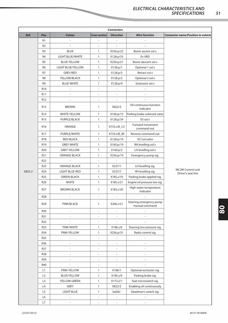
(23/07/2012) 80-01-M184EN
80
51ELECTRICAL CHARACTERISTICS AND
SPECIFICATIONS
Connectors
Ref. Pos. Colour Cross-section Direction Wire function Connector name/Position in vehicle
X825.2
R1 - - - -
MC2M Control unit
Driver's seat line
R2 - - - -
R3 BLUE 1 X256.p/22 Boom ascent sol.v
R4 LIGHT BLUE/WHITE 1 X128.p/33 Ev VRD
R5 BLUE-YELLOW 1 X256.p/21 Boom descent sol.v
R6 LIGHT BLUE/YELLOW 1 X128.p/1 Optional 1 sol.v
R7 GREY/RED 1 X128.p/3 Retract sol.v
R8 YELLOW/BLACK 1 X128.p/2 Optional 2 sol.v
R9 BLUE-WHITE 1 X128.p/9 Extension sol.v
R10 - - - -
R11 - - - -
R12 - - - -
R13 BROWN 1 X822/3Oil continuous function
indicator
R14 WHITE-YELLOW 1 X160.p/15 Parking brake solenoid valve
R15 PURPLE/BLACK 1 X128.p/34 VS sol.v
R16 ORANGE 1 X733.s/B_C2Forward movement
command out
R17 PURPLE/WHITE 1 X733.s/B_B5 Reverse command out
R18 RED-BLACK 1 X128.p/19 VCI sol.valve
R19 GREY-WHITE 1 X160.p/19 RH levelling sol.v
R20 GREY-YELLOW 1 X160.p/2 LH levelling sol.v
R21 ORANGE-BLACK 1 X256.p/19 Emergency pump sig.
R22 - - - -
R23 ORANGE-BLACK 1 X237/1 LH levelling sig.
R24 LIGHT BLUE-RED 1 X237/7 RH levelling sig.
R25 GREEN-BLACK 1 X185.s/10 Parking brake applied sig.
R26 WHITE 1 X185.s/21 Engine oil pressure low sig.
R27 BROWN-BLACK 1 X185.s/20High water temperature
indicator
R28 - - - -
R29 PINK/BLACK 1 X206.s/21Steering emergency pump
manual command
R30 - - - -
R31 - - - -
R32 - - - -
R33 PINK-WHITE 1 X186.s/6 Steering low pressure sig.
R34 PINK-YELLOW 1 X256.p/31 Radio control sig.
R35 - - - -
R36 - - - -
R37 - - - -
R38 - - - -
R39 - - - -
R40 - - - -
L1 PINK-YELLOW 1 X166/1 Optional exclusion sig.
L2 BLUE/YELLOW 1 X185.s/9 Parking brake sig.
L3 YELLOW-GREEN 1 X173.2/1 Seat microswitch sig.
L4 GREY 1 X822/2 Enabling oil continuously
L5 LIGHT BLUE 1 Sal28/- Deadman's switch sig.
L6 - - - -
L7 - - - -

(23/07/2012)80-01-M184EN
80
52ELECTRICAL CHARACTERISTICS AND SPECIFICATIONS
Connectors
Ref. Pos. Colour Cross-section Direction Wire function Connector name/Position in vehicle
X825.2
L8 - - - -
MC2M Control unit
Driver's seat line
L9 BROWN-YELLOW 1 X821/C Oil red. pow. sig.
L10 - - - -
L11 - - - -
L12 - - - -
L13 - - - -
L14 WHITE/GREEN 1 Sal38/- Emergency sig. (Ignition)
L15 - - - -
L16 - - - -
L17 LIGHT BLUE/RED 1 X167/7Optional sig. from
manipulator
L18 YELLOW-BROWN 1 X167/6Sig. ext./retract. by
manipulator
L19 - - - -
L20 - - - -
L21 LIGHT BLUE/BLACK 1 Sal40/- Directional Roller 1
L22 PINK-BLACK 1 Sal54/- Directional Roller 2
L23 GREY-YELLOW 1 X171.s/1 ARB forcing sig. IN
L24 PURPLE-BLACK 1 Sal55/- Forwards command
L25 GREEN-WHITE 1 Sal56/- Return command
L26 ORANGE-RED 1 X208/1Enable from boom int.
functions
L27 YELLOW 1 256.p/15 Platform mushroom sig.
L28 BLACK-PURPLE 1 X128.p/6NO boom closed
microswitch sig.
L29 ORANGE-WHITE 1 X186.s/7 Gear reset sig.
L30 BROWN/BLACK 1 X128.p/8NC boom closed microswitch
sig.
L31 YELLOW-GREEN 1 X160.p/12Gear engaged microswitch
sig.
L32 GREY 1 X128.p/31 Boom 1 angle sig.
L33 - - - -
L34 GREEN 1 X128.p/32 Boom 2 angle sig.
L35 - - - -
L36 GREEN-RED 1 X256.p/3 Spare
L37 YELLOW-BLACK 1 X256.p/1 Cab sig.
L38 YELLOW-GREEN 1 X256.p/18 Platform by-pass button
L39 BLUE-BLACK 1 X256.p/20 Descent pr.switch
L40 - - - -
X825.3
1 PURPLE 2.5 X731.s/10 PS +VP
MC2M Control unit
Driver's seat line
2 PURPLE 2.5 X731.s/1 PS +VP
3 PURPLE 2.5 X731.s/12 PS +VP
4 BLACK 2.5 Gnd5.2/- Gnd
X826.p
1 - - - -
CAN resistances counterfi gure
Driver's seat line
2 - - - -
3 - - - -
4 - - - -
5 - - - -
6 - - - -

(23/07/2012) 80-01-M184EN
80
53ELECTRICAL CHARACTERISTICS AND
SPECIFICATIONS
Connectors
Ref. Pos. Colour Cross-section Direction Wire function Connector name/Position in vehicle
X826.s
1 GREEN 0.35 X464/21 Can-L J1939
CAN BUS resistances
Driver's seat line
- GREEN 0.35 X825.1/26 Can-L J1939
2 GREEN 0.35 Sal52/- Can L Open 1
3 GREEN 0.35 X280.s/11 Can-L J1939
- GREEN 0.35 X464/21 Can-L J1939
4 WHITE 0.35 X825.1/7 Can-H J1939
- WHITE 0.35 X464/19 Can-H J1939
5 WHITE 0.35 Sal 53/- Can H Open 1
6 WHITE 0.35 X280.s/3 Can-H J1939
- WHITE 0.35 X464/19 Can-H J1939
X851
1 PINK ORANGE GREY 0.32 Sal23/- Shield
Rear axle load cell
Rear line
2 RED 0.32 X128.s/24 ARB cell PS
3 BLACK 0.32 X128.s/28 ARB cell Gnd
4 WHITE 0.2 X128.s/26 Can H Open
5 BLUE 0.2 X128.s/27 Can L Open
X899.11 WHITE-GREEN 1 X825.1/14 Steering emergency pump Emergency pump buzzer
Driver's seat line- WHITE-GREEN 1 X256.p/27 Steering emergency pump
X899.2 1 BLACK 1 X478.2/1 GndEmergency pump buzzer
Driver's seat line
X900
A1 LIGHT BLUE-YELLOW 1.5 X910.s/1 EVB Gripper
Independent relays control unit
Radio gripper platform line
A2 YELLOW-GREEN 1.5 X910.s/4 EVE Gripper
A3 - - - -
A4 ORANGE-BLACK 0.5 X903/1 EVD Gripper sig.
A5 BLACK 0.5 Sa3/- Ground
A6 BLACK 0.5 Sa3/- Ground
A7 ORANGE-WHITE 0.5 X902/8 Gripper EVC sig.
A8 BLUE-WHITE 1.5 X910.s/2 EVC Gripper
B1 - - - -
B2 GREY 1.5 X900/C6 +15 Jumper
B3 BLACK 0.5 Sa3/- Ground
B4 ORANGE-RED 0.5 X903/7 EVE Gripper sig.
B5 BLACK 0.5 Sa3/- Ground
B6 ORANGE-LIGHT BLUE 0.5 X902/1 Gripper EVB sig.
B7 - - - -
B8 - - - -
C1 YELLOW-BLACK 1.5 X910.s/3 Gripper EVD
C2 GREY 1.5 X900/C4 +15 Jumper
C3 GREY 1.5 Sa1/- +15 gripper SV
C4 GREY 1.5 X900/C2 +15 Jumper
C5 GREY 1.5 X900/C8 +15 Jumper
C6 GREY 1.5 X900/B2 +15 Jumper
C7 - - - -
C8 GREY 1.5 X900/C5 +15 Jumper

(23/07/2012)80-01-M184EN
80
54ELECTRICAL CHARACTERISTICS AND SPECIFICATIONS
Connectors
Ref. Pos. Colour Cross-section Direction Wire function Connector name/Position in vehicle
X901.1
1 GREY-RED 1.5 X914.2/24 Radio mushroom In
Cab/remote/radio selection switch
Radio gripper platform line
2 PINK-YELLOW 1 X256.s/31 Radio control sig.
- PINK-YELLOW 1 X914.1/1 +15 Radio
3 - - - -
4 - - - -
5 WHITE-BLACK 1.5 X950.s/8 Mushrooms switching
- WHITE-BLACK 1.5 X901.2/2 2 Jumper
6 PURPLE-YELLOW 1 X901.2/1 Jumper
- PURPLE-YELLOW 1 X950.s/5 Cab sig.
7 WHITE 1.5 Sa6/- Mushroom out
- WHITE 1.5 X901.3/2 2 Jumper
8 YELLOW-BLACK 1 X256.s/1 Cab sig.
- YELLOW-BLACK 1 X901.3/1 Jumper
9 GREY/BLACK 1 Sa1/- Radio selector PS
10 BLACK 1 X902/10 Ground
X901.21 PURPLE-YELLOW 1 X901.1/6 Jumper 1 Jumper
Radio gripper platform line2 WHITE-BLACK 1.5 X901.1/5 2 Jumper
X901.31 YELLOW-BLACK 1 X901.1/8 Jumper 2 Jumper
Radio gripper platform line2 WHITE 1.5 X901.1/7 2 Jumper
X902
1 ORANGE-LIGHT BLUE 0.5 X914.2/21 Gripper EVB sig.
Gripper 1 switch without block
Radio gripper platform line
- ORANGE-LIGHT BLUE 0.5 X900/B6 Gripper EVB sig.
2 GREY/BLACK 1 X903/3 +15 Int. gripper 2
3 GREY/BLACK 1 X902/9 Switches lighting
4 - - - -
5 - - - -
6 GREY 1 X902/7 +15 Jumper
7 GREY 1 X902/6 +15 Jumper
8 ORANGE-WHITE 0.5 X900/A7 Gripper EVC sig.
- ORANGE-WHITE 0.5 X914.2/20 Gripper EVC sig.
9 GREY/BLACK 1 X902/3 Ill. switches
- GREY/BLACK 1 Sa1/- +15 Platform
10 BLACK 1 X901.1/10 Ground
- BLACK 1 X903/10 Ground
X903
1 ORANGE-BLACK 0.5 X900/A4 EVD Gripper sig.
Gripper 2 switch with block
Radio gripper platform line
- ORANGE-BLACK 0.5 X914.2/22 EVD Gripper sig.
2 - - - -
3 GREY/BLACK 1 X903/9 +15 Jumper
- GREY/BLACK 1 X902/2 +15 gripper switch 2
4 - - - -
5 - - - -
6 - - - -
7 ORANGE-RED 0.5 X914.2/19 Gripper EVE sig.
- ORANGE-RED 0.5 X900/B4 EVE Gripper sig.
8 - - - -
9 GREY/BLACK 1 X903/3 +15 Jumper
10 BLACK 1 X902/10 Ground
- BLACK 1 Sa7/- Ground
X9041 YELLOW-BLACK 1 X256.s/25 Oil Switch sol.valve Oil switch sol.valve
Radio gripper platform line2 BLACK 1 Sa7/- Ground

(23/07/2012) 80-01-M184EN
80
55ELECTRICAL CHARACTERISTICS AND
SPECIFICATIONS
Connectors
Ref. Pos. Colour Cross-section Direction Wire function Connector name/Position in vehicle
X905.p1 - - - - Cap
Radio gripper platform line2 - - - -
X905.s1 GREY-BLACK 1 X256.s/24 Slewing 1 sol.v Slewing 1 solenoid valve
Radio gripper platform line2 BLACK 1 Sa7/- Ground
X906.p1 - - - - Cap
Radio gripper platform line2 - - - -
X906.s1 GREY-RED 1 X256.s/23 Slewing 2 sol.v Slewing 2 solenoid valve
Radio gripper platform line2 BLACK 1 Sa7/- Ground
X9071 BLUE 1 X256.s/22 Up SV Up solenoid valve
Radio gripper platform line2 BLACK 1 Sa7/- Ground
X9081 BLUE-YELLOW 1 X256.s/21 Down SV Down solenoid valve
Radio gripper platform line2 BLACK 1 Sa7/- Ground
X909
1 YELLOW-RED 1 X955.p/1 + VE
Descent pressure switch
Descent pressure switch line
2 - - - -
3 BLUE-BLACK 1 X955.p/2 Descent press. sig.
T - - - -
X910.p
1 - - - -
Cap
Radio gripper platform line
2 - - - -
3 - - - -
4 - - - -
5 - - - -
6 - - - -
7 - - - -
8 - - - -
X910.p
1 LIGHT BLUE-YELLOW 1.5 X959.1/1 Gripper SVB
Connector for platform/gripper line
Gripper arm extension
2 BLUE-WHITE 1.5 X959.2/1 Gripper SVC
3 YELLOW-BLACK 1.5 X959.3/1 Gripper SVD
4 YELLOW-GREEN 1.5 X959.4/1 Gripper SVE
5 BLACK 1.5 X959.5/1 Ground
6 - - - -
7 - - - -
8 - - - -
X910.s
1 LIGHT BLUE-YELLOW 1.5 X900/A1 Gripper SVB
Gripper connector
Radio gripper platform line
2 BLUE-WHITE 1.5 X900/A8 Gripper SVC
3 YELLOW-BLACK 1.5 X900/C1 Gripper SVD
4 YELLOW-GREEN 1.5 X900/A2 Gripper SVE
5 BLACK 1.5 Sa5/- Gripper ground
6 - - - -
7 - - - -
8 - - - -
X911
A WHITE 0.35 Sa4/- Can HCAN line end
Radio gripper platform lineB GREEN 0.35 Sa2/- Can L
C
X911.p
A - - - -Cap
Radio gripper platform lineB - - - -
C - - - -
X913.1 - GREY-WHITE 1.5 X950.p/1 Mushroom InPlatform-cab selection key
Key-button extension
X913.2 - WHITE-BLACK 1.5 X950.p/8 Mushroom switchingPlatform-cab selection key
Key-button extension

(23/07/2012)80-01-M184EN
80
56ELECTRICAL CHARACTERISTICS AND SPECIFICATIONS
Connectors
Ref. Pos. Colour Cross-section Direction Wire function Connector name/Position in vehicle
X913.3 - YELLOW-RED 1 X951.1/- + VEPlatform-cab selection key
Key-button extension
X913.4 - PURPLE-YELLOW 1 X950.p/5 Cab sig.Platform-cab selection key
Key-button extension
X914.1
1 PINK-YELLOW 1 X901.1/2 +15 Radio
Radio 1-16
Radio gripper platform line
2 - - - -
3 - - - -
4 - - - -
5 - - - -
6 - - - -
7 - - - -
8 - - - -
9 - - - -
10 - - - -
11 - - - -
12 - - - -
13 - - - -
14 - - - -
15 WHITE 0.35 Sa4/- CAN H
16 GREEN 0.35 Sa2/- CAN L
X914.2
17 - - - -
Radio 17-32
Radio gripper platform line
18 - - - -
19 ORANGE-RED 0.5 X903/7 Gripper SVE sig.
20 ORANGE-WHITE 0.5 X902/8 Gripper SVC sig.
21 ORANGE-LIGHT BLUE 0.5 X902/1 Gripper SVB sig.
22 ORANGE-BLACK 0.5 X903/1 Gripper SVD sig.
23 - - - -
24 GREY-RED 1.5 X901.1/1 Radio mushroom In
25 WHITE 1.5 Sa6/- Radio mushroom out
26 WHITE-YELLOW 1 X256.s/14 Accelerate sig.
27 LIGHT BLUE/YELLOW 1 X256.s/13 Decelerate sig.
28 LIGHT BLUE-YELLOW 1 X916.s/EStart-up from platform/
remote
- LIGHT BLUE-YELLOW 1 X256.s/8 Start up by radio control
29 - - - -
30 LIGHT BLUE-WHITE 1 X256.s/9 Warning siren
31 - - - -
32 BLACK 1 Sa7/- Ground
X915
1 WHITE/GREEN 1 X256.s/12 1450 rpm speed sig.
Platform controlled speed switch
Radio gripper platform line
2 - - - -
3 - - - -
4 - - - -
5 BLACK 1 Sa7/- Ground
- BLACK 1 X915/10 1450 rpm speed sig.
6 - - - -
7 - - - -
8 - - - -
9 GREY/BLACK 1 X953/9 +15
10 BLACK 1 X953/10 Ground
- BLACK 1 X915/5 1450 rpm speed sig.

(23/07/2012) 80-01-M184EN
80
57ELECTRICAL CHARACTERISTICS AND
SPECIFICATIONS
Connectors
Ref. Pos. Colour Cross-section Direction Wire function Connector name/Position in vehicle
X916.p
A - - - -
Cap
Radio gripper platform line
B - - - -
C - - - -
D - - - -
E - - - -
F - - - -
G - - - -
H - - - -
J - - - -
K - - - -
L - - - -
M - - - -
N - - - -
P - - - -
X916.p
A GREY 1.5 X958.s/1 +15 Platform
Connector for Platform/gripper line
Winder extension
B YELLOW 1.5 X958.s/2 Mushroom Out
C WHITE 0.35 X958.s/3 CAN H
D GREEN 0.35 X958.s/4 CAN H
E LIGHT BLUE-YELLOW 1.5 X958.s/5 Start-up from platform
F GREY-WHITE 1.5 X958.s/6 Mushroom enabling
G BLACK 2 X958.s/7 Ground
H GREEN-RED 1.5 X958.s/8 Spare
J - - - -
K - - - -
L - - - -
M - - - -
N - - - -
P - - - -
X916.s
A GREY 1.5 Sa1/- +15 Platform
Platform/remote connector
Radio gripper platform line
B YELLOW 1.5 X956.s/2 Platform Mushroom Out
C WHITE 0.35 Sa4/- Can H
D GREEN 0.35 Sa2/- Can L
E LIGHT BLUE-YELLOW 1 X914.2/28 Start-up from platform/remote
F GREY-WHITE 1.5 Sa8/- Platform mushroom enabling
G BLACK 2 Sa5/- Ground
H GREEN-RED 1.5 X256.s/3 Spare
J - - - -
K - - - -
L - - - -
M - - - -
N - - - -
P - - - -
X950.p
1 WHITE 1 X950.p/8 1 Jumper
Cap
Radio gripper platform line
2 - - - -
3 ORANGE 1 X950.p/5 2 Jumper
4 - - - -
5 ORANGE 1 X950.p/3 2 Jumper
6 - - - -
7 - - - -
8 WHITE 1 X950.p/1 1 Jumper

(23/07/2012)80-01-M184EN
80
58ELECTRICAL CHARACTERISTICS AND SPECIFICATIONS
Connectors
Ref. Pos. Colour Cross-section Direction Wire function Connector name/Position in vehicle
X950.p
1 GREY-WHITE 1.5 X913.1/- Mushroom In
Connector for Platform/gripper line
Key-button extension
2 - - - -
3 YELLOW-RED 1 X951.1/- + VE
4 - - - -
5 PURPLE-YELLOW 1 X913.4/- Cab sig.
6 YELLOW-GREEN 1 X951.2/- Reset sig.
7 - - - -
8 WHITE-BLACK 1.5 X913.2/- Mushroom switching
X950.s
1 GREY-WHITE 1.5 Sa8/- Mushroom In
Key/Button connector
Radio gripper platform line
2 - - - -
3 YELLOW-RED 1 Sa9/- + VE
4 - - - -
5 PURPLE-YELLOW 1 X901.1/6 Cab sig.
6 YELLOW-GREEN 1 X256.s/18 Reset sig.
7 - - - -
8 WHITE-BLACK 1.5 X901.1/5 Mushroom switching
X951.1- YELLOW-RED 1 X950.p/3 + VE Reset button
Key-button extension- YELLOW-RED 1 X913.3/- + VE
X951.2 - YELLOW-GREEN 1 X950.p/6 Reset sig.Reset button
Key-button extension
X952
1 BLUE-BLACK 1 Sal25/- Gnd
Boom angle sensor
Rear line
2 GREY-GREEN 1 Sal24/- Boom sensor PS
3 GREY 1 X128.s/31 Boom 1 angle sig.
4 BLUE-BLACK 1 Sal25/- Gnd
5 GREY-GREEN 1 Sal24/- Boom sensor PS
6 GREEN 1 X128.s/32 Boom 2 angle sig.
X953
1 GREY-GREEN 1 X954/1 Emergency pump
Emergency pump switch
Radio gripper platform line
- GREY-GREEN 1 X957/87 Emergency pump relay
2 - - - -
3 - - - -
4 - - - -
5 GREY/BLACK 1 X957/30 +15 Pump relay
- GREY/BLACK 1 X953/9 +15 Jumper
6 - - - -
7 - - - -
8 - - - -
9 GREY/BLACK 1 X915/9 +15
- GREY/BLACK 1 X953/5 +15 Jumper
10 BLACK 1 X915/10 Ground
BLACK 1 Sa7/- Ground
X9541 GREY-GREEN 1 X953/1 Emergency pump OPT emergency pump
Radio gripper platform line2 BLACK 1 Sa7/- Ground
X954.p1 - - - - Cap
Radio gripper platform line2 - - - -
X9551 RED-BLACK 1 X128.s/19 VCI sol.valve VCI solenoid valve
Rear line2 BLACK 1 Gnd2/- Gnd
X955.p1 YELLOW-RED 1 X909/1 + VE Connector
Descent pressure switch line2 BLUE-BLACK 1 X909/3 Descent press. sig.
X955.s1 YELLOW-RED 1 Sa9/- +VE Descent pr. switch extension
Radio gripper platform line2 BLUE-BLACK 1 X256.s/20 Descent press. sig.

(23/07/2012) 80-01-M184EN
80
59ELECTRICAL CHARACTERISTICS AND
SPECIFICATIONS
Connectors
Ref. Pos. Colour Cross-section Direction Wire function Connector name/Position in vehicle
X956.p1 - - - - Diode connector
Radio gripper platform line2 - - - -
X956.s
1 WHITE 1.5 Sa6/- Mushroom Out
6A diode connector
Radio gripper platform line
2 YELLOW 1.5 X916.s/B Platform Mushroom Out
- YELLOW 1 X256.s/15MC2-M platform mushroom
sig.
X957
85 BLACK 1 Sa3/- Ground
Emergency pump relay from
platform
Radio gripper platform line
86 ORANGE-BLACK 1 X256.s/19 Em. pump sig. from platform
30 GREY/BLACK 1 Sa1/- +15 Platform
- GREY/BLACK 1 X953/5 +15 Pump relay
87 GREY-GREEN 1 X953/1 Emergency pump relay
87a - - - -
X958.s
1 GREY 1.5 X916.p/A +15 Platform
Winder connector
Winder extension
2 YELLOW 1.5 X916.p/B Mushroom Out
3 WHITE 0.35 X916.p/C CAN H
4 GREEN 0.35 X916.p/D CAN H
5 LIGHT BLUE-YELLOW 1.5 X916.p/E Start-up from platform
6 GREY-WHITE 1.5 X916.p/F Mushroom enabling
7 BLACK 2 X916.p/G Ground
8 GREEN-RED 1.5 X916.p/H Spare
X959.1 1 LIGHT BLUE-YELLOW 1.5 X910.p/1 Gripper SVBGripper SVB
Gripper arm extension
X959.2 1 BLUE-WHITE 1.5 X910.p/2 Gripper SVCGripper SVC
Gripper arm extension
X959.3 1 YELLOW-BLACK 1.5 X910.p/3 Gripper SVDGripper SVD
Gripper arm extension
X959.4 1 YELLOW-GREEN 1.5 X910.p/4 Gripper SVEGripper SVE
Gripper arm extension
X959.5 1 BLACK 1.5 X910.p/5 GroundGripper ground
Gripper arm extension
XB1
1 RED 1.5 XC1/1 +15 Platform
Boom winder
Platform arm extension
2 YELLOW 1.5 XC1/9 Platform mushroom Out
3 WHITE 0.5 XC1/2 CAN H
4 BROWN 0.5 XC1/3 CAN L
5 PINK 1.5 XC1/10 Start up from platform
6 GREY 1.5 XC1/8 Platform mushroom Out
7 BLACK 1 XB1/T1 Ground
- BLUE 1.5 XC1/7 Ground
8 GREEN 1.5 XC1/15 Spare
9 - - - -
10 - - - -
11 - - - -
12 - - - -
13 - - - -
14 - - - -
15 - - - -
16 - - - -
T1 BLACK 1 XB1/7 Ground
T2 - - - -

(23/07/2012)80-01-M184EN
80
60ELECTRICAL CHARACTERISTICS AND SPECIFICATIONS
Connectors
Ref. Pos. Colour Cross-section Direction Wire function Connector name/Position in vehicle
XC1
1 RED 1 XC1/20 +15 Platform
Platform connector
Platform arm extension
- RED 1.5 XB1/1 +15 Platform
2 WHITE 0.5 XB1/3 CAN H
3 BROWN 0.5 XB1/4 CAN L
4 - - - -
5 - - - -
6 - - - -
7 BLACK 1 XC1/T1 Ground
- BLUE 1.5 XB1/7 Ground
8 GREY 1.5 XB1/6 Platform mushroom Out
9 YELLOW 1.5 XB1/2 Platform mushroom Out
10 PINK 1.5 XB1/5 Start up from platform
11 - - - -
12 - - - -
13 - - - -
14 - - - -
15 GREEN 1.5 XB1/8 Spare
16 - - - -
17 - - - -
18 - - - -
19 - - - -
20 RED 1 XC1/1 +15 Platform
21 - - - -
22 - - - -
23 - - - -
24 - - - -
T1 BLACK 1 XC1/7 Ground
- WHITE-BLACK 0.5 Sa1/- Shield
T2 - - - -