Embed Size (px)
Citation preview
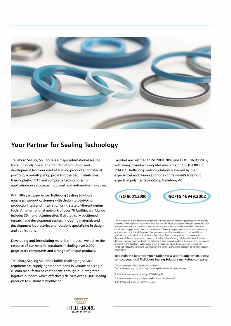
Your Partner for Sealing Technology
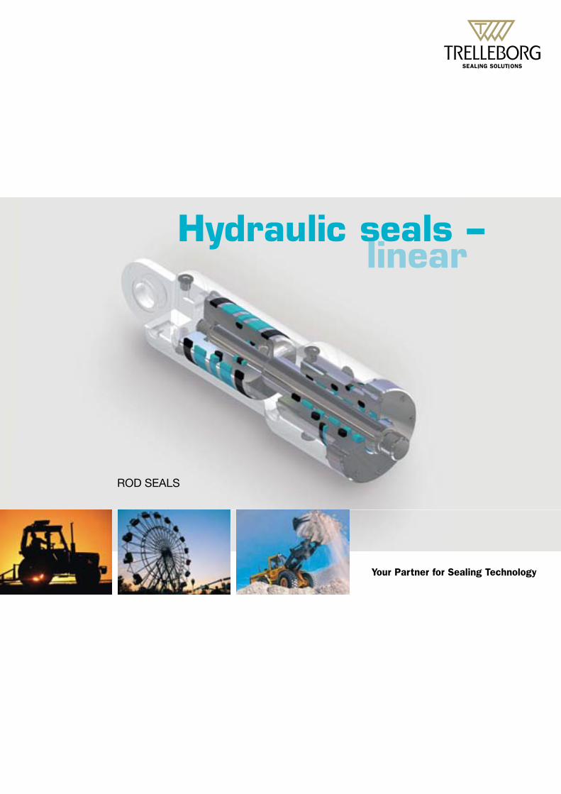
Hydraulic seals –linear
ROD SEALS
Your Partner for Sealing Technology
Trelleborg Sealing Solutions is a major international sealing
force, uniquely placed to offer dedicated design and
development from our market leading product and material
portfolio; a one-stop shop providing the best in elastomer,
thermoplastic, PTFE and composite technologies for
applications in aerospace, industrial, and automotive industries.
With 50-years experience, Trelleborg Sealing Solutions
engineers support customers with design, prototyping,
production, test and installation using state-of-the-art design
tools. An international network of over 70 facilities worldwide
research and development centers, including materials and
development laboratories and locations specializing in design
and applications.
Developing and formulating materials in-house, we utilize the
resource of our material database, including over 2,000
proprietary compounds and a range of unique products.
Trelleborg Sealing Solutions fulfills challenging service
requirements, supplying standard parts in volume or a single
custom-manufactured component, through our integrated
logistical support, which effectively delivers over 40,000 sealing
products to customers worldwide.
Facilities are certified to ISO 9001:2000 and ISO/TS 16949:2002,
with many manufacturing sites also working to QS9000 and
VDA 6.1. Trelleborg Sealing Solutions is backed by the
experiences and resources of one of the world's foremost
experts in polymer technology, Trelleborg AB.
The information in this brochure is intended to be for general reference purposes only and is notintended to be a specific recommendation for any individual application. The application limits forpressure, temperature, speed and media given are maximum values determined in laboratoryconditions. In application, due to the interaction of operating parameters, maximum values maynot be achieved. It is vital therefore, that customers satisfy themselves as to the suitability ofproduct and material for each of their individual applications. Any reliance on information istherefore at the user's own risk. In no event will Trelleborg Sealing Solutions be liable for any loss,damage, claim or expense directly or indirectly arising or resulting from the use of any informationprovided in this brochure. While every effort is made to ensure the accuracy of informationcontained herewith, Trelleborg Sealing Solutions cannot warrant the accuracy or completeness ofinformation.
To obtain the best recommendation for a specific application, pleasecontact your local Trelleborg Sealing Solutions marketing company.
This edition supersedes all previous brochures.This brochure or any part of it may not be reproduced without permission.
® All trademarks are the property of Trelleborg AB.
The turquoise colour is a registered trademark of Trelleborg AB.
© Trelleborg AB, 2007. All rights reserved.
includes 30 manufacturing sites, 8 strategically positioned
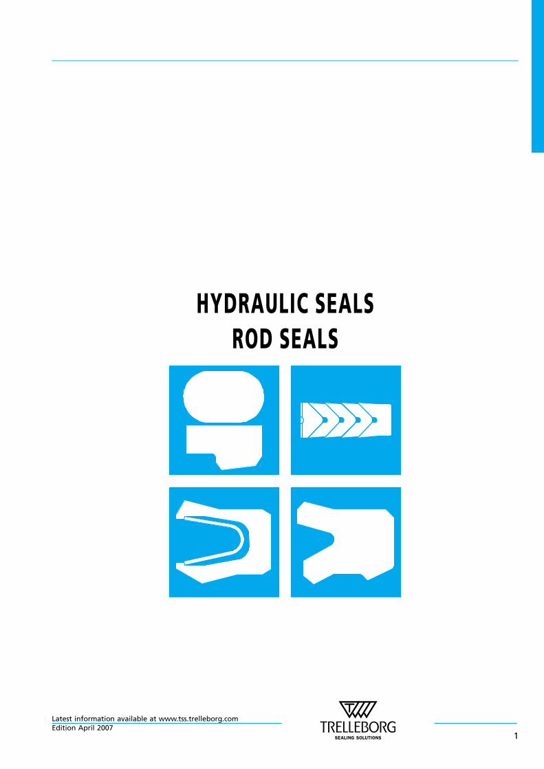
HYDRAULIC SEALSROD SEALS
Latest information available at www.tss.trelleborg.comEdition April 2007
1

Latest information available at www.tss.trelleborg.com
2Edition April 2007
Contents
Choice of the Sealing Element . . . . . . . . . . . . . . . . . . . . . . . . . . . . . . . . . . . . . . . . . . . . . . . . . . . . . . . . . . . . . . . 4
Design Instructions . . . . . . . . . . . . . . . . . . . . . . . . . . . . . . . . . . . . . . . . . . . . . . . . . . . . . . . . . . . . . . . . . . . . . . . . . . 8
Installation Instructions . . . . . . . . . . . . . . . . . . . . . . . . . . . . . . . . . . . . . . . . . . . . . . . . . . . . . . . . . . . . . . . . . . . . 10
Quality Criteria . . . . . . . . . . . . . . . . . . . . . . . . . . . . . . . . . . . . . . . . . . . . . . . . . . . . . . . . . . . . . . . . . . . . . . . . . . . . 14
Storage Instructions . . . . . . . . . . . . . . . . . . . . . . . . . . . . . . . . . . . . . . . . . . . . . . . . . . . . . . . . . . . . . . . . . . . . . . . 14
Turcon® Stepseal® 2K . . . . . . . . . . . . . . . . . . . . . . . . . . . . . . . . . . . . . . . . . . . . . . . . . . . . . . . . . . . . . . . . . . . . . . 17
Zurcon® Rimseal . . . . . . . . . . . . . . . . . . . . . . . . . . . . . . . . . . . . . . . . . . . . . . . . . . . . . . . . . . . . . . . . . . . . . . . . . . . 35
POLYPAC® - Veepac CH/G5 . . . . . . . . . . . . . . . . . . . . . . . . . . . . . . . . . . . . . . . . . . . . . . . . . . . . . . . . . . . . . . . . . 47
POLYPAC® - Selemaster SM . . . . . . . . . . . . . . . . . . . . . . . . . . . . . . . . . . . . . . . . . . . . . . . . . . . . . . . . . . . . . . . . . 53
POLYPAC® - Balsele . . . . . . . . . . . . . . . . . . . . . . . . . . . . . . . . . . . . . . . . . . . . . . . . . . . . . . . . . . . . . . . . . . . . . . . . 61
Zurcon® L-Cup®. . . . . . . . . . . . . . . . . . . . . . . . . . . . . . . . . . . . . . . . . . . . . . . . . . . . . . . . . . . . . . . . . . . . . . . . . . . . 81
Zurcon® U-Cup, Type RU0 . . . . . . . . . . . . . . . . . . . . . . . . . . . . . . . . . . . . . . . . . . . . . . . . . . . . . . . . . . . . . . . . . . 91
Zurcon® U-Cup, Type RU2 . . . . . . . . . . . . . . . . . . . . . . . . . . . . . . . . . . . . . . . . . . . . . . . . . . . . . . . . . . . . . . . . . . 97
Zurcon® U-Cup, Type RU3 . . . . . . . . . . . . . . . . . . . . . . . . . . . . . . . . . . . . . . . . . . . . . . . . . . . . . . . . . . . . . . . . . 103
Zurcon® U-Cup, Type RU6 . . . . . . . . . . . . . . . . . . . . . . . . . . . . . . . . . . . . . . . . . . . . . . . . . . . . . . . . . . . . . . . . . 109
Turcon® Variseal® M2 . . . . . . . . . . . . . . . . . . . . . . . . . . . . . . . . . . . . . . . . . . . . . . . . . . . . . . . . . . . . . . . . . . . . . 117
Turcon® Glyd Ring®. . . . . . . . . . . . . . . . . . . . . . . . . . . . . . . . . . . . . . . . . . . . . . . . . . . . . . . . . . . . . . . . . . . . . . . 123
Turcon® Glyd Ring® T . . . . . . . . . . . . . . . . . . . . . . . . . . . . . . . . . . . . . . . . . . . . . . . . . . . . . . . . . . . . . . . . . . . . . 137
Turcon® Double Delta® . . . . . . . . . . . . . . . . . . . . . . . . . . . . . . . . . . . . . . . . . . . . . . . . . . . . . . . . . . . . . . . . . . . . 151
Non Standard Seals . . . . . . . . . . . . . . . . . . . . . . . . . . . . . . . . . . . . . . . . . . . . . . . . . . . . . . . . . . . . . . . . . . . . . . . 159
Rod Seals
Latest information available at www.tss.trelleborg.comEdition April 2007
3
n Choice of the Sealing Element
Sealing elements have a decisive influence on the design,function and service life of hydraulic and pneumaticcylinders and systems.
This applies equally to the piston rod seals where leaktightness, resistance to wear and gap extrusion, resistanceto process media, resistance to high and low temperatures,low friction, compact form and simple installation aredemanded in order to meet the requirements of industryfor a functional sealing solution.
The significance of these parameters and their limits isgenerally dependent on the requirements of the specificapplication. Trelleborg Sealing Solutions has thereforedeveloped a complete range of seals which, due to theiroptimized geometries and designs and the use of high-quality materials such as Turcon® and Zurcon®, satisfy thetechnical and economic demands of the industry in full.
In order to be in a position to select the most appropriateseal type and material, it is necessary to first define all thedesired functional parameters. Table I can then be used tomake an initial selection of seals and materials according tothe specific requirements of the application.
The second column of the table contains the number of thepage on which further general information together withspecific design and installation instructions on theparticular seal type and materials (or materialcombinations with multi-element seals, e.g. Turcon®
Stepseal® 2K) can be found.
Furthermore on page 9, attention is drawn to the qualityof the mating surface. We recommend that the limitsspecified there be observed, as they have a decisiveinfluence on the functionality and service life of thesystem.
The final choice of seal type and material must also takeaccount of the detailed information on the seal elements.
Please do not hesitate to contact our Technical Departmentfor further information on specific applications and specialtechnical questions.
This Catalogue is a compilation of the preferred productranges of Trelleborg Sealing Solutions, Sealing Parts andPOLYPAC. All similar products are technically equivalentbut availability and pricing may vary. For furtherinformation please contact your local Trelleborg SealingSolutions company.
Note on Ordering
All multi-element standard rod seals, e.g. Turcon® Stepseal®
2K, are generally supplied as complete seal sets. The supplyincludes the seal and matching elastomer energizingelements. The O—Ring does not have to be orderedseparately. It is also possible to use other O—Ring materialsfrom our O—Ring catalogue. In this case, please order theseal ring and O—Ring separately.
When ordering the seal ring separately, it is then notnecessary to mention the “O—Ring material code“ in the TSSArticle No. shown in the ordering examples.
Older designs of seals no longer contained in this cataloguenaturally continue to be available (see chapter NonStandard Seals). For all new applications, however, werecommend the use of the seal types and preferred sizes(ISO series, wherever possible) listed in this catalogue.
Other combinations of Turcon® materials and specialdesigns can be developed and supplied for specialapplications in all intermediate sizes up to 2.600 mmdiameter, provided there is sufficient demand.
The sizes contained in this catalogue are mostly availablefrom stock or can be supplied at short notice. We reservethe right to modify our supply programme.
Rod Seals
Latest information available at www.tss.trelleborg.com
4Edition April 2007
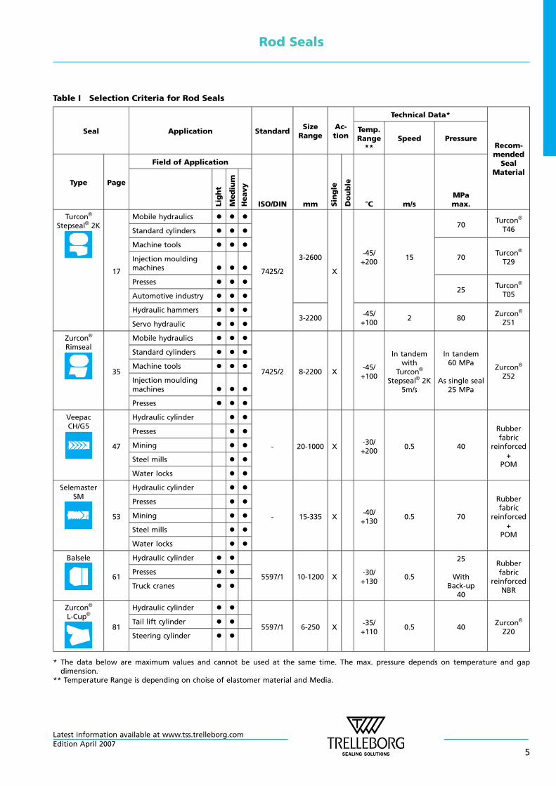
Table I Selection Criteria for Rod Seals
Seal Application StandardSizeRange
Ac-tion
Technical Data*
Recom-mendedSeal
Material
Temp.Range**
Speed Pressure
Type Page
Field of Application
ISO/DIN mm Single
Double
°C m/sMPamax.L
ight
Medium
Heavy
Turcon®
Stepseal® 2K
17
Mobile hydraulics l l l
7425/2
3-2600
X
-45/+200
15
70Turcon®
T46Standard cylinders l l l
Machine tools l l l
70Turcon®
T29Injection mouldingmachines l l l
Presses l l l25
Turcon®
T05Automotive industry l l l
Hydraulic hammers l l l3-2200
-45/+100
2 80Zurcon®
Z51Servo hydraulic l l l
Zurcon®
Rimseal
35
Mobile hydraulics l l l
7425/2 8-2200 X-45/+100
In tandemwith
Turcon®
Stepseal® 2K5m/s
In tandem60 MPa
As single seal25 MPa
Zurcon®
Z52
Standard cylinders l l l
Machine tools l l l
Injection mouldingmachines l l l
Presses l l l
VeepacCH/G5
47
Hydraulic cylinder l l
- 20-1000 X-30/+200
0.5 40
Rubberfabric
reinforced+
POM
Presses l l
Mining l l
Steel mills l l
Water locks l l
SelemasterSM
53
Hydraulic cylinder l l
- 15-335 X-40/+130
0.5 70
Rubberfabric
reinforced+
POM
Presses l l
Mining l l
Steel mills l l
Water locks l l
Balsele
61
Hydraulic cylinder l l
5597/1 10-1200 X-30/+130
0.5
25
WithBack-up
40
Rubberfabric
reinforcedNBR
Presses l l
Truck cranes l l
Zurcon®
L-Cup®
81
Hydraulic cylinder l l
5597/1 6-250 X-35/+110
0.5 40Zurcon®
Z20
Tail lift cylinder l l
Steering cylinder l l
* The data below are maximum values and cannot be used at the same time. The max. pressure depends on temperature and gapdimension.
** Temperature Range is depending on choise of elastomer material and Media.
Rod Seals
Latest information available at www.tss.trelleborg.comEdition April 2007
5
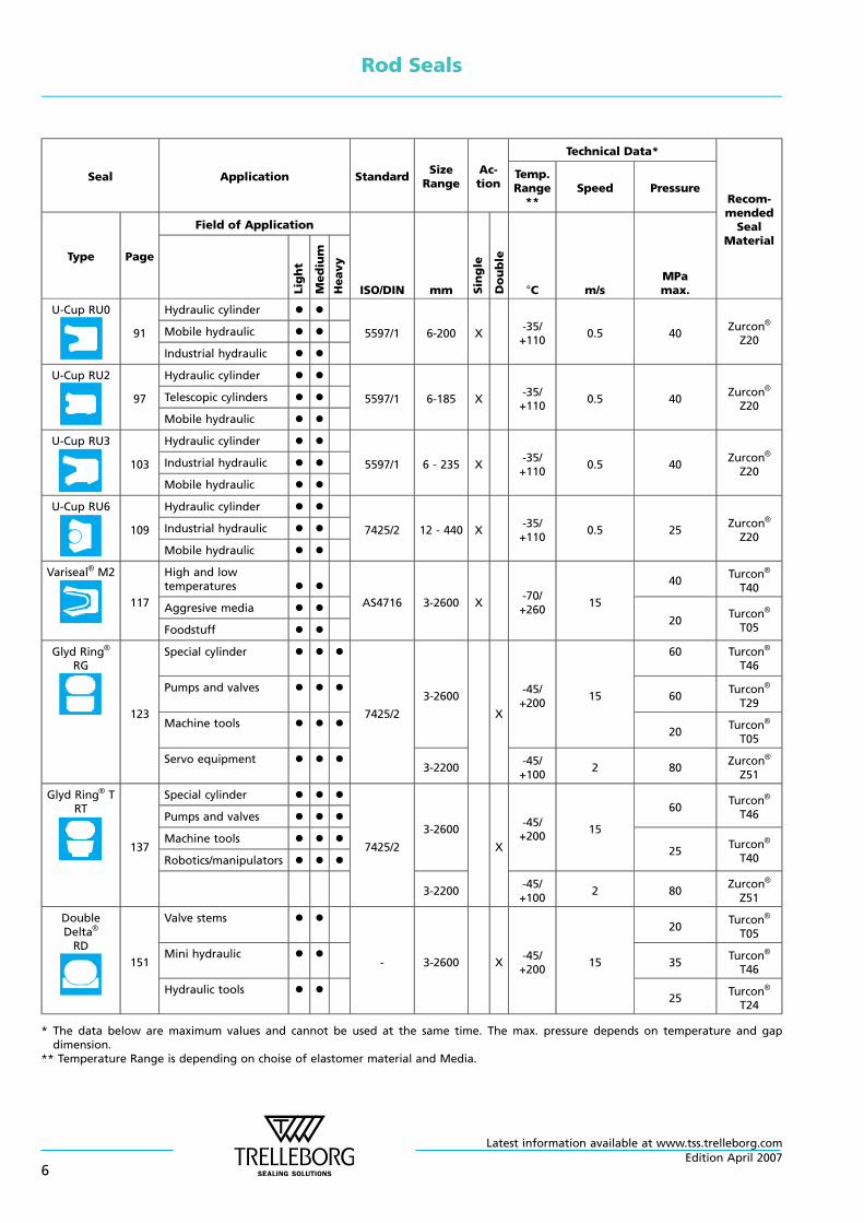
Seal Application StandardSizeRange
Ac-tion
Technical Data*
Recom-mendedSeal
Material
Temp.Range**
Speed Pressure
Type Page
Field of Application
ISO/DIN mm Single
Double
°C m/sMPamax.L
ight
Medium
Heavy
U-Cup RU0
91
Hydraulic cylinder l l
5597/1 6-200 X-35/+110
0.5 40Zurcon®
Z20Mobile hydraulic l l
Industrial hydraulic l l
U-Cup RU2
97
Hydraulic cylinder l l
5597/1 6-185 X-35/+110
0.5 40Zurcon®
Z20Telescopic cylinders l l
Mobile hydraulic l l
U-Cup RU3
103
Hydraulic cylinder l l
5597/1 6 - 235 X-35/+110
0.5 40Zurcon®
Z20Industrial hydraulic l l
Mobile hydraulic l l
U-Cup RU6
109
Hydraulic cylinder l l
7425/2 12 - 440 X-35/+110
0.5 25Zurcon®
Z20Industrial hydraulic l l
Mobile hydraulic l l
Variseal® M2
117
High and lowtemperatures l l
AS4716 3-2600 X-70/+260
15
40Turcon®
T40
Aggresive media l l20
Turcon®
T05Foodstuff l l
Glyd Ring®
RG
123
Special cylinder l l l
7425/2
3-2600
X
-45/+200
15
60 Turcon®
T46
Pumps and valves l l l60
Turcon®
T29
Machine tools l l l20
Turcon®
T05
Servo equipment l l l3-2200
-45/+100
2 80Zurcon®
Z51
Glyd Ring® TRT
137
Special cylinder l l l
7425/2
3-2600
X
-45/+200
15
60Turcon®
T46Pumps and valves l l l
Machine tools l l l25
Turcon®
T40Robotics/manipulators l l l
3-2200-45/+100
2 80Zurcon®
Z51
DoubleDelta®
RD
151
Valve stems l l
- 3-2600 X-45/+200
15
20Turcon®
T05
Mini hydraulic l l35
Turcon®
T46
Hydraulic tools l l25
Turcon®
T24
* The data below are maximum values and cannot be used at the same time. The max. pressure depends on temperature and gapdimension.
** Temperature Range is depending on choise of elastomer material and Media.
Rod Seals
Latest information available at www.tss.trelleborg.com
6Edition April 2007
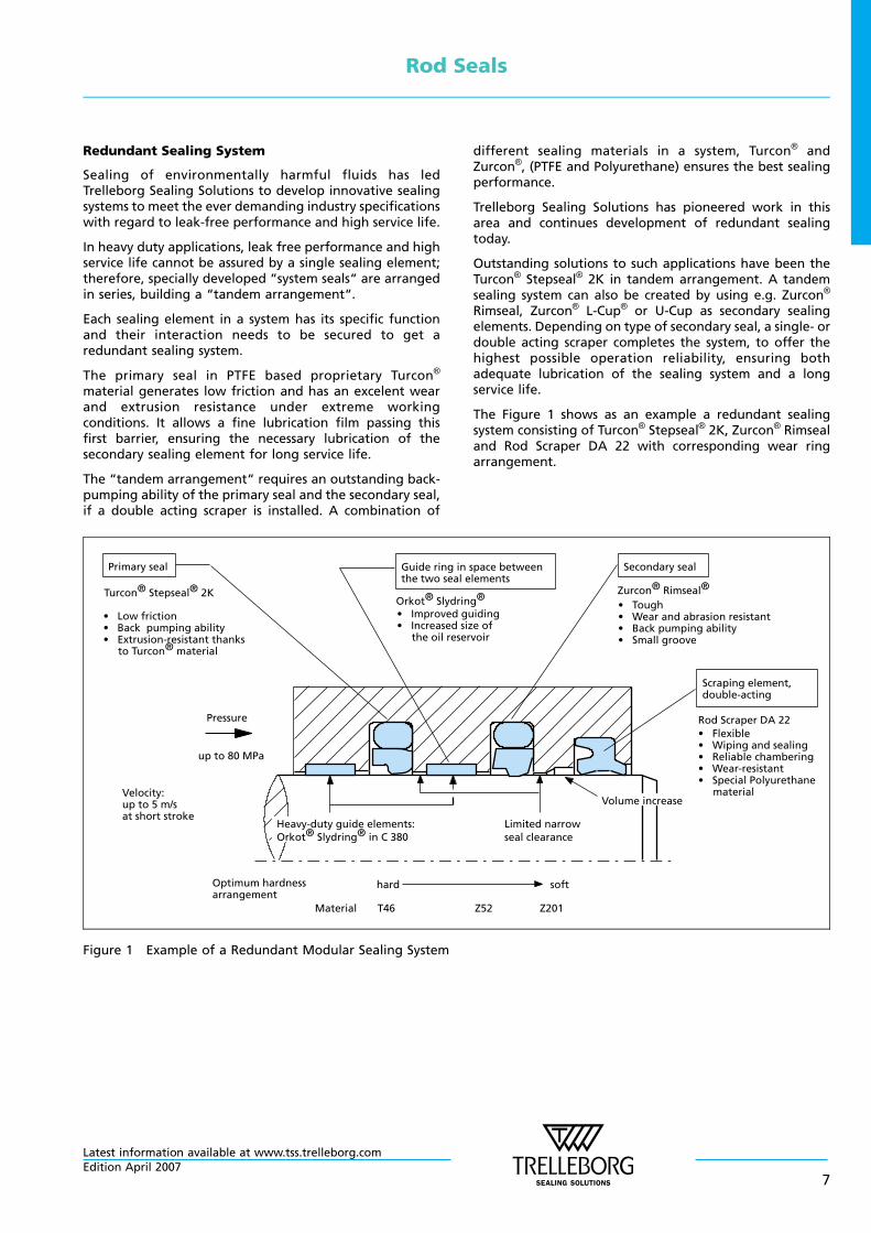
Redundant Sealing System
Sealing of environmentally harmful fluids has ledTrelleborg Sealing Solutions to develop innovative sealingsystems to meet the ever demanding industry specificationswith regard to leak-free performance and high service life.
In heavy duty applications, leak free performance and highservice life cannot be assured by a single sealing element;therefore, specially developed “system seals“ are arrangedin series, building a “tandem arrangement“.
Each sealing element in a system has its specific functionand their interaction needs to be secured to get aredundant sealing system.
The primary seal in PTFE based proprietary Turcon®
material generates low friction and has an excelent wearand extrusion resistance under extreme workingconditions. It allows a fine lubrication film passing thisfirst barrier, ensuring the necessary lubrication of thesecondary sealing element for long service life.
The “tandem arrangement“ requires an outstanding back-pumping ability of the primary seal and the secondary seal,if a double acting scraper is installed. A combination of
different sealing materials in a system, Turcon® andZurcon®, (PTFE and Polyurethane) ensures the best sealingperformance.
Trelleborg Sealing Solutions has pioneered work in thisarea and continues development of redundant sealingtoday.
Outstanding solutions to such applications have been theTurcon® Stepseal® 2K in tandem arrangement. A tandemsealing system can also be created by using e.g. Zurcon®
Rimseal, Zurcon® L-Cup® or U-Cup as secondary sealingelements. Depending on type of secondary seal, a single- ordouble acting scraper completes the system, to offer thehighest possible operation reliability, ensuring bothadequate lubrication of the sealing system and a longservice life.
The Figure 1 shows as an example a redundant sealingsystem consisting of Turcon® Stepseal® 2K, Zurcon® Rimsealand Rod Scraper DA 22 with corresponding wear ringarrangement.
Turcon® Stepseal® 2K
Primary seal Guide ring in space betweenthe two seal elements
Secondary seal
• Tough• Wear and abrasion resistant• Back pumping ability• Small groove
Zurcon® Rimseal®
Scraping element,double-acting
• Flexible• Wiping and sealing• Reliable chambering• Wear-resistant• Special Polyurethane
material
Rod Scraper DA 22Pressure
up to 80 MPa
Velocity:up to 5 m/sat short stroke
Heavy-duty guide elements:Orkot® Slydring® in C 380
Limited narrowseal clearance
Volume increase
Optimum hardnessarrangement
hard soft
Material T46 Z52 Z201
• Low friction• Back pumping ability• Extrusion-resistant thanks
to Turcon® material
• Improved guiding• Increased size of
the oil reservoir
Orkot® Slydring®
Figure 1 Example of a Redundant Modular Sealing System
Rod Seals
Latest information available at www.tss.trelleborg.comEdition April 2007
7
n Design Instructions
Lead-in Chamfers
In order to avoid damage to the rod seal duringinstallation, lead-in chamfers and rounded edges must beprovided on the piston rods (see Figure 2). If this is notpossible for design reasons, a separate installation toolmust be used.
The minimum length of the lead-in chamfer depends onthe profile size of the seal and can be seen from thefollowing tables.
Generally ΔdN min. from Table II, III and IV is recommendedbut ΔdNmust also exceed 0.015 x rod diameter dN (relevantfor big diameter rods).
Table II Elastomer Energized Seals
Lead-in ChamferDiameter reduction
Δd min.
Groove Width
L1*
1.1 2.2
1.4 3.2
1.9 4.2
2.7 6.3
3.5 8.1
4.0 9.5
5.5 13.8
* The dimension L1 for the groove width can be found for all sealseries in the appropriate table “Installation dimensions“.
Table III U-Cups and Variseal®
Lead-inChamferDiameterreductionΔd min.
U-Cups TypeRU0, RU2, RU3
and RU6Groove Depth*
Turcon®
Variseal® M2Series
1.1 3.0 - 3.5 - 4.0
1.1 5.0
1.4 6.0 - 6.5
2.2 7.5 - 8.0 RVA0
2.7 10.0 RVA1,RVA2
3.5 12.5
4.0 15.0 RVA3
5.5 20.0
6.5 RVA4
* The groove depth is calculated from: (d1 - d)/2. The dimensionsfor d1 and d can be found in the tables, “Installationdimensions“.
Table IV Double Delta®
Lead-in Chamfer*Diameter reduction
Δd min.
O—Ring Cross Sec-tion**d2
1.1 1.78 -
1.4 2.40 2.62
1.9 3.00 3.53
2.7 5.33 5.70
3.5 7.00 8.40
* Though not less than 1.5 % of service diameter (bore/roddiameter).
** The O—Ring cross section d2 can be found in the appropriatetable “Installation Dimensions“, from chapter Double Delta®.
Blend radius
15 °–
20 °
Polished
d/2
Figure 2 Lead-in chamfers
Distance between Grooves
When installing tandem seal arrangement or double-actingscraper seals in conjunction with rod seals with backpumping effects such as Turcon® Stepseal® 2K andZurcon® Rimseal, we recommend the followingarrangement:
- Distance between seal grooves and/or scraper seal grooveL = at least groove depth X
- Oil reservoir for collecting the returning oil as shown inFigure 3.
Rod Seals
Latest information available at www.tss.trelleborg.com
8Edition April 2007
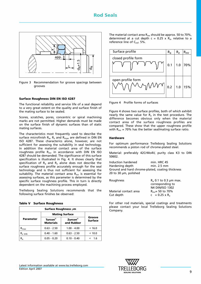
app. 3
L
dN
+1.
5
dN
Figure 3 Recommendation for groove spacings betweengrooves
Surface Roughness DIN EN ISO 4287
The functional reliability and service life of a seal dependto a very great extent on the quality and surface finish ofthe mating surface to be sealed.
Scores, scratches, pores, concentric or spiral machiningmarks are not permitted. Higher demands must be madeon the surface finish of dynamic surfaces than of staticmating surfaces.
The characteristics most frequently used to describe thesurface microfinish Ra, Rz and Rmax are defined in DIN ENISO 4287. These characterics alone, however, are notsufficient for assessing the suitability in seal technology.In addition the material contact area of the surfaceroughness profile Rmr in accordance with DIN EN ISO4287 should be demanded. The significance of this surfacespecification is illustrated in Fig. 4. It shows clearly thatspecification of Ra and Rz alone does not describe thesurface roughness profile accurately enough for the sealtechnology and is thus not sufficient for assessing thesuitability. The material contact area Rmr is essential forassessing surfaces, as this parameter is determined by thespecific surface roughness profile. This in turn is directlydependent on the machining process employed.
Trelleborg Sealing Solutions recommends that thefollowing surface finishes be observed:
Table V Surface Roughness
Surface Roughness µm
Parameter
Mating SurfaceGrooveSurfaceTurcon®
MaterialsZurcon®
and Rubber
Rmax 0.63 - 2.50 1.00 - 4.00 < 16.0
Rz DIN 0.40 - 1.60 0.63 - 2.50 < 10.0
Ra 0.05 - 0.20 0.10 - 0.40 < 1.6
The material contact area Rmr should be approx. 50 to 70%,determined at a cut depth c = 0.25 x Rz, relative to areference line of Cref. 5%.
Surface profile
0.1 1.0 70%
0.2 1.0 15%
closed profile form
open profile form
RmrRzRa
Figure 4 Profile forms of surfaces
Figure 4 shows two surface profiles, both of which exhibitnearly the same value for Rz in the test procedure. Thedifference becomes obvious only when the materialcontact area of the surface roughness profiles arecompared. These show that the upper roughness profilewith Rmr = 70% has the better seal/mating surface ratio.
Hardware
For optimum performance Trelleborg Sealing Solutionsrecommends a piston rod of chrome-plated steel.
Material: preferably 42CrMo4V, purity class K3 to DIN50602.
Induction hardened min. HRC 45Hardening depth min. 2.5 mmGround and hard chrome-plated, coating thickness20 to 30 µm, polished
Roughness Ra 0.1 to 0.3 µm max.corresponding toN4 DIN/ISO 1302
Material contact area Rmr= 50 to 70%Cut depth c = 0.25 x Rz
For other rod materials, special coatings and treatmentsplease contact your local Trelleborg Sealing SolutionsCompany.
Rod Seals
Latest information available at www.tss.trelleborg.comEdition April 2007
9
n Installation Instructions
The following points should be observed beforeinstallation of the seals:
- Ensure the piston rod has a lead-in chamfer; if not, use aninstallation sleeve
- Deburr and chamfer or round sharp edges, cover the tipsof screw threads
- Remove machining residues such as chips, dirt and otherforeign particles and carefully clean all parts
- The seals can be installed more easily if the rod is greasedor oiled. Attention must be paid to the compatibility ofthe seal materials with these lubricants. Use only greasewithout solid additives (e.g. molybdenum disulphide orzinc sulphide).
- Use no sharp-edged installation tools
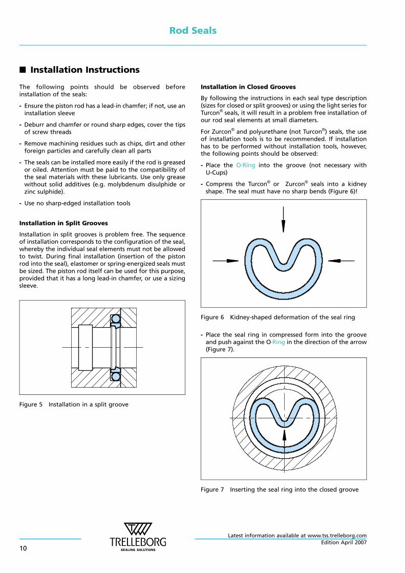
Installation in Split Grooves
Installation in split grooves is problem free. The sequenceof installation corresponds to the configuration of the seal,whereby the individual seal elements must not be allowedto twist. During final installation (insertion of the pistonrod into the seal), elastomer or spring-energized seals mustbe sized. The piston rod itself can be used for this purpose,provided that it has a long lead-in chamfer, or use a sizingsleeve.
Figure 5 Installation in a split groove
Installation in Closed Grooves
By following the instructions in each seal type description(sizes for closed or split grooves) or using the light series forTurcon® seals, it will result in a problem free installation ofour rod seal elements at small diameters.
For Zurcon® and polyurethane (not Turcon®) seals, the useof installation tools is to be recommended. If installationhas to be performed without installation tools, however,the following points should be observed:
- Place the O—Ring into the groove (not necessary withU-Cups)
- Compress the Turcon® or Zurcon® seals into a kidneyshape. The seal must have no sharp bends (Figure 6)!
Figure 6 Kidney-shaped deformation of the seal ring
- Place the seal ring in compressed form into the grooveand push against the O—Ring in the direction of the arrow(Figure 7).
Figure 7 Inserting the seal ring into the closed groove
Rod Seals
Latest information available at www.tss.trelleborg.com
10Edition April 2007
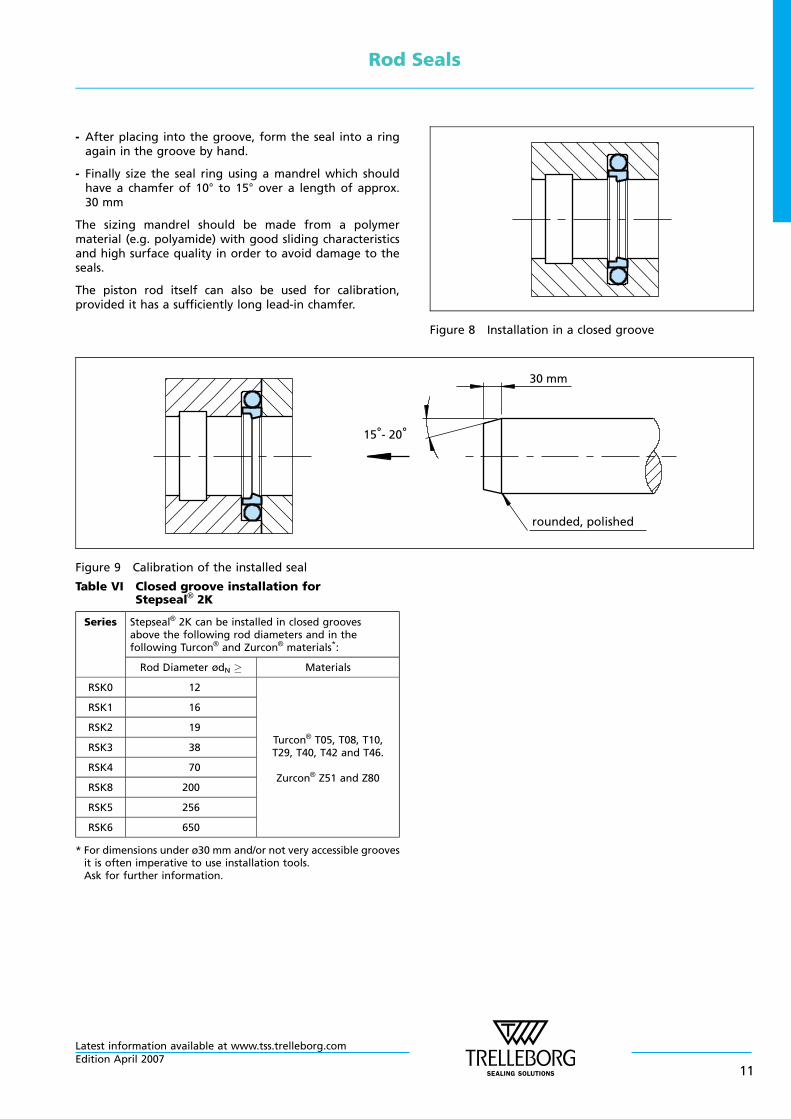
- After placing into the groove, form the seal into a ringagain in the groove by hand.
- Finally size the seal ring using a mandrel which shouldhave a chamfer of 10° to 15° over a length of approx.30 mm
The sizing mandrel should be made from a polymermaterial (e.g. polyamide) with good sliding characteristicsand high surface quality in order to avoid damage to theseals.
The piston rod itself can also be used for calibration,provided it has a sufficiently long lead-in chamfer.
Figure 8 Installation in a closed groove
30 mm
rounded, polished
15°- 20°
Figure 9 Calibration of the installed seal
Table VI Closed groove installation forStepseal® 2K
Series Stepseal® 2K can be installed in closed groovesabove the following rod diameters and in thefollowing Turcon® and Zurcon® materials*:
Rod Diameter ødN Materials
RSK0 12
Turcon® T05, T08, T10,T29, T40, T42 and T46.
Zurcon® Z51 and Z80
RSK1 16
RSK2 19
RSK3 38
RSK4 70
RSK8 200
RSK5 256
RSK6 650
* For dimensions under ø30 mm and/or not very accessible groovesit is often imperative to use installation tools.Ask for further information.
Rod Seals
Latest information available at www.tss.trelleborg.comEdition April 2007
11
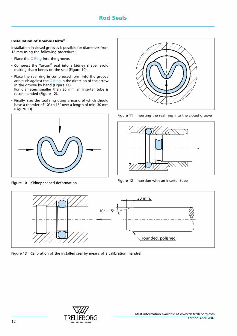
Installation of Double Delta®
Installation in closed grooves is possible for diameters from12 mm using the following procedure:
- Place the O—Ring into the groove.
- Compress the Turcon® seal into a kidney shape, avoidmaking sharp bends on the seal (Figure 10).
- Place the seal ring in compressed form into the grooveand push against the O—Ring in the direction of the arrowin the groove by hand (Figure 11).For diameters smaller than 30 mm an inserter tube isrecommended (Figure 12).
- Finally, size the seal ring using a mandrel which shouldhave a chamfer of 10° to 15° over a length of min. 30 mm(Figure 13).
Figure 10 Kidney-shaped deformation
Figure 11 Inserting the seal ring into the closed groove
Figure 12 Insertion with an inserter tube
rounded, polished
10° - 15°
30 min.
Figure 13 Calibration of the installed seal by means of a calibration mandrel
Rod Seals
Latest information available at www.tss.trelleborg.com
12Edition April 2007
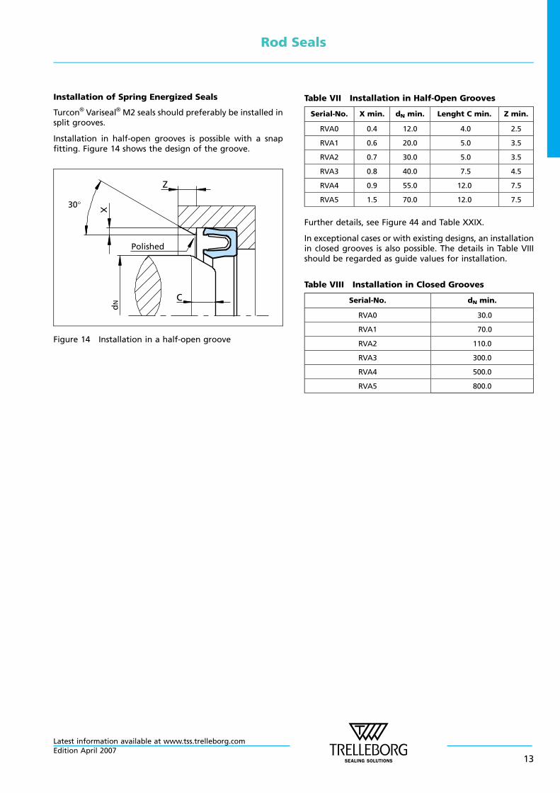
Installation of Spring Energized Seals
Turcon® Variseal® M2 seals should preferably be installed insplit grooves.
Installation in half-open grooves is possible with a snapfitting. Figure 14 shows the design of the groove.
dN
Polished
30°
Z
C
Figure 14 Installation in a half-open groove
Table VII Installation in Half-Open Grooves
Serial-No. X min. dN min. Lenght C min. Z min.
RVA0 0.4 12.0 4.0 2.5
RVA1 0.6 20.0 5.0 3.5
RVA2 0.7 30.0 5.0 3.5
RVA3 0.8 40.0 7.5 4.5
RVA4 0.9 55.0 12.0 7.5
RVA5 1.5 70.0 12.0 7.5
Further details, see Figure 44 and Table XXIX.
In exceptional cases or with existing designs, an installationin closed grooves is also possible. The details in Table VIIIshould be regarded as guide values for installation.
Table VIII Installation in Closed Grooves
Serial-No. dN min.
RVA0 30.0
RVA1 70.0
RVA2 110.0
RVA3 300.0
RVA4 500.0
RVA5 800.0
Rod Seals
Latest information available at www.tss.trelleborg.comEdition April 2007
13
n Quality Criteria
The cost-effective use of seals and bearings is highlyinfluenced by the quality criteria applied in production.Seals and bearings from Trelleborg Sealing Solutions arecontinuously monitored according to strict qualitystandards from material acquisition through to delivery.
Certification of our production plants in accordance withinternational standards QS 9000 / ISO 9000 meets thespecific requirements for quality control and managementof purchasing, production and marketing functions.
Our quality policy is consistently controlled by strictprocedures and guidelines which are implemented withinall strategic areas of the company.
All testing of materials and products is performed inaccordance with accepted test standards and specifications,e.g. random sample testing in accordance with DIN ISO2859, part 1. Inspection specifications correspond tostandards applicable to individual product groups (e.g.for O—Rings: ISO 3601).
Our sealing materials are produced free ofchlorofluorinated hydrocarbons and carcinogenicelements.
The tenth digit of our part number defines the qualitycharacteristics of the part. A hyphen indicates compliancewith standard quality criteria outlined in this catalogue.Customer-specific requirements are indicated by a differentsymbol in this position. Customers who require specialquality criteria should contact their local Trelleborg SealingSolutions sales office for assistance. We have experience inmeeting all Customer quality requirements.
n Storage Instructions
Seals and bearings are often stored as spare parts forprolonged periods. Most rubbers change in physicalproperties during storage and ultimately becomeunserviceable due, e.g., to excessive hardening, softening,cracking, crazing or other surface degradation. Thesechanges may be the result of particular factors orcombination of factors, such as the action ofdeformation, oxygen, ozone, light, heat, humidity or oilsand solvents.
With a few simple precautions, the shelf life of theseproducts can be considerably lengthened.
Fundamental instructions on storage, cleaning andmaintenance of elastomeric seal elements are describedin international standards, such as:
DIN 7716 / BS 3F68: 1977,ISO 2230, orDIN 9088
The standards give several recommendations for thestorage and the shelf life of elastomers, depending onthe material classes.
The following recommendations are based on the severalstandards and are intended to provide the most suitableconditions for storage of rubbers. They should be observedto maintain the optimum physical and chemical values ofthe parts:
Heat
The storage temperature should preferable be between+5 °C and +25 °C. Direct contact with sources of heat suchas boilers, radiators and direct sunlight should be avoided.If the storage temperature is below +15 °C, care should betaken to avoid distorting them during handling at thattemperature as they may have stiffened. In this case thetemperature of the articles should be raised toapproximately +20 °C before they are put into service.
Humidity
The relative humidity in the store room should be below70 %. Very moist or very dry conditions should be avoided.Condensation should not occur.
Light
Elastomeric seals should be protected from light sources, inparticular direct sunlight or strong artificial light with anultraviolet content. The individual storage bags offer thebest protection as long as they are UV resistant.It is advisable to cover any windows of storage rooms witha red or orange coating or screen.
Radiation
Precaution should be taken to protect stored articles fromall sources of ionising radiation likely to cause damage tostored articles.
Oxygen and ozone
Where possible, elastomeric materials should be protectedfrom circulating air by wrapping, storage in airtightcontainers or by other suitable means.
As ozone is particular deleterious to some elastomericseals, storage rooms should not contain any equipmentthat is capable of generating ozone, such as mercuryvapour lamps, high voltage electrical equipment, electricmotors or other equipment which may give rise to electricsparks or silent electrical discharges. Combustion gases andorganic vapour should be excluded from storage roomsalas they may give rise to ozone via photochemicalprocesse
Deformation
Elastomeric materials should, wherever possible, be storedin a relaxed condition free from tension, compression orother deformation. Where articles are packed in astrain—free condition they should be stored in theiroriginal packaging.
Rod Seals
Latest information available at www.tss.trelleborg.com
14Edition April 2007
Contact with liquid and semi-solid materials
Elastomeric seals should not be allowed to come intocontact with solvents, oils, greases or any other semi-solidmaterials at any time during storage, unless so packed bythe manufacturer.
Contact with metal and non-metals
Direct contact with certain metals, e.g. manganese, ironand particularly copper and its alloys, e.g. brass andcompounds of these materials are known to havedeleterious effects on some rubbers. Elastomeric sealsshould not be stored in contact with such metals.
Because of possible transfer of plasticisers or otheringredients, rubbers must not be stored in contact withPVC. Different rubbers should preferably be separatedfrom each other.
Cleaning
Where necessary, cleaning should be carried out with theaid of soap and water or methylated spirits. Water shouldnot, however, be permitted to come into contact withfabric reinforced components, bonded seals (because ofcorrosion) or polyurethane rubbers. Disinfectants or otherorganic solvents as well as sharp-edged objects must not beused. The articles should be dried at room temperature andnot placed near a source of heat.
Shelf life and shelf life control
The useful life of a elastomeric seals will depend to a largeextend on the type of rubber. When stored under therecommended conditions (above sections) the below givenshelf life of several materials should be considered.
AU, Thermoplastics 4 years
NBR, HNBR, CR 6 years
EPDM 8 years
FKM, VMQ, FVMQ 10 years
FFKM, Isolast® 18 years
PTFE, Turcon® unlimited
Elastomeric seals should be inspected after the givenperiod. After this giving an extension period is possible.
Rubber details and components less than 1.5 mm thick areliable to be more seriously affected by oxidationdegradation even when stored in satisfactory conditionsas recommended. Therefore they may be inspected andtested more frequently than it is mentioned above.
Rubber details / seals in assembled components
It is recommended that the units should be exercised atleast every six months and that the maximum period arubber detail be allowed to remain assembled within astored unit, without inspection, be a total of the initialperiod stated above and the extension period. Naturallythis will depend on the design of the unit concerned.
Rod Seals
Latest information available at www.tss.trelleborg.comEdition April 2007
15
Rod Seals
Latest information available at www.tss.trelleborg.com
16Edition April 2007
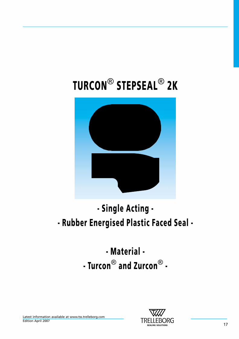
TURCON® STEPSEAL® 2K
- Single Acting -
- Rubber Energised Plastic Faced Seal -
- Material -
- Turcon® and Zurcon® -
Latest information available at www.tss.trelleborg.comEdition April 2007
17

Latest information available at www.tss.trelleborg.com
18Edition April 2007
n Turcon® Stepseal® 2K*
Description
Rod seals must exhibit no dynamic leakage to theatmosphere side under all operating conditions and mustbe statically completely leak tight when the machine is at astandstill. Furthermore, they should achieve a high degreeof mechanical efficiency through low friction and be easyto install in small grooves. Costs and service life must meetthe high expectations of the operator.
The rod seal Turcon® Stepseal® 2K comes closest tosatisfying these ideal demands. Since the first Stepseal®
was patented and introduced to the market in 1972,Trelleborg Sealing Solutions has maintained the series astechnically outstanding seal elements through continuousinnovative further development of the design and of theTurcon® and Zurcon® materials. Turcon® Stepseal® 2Kcontinues the tradition for improvement.
With the introduction of Stepseal® it was possible for thefirst time to arrange several seals, one behind the other,thus allowing statically and dynamically tight double-acting tandem seal configurations to be created, withoutany disturbing build-up of intermediate pressure. The
single-acting seal element is made of high-grade Turcon®
or Zurcon® materials with outstanding sliding and wearresistance properties. It is installed according to ISO 7425/2and Trelleborg Sealing Solutions standard grooves, usingan O—Ring as energizing element.
p
O-Ring
Turcon®
Seal ring
Figure 15 Turcon® Stepseal® 2K
Turcon® and Zurcon®
Low friction, no stick-slipHigh form stability and wearresistanceMeets demanding serviceconditionsHigh flexibility for easyinstallation
GeometryPatented and patent pendinggeometryProven seal edge designResist damage duringinstallation and service
Elastomer O-RingHigh flexibility to compensatehardware tolerances andmovement. Elastomer materialsavailable to meet a widevariety of service conditions
O-Ring Relief ChamferReduced seal load underpressure.Reduced seal friction
Contoured RearImproved back-pumping ofresidual oil film for increasedsealing efficiency.Increased hardware tolerancesIncreased radial clearance
* Patented and patent pending geometry
Turcon® Stepseal® 2K
Latest information available at www.tss.trelleborg.comEdition April 2007
19
Method of operation
The sealing performance of Stepseal® 2K (Figure 15) resultsfrom the hydrodynamic properties of the seal. The classicStepseal® seal edge creates a steep contact pressuregradient on the high pressure side and a shallow contactpressure gradient on the low pressure side. The controlledpressure gradients minimizes fluid adherence to the pistonrod during the extending stroke, and enables residual fluidfilm on the rod to be returned into the system on thereturn stroke. This is united with new patented and patentapplied design features which further improve theperformance of Stepseal® 2K under severe serviceconditions.
The O—Ring relief chamfer reduces pressure loading on theseal, whereby contact with the rod is optimised and sealingperformance is improved at high service pressures. Thespecial high-lift rear chamfer combines a smoothdownstream sealing face with the ability to meet largeradial clearances and hardware tolerances.
Stepseal® 2K gives high static and dynamic sealingperformance, and the build-up of intermediate pressureoften found with tandem seal configurations (see Figure16) is efficiently suppressed.
P R E S S U R E
Stepseal® K•
Stepseal® 2K
•
Turcon® Stepseal® 2K possesses superiorextrusion resistance under all serviceconditions and allows hardwareclearance to be significantly increased.
Increased Clearance
RA
DIA
LC
LE
AR
AN
CE
Advantages
- High static and dynamic sealing effect
- High extrusion resistance, meets high hardwareclearances
- Low friction, high efficiency
- Stick-slip free starting, no sticking
- High abrasion resistance, high operational reliability
- Wide range of application temperatures and highresistance to chemicals, depending on the choice ofO—Ring material
- Simple installation without seal edge deformation
- Available for all diameters up to 2.600 mm rod dia.
C Y C L E S
Stepseal® 2K
Stepseal® K
•
•
Turcon® Stepseal® 2K offers auniform, low frictioncharacteristic, throughout its life,including the run in period.
Improved Friction Performance
FR
ICT
ION
FO
RC
E
Technical data
Operating pressure: up to 80 MPa
Speed: up to 15 m/s with reciprocatingmovements, frequency up to 5 Hz
Temperature: -45°C to +200°Cdepending on O—Ring material)
Media: Mineral oil-based hydraulic fluids,flame retardant hydraulic fluids,environmentally safe hydraulicfluids (bio-oils), water and others,depending on the O—Ring material(see Table X)
Clearance: The maximum permissible radialclearance Smax is shown in TableXI, as a function of the operatingpressure and functional diameter.
Important Note:The above data are maximum values and cannotbe used at the same time. e.g. the maximumoperating speed depends on material type,pressure, temperature and gap value.Temperature range also dependent on medium.
Turcon® Stepseal® 2K
Latest information available at www.tss.trelleborg.com
20Edition April 2007
Materials
The following material combination has proven effectivefor applications with hydraulic oils containing zinc:
Turcon® Stepseal® 2K: Turcon® T46
O—Ring: NBR, 70 Shore A NFKM, 70 Shore A V
Set code: T46N/T46V
For specific applications, other material combinations aslisted in Table X, may also be used.
Series
Different cross-section sizes are recommended as afunction of the seal diameters. These are the criteria forthese recommendations.
Table XI, shows the relationship between the series numberaccording to the seal diameter range and the differentapplication class sizes. These application classes are:
Standard application: General applications in whichno exceptional operatingconditions exist.
Light application: Applications with demands forreduced friction or for smallergrooves.
Heavy-duty application: For exceptional operatingloads such as high pressures,pressure peaks, etc.
Table IX Available range
Series No.Rod Diameter
dN f8/h9
RSK00 2.0 - 130.0
RSK10 6.0 - 250.0
RSK20 10.0 - 450.0
RSK30 12.0 - 650.0
RSK40 38.0 - 650.0
RSK80 200.0 - 999.9
RSK50 256.0 - 999.9
RSK5X 1000.0 - 1200.0
RSK60 650.0 - 999.9
RSK6X 1000.0 - 2600.0
For the recommended range see Table XI.
Application Examples
- Mobile hydraulic
- Standard cylinders
- Machine tools
- Injection moulding machines
- Presses
- Automobile industry
- Hydraulic hammers
- Servo hydraulics
Redundant Sealing System
In many applications, secondary seal systems aredemanded. Figure 16 shows such a tandem configurationwith the Stepseal® 2K.
Primary sealTurcon® Stepseal® 2K
Secondary seal
Double-acting scraper
p
Zurcon® Rimseal
Figure 16 Turcon® Stepseal® 2K and Zurcon® Rimseal intandem configuration
In this configuration it must be noted that a sufficientlylarge space is formed between the seals to take thehydraulic fluid, as shown in the figure.
Depending on the application and the operatingconditions, the combination of different materials offersa further improvement in the sealing efficiency and theservice life of the system, e.g. in hydraulic cylinders subjectto high loads and under rough operating conditions, theprimary seal should be made of Turcon® and the secondaryseal of Zurcon®.
Turcon® Stepseal® 2K
Latest information available at www.tss.trelleborg.comEdition April 2007
21
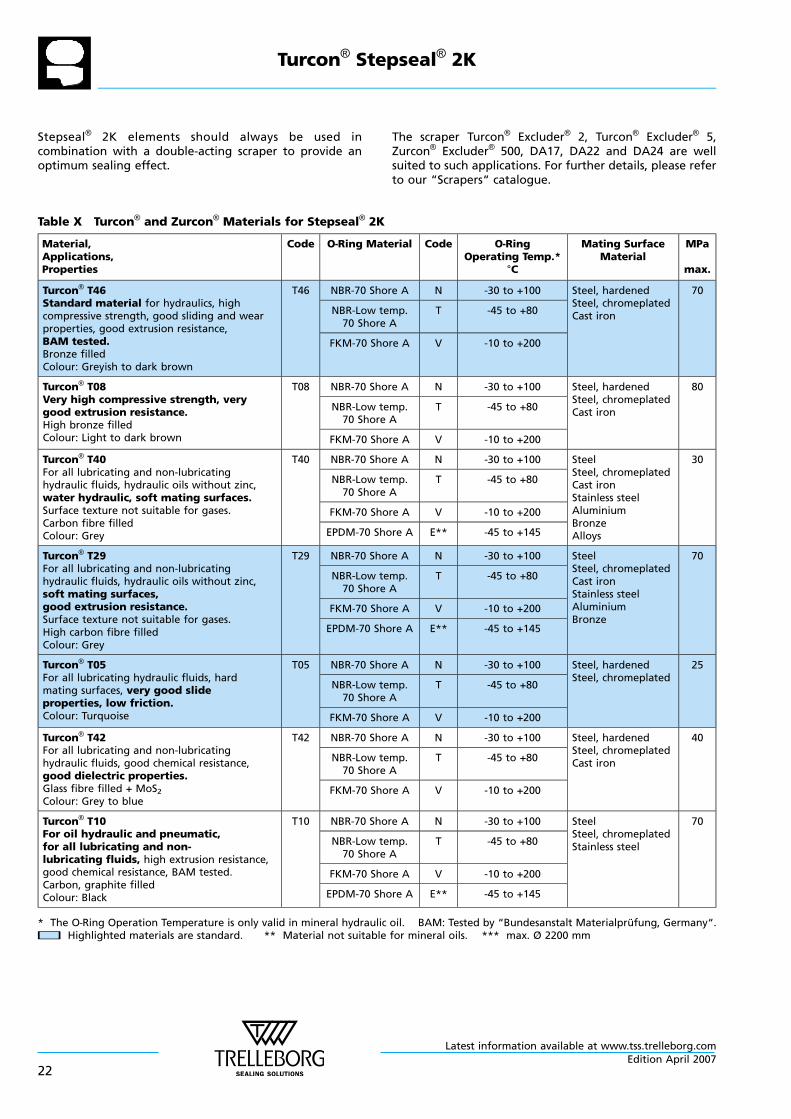
Stepseal® 2K elements should always be used incombination with a double-acting scraper to provide anoptimum sealing effect.
The scraper Turcon® Excluder® 2, Turcon® Excluder® 5,Zurcon® Excluder® 500, DA17, DA22 and DA24 are wellsuited to such applications. For further details, please referto our “Scrapers“ catalogue.
Table X Turcon® and Zurcon® Materials for Stepseal® 2K
Material,Applications,Properties
Code O—Ring Material Code O—RingOperating Temp.*
°C
Mating SurfaceMaterial
MPa
max.
Turcon® T46Standard material for hydraulics, highcompressive strength, good sliding and wearproperties, good extrusion resistance,BAM tested.Bronze filledColour: Greyish to dark brown
T46 NBR-70 Shore A N -30 to +100 Steel, hardenedSteel, chromeplatedCast iron
70
NBR-Low temp.70 Shore A
T -45 to +80
FKM-70 Shore A V -10 to +200
Turcon® T08Very high compressive strength, verygood extrusion resistance.High bronze filledColour: Light to dark brown
T08 NBR-70 Shore A N -30 to +100 Steel, hardenedSteel, chromeplatedCast iron
80
NBR-Low temp.70 Shore A
T -45 to +80
FKM-70 Shore A V -10 to +200
Turcon® T40For all lubricating and non-lubricatinghydraulic fluids, hydraulic oils without zinc,water hydraulic, soft mating surfaces.Surface texture not suitable for gases.Carbon fibre filledColour: Grey
T40 NBR-70 Shore A N -30 to +100 SteelSteel, chromeplatedCast ironStainless steelAluminiumBronzeAlloys
30
NBR-Low temp.70 Shore A
T -45 to +80
FKM-70 Shore A V -10 to +200
EPDM-70 Shore A E** -45 to +145
Turcon® T29For all lubricating and non-lubricatinghydraulic fluids, hydraulic oils without zinc,soft mating surfaces,good extrusion resistance.Surface texture not suitable for gases.High carbon fibre filledColour: Grey
T29 NBR-70 Shore A N -30 to +100 SteelSteel, chromeplatedCast ironStainless steelAluminiumBronze
70
NBR-Low temp.70 Shore A
T -45 to +80
FKM-70 Shore A V -10 to +200
EPDM-70 Shore A E** -45 to +145
Turcon® T05For all lubricating hydraulic fluids, hardmating surfaces, very good slideproperties, low friction.Colour: Turquoise
T05 NBR-70 Shore A N -30 to +100 Steel, hardenedSteel, chromeplated
25
NBR-Low temp.70 Shore A
T -45 to +80
FKM-70 Shore A V -10 to +200
Turcon® T42For all lubricating and non-lubricatinghydraulic fluids, good chemical resistance,good dielectric properties.Glass fibre filled + MoS2Colour: Grey to blue
T42 NBR-70 Shore A N -30 to +100 Steel, hardenedSteel, chromeplatedCast iron
40
NBR-Low temp.70 Shore A
T -45 to +80
FKM-70 Shore A V -10 to +200
Turcon® T10For oil hydraulic and pneumatic,for all lubricating and non-lubricating fluids, high extrusion resistance,good chemical resistance, BAM tested.Carbon, graphite filledColour: Black
T10 NBR-70 Shore A N -30 to +100 SteelSteel, chromeplatedStainless steel
70
NBR-Low temp.70 Shore A
T -45 to +80
FKM-70 Shore A V -10 to +200
EPDM-70 Shore A E** -45 to +145
* The O—Ring Operation Temperature is only valid in mineral hydraulic oil. BAM: Tested by “Bundesanstalt Materialprufung, Germany“.nn Highlighted materials are standard. ** Material not suitable for mineral oils. *** max. Ø 2200 mm
Turcon® Stepseal® 2K
Latest information available at www.tss.trelleborg.com
22Edition April 2007
Material,Applications,Properties
Code O—Ring Material Code O—RingOperating Temp.*
°C
Mating SurfaceMaterial
MPa
max.
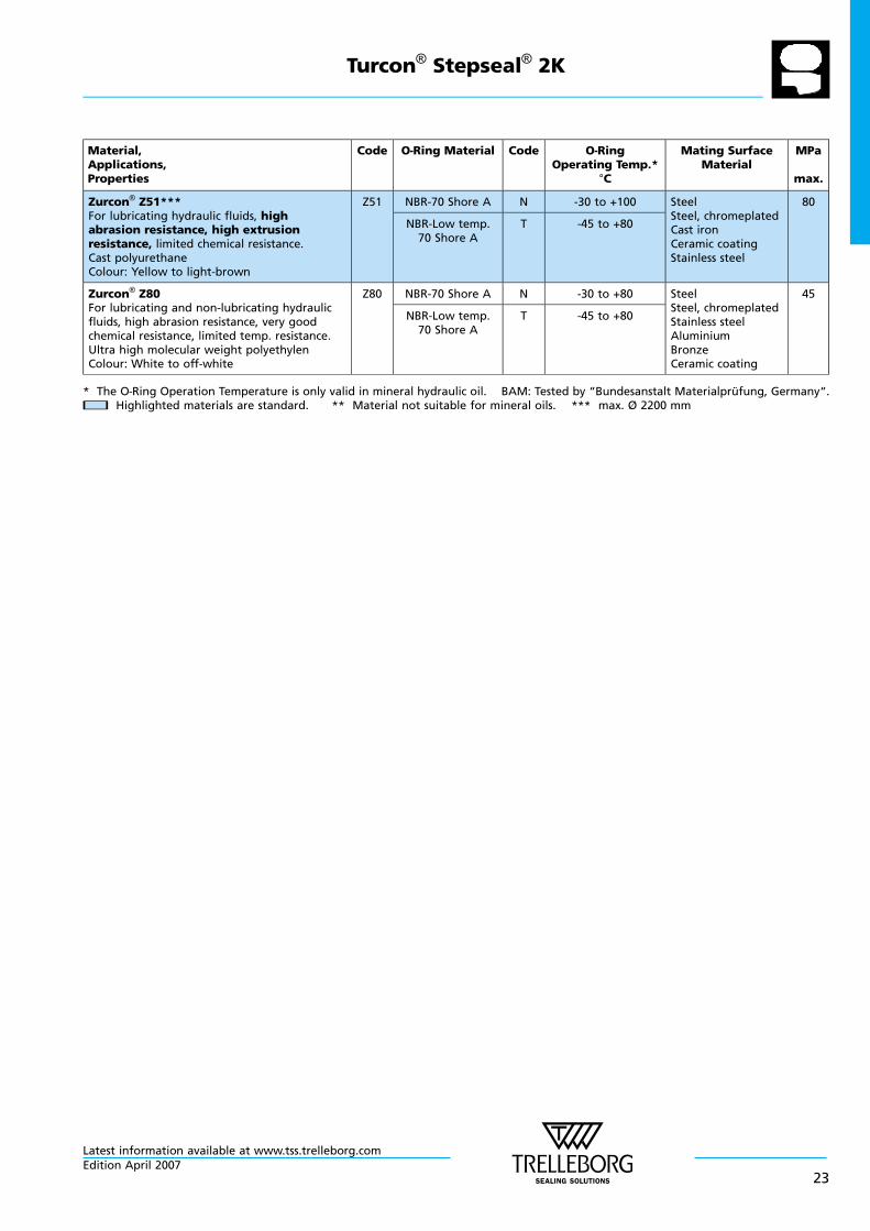
Zurcon® Z51***For lubricating hydraulic fluids, highabrasion resistance, high extrusionresistance, limited chemical resistance.Cast polyurethaneColour: Yellow to light-brown
Z51 NBR-70 Shore A N -30 to +100 SteelSteel, chromeplatedCast ironCeramic coatingStainless steel
80
NBR-Low temp.70 Shore A
T -45 to +80
Zurcon® Z80For lubricating and non-lubricating hydraulicfluids, high abrasion resistance, very goodchemical resistance, limited temp. resistance.Ultra high molecular weight polyethylenColour: White to off-white
Z80 NBR-70 Shore A N -30 to +80 SteelSteel, chromeplatedStainless steelAluminiumBronzeCeramic coating
45
NBR-Low temp.70 Shore A
T -45 to +80
* The O—Ring Operation Temperature is only valid in mineral hydraulic oil. BAM: Tested by “Bundesanstalt Materialprufung, Germany“.nn Highlighted materials are standard. ** Material not suitable for mineral oils. *** max. Ø 2200 mm
Turcon® Stepseal® 2K
Latest information available at www.tss.trelleborg.comEdition April 2007
23
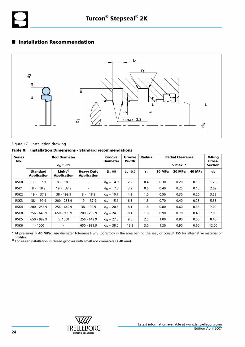
n Installation Recommendation
r max. 0.3S S
dND
1
d2
L1
r1
Figure 17 Installation drawing
Table XI Installation Dimensions - Standard recommendations
SeriesNo.
Rod Diameter
dN f8/h9
GrooveDiameter
GrooveWidth
Radius Radial Clearance
S max. *
O—RingCross-Section
StandardApplication
Light1)
ApplicationHeavy DutyApplication
D1 H9 L1 +0.2 r1 10 MPa 20 MPa 40 MPa d2
RSK0 3 - 7.9 8 - 18.9 - dN + 4.9 2.2 0.4 0.30 0.20 0.15 1.78
RSK1 8 - 18.9 19 - 37.9 - dN + 7.3 3.2 0.6 0.40 0.25 0.15 2.62
RSK2 19 - 37.9 38 - 199.9 8 - 18.9 dN + 10.7 4.2 1.0 0.50 0.30 0.20 3.53
RSK3 38 - 199.9 200 - 255.9 19 - 37.9 dN + 15.1 6.3 1.3 0.70 0.40 0.25 5.33
RSK4 200 - 255.9 256 - 649.9 38 - 199.9 dN + 20.5 8.1 1.8 0.80 0.60 0.35 7.00
RSK8 256 - 649.9 650 - 999.9 200 - 255.9 dN + 24.0 8.1 1.8 0.90 0.70 0.40 7.00
RSK5 650 - 999.9 1000 256 - 649.9 dN + 27.3 9.5 2.5 1.00 0.80 0.50 8.40
RSK6 1000 - 650 - 999.9 dN + 38.0 13.8 3.0 1.20 0.90 0.60 12.00
* At pressures > 40 MPa: use diameter tolerance H8/f8 (bore/rod) in the area behind the seal; or consult TSS for alternative material orprofiles.
1) For easier installation in closed grooves with small rod diameters (< 40 mm).
Turcon® Stepseal® 2K
Latest information available at www.tss.trelleborg.com
24Edition April 2007
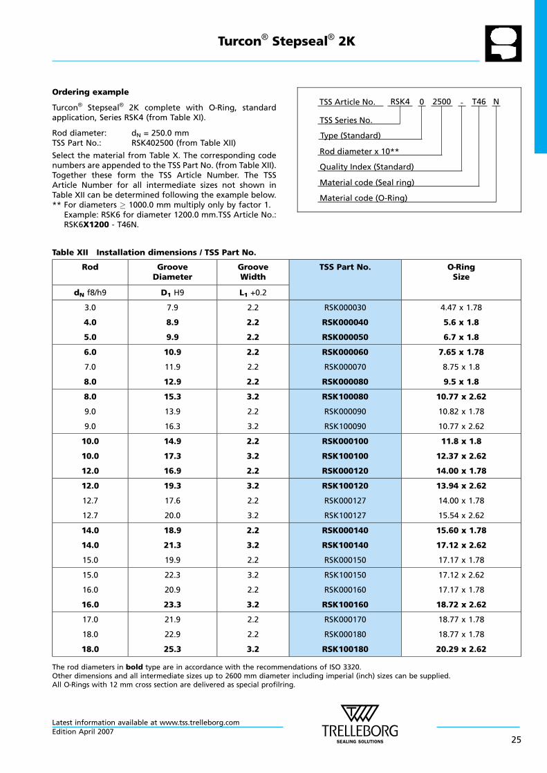
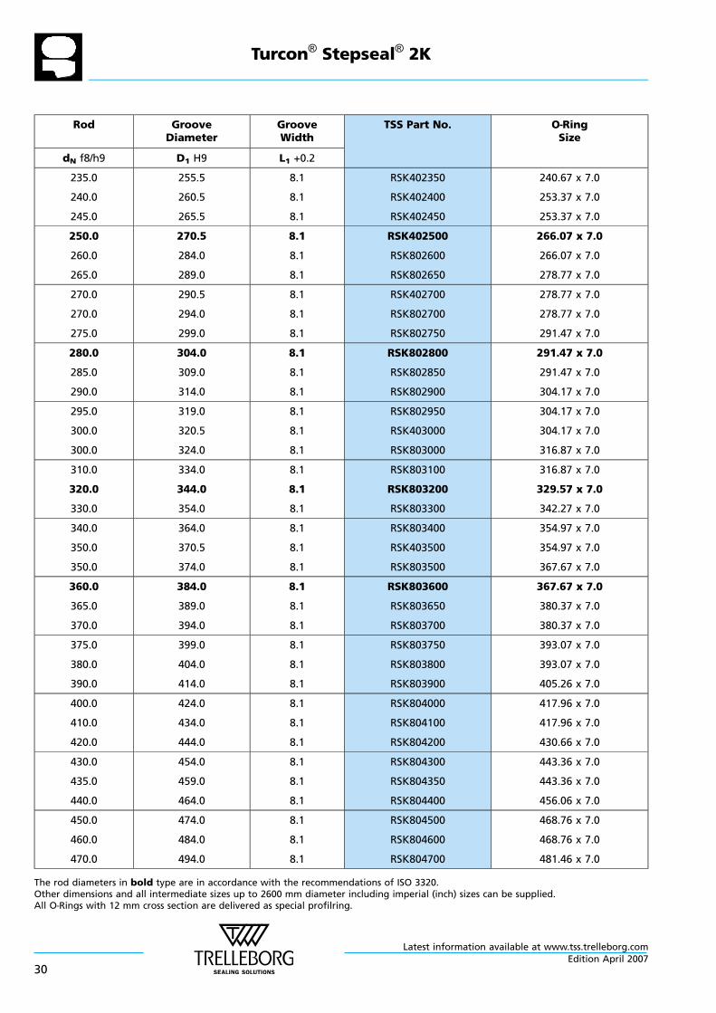
Ordering example
Turcon® Stepseal® 2K complete with O—Ring, standardapplication, Series RSK4 (from Table XI).
Rod diameter: dN = 250.0 mmTSS Part No.: RSK402500 (from Table XII)
Select the material from Table X. The corresponding codenumbers are appended to the TSS Part No. (from Table XII).Together these form the TSS Article Number. The TSSArticle Number for all intermediate sizes not shown inTable XII can be determined following the example below.** For diameters 1000.0 mm multiply only by factor 1.
Example: RSK6 for diameter 1200.0 mm.TSS Article No.:RSK6X1200 - T46N.
Material code (Seal ring)
TSS Series No.
TSS Article No. T462500 N
Material code (O-Ring)
Rod diameter x 10**
RSK4
Quality Index (Standard)
-
Type (Standard)
0
Table XII Installation dimensions / TSS Part No.
Rod GrooveDiameter
GrooveWidth
TSS Part No. O—RingSize
dN f8/h9 D1 H9 L1 +0.2
3.0
4.0
5.0
7.9
8.9
9.9
2.2
2.2
2.2
RSK000030
RSK000040
RSK000050
4.47 x 1.78
5.6 x 1.8
6.7 x 1.8
6.0
7.0
8.0
10.9
11.9
12.9
2.2
2.2
2.2
RSK000060
RSK000070
RSK000080
7.65 x 1.78
8.75 x 1.8
9.5 x 1.8
8.0
9.0
9.0
15.3
13.9
16.3
3.2
2.2
3.2
RSK100080
RSK000090
RSK100090
10.77 x 2.62
10.82 x 1.78
10.77 x 2.62
10.0
10.0
12.0
14.9
17.3
16.9
2.2
3.2
2.2
RSK000100
RSK100100
RSK000120
11.8 x 1.8
12.37 x 2.62
14.00 x 1.78
12.0
12.7
12.7
19.3
17.6
20.0
3.2
2.2
3.2
RSK100120
RSK000127
RSK100127
13.94 x 2.62
14.00 x 1.78
15.54 x 2.62
14.0
14.0
15.0
18.9
21.3
19.9
2.2
3.2
2.2
RSK000140
RSK100140
RSK000150
15.60 x 1.78
17.12 x 2.62
17.17 x 1.78
15.0
16.0
16.0
22.3
20.9
23.3
3.2
2.2
3.2
RSK100150
RSK000160
RSK100160
17.12 x 2.62
17.17 x 1.78
18.72 x 2.62
17.0
18.0
18.0
21.9
22.9
25.3
2.2
2.2
3.2
RSK000170
RSK000180
RSK100180
18.77 x 1.78
18.77 x 1.78
20.29 x 2.62
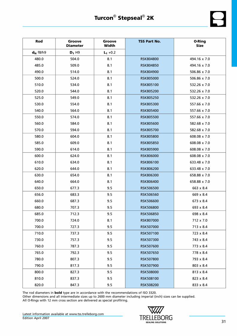
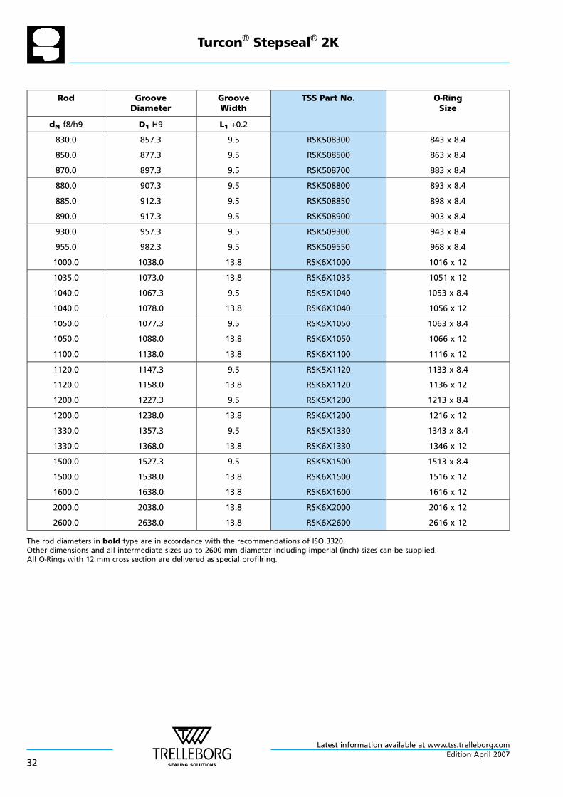
The rod diameters in bold type are in accordance with the recommendations of ISO 3320.Other dimensions and all intermediate sizes up to 2600 mm diameter including imperial (inch) sizes can be supplied.All O—Rings with 12 mm cross section are delivered as special profilring.
Turcon® Stepseal® 2K
Latest information available at www.tss.trelleborg.comEdition April 2007
25
Rod GrooveDiameter
GrooveWidth
TSS Part No. O—RingSize
dN f8/h9 D1 H9 L1 +0.2
19.0
20.0
20.0
29.7
27.3
30.7
4.2
3.2
4.2
RSK200190
RSK100200
RSK200200
23.40 x 3.53
21.89 x 2.62
23.40 x 3.53
22.0
22.0
24.0
29.3
32.7
31.3
3.2
4.2
3.2
RSK100220
RSK200220
RSK100240
25.07 x 2.62
26.58 x 3.53
26.64 x 2.62
25.0
25.0
25.4
32.3
35.7
32.7
3.2
4.2
3.2
RSK100250
RSK200250
RSK100254
28.24 x 2.62
29.75 x 3.53
28.24 x 2.62
25.4
26.0
26.0
36.1
33.3
36.7
4.2
3.2
4.2
RSK200254
RSK100260
RSK200260
29.75 x 3.53
28.24 x 2.62
29.75 x 3.53
28.0
28.0
28.575
35.3
38.7
35.875
3.2
4.2
3.2
RSK100280
RSK200280
RSK100286
29.82 x 2.62
32.92 x 3.53
31.42 x 2.62
30.0
30.0
32.0
37.3
40.7
39.3
3.2
4.2
3.2
RSK100300
RSK200300
RSK100320
32.99 x 2.62
34.52 x 3.53
34.59 x 2.62
32.0
35.0
35.0
42.7
42.3
45.7
4.2
3.2
4.2
RSK200320
RSK100350
RSK200350
36.09 x 3.53
37.77 x 2.62
37.69 x 3.53
36.0
36.0
37.0
43.3
46.7
44.3
3.2
4.2
3.2
RSK100360
RSK200360
RSK100370
39.34 x 2.62
40.87 x 3.53
39.34 2.62
37.0
38.0
38.0
47.7
48.7
53.1
4.2
4.2
6.3
RSK200370
RSK200380
RSK300380
40.87 x 3.53
40.87 x 3.53
43.82 x 5.33
40.0
40.0
42.0
50.7
55.1
52.7
4.2
6.3
4.2
RSK200400
RSK300400
RSK200420
44.04 x 3.53
43.82 x 5.33
47.22 x 3.53
42.0
43.0
44.45
57.1
53.7
59.55
6.3
4.2
6.3
RSK300420
RSK200430
RSK300444
46.99 x 5.33
47.22 x 3.53
50.17 x 5.33
45.0
45.0
48.0
55.7
60.1
58.7
4.2
6.3
4.2
RSK200450
RSK300450
RSK200480
50.39 x 3.53
50.17 x 5.33
51.5 x 3.55
The rod diameters in bold type are in accordance with the recommendations of ISO 3320.Other dimensions and all intermediate sizes up to 2600 mm diameter including imperial (inch) sizes can be supplied.All O—Rings with 12 mm cross section are delivered as special profilring.
Turcon® Stepseal® 2K
Latest information available at www.tss.trelleborg.com
26Edition April 2007
Rod GrooveDiameter
GrooveWidth
TSS Part No. O—RingSize
dN f8/h9 D1 H9 L1 +0.2
48.0
50.0
50.0
63.1
60.7
65.1
6.3
4.2
6.3
RSK300480
RSK200500
RSK300500
53.34 x 5.33
53.57 x 3.53
56.52 x 5.33
50.8
50.8
52.0
61.5
65.9
62.7
4.2
6.3
4.2
RSK200508
RSK300508
RSK200520
53.57 x 3.53
56.52 x 5.33
56.74 x 3.53
52.0
54.0
55.0
67.1
69.1
65.7
6.3
6.3
4.2
RSK300520
RSK300540
RSK200550
56.52 x 5.33
59.69 x 5.33
59.92 x 3.53
55.0
56.0
56.0
70.1
66.7
71.1
6.3
4.2
6.3
RSK300550
RSK200560
RSK300560
59.69 x 5.33
59.92 x 3.53
62.87 x 5.33
56.0
57.0
59.0
76.5
72.1
69.7
8.1
6.3
4.2
RSK400560
RSK300570
RSK200590
63 x 7.0
62.87 x 5.33
63.09 x 3.53
60.0
60.0
63.0
70.7
75.1
73.7
4.2
6.3
4.2
RSK200600
RSK300600
RSK200630
63.09 x 3.53
66.04 x 5.33
66.27 x 3.53
63.0
63.5
65.0
78.1
78.6
75.7
6.3
6.3
4.2
RSK300630
RSK300635
RSK200650
69.22 x 5.33
69.22 x 5.33
69.44 x 3.53
65.0
67.0
69.0
80.1
77.7
84.1
6.3
4.2
6.3
RSK300650
RSK200670
RSK300690
69.22 x 5.33
72.62 x 3.53
75.57 x 5.33
70.0
70.0
70.0
80.7
85.1
90.5
4.2
6.3
8.1
RSK200700
RSK300700
RSK400700
75.79 x 3.53
75.57 x 5.33
78 x 7.0
72.0
73.0
75.0
82.7
88.1
85.7
4.2
6.3
4.2
RSK200720
RSK300730
RSK200750
75.79 x 3.53
78.74 x 5.33
78.97 x 3.53
75.0
76.2
78.0
90.1
91.3
93.1
6.3
6.3
6.3
RSK300750
RSK300762
RSK300780
81.92 x 5.33
81.92 x 5.33
85.09 x 5.33
80.0
80.0
80.0
90.7
95.1
100.5
4.2
6.3
8.1
RSK200800
RSK300800
RSK400800
85.32 x 3.53
85.09 x 5.33
88 x 7.0
The rod diameters in bold type are in accordance with the recommendations of ISO 3320.Other dimensions and all intermediate sizes up to 2600 mm diameter including imperial (inch) sizes can be supplied.All O—Rings with 12 mm cross section are delivered as special profilring.
* Patented and patent pending geometry
Turcon® Stepseal® 2K
Latest information available at www.tss.trelleborg.comEdition April 2007
27
Rod GrooveDiameter
GrooveWidth
TSS Part No. O—RingSize
dN f8/h9 D1 H9 L1 +0.2
82.5
83.0
85.0
97.6
93.7
95.7
6.3
4.2
4.2
RSK300825
RSK200830
RSK200850
88.27 x 5.33
88.49 x 3.53
88.49 x 3.53
85.0
85.0
89.0
100.1
105.5
104.1
6.3
8.1
6.3
RSK300850
RSK400850
RSK300890
91.44 x 5.33
93 x 7.0
94.62 x 5.33
90.0
90.0
90.0
100.7
105.1
110.5
4.2
6.3
8.1
RSK200900
RSK300900
RSK400900
94.84 x 3.53
94.62 x 5.33
98 x 7.0
92.0
92.0
95.0
102.7
107.1
105.7
4.2
6.3
4.2
RSK200920
RSK300920
RSK200950
98.02 x 3.53
97.79 x 5.33
101.19 x 3.53
95.0
100.0
100.0
110.1
110.7
115.1
6.3
4.2
6.3
RSK300950
RSK201000
RSK301000
100.97 x 5.33
104.37 x 3.53
107.32 x 5.33
100.0
101.6
104.7
120.5
116.7
119.8
8.1
6.3
6.3
RSK401000
RSK301016
RSK301047
108 x 7.0
107.32 x 5.33
110.49 x 5.33
105.0
105.0
110.0
120.1
125.5
120.7
6.3
8.1
4.2
RSK301050
RSK401050
RSK201100
110.49 x 5.33
113.67 x 7.0
113.89 x 3.53
110.0
110.0
115.0
125.1
130.5
130.1
6.3
8.1
6.3
RSK301100
RSK401100
RSK301150
116.84 x 5.33
116.84 x 7.0
120.02 x 5.33
120.0
120.0
125.0
135.1
145.5
140.1
6.3
8.1
6.3
RSK301200
RSK401200
RSK301250
126.37 x 5.33
129.54 x 7.0
129.54 x 5.33
125.0
125.4
127.0
145.5
140.5
142.1
8.1
6.3
6.3
RSK401250
RSK301254
RSK301270
132.72 x 7.0
132.72 x 5.33
132.72 x 5.33
130.0
130.0
132.0
145.1
150.5
147.1
6.3
8.1
6.3
RSK301300
RSK401300
RSK301320
135.89 x 5.33
139.07 x 7.0
139.07 x 5.33
135.0
135.0
137.0
145.7
150.1
152.1
4.2
6.3
6.3
RSK201350
RSK301350
RSK301370
139.29 x 3.53
142.24 x 5.33
142.24 x 5.33
The rod diameters in bold type are in accordance with the recommendations of ISO 3320.Other dimensions and all intermediate sizes up to 2600 mm diameter including imperial (inch) sizes can be supplied.All O—Rings with 12 mm cross section are delivered as special profilring.
Turcon® Stepseal® 2K
Latest information available at www.tss.trelleborg.com
28Edition April 2007
Rod GrooveDiameter
GrooveWidth
TSS Part No. O—RingSize
dN f8/h9 D1 H9 L1 +0.2
138.0
140.0
140.0
153.1
150.7
155.1
6.3
4.2
6.3
RSK301380
RSK201400
RSK301400
142.24 x 5.33
145.64 x 3.53
145.42 x 5.33
140.0
140.5
145.0
160.5
155.6
160.1
8.1
6.3
6.3
RSK401400
RSK301405
RSK301450
148.59 x 7.0
145.42 x 5.33
151.77 x 5.33
145.0
150.0
150.0
165.5
165.1
170.5
8.1
6.3
8.1
RSK401450
RSK301500
RSK401500
151.77 x 7.0
158.12 x 5.33
158.12 x 7.0
153.0
155.0
160.0
168.1
170.1
175.1
6.3
6.3
6.3
RSK301530
RSK301550
RSK301600
158.12 x 5.33
158.12 x 5.33
164.47 x 5.33
160.0
165.0
170.0
180.5
180.1
185.1
8.1
6.3
6.3
RSK401600
RSK301650
RSK301700
170.82 x 7.0
170.82 x 5.33
177.17 x 5.33
170.0
173.0
175.0
190.5
188.1
190.1
8.1
6.3
6.3
RSK401700
RSK301730
RSK301750
177.17 x 7.0
177.17 x 5.33
183.52 x 5.33
180.0
180.0
185.0
195.1
200.5
200.1
6.3
8.1
6.3
RSK301800
RSK401800
RSK301850
183.52 x 5.33
189.87 x 7.0
189.87 x 5.33
185.0
190.0
190.0
205.5
205.1
210.5
8.1
6.3
8.1
RSK401850
RSK301900
RSK401900
196.22 x 7.0
196.22 x 5.33
196.22 x 7.0
195.0
200.0
200.0
210.1
215.1
220.5
6.3
6.3
8.1
RSK301950
RSK302000
RSK402000
202.57 x 5.33
208.92 x 5.33
208.92 x 7.0
205.0
210.0
211.0
225.5
230.5
231.5
8.1
8.1
8.1
RSK402050
RSK402100
RSK402110
215.27 x 7.0
215.27 x 7.0
215.27 x 7.0
212.0
215.0
220.0
232.5
235.5
240.5
8.1
8.1
8.1
RSK402120
RSK402150
RSK402200
227.97 x 7.0
227.97 x 7.0
227.97 x 7.0
225.0
230.0
230.0
245.5
245.1
250.5
8.1
6.3
8.1
RSK402250
RSK302300
RSK402300
240.67 x 7.0
234.32 x 5.33
240.67 x 7.0
The rod diameters in bold type are in accordance with the recommendations of ISO 3320.Other dimensions and all intermediate sizes up to 2600 mm diameter including imperial (inch) sizes can be supplied.All O—Rings with 12 mm cross section are delivered as special profilring.
Turcon® Stepseal® 2K
Latest information available at www.tss.trelleborg.comEdition April 2007
29
Rod GrooveDiameter
GrooveWidth
TSS Part No. O—RingSize
dN f8/h9 D1 H9 L1 +0.2
235.0
240.0
245.0
255.5
260.5
265.5
8.1
8.1
8.1
RSK402350
RSK402400
RSK402450
240.67 x 7.0
253.37 x 7.0
253.37 x 7.0
250.0
260.0
265.0
270.5
284.0
289.0
8.1
8.1
8.1
RSK402500
RSK802600
RSK802650
266.07 x 7.0
266.07 x 7.0
278.77 x 7.0
270.0
270.0
275.0
290.5
294.0
299.0
8.1
8.1
8.1
RSK402700
RSK802700
RSK802750
278.77 x 7.0
278.77 x 7.0
291.47 x 7.0
280.0
285.0
290.0
304.0
309.0
314.0
8.1
8.1
8.1
RSK802800
RSK802850
RSK802900
291.47 x 7.0
291.47 x 7.0
304.17 x 7.0
295.0
300.0
300.0
319.0
320.5
324.0
8.1
8.1
8.1
RSK802950
RSK403000
RSK803000
304.17 x 7.0
304.17 x 7.0
316.87 x 7.0
310.0
320.0
330.0
334.0
344.0
354.0
8.1
8.1
8.1
RSK803100
RSK803200
RSK803300
316.87 x 7.0
329.57 x 7.0
342.27 x 7.0
340.0
350.0
350.0
364.0
370.5
374.0
8.1
8.1
8.1
RSK803400
RSK403500
RSK803500
354.97 x 7.0
354.97 x 7.0
367.67 x 7.0
360.0
365.0
370.0
384.0
389.0
394.0
8.1
8.1
8.1
RSK803600
RSK803650
RSK803700
367.67 x 7.0
380.37 x 7.0
380.37 x 7.0
375.0
380.0
390.0
399.0
404.0
414.0
8.1
8.1
8.1
RSK803750
RSK803800
RSK803900
393.07 x 7.0
393.07 x 7.0
405.26 x 7.0
400.0
410.0
420.0
424.0
434.0
444.0
8.1
8.1
8.1
RSK804000
RSK804100
RSK804200
417.96 x 7.0
417.96 x 7.0
430.66 x 7.0
430.0
435.0
440.0
454.0
459.0
464.0
8.1
8.1
8.1
RSK804300
RSK804350
RSK804400
443.36 x 7.0
443.36 x 7.0
456.06 x 7.0
450.0
460.0
470.0
474.0
484.0
494.0
8.1
8.1
8.1
RSK804500
RSK804600
RSK804700
468.76 x 7.0
468.76 x 7.0
481.46 x 7.0
The rod diameters in bold type are in accordance with the recommendations of ISO 3320.Other dimensions and all intermediate sizes up to 2600 mm diameter including imperial (inch) sizes can be supplied.All O—Rings with 12 mm cross section are delivered as special profilring.
Turcon® Stepseal® 2K
Latest information available at www.tss.trelleborg.com
30Edition April 2007
Rod GrooveDiameter
GrooveWidth
TSS Part No. O—RingSize
dN f8/h9 D1 H9 L1 +0.2
480.0
485.0
490.0
504.0
509.0
514.0
8.1
8.1
8.1
RSK804800
RSK804850
RSK804900
494.16 x 7.0
494.16 x 7.0
506.86 x 7.0
500.0
510.0
520.0
524.0
534.0
544.0
8.1
8.1
8.1
RSK805000
RSK805100
RSK805200
506.86 x 7.0
532.26 x 7.0
532.26 x 7.0
525.0
530.0
540.0
549.0
554.0
564.0
8.1
8.1
8.1
RSK805250
RSK805300
RSK805400
532.26 x 7.0
557.66 x 7.0
557.66 x 7.0
550.0
560.0
570.0
574.0
584.0
594.0
8.1
8.1
8.1
RSK805500
RSK805600
RSK805700
557.66 x 7.0
582.68 x 7.0
582.68 x 7.0
580.0
585.0
590.0
604.0
609.0
614.0
8.1
8.1
8.1
RSK805800
RSK805850
RSK805900
608.08 x 7.0
608.08 x 7.0
608.08 x 7.0
600.0
610.0
620.0
624.0
634.0
644.0
8.1
8.1
8.1
RSK806000
RSK806100
RSK806200
608.08 x 7.0
633.48 x 7.0
633.48 x 7.0
630.0
640.0
650.0
654.0
664.0
677.3
8.1
8.1
9.5
RSK806300
RSK806400
RSK506500
658.88 x 7.0
658.88 x 7.0
663 x 8.4
656.0
660.0
680.0
683.3
687.3
707.3
9.5
9.5
9.5
RSK506560
RSK506600
RSK506800
669 x 8.4
673 x 8.4
693 x 8.4
685.0
700.0
700.0
712.3
724.0
727.3
9.5
8.1
9.5
RSK506850
RSK807000
RSK507000
698 x 8.4
712 x 7.0
713 x 8.4
710.0
730.0
760.0
737.3
757.3
787.3
9.5
9.5
9.5
RSK507100
RSK507300
RSK507600
723 x 8.4
743 x 8.4
773 x 8.4
765.0
780.0
790.0
792.3
807.3
817.3
9.5
9.5
9.5
RSK507650
RSK507800
RSK507900
778 x 8.4
793 x 8.4
803 x 8.4
800.0
810.0
820.0
827.3
837.3
847.3
9.5
9.5
9.5
RSK508000
RSK508100
RSK508200
813 x 8.4
823 x 8.4
833 x 8.4
The rod diameters in bold type are in accordance with the recommendations of ISO 3320.Other dimensions and all intermediate sizes up to 2600 mm diameter including imperial (inch) sizes can be supplied.All O—Rings with 12 mm cross section are delivered as special profilring.
Turcon® Stepseal® 2K
Latest information available at www.tss.trelleborg.comEdition April 2007
31
Rod GrooveDiameter
GrooveWidth
TSS Part No. O—RingSize
dN f8/h9 D1 H9 L1 +0.2
830.0
850.0
870.0
857.3
877.3
897.3
9.5
9.5
9.5
RSK508300
RSK508500
RSK508700
843 x 8.4
863 x 8.4
883 x 8.4
880.0
885.0
890.0
907.3
912.3
917.3
9.5
9.5
9.5
RSK508800
RSK508850
RSK508900
893 x 8.4
898 x 8.4
903 x 8.4
930.0
955.0
1000.0
957.3
982.3
1038.0
9.5
9.5
13.8
RSK509300
RSK509550
RSK6X1000
943 x 8.4
968 x 8.4
1016 x 12
1035.0
1040.0
1040.0
1073.0
1067.3
1078.0
13.8
9.5
13.8
RSK6X1035
RSK5X1040
RSK6X1040
1051 x 12
1053 x 8.4
1056 x 12
1050.0
1050.0
1100.0
1077.3
1088.0
1138.0
9.5
13.8
13.8
RSK5X1050
RSK6X1050
RSK6X1100
1063 x 8.4
1066 x 12
1116 x 12
1120.0
1120.0
1200.0
1147.3
1158.0
1227.3
9.5
13.8
9.5
RSK5X1120
RSK6X1120
RSK5X1200
1133 x 8.4
1136 x 12
1213 x 8.4
1200.0
1330.0
1330.0
1238.0
1357.3
1368.0
13.8
9.5
13.8
RSK6X1200
RSK5X1330
RSK6X1330
1216 x 12
1343 x 8.4
1346 x 12
1500.0
1500.0
1600.0
1527.3
1538.0
1638.0
9.5
13.8
13.8
RSK5X1500
RSK6X1500
RSK6X1600
1513 x 8.4
1516 x 12
1616 x 12
2000.0
2600.0
2038.0
2638.0
13.8
13.8
RSK6X2000
RSK6X2600
2016 x 12
2616 x 12
The rod diameters in bold type are in accordance with the recommendations of ISO 3320.Other dimensions and all intermediate sizes up to 2600 mm diameter including imperial (inch) sizes can be supplied.All O—Rings with 12 mm cross section are delivered as special profilring.
Turcon® Stepseal® 2K
Latest information available at www.tss.trelleborg.com
32Edition April 2007
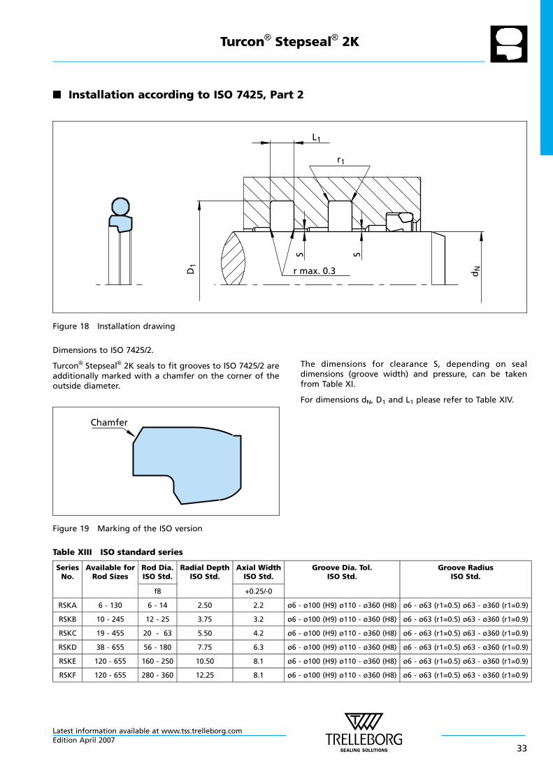
n Installation according to ISO 7425, Part 2
r max. 0.3
r1
L1
SS
D1
dN
Figure 18 Installation drawing
Dimensions to ISO 7425/2.
Turcon® Stepseal® 2K seals to fit grooves to ISO 7425/2 areadditionally marked with a chamfer on the corner of theoutside diameter.
Chamfer
Figure 19 Marking of the ISO version
The dimensions for clearance S, depending on sealdimensions (groove width) and pressure, can be takenfrom Table XI.
For dimensions dN, D1 and L1 please refer to Table XIV.
Table XIII ISO standard series
SeriesNo.
Available forRod Sizes
Rod Dia.ISO Std.
Radial DepthISO Std.
Axial WidthISO Std.
Groove Dia. Tol.ISO Std.
Groove RadiusISO Std.
f8 +0.25/-0
RSKA 6 - 130 6 - 14 2.50 2.2 ø6 - ø100 (H9) ø110 - ø360 (H8) ø6 - ø63 (r1=0.5) ø63 - ø360 (r1=0.9)
RSKB 10 - 245 12 - 25 3.75 3.2 ø6 - ø100 (H9) ø110 - ø360 (H8) ø6 - ø63 (r1=0.5) ø63 - ø360 (r1=0.9)
RSKC 19 - 455 20 - 63 5.50 4.2 ø6 - ø100 (H9) ø110 - ø360 (H8) ø6 - ø63 (r1=0.5) ø63 - ø360 (r1=0.9)
RSKD 38 - 655 56 - 180 7.75 6.3 ø6 - ø100 (H9) ø110 - ø360 (H8) ø6 - ø63 (r1=0.5) ø63 - ø360 (r1=0.9)
RSKE 120 - 655 160 - 250 10.50 8.1 ø6 - ø100 (H9) ø110 - ø360 (H8) ø6 - ø63 (r1=0.5) ø63 - ø360 (r1=0.9)
RSKF 120 - 655 280 - 360 12.25 8.1 ø6 - ø100 (H9) ø110 - ø360 (H8) ø6 - ø63 (r1=0.5) ø63 - ø360 (r1=0.9)
Turcon® Stepseal® 2K
Latest information available at www.tss.trelleborg.comEdition April 2007
33
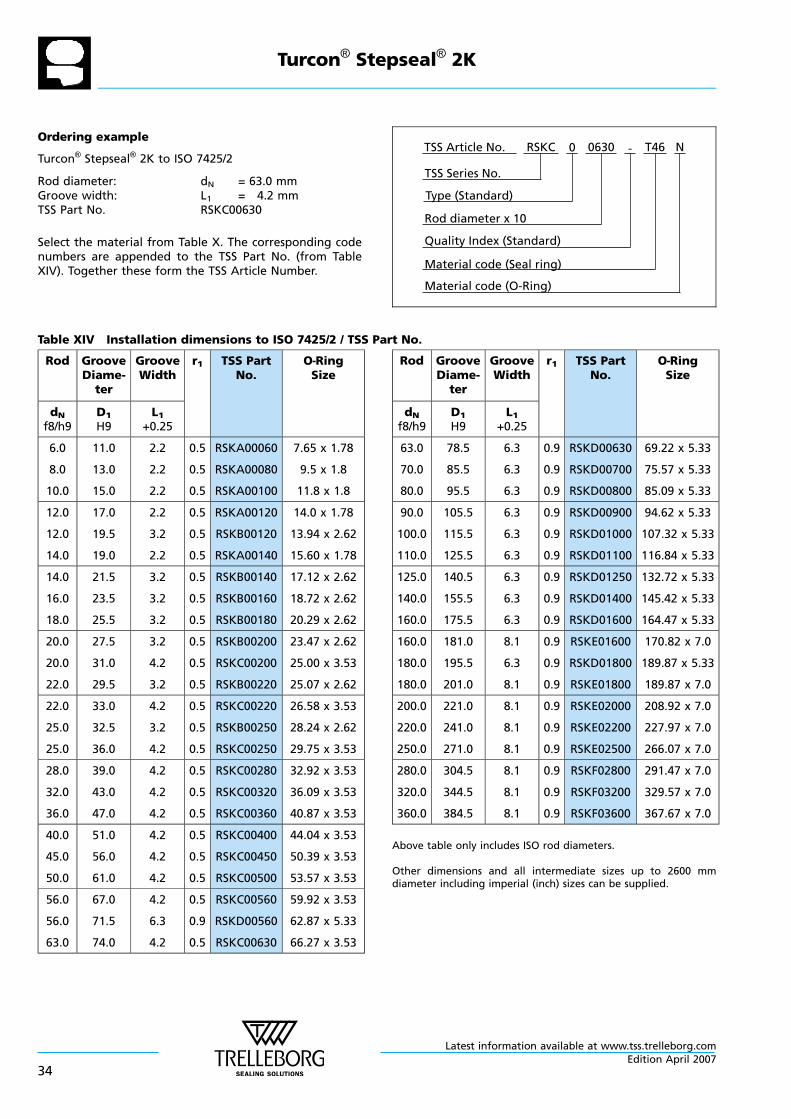
Ordering example
Turcon® Stepseal® 2K to ISO 7425/2
Rod diameter: dN = 63.0 mmGroove width: L1 = 4.2 mmTSS Part No. RSKC00630
Select the material from Table X. The corresponding codenumbers are appended to the TSS Part No. (from TableXIV). Together these form the TSS Article Number.
Material code (Seal ring)
TSS Series No.
TSS Article No. T460630 N
Material code (O-Ring)
Rod diameter x 10
RSKC
Quality Index (Standard)
-
Type (Standard)
0
Table XIV Installation dimensions to ISO 7425/2 / TSS Part No.
Rod GrooveDiame-ter
GrooveWidth
r1 TSS PartNo.
O—RingSize
dNf8/h9
D1H9
L1+0.25
6.0
8.0
10.0
11.0
13.0
15.0
2.2
2.2
2.2
0.5
0.5
0.5
RSKA00060
RSKA00080
RSKA00100
7.65 x 1.78
9.5 x 1.8
11.8 x 1.8
12.0
12.0
14.0
17.0
19.5
19.0
2.2
3.2
2.2
0.5
0.5
0.5
RSKA00120
RSKB00120
RSKA00140
14.0 x 1.78
13.94 x 2.62
15.60 x 1.78
14.0
16.0
18.0
21.5
23.5
25.5
3.2
3.2
3.2
0.5
0.5
0.5
RSKB00140
RSKB00160
RSKB00180
17.12 x 2.62
18.72 x 2.62
20.29 x 2.62
20.0
20.0
22.0
27.5
31.0
29.5
3.2
4.2
3.2
0.5
0.5
0.5
RSKB00200
RSKC00200
RSKB00220
23.47 x 2.62
25.00 x 3.53
25.07 x 2.62
22.0
25.0
25.0
33.0
32.5
36.0
4.2
3.2
4.2
0.5
0.5
0.5
RSKC00220
RSKB00250
RSKC00250
26.58 x 3.53
28.24 x 2.62
29.75 x 3.53
28.0
32.0
36.0
39.0
43.0
47.0
4.2
4.2
4.2
0.5
0.5
0.5
RSKC00280
RSKC00320
RSKC00360
32.92 x 3.53
36.09 x 3.53
40.87 x 3.53
40.0
45.0
50.0
51.0
56.0
61.0
4.2
4.2
4.2
0.5
0.5
0.5
RSKC00400
RSKC00450
RSKC00500
44.04 x 3.53
50.39 x 3.53
53.57 x 3.53
56.0
56.0
63.0
67.0
71.5
74.0
4.2
6.3
4.2
0.5
0.9
0.5
RSKC00560
RSKD00560
RSKC00630
59.92 x 3.53
62.87 x 5.33
66.27 x 3.53
Rod GrooveDiame-ter
GrooveWidth
r1 TSS PartNo.
O—RingSize
dNf8/h9
D1H9
L1+0.25
63.0
70.0
80.0
78.5
85.5
95.5
6.3
6.3
6.3
0.9
0.9
0.9
RSKD00630
RSKD00700
RSKD00800
69.22 x 5.33
75.57 x 5.33
85.09 x 5.33
90.0
100.0
110.0
105.5
115.5
125.5
6.3
6.3
6.3
0.9
0.9
0.9
RSKD00900
RSKD01000
RSKD01100
94.62 x 5.33
107.32 x 5.33
116.84 x 5.33
125.0
140.0
160.0
140.5
155.5
175.5
6.3
6.3
6.3
0.9
0.9
0.9
RSKD01250
RSKD01400
RSKD01600
132.72 x 5.33
145.42 x 5.33
164.47 x 5.33
160.0
180.0
180.0
181.0
195.5
201.0
8.1
6.3
8.1
0.9
0.9
0.9
RSKE01600
RSKD01800
RSKE01800
170.82 x 7.0
189.87 x 5.33
189.87 x 7.0
200.0
220.0
250.0
221.0
241.0
271.0
8.1
8.1
8.1
0.9
0.9
0.9
RSKE02000
RSKE02200
RSKE02500
208.92 x 7.0
227.97 x 7.0
266.07 x 7.0
280.0
320.0
360.0
304.5
344.5
384.5
8.1
8.1
8.1
0.9
0.9
0.9
RSKF02800
RSKF03200
RSKF03600
291.47 x 7.0
329.57 x 7.0
367.67 x 7.0
Above table only includes ISO rod diameters.
Other dimensions and all intermediate sizes up to 2600 mmdiameter including imperial (inch) sizes can be supplied.
Turcon® Stepseal® 2K
Latest information available at www.tss.trelleborg.com
34Edition April 2007
ZURCON® RIMSEAL
- Single Acting -
- Rubber Energised Plastic Faced Seal -
- Material -
- Zurcon® -
Latest information available at www.tss.trelleborg.comEdition April 2007
35

Latest information available at www.tss.trelleborg.com
36Edition April 2007
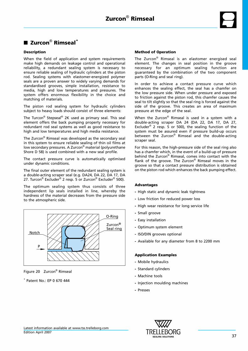
n Zurcon® Rimseal*
Description
When the field of application and system requirementsmake high demands on leakage control and operationalreliability, a redundant sealing system is necessary toensure reliable sealing of hydraulic cylinders at the pistonrod. Sealing systems with elastomer-energized polymerseals are a proven answer to widely varying demands forstandardised grooves, simple installation, resistance tomedia, high and low temperatures and pressures. Thesystem offers enormous flexibility in the choice andmatching of materials.
The piston rod sealing system for hydraulic cylinderssubject to heavy loads should consist of three elements:
The Turcon® Stepseal® 2K used as primary seal. This sealelement offers the back pumping property necessary forredundant rod seal systems as well as good resistance tohigh and low temperatures and high media resistance.
The Zurcon® Rimseal was developed as the secondary sealin this system to ensure reliable sealing of thin oil films atlow secondary pressures. A Zurcon® material (polyurethaneShore D 58) is used combined with a new seal profile.
The contact pressure curve is automatically optimisedunder dynamic conditions.
The final outer element of the redundant sealing system isa double-acting scraper seal (e.g. DA24, DA 22, DA 17, DA27. Turcon® Excluder® 2 resp. 5 or Zurcon® Excluder® 500).
The optimum sealing system thus consists of threeindependent lip seals installed in line, whereby thehardness of the material decreases from the pressure sideto the atmospheric side.
P
O-Ring
Zurcon®
Seal ringNotch
Figure 20 Zurcon® Rimseal
Method of Operation
The Zurcon® Rimseal is an elastomer energised sealelement. The changes in seal position in the groovenecessary for an optimum sealing function areguaranteed by the combination of the two componentparts (O—Ring and seal ring).
In order to achieve a contact pressure curve whichenhances the sealing effect, the seal has a chamfer onthe low pressure side. When under pressure and exposedto friction against the piston rod, this chamfer causes theseal to tilt slightly so that the seal ring is forced against theside of the groove. This creates an area of maximumpressure at the edge of the seal.
When the Zurcon® Rimseal is used in a system with adouble-acting scraper DA 24 (DA 22, DA 17, DA 27,Excluder® 2 resp. 5 or 500), the sealing function of thesystem must be assured even if pressure build-up occursbetween the Zurcon® Rimseal and the double-actingscraper seal.
For this reason, the high-pressure side of the seal ring alsohas a chamfer which, in the event of a build-up of pressurebehind the Zurcon® Rimseal, comes into contact with theflank of the groove. The Zurcon® Rimseal moves in thegroove so that a contact pressure distribution is obtainedon the piston rod which enhances the back pumping effect.
Advantages
- High static and dynamic leak tightness
- Low friction for reduced power loss
- High wear resistance for long service life
- Small groove
- Easy installation
- Optimum system element
- ISO/DIN grooves optional
- Available for any diameter from 8 to 2200 mm
Application Examples
- Mobile hydraulics
- Standard cylinders
- Machine tools
- Injection moulding machines
- Presses
* Patent No.: EP 0 670 444
Zurcon® Rimseal
Latest information available at www.tss.trelleborg.comEdition April 2007
37
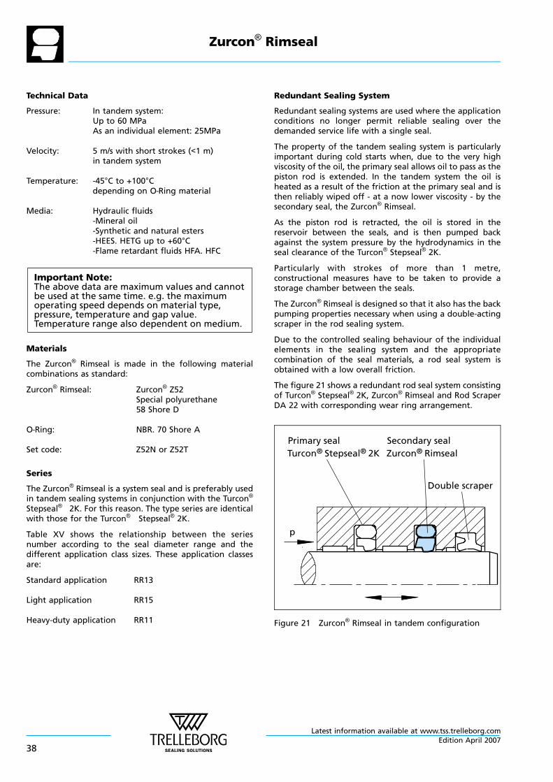
Technical Data
Pressure: In tandem system:Up to 60 MPaAs an individual element: 25MPa
Velocity: 5 m/s with short strokes (<1 m)in tandem system
Temperature: -45°C to +100°Cdepending on O—Ring material
Media: Hydraulic fluids-Mineral oil-Synthetic and natural esters-HEES. HETG up to +60°C-Flame retardant fluids HFA. HFC
Important Note:The above data are maximum values and cannotbe used at the same time. e.g. the maximumoperating speed depends on material type,pressure, temperature and gap value.Temperature range also dependent on medium.
Materials
The Zurcon® Rimseal is made in the following materialcombinations as standard:
Zurcon® Rimseal: Zurcon® Z52Special polyurethane58 Shore D
O—Ring: NBR. 70 Shore A
Set code: Z52N or Z52T
Series
The Zurcon® Rimseal is a system seal and is preferably usedin tandem sealing systems in conjunction with the Turcon®
Stepseal® 2K. For this reason. The type series are identicalwith those for the Turcon® Stepseal® 2K.
Table XV shows the relationship between the seriesnumber according to the seal diameter range and thedifferent application class sizes. These application classesare:
Standard application RR13
Light application RR15
Heavy-duty application RR11
Redundant Sealing System
Redundant sealing systems are used where the applicationconditions no longer permit reliable sealing over thedemanded service life with a single seal.
The property of the tandem sealing system is particularlyimportant during cold starts when, due to the very highviscosity of the oil, the primary seal allows oil to pass as thepiston rod is extended. In the tandem system the oil isheated as a result of the friction at the primary seal and isthen reliably wiped off - at a now lower viscosity - by thesecondary seal, the Zurcon® Rimseal.
As the piston rod is retracted, the oil is stored in thereservoir between the seals, and is then pumped backagainst the system pressure by the hydrodynamics in theseal clearance of the Turcon® Stepseal® 2K.
Particularly with strokes of more than 1 metre,constructional measures have to be taken to provide astorage chamber between the seals.
The Zurcon® Rimseal is designed so that it also has the backpumping properties necessary when using a double-actingscraper in the rod sealing system.
Due to the controlled sealing behaviour of the individualelements in the sealing system and the appropriatecombination of the seal materials, a rod seal system isobtained with a low overall friction.
The figure 21 shows a redundant rod seal system consistingof Turcon® Stepseal® 2K, Zurcon® Rimseal and Rod ScraperDA 22 with corresponding wear ring arrangement.
Double scraper
Turcon® Stepseal® 2KPrimary seal Secondary seal
Zurcon® Rimseal
p
Figure 21 Zurcon® Rimseal in tandem configuration
Zurcon® Rimseal
Latest information available at www.tss.trelleborg.com
38Edition April 2007
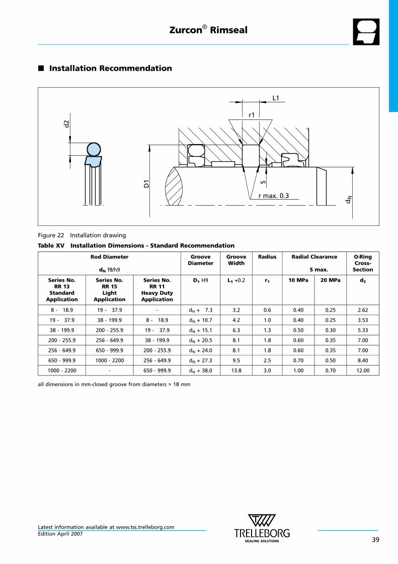
n Installation Recommendation
r1
dN
D1
d2
S
r max. 0.3
L1
Figure 22 Installation drawing
Table XV Installation Dimensions - Standard Recommendation
Rod Diameter
dN f8/h9
GrooveDiameter
GrooveWidth
Radius Radial Clearance
S max.
O—RingCross-Section
Series No.RR 13
StandardApplication
Series No.RR 15Light
Application
Series No.RR 11
Heavy DutyApplication
D1 H9 L1 +0.2 r1 10 MPa 20 MPa d2
8 - 18.9 19 - 37.9 - dN + 7.3 3.2 0.6 0.40 0.25 2.62
19 - 37.9 38 - 199.9 8 - 18.9 dN + 10.7 4.2 1.0 0.40 0.25 3.53
38 - 199.9 200 - 255.9 19 - 37.9 dN + 15.1 6.3 1.3 0.50 0.30 5.33
200 - 255.9 256 - 649.9 38 - 199.9 dN + 20.5 8.1 1.8 0.60 0.35 7.00
256 - 649.9 650 - 999.9 200 - 255.9 dN + 24.0 8.1 1.8 0.60 0.35 7.00
650 - 999.9 1000 - 2200 256 - 649.9 dN + 27.3 9.5 2.5 0.70 0.50 8.40
1000 - 2200 - 650 - 999.9 dN + 38.0 13.8 3.0 1.00 0.70 12.00
all dimensions in mm-closed groove from diameters > 18 mm
Zurcon® Rimseal
Latest information available at www.tss.trelleborg.comEdition April 2007
39
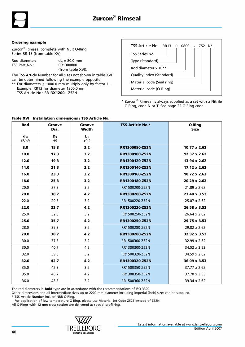
Ordering example
Zurcon® Rimseal complete with NBR O—RingSeries RR 13 (from table XV).
Rod diameter: dN = 80.0 mmTSS Part No.: RR1300800
(from table XVI).
The TSS Article Number for all sizes not shown in table XVIcan be determined following the example opposite.** For diameters 1000.0 mm multiply only by factor 1.
Example: RR13 for diameter 1200.0 mm.TSS Article No.: RR13X1200 - Z52N.
Material code (Seal ring)
TSS Series No.
TSS Article No. Z520800 N*
Material code (O-Ring)
Rod diameter x 10**
RR13
Quality Index (Standard)
-
Type (Standard)
0
* Zurcon® Rimseal is always supplied as a set with a NitrileO—Ring, code N or T. See page 22 O—Ring code.
Table XVI Installation dimensions / TSS Article No.
Rod GrooveDia.
GrooveWidth
TSS Article No.* O—RingSize
dNf8/h9
D1H9
L1+0.2
8.0
10.0
12.0
15.3
17.3
19.3
3.2
3.2
3.2
RR1300080-Z52N
RR1300100-Z52N
RR1300120-Z52N
10.77 x 2.62
12.37 x 2.62
13.94 x 2.62
14.0
16.0
18.0
21.3
23.3
25.3
3.2
3.2
3.2
RR1300140-Z52N
RR1300160-Z52N
RR1300180-Z52N
17.12 x 2.62
18.72 x 2.62
20.29 x 2.62
20.0
20.0
22.0
27.3
30.7
29.3
3.2
4.2
3.2
RR1500200-Z52N
RR1300200-Z52N
RR1500220-Z52N
21.89 x 2.62
23.40 x 3.53
25.07 x 2.62
22.0
25.0
25.0
32.7
32.3
35.7
4.2
3.2
4.2
RR1300220-Z52N
RR1500250-Z52N
RR1300250-Z52N
26.58 x 3.53
26.64 x 2.62
29.75 x 3.53
28.0
28.0
30.0
35.3
38.7
37.3
3.2
4.2
3.2
RR1500280-Z52N
RR1300280-Z52N
RR1500300-Z52N
29.82 x 2.62
32.92 x 3.53
32.99 x 2.62
30.0
32.0
32.0
40.7
39.3
42.7
4.2
3.2
4.2
RR1300300-Z52N
RR1500320-Z52N
RR1300320-Z52N
34.52 x 3.53
34.59 x 2.62
36.09 x 3.53
35.0
35.0
36.0
42.3
45.7
43.3
3.2
4.2
3.2
RR1500350-Z52N
RR1300350-Z52N
RR1500360-Z52N
37.77 x 2.62
37.70 x 3.53
39.34 x 2.62
The rod diameters in bold type are in accordance with the recommendations of ISO 3320.Other dimensions and all intermediate sizes up to 2200 mm diameter including imperial (inch) sizes can be supplied.* TSS Article Number incl. of NBR-O—Ring.For application of low-temperature O—Ring, please use Material Set Code Z52T instead of Z52N
All O—Rings with 12 mm cross section are delivered as special profilring.
Zurcon® Rimseal
Latest information available at www.tss.trelleborg.com
40Edition April 2007
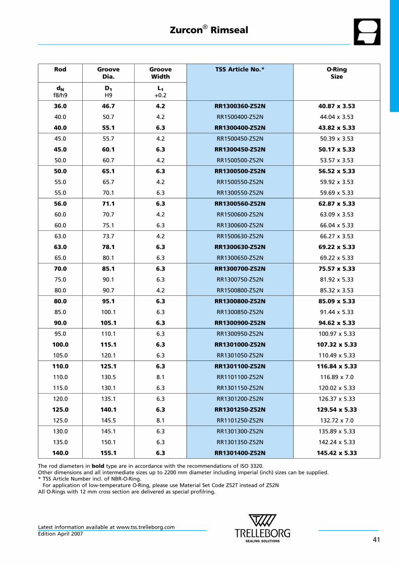
Rod GrooveDia.
GrooveWidth
TSS Article No.* O—RingSize
dNf8/h9
D1H9
L1+0.2
36.0
40.0
40.0
46.7
50.7
55.1
4.2
4.2
6.3
RR1300360-Z52N
RR1500400-Z52N
RR1300400-Z52N
40.87 x 3.53
44.04 x 3.53
43.82 x 5.33
45.0
45.0
50.0
55.7
60.1
60.7
4.2
6.3
4.2
RR1500450-Z52N
RR1300450-Z52N
RR1500500-Z52N
50.39 x 3.53
50.17 x 5.33
53.57 x 3.53
50.0
55.0
55.0
65.1
65.7
70.1
6.3
4.2
6.3
RR1300500-Z52N
RR1500550-Z52N
RR1300550-Z52N
56.52 x 5.33
59.92 x 3.53
59.69 x 5.33
56.0
60.0
60.0
71.1
70.7
75.1
6.3
4.2
6.3
RR1300560-Z52N
RR1500600-Z52N
RR1300600-Z52N
62.87 x 5.33
63.09 x 3.53
66.04 x 5.33
63.0
63.0
65.0
73.7
78.1
80.1
4.2
6.3
6.3
RR1500630-Z52N
RR1300630-Z52N
RR1300650-Z52N
66.27 x 3.53
69.22 x 5.33
69.22 x 5.33
70.0
75.0
80.0
85.1
90.1
90.7
6.3
6.3
4.2
RR1300700-Z52N
RR1300750-Z52N
RR1500800-Z52N
75.57 x 5.33
81.92 x 5.33
85.32 x 3.53
80.0
85.0
90.0
95.1
100.1
105.1
6.3
6.3
6.3
RR1300800-Z52N
RR1300850-Z52N
RR1300900-Z52N
85.09 x 5.33
91.44 x 5.33
94.62 x 5.33
95.0
100.0
105.0
110.1
115.1
120.1
6.3
6.3
6.3
RR1300950-Z52N
RR1301000-Z52N
RR1301050-Z52N
100.97 x 5.33
107.32 x 5.33
110.49 x 5.33
110.0
110.0
115.0
125.1
130.5
130.1
6.3
8.1
6.3
RR1301100-Z52N
RR1101100-Z52N
RR1301150-Z52N
116.84 x 5.33
116.89 x 7.0
120.02 x 5.33
120.0
125.0
125.0
135.1
140.1
145.5
6.3
6.3
8.1
RR1301200-Z52N
RR1301250-Z52N
RR1101250-Z52N
126.37 x 5.33
129.54 x 5.33
132.72 x 7.0
130.0
135.0
140.0
145.1
150.1
155.1
6.3
6.3
6.3
RR1301300-Z52N
RR1301350-Z52N
RR1301400-Z52N
135.89 x 5.33
142.24 x 5.33
145.42 x 5.33
The rod diameters in bold type are in accordance with the recommendations of ISO 3320.Other dimensions and all intermediate sizes up to 2200 mm diameter including imperial (inch) sizes can be supplied.* TSS Article Number incl. of NBR-O—Ring.For application of low-temperature O—Ring, please use Material Set Code Z52T instead of Z52N
All O—Rings with 12 mm cross section are delivered as special profilring.
Zurcon® Rimseal
Latest information available at www.tss.trelleborg.comEdition April 2007
41
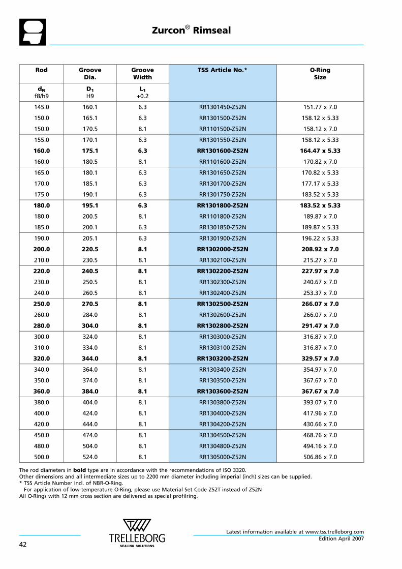
Rod GrooveDia.
GrooveWidth
TSS Article No.* O—RingSize
dNf8/h9
D1H9
L1+0.2
145.0
150.0
150.0
160.1
165.1
170.5
6.3
6.3
8.1
RR1301450-Z52N
RR1301500-Z52N
RR1101500-Z52N
151.77 x 7.0
158.12 x 5.33
158.12 x 7.0
155.0
160.0
160.0
170.1
175.1
180.5
6.3
6.3
8.1
RR1301550-Z52N
RR1301600-Z52N
RR1101600-Z52N
158.12 x 5.33
164.47 x 5.33
170.82 x 7.0
165.0
170.0
175.0
180.1
185.1
190.1
6.3
6.3
6.3
RR1301650-Z52N
RR1301700-Z52N
RR1301750-Z52N
170.82 x 5.33
177.17 x 5.33
183.52 x 5.33
180.0
180.0
185.0
195.1
200.5
200.1
6.3
8.1
6.3
RR1301800-Z52N
RR1101800-Z52N
RR1301850-Z52N
183.52 x 5.33
189.87 x 7.0
189.87 x 5.33
190.0
200.0
210.0
205.1
220.5
230.5
6.3
8.1
8.1
RR1301900-Z52N
RR1302000-Z52N
RR1302100-Z52N
196.22 x 5.33
208.92 x 7.0
215.27 x 7.0
220.0
230.0
240.0
240.5
250.5
260.5
8.1
8.1
8.1
RR1302200-Z52N
RR1302300-Z52N
RR1302400-Z52N
227.97 x 7.0
240.67 x 7.0
253.37 x 7.0
250.0
260.0
280.0
270.5
284.0
304.0
8.1
8.1
8.1
RR1302500-Z52N
RR1302600-Z52N
RR1302800-Z52N
266.07 x 7.0
266.07 x 7.0
291.47 x 7.0
300.0
310.0
320.0
324.0
334.0
344.0
8.1
8.1
8.1
RR1303000-Z52N
RR1303100-Z52N
RR1303200-Z52N
316.87 x 7.0
316.87 x 7.0
329.57 x 7.0
340.0
350.0
360.0
364.0
374.0
384.0
8.1
8.1
8.1
RR1303400-Z52N
RR1303500-Z52N
RR1303600-Z52N
354.97 x 7.0
367.67 x 7.0
367.67 x 7.0
380.0
400.0
420.0
404.0
424.0
444.0
8.1
8.1
8.1
RR1303800-Z52N
RR1304000-Z52N
RR1304200-Z52N
393.07 x 7.0
417.96 x 7.0
430.66 x 7.0
450.0
480.0
500.0
474.0
504.0
524.0
8.1
8.1
8.1
RR1304500-Z52N
RR1304800-Z52N
RR1305000-Z52N
468.76 x 7.0
494.16 x 7.0
506.86 x 7.0
The rod diameters in bold type are in accordance with the recommendations of ISO 3320.Other dimensions and all intermediate sizes up to 2200 mm diameter including imperial (inch) sizes can be supplied.* TSS Article Number incl. of NBR-O—Ring.For application of low-temperature O—Ring, please use Material Set Code Z52T instead of Z52N
All O—Rings with 12 mm cross section are delivered as special profilring.
Zurcon® Rimseal
Latest information available at www.tss.trelleborg.com
42Edition April 2007

Rod GrooveDia.
GrooveWidth
TSS Article No.* O—RingSize
dNf8/h9
D1H9
L1+0.2
600.0
610.0
620.0
624.0
634.0
644.0
8.1
8.1
8.1
RR1306000-Z52N
RR1306100-Z52N
RR1306200-Z52N
608.08 x 7.0
633.48 x 7.0
633.48 x 7.0
630.0
640.0
650.0
654.0
664.0
677.3
8.1
8.1
9.5
RR1306300-Z52N
RR1306400-Z52N
RR1306500-Z52N
658.88 x 7.0
658.88 x 7.0
663 x 8.4
656.0
660.0
680.0
683.3
687.3
707.3
9.5
9.5
9.5
RR1306560-Z52N
RR1306600-Z52N
RR1306800-Z52N
669 x 8.4
673 x 8.4
693 x 8.4
685.0
700.0
700.0
712.3
724.0
727.3
9.5
8.1
9.5
RR1306850-Z52N
RR1507000-Z52N
RR1307000-Z52N
698 x 8.4
712 x 7.0
713 x 8.4
710.0
730.0
760.0
737.3
757.3
787.3
9.5
9.5
9.5
RR1307100-Z52N
RR1307300-Z52N
RR1307600-Z52N
723 x 8.4
743 x 8.4
773 x 8.4
765.0
780.0
790.0
792.3
807.3
817.3
9.5
9.5
9.5
RR1307650-Z52N
RR1307800-Z52N
RR1307900-Z52N
778 x 8.4
793 x 8.4
803 x 8.4
800.0
810.0
820.0
827.3
837.3
847.3
9.5
9.5
9.5
RR1308000-Z52N
RR1308100-Z52N
RR1308200-Z52N
813 x 8.4
823 x 8.4
833 x 8.4
830.0
850.0
870.0
857.3
877.3
897.3
9.5
9.5
9.5
RR1308300-Z52N
RR1308500-Z52N
RR1308700-Z52N
843 x 8.4
863 x 8.4
883 x 8.4
880.0
885.0
890.0
907.3
912.3
917.3
9.5
9.5
9.5
RR1308800-Z52N
RR1308850-Z52N
RR1308900-Z52N
893 x 8.4
898 x 8.4
903 x 8.4
930.0
955.0
1000.0
957.3
982.3
1038.0
9.5
9.5
13.8
RR1309300-Z52N
RR1309550-Z52N
RR13X1000-Z52N
943 x 8.4
968 x 8.4
1016 x 12
1035.0
1040.0
1040.0
1073.0
1067.3
1078.0
13.8
9.5
13.8
RR13X1035-Z52N
RR15X1040-Z52N
RR13X1040-Z52N
1051 x 12
1053 x 8.4
1056 x 12
The rod diameters in bold type are in accordance with the recommendations of ISO 3320.Other dimensions and all intermediate sizes up to 2200 mm diameter including imperial (inch) sizes can be supplied.* TSS Article Number incl. of NBR-O—Ring.For application of low-temperature O—Ring, please use Material Set Code Z52T instead of Z52N
All O—Rings with 12 mm cross section are delivered as special profilring.
Zurcon® Rimseal
Latest information available at www.tss.trelleborg.comEdition April 2007
43
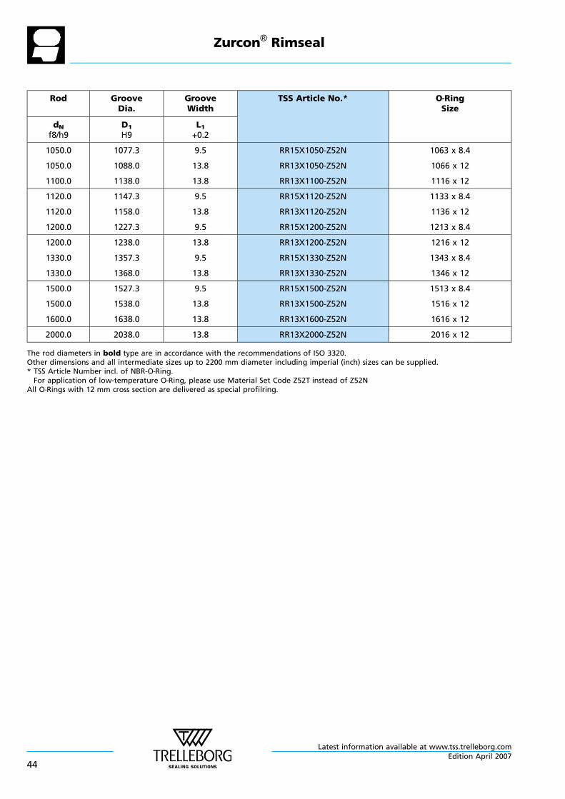
Rod GrooveDia.
GrooveWidth
TSS Article No.* O—RingSize
dNf8/h9
D1H9
L1+0.2
1050.0
1050.0
1100.0
1077.3
1088.0
1138.0
9.5
13.8
13.8
RR15X1050-Z52N
RR13X1050-Z52N
RR13X1100-Z52N
1063 x 8.4
1066 x 12
1116 x 12
1120.0
1120.0
1200.0
1147.3
1158.0
1227.3
9.5
13.8
9.5
RR15X1120-Z52N
RR13X1120-Z52N
RR15X1200-Z52N
1133 x 8.4
1136 x 12
1213 x 8.4
1200.0
1330.0
1330.0
1238.0
1357.3
1368.0
13.8
9.5
13.8
RR13X1200-Z52N
RR15X1330-Z52N
RR13X1330-Z52N
1216 x 12
1343 x 8.4
1346 x 12
1500.0
1500.0
1600.0
1527.3
1538.0
1638.0
9.5
13.8
13.8
RR15X1500-Z52N
RR13X1500-Z52N
RR13X1600-Z52N
1513 x 8.4
1516 x 12
1616 x 12
2000.0 2038.0 13.8 RR13X2000-Z52N 2016 x 12
The rod diameters in bold type are in accordance with the recommendations of ISO 3320.Other dimensions and all intermediate sizes up to 2200 mm diameter including imperial (inch) sizes can be supplied.* TSS Article Number incl. of NBR-O—Ring.For application of low-temperature O—Ring, please use Material Set Code Z52T instead of Z52N
All O—Rings with 12 mm cross section are delivered as special profilring.
Zurcon® Rimseal
Latest information available at www.tss.trelleborg.com
44Edition April 2007
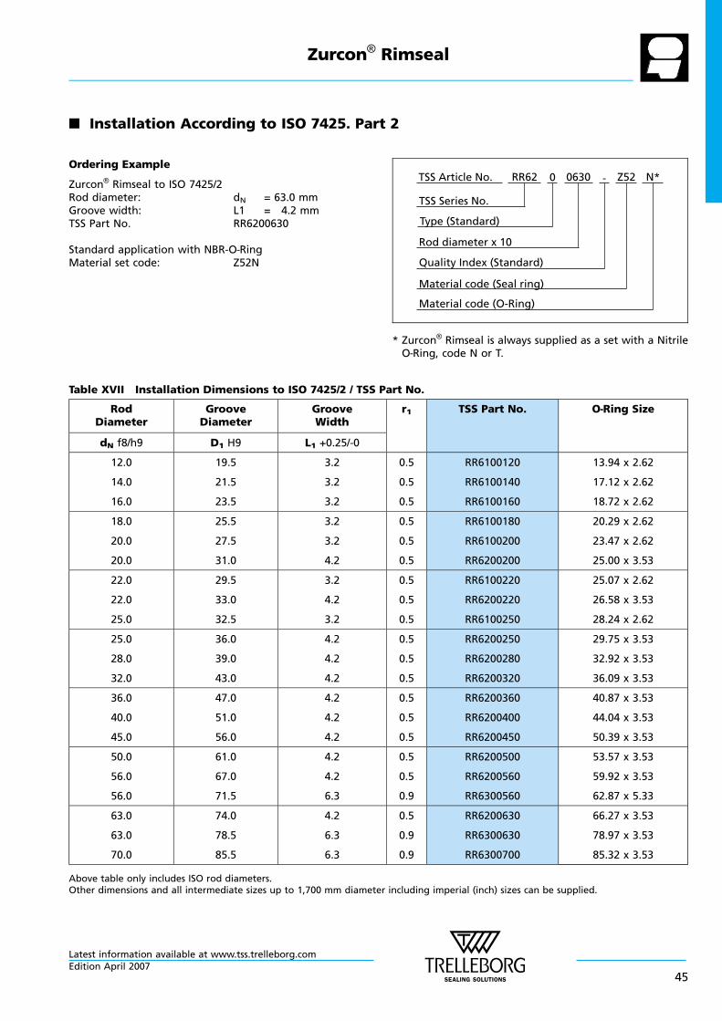
n Installation According to ISO 7425. Part 2
Ordering Example
Zurcon® Rimseal to ISO 7425/2Rod diameter: dN = 63.0 mmGroove width: L1 = 4.2 mmTSS Part No. RR6200630
Standard application with NBR-O—RingMaterial set code: Z52N
Material code (Seal ring)
TSS Series No.
TSS Article No. Z520630 N*
Material code (O-Ring)
Rod diameter x 10
RR62
Quality Index (Standard)
-
Type (Standard)
0
* Zurcon® Rimseal is always supplied as a set with a NitrileO—Ring, code N or T.
Table XVII Installation Dimensions to ISO 7425/2 / TSS Part No.
RodDiameter
GrooveDiameter
GrooveWidth
r1 TSS Part No. O—Ring Size
dN f8/h9 D1 H9 L1 +0.25/-0
12.0
14.0
16.0
19.5
21.5
23.5
3.2
3.2
3.2
0.5
0.5
0.5
RR6100120
RR6100140
RR6100160
13.94 x 2.62
17.12 x 2.62
18.72 x 2.62
18.0
20.0
20.0
25.5
27.5
31.0
3.2
3.2
4.2
0.5
0.5
0.5
RR6100180
RR6100200
RR6200200
20.29 x 2.62
23.47 x 2.62
25.00 x 3.53
22.0
22.0
25.0
29.5
33.0
32.5
3.2
4.2
3.2
0.5
0.5
0.5
RR6100220
RR6200220
RR6100250
25.07 x 2.62
26.58 x 3.53
28.24 x 2.62
25.0
28.0
32.0
36.0
39.0
43.0
4.2
4.2
4.2
0.5
0.5
0.5
RR6200250
RR6200280
RR6200320
29.75 x 3.53
32.92 x 3.53
36.09 x 3.53
36.0
40.0
45.0
47.0
51.0
56.0
4.2
4.2
4.2
0.5
0.5
0.5
RR6200360
RR6200400
RR6200450
40.87 x 3.53
44.04 x 3.53
50.39 x 3.53
50.0
56.0
56.0
61.0
67.0
71.5
4.2
4.2
6.3
0.5
0.5
0.9
RR6200500
RR6200560
RR6300560
53.57 x 3.53
59.92 x 3.53
62.87 x 5.33
63.0
63.0
70.0
74.0
78.5
85.5
4.2
6.3
6.3
0.5
0.9
0.9
RR6200630
RR6300630
RR6300700
66.27 x 3.53
78.97 x 3.53
85.32 x 3.53
Above table only includes ISO rod diameters.Other dimensions and all intermediate sizes up to 1,700 mm diameter including imperial (inch) sizes can be supplied.
Zurcon® Rimseal
Latest information available at www.tss.trelleborg.comEdition April 2007
45
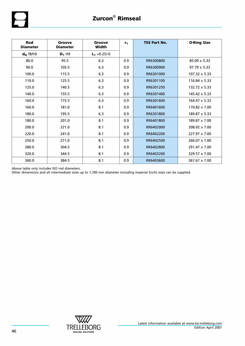
RodDiameter
GrooveDiameter
GrooveWidth
r1 TSS Part No. O—Ring Size
dN f8/h9 D1 H9 L1 +0.25/-0
80.0
90.0
100.0
95.5
105.5
115.5
6.3
6.3
6.3
0.9
0.9
0.9
RR6300800
RR6300900
RR6301000
85.09 x 5.33
97.79 x 5.33
107.32 x 5.33
110.0
125.0
140.0
125.5
140.5
155.5
6.3
6.3
6.3
0.9
0.9
0.9
RR6301100
RR6301250
RR6301400
116.84 x 5.33
132.72 x 5.33
145.42 x 5.33
160.0
160.0
180.0
175.5
181.0
195.5
6.3
8.1
6.3
0.9
0.9
0.9
RR6301600
RR6401600
RR6301800
164.47 x 5.33
170.82 x 7.00
189.87 x 5.33
180.0
200.0
220.0
201.0
221.0
241.0
8.1
8.1
8.1
0.9
0.9
0.9
RR6401800
RR6402000
RR6402200
189.87 x 7.00
208.92 x 7.00
227.97 x 7.00
250.0
280.0
320.0
271.0
304.5
344.5
8.1
8.1
8.1
0.9
0.9
0.9
RR6402500
RR6402800
RR6403200
266.07 x 7.00
291.47 x 7.00
329.57 x 7.00
360.0 384.5 8.1 0.9 RR6403600 367.67 x 7.00
Above table only includes ISO rod diameters.Other dimensions and all intermediate sizes up to 1,700 mm diameter including imperial (inch) sizes can be supplied.
Zurcon® Rimseal
Latest information available at www.tss.trelleborg.com
46Edition April 2007
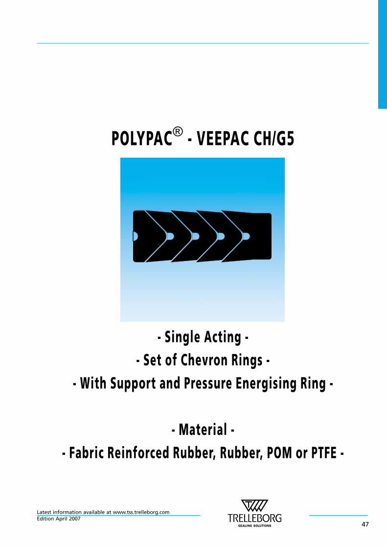
POLYPAC® - VEEPAC CH/G5
- Single Acting -
- Set of Chevron Rings -
- With Support and Pressure Energising Ring -
- Material -
- Fabric Reinforced Rubber, Rubber, POM or PTFE -
Latest information available at www.tss.trelleborg.comEdition April 2007
47

Latest information available at www.tss.trelleborg.com
48Edition April 2007
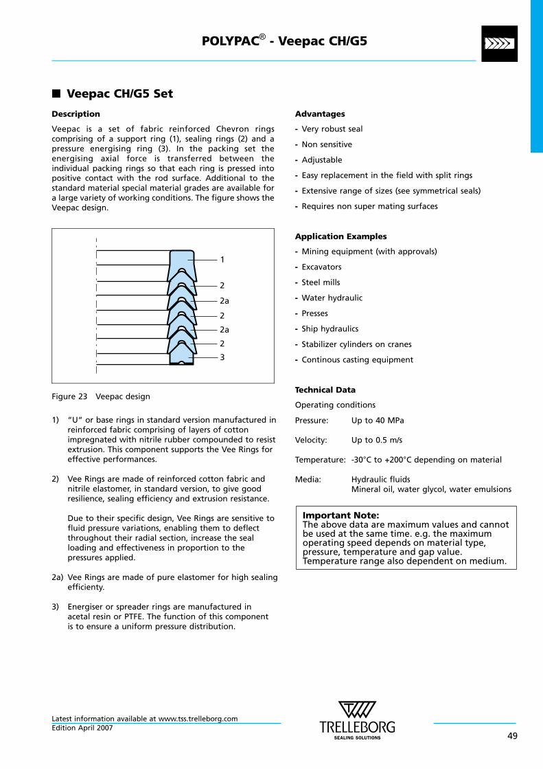
n Veepac CH/G5 Set
Description
Veepac is a set of fabric reinforced Chevron ringscomprising of a support ring (1), sealing rings (2) and apressure energising ring (3). In the packing set theenergising axial force is transferred between theindividual packing rings so that each ring is pressed intopositive contact with the rod surface. Additional to thestandard material special material grades are available fora large variety of working conditions. The figure shows theVeepac design.
1
3
2
2a
2
2a
2
Figure 23 Veepac design
1) “U“ or base rings in standard version manufactured inreinforced fabric comprising of layers of cottonimpregnated with nitrile rubber compounded to resistextrusion. This component supports the Vee Rings foreffective performances.
2) Vee Rings are made of reinforced cotton fabric andnitrile elastomer, in standard version, to give goodresilience, sealing efficiency and extrusion resistance.
Due to their specific design, Vee Rings are sensitive tofluid pressure variations, enabling them to deflectthroughout their radial section, increase the sealloading and effectiveness in proportion to thepressures applied.
2a) Vee Rings are made of pure elastomer for high sealingefficienty.
3) Energiser or spreader rings are manufactured inacetal resin or PTFE. The function of this componentis to ensure a uniform pressure distribution.
Advantages
- Very robust seal
- Non sensitive
- Adjustable
- Easy replacement in the field with split rings
- Extensive range of sizes (see symmetrical seals)
- Requires non super mating surfaces
Application Examples
- Mining equipment (with approvals)
- Excavators
- Steel mills
- Water hydraulic
- Presses
- Ship hydraulics
- Stabilizer cylinders on cranes
- Continous casting equipment
Technical Data
Operating conditions
Pressure: Up to 40 MPa
Velocity: Up to 0.5 m/s
Temperature: -30°C to +200°C depending on material
Media: Hydraulic fluidsMineral oil, water glycol, water emulsions
Important Note:The above data are maximum values and cannotbe used at the same time. e.g. the maximumoperating speed depends on material type,pressure, temperature and gap value.Temperature range also dependent on medium.
POLYPAC® - Veepac CH/G5
Latest information available at www.tss.trelleborg.comEdition April 2007
49
Materials
The following material combination can be supplied:
Standard Non standard Non standard
Material Code N0ONC V0PVA V0PVC
Vee—RingsandBack-up Ring
CottonFabricNBR
AramidFabricFKM
CottonFabricFKM
Spreader* POM PTFE PTFE
ElastomericVee Rings
NBR FKM FKM
TemperatureRange °C
-30+130
-20+200
-20+150
* The material for the spreader is depending from the diameter
Design Instructions
Lead in chamfers
In order to avoid damage to the Veepac during installation,lead in chamfers of min. 5 x 20° must be provided on therods.
Rod Diameter Lead in Chamfer
0 - 100 5 x 20°
101 - 200 7 x 20°
201 - 400 10 x 20°
Surface roughness
Parameter Mating Surfaceµm
Groove Surfaceµm
Rmax 1.00 - 4.00 < 16.0
Rz DIN 0.63 - 2.50 < 10.0
Ra 0.10 - 0.40 < 1.6
The material contact area Rmr should be approx. 50 to 70%,determined at a cut depth c = 0.25 x Rz, relative to areference line of Cref. 5%.
Clearance
The gap behind the seal should not be larger than 0.30 mmin diameter.
POLYPAC® - Veepac CH/G5
Latest information available at www.tss.trelleborg.com
50Edition April 2007
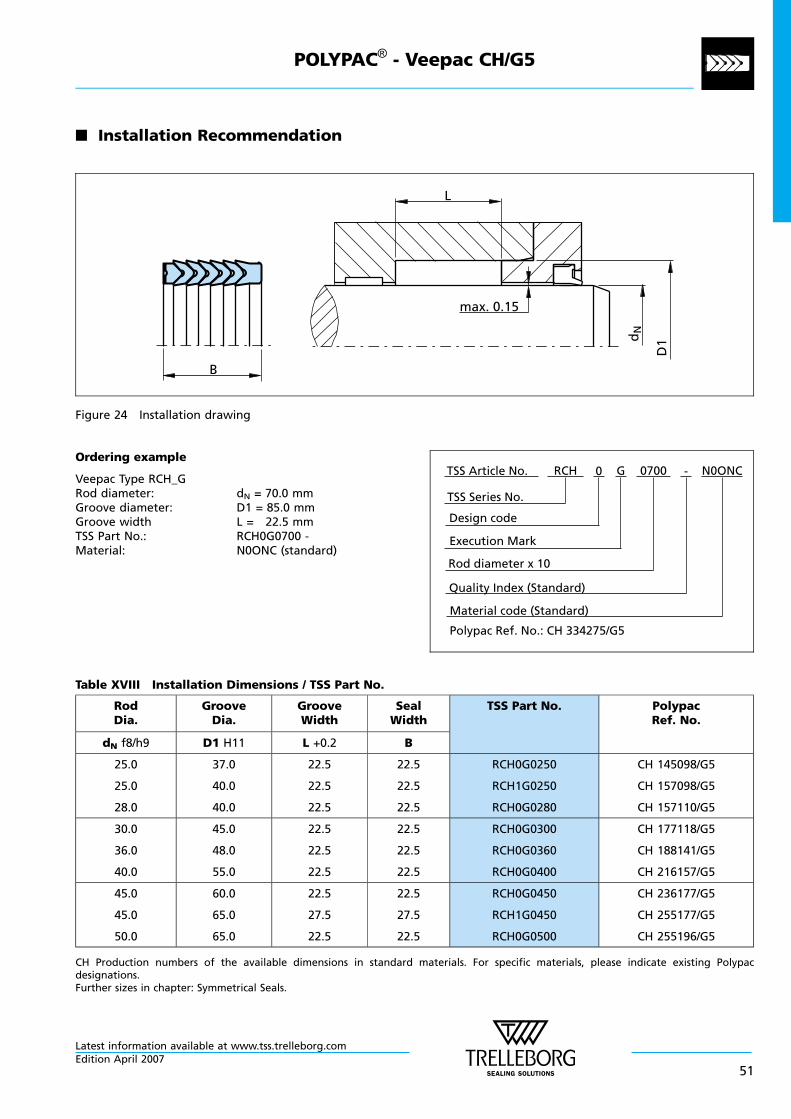
n Installation Recommendation
B
L
D1d
N
max. 0.15
Figure 24 Installation drawing
Ordering example
Veepac Type RCH_GRod diameter: dN = 70.0 mmGroove diameter: D1 = 85.0 mmGroove width L = 22.5 mmTSS Part No.: RCH0G0700 -Material: N0ONC (standard)
Material code (Standard)
TSS Series No.
TSS Article No. N0ONCG
Rod diameter x 10
RCH
Quality Index (Standard)
0700
Design code
0
Execution Mark
-
Polypac Ref. No.: CH 334275/G5
Table XVIII Installation Dimensions / TSS Part No.
RodDia.
GrooveDia.
GrooveWidth
SealWidth
TSS Part No. PolypacRef. No.
dN f8/h9 D1 H11 L +0.2 B
25.0
25.0
28.0
37.0
40.0
40.0
22.5
22.5
22.5
22.5
22.5
22.5
RCH0G0250
RCH1G0250
RCH0G0280
CH 145098/G5
CH 157098/G5
CH 157110/G5
30.0
36.0
40.0
45.0
48.0
55.0
22.5
22.5
22.5
22.5
22.5
22.5
RCH0G0300
RCH0G0360
RCH0G0400
CH 177118/G5
CH 188141/G5
CH 216157/G5
45.0
45.0
50.0
60.0
65.0
65.0
22.5
27.5
22.5
22.5
27.5
22.5
RCH0G0450
RCH1G0450
RCH0G0500
CH 236177/G5
CH 255177/G5
CH 255196/G5
CH Production numbers of the available dimensions in standard materials. For specific materials, please indicate existing Polypacdesignations.Further sizes in chapter: Symmetrical Seals.
POLYPAC® - Veepac CH/G5
Latest information available at www.tss.trelleborg.comEdition April 2007
51
RodDia.
GrooveDia.
GrooveWidth
SealWidth
TSS Part No. PolypacRef. No.
dN f8/h9 D1 H11 L +0.2 B
56.0
60.0
65.0
71.0
80.0
85.0
22.5
37.0
40.0
22.5
37.0
40.0
RCH0G0560
RCH0G0600
RCH0G0650
CH 279220/G5
CH 314236/G5
CH 334255/G5
70.0
70.0
75.0
85.0
90.0
90.0
22.5
40.0
22.5
22.5
40.0
22.5
RCH0G0700
RCH1G0700
RCH0G0750
CH 334275/G5
CH 354275/G5
CH 354295/G5
80.0
80.0
85.0
95.0
100.0
100.0
22.5
40.0
22.5
22.5
40.0
22.5
RCH0G0800
RCH1G0800
RCH0G0850
CH 374314/G5
CH 393314/G5
CH 393334/G5
90.0
90.0
100.0
105.0
110.0
115.0
22.5
40.0
30.0
22.5
40.0
30.0
RCH0G0900
RCH1G0900
RCH0G1000
CH 413354/G5
CH 433354/G5
CH 452393/G5
100.0
110.0
110.0
120.0
125.0
130.0
40.0
30.0
40.0
40.0
30.0
40.0
RCH1G1000
RCH0G1100
RCH1G1100
CH 472393/G5
CH 492433/G5
CH 511433/G5
120.0
125.0
125.0
145.0
140.0
150.0
50.0
34.0
46.0
50.0
34.0
46.0
RCH0G1200
RCH0G1250
RCH1G1250
CH 570472/G5
CH 551492/G5
CH 590492/G5
140.0
140.0
160.0
155.0
165.0
180.0
34.0
46.0
40.0
34.0
46.0
40.0
RCH0G1400
RCH1G1400
RCH0G1600
CH 610551/G5
CH 649551/G5
CH 708629/G5
160.0 190.0 60.0 60.0 RCH1G1600 CH 748629/G5
CH Production numbers of the available dimensions in standard materials. For specific materials, please indicate existing Polypacdesignations.Further sizes in chapter: Symmetrical Seals.
POLYPAC® - Veepac CH/G5
Latest information available at www.tss.trelleborg.com
52Edition April 2007
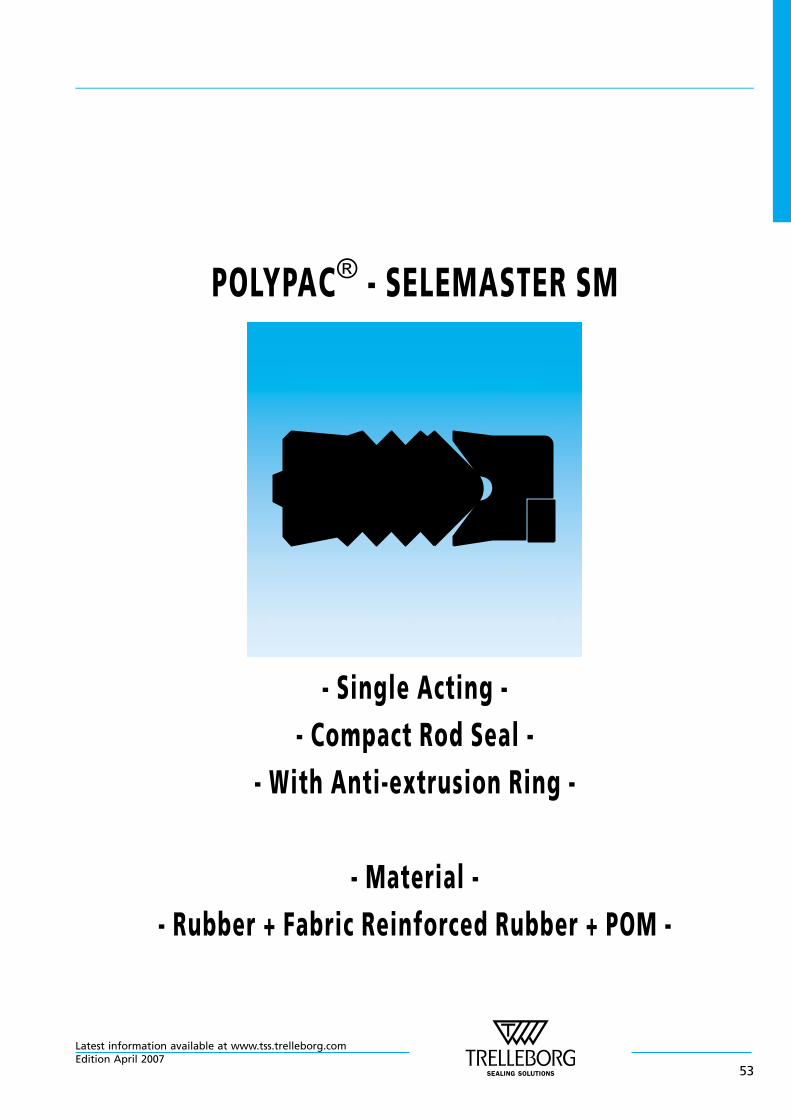
POLYPAC® - SELEMASTER SM
- Single Acting -
- Compact Rod Seal -
- With Anti-extrusion Ring -
- Material -
- Rubber + Fabric Reinforced Rubber + POM -
Latest information available at www.tss.trelleborg.comEdition April 2007
53

Latest information available at www.tss.trelleborg.com
54Edition April 2007
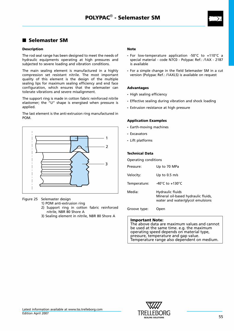
n Selemaster SM
Description
The rod seal range has been designed to meet the needs ofhydraulic equipments operating at high pressures andsubjected to severe loading and vibration conditions.
The main sealing element is manufactured in a highlycompression set resistant nitrile. The most importantquality of this element is the design of the multiplesealing lips for maximum sealing efficiency and end faceconfiguration, which ensures that the selemaster cantolerate vibrations and severe misalignment.
The support ring is made in cotton fabric reinforced nitrileelastomer; the “U“ shape is energised when pressure isapplied.
The last element is the anti-extrusion ring manufactured inPOM.
1
2
3
Figure 25 Selemaster design1) POM anti-extrusion ring2) Support ring in cotton fabric reinforced
nitrile, NBR 80 Shore A3) Sealing element in nitrile, NBR 80 Shore A
Note
- For low-temperature application -50°C to +110°C aspecial material - code N7C0 - Polypac Ref.: /1AX - 2187is available
- For a simple change in the field Selemaster SM in a cutversion (Polypac Ref.: /1AXLS) is available on request
Advantages
- High sealing efficiency
- Effective sealing during vibration and shock loading
- Extrusion resistance at high pressure
Application Examples
- Earth-moving machines
- Excavators
- Lift platforms
Technical Data
Operating conditions
Pressure: Up to 70 MPa
Velocity: Up to 0.5 m/s
Temperature: -40°C to +130°C
Media: Hydraulic fluidsMineral oil-based hydraulic fluids,water and water/glycol emulsions
Groove type: Open
Important Note:The above data are maximum values and cannotbe used at the same time. e.g. the maximumoperating speed depends on material type,pressure, temperature and gap value.Temperature range also dependent on medium.
POLYPAC® - Selemaster SM
Latest information available at www.tss.trelleborg.comEdition April 2007
55
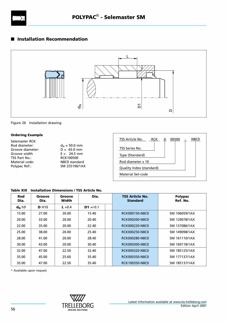
n Installation Recommendation
L
dN D1
D
Figure 26 Installation drawing
Ordering Example
Selemaster RCKRod diameter: dN = 50.0 mmGroove diameter: D = 65.0 mmGroove width E = 24.5 mmTSS Part No.: RCK100500Material code: N8C0 standardPolypac Ref.: SM 255196/1AX
Material Set-code
TSS Series No.
TSS Article No. N8C0
Rod diameter x 10
RCK
Quality Index (standard)
-
Type (Standard)
0 00500
Table XIX Installation Dimensions / TSS Article No.
RodDia.
GrooveDia.
GrooveWidth
Dia. TSS Article No.Standard
PolypacRef. No.
dN h9 D H10 L +0.4 D1 +/-0.1
15.00
20.00
22.00
27.00
33.00
35.00
20.00
20.00
20.00
15.40
20.40
22.40
RCK000150-N8C0
RCK000200-N8C0
RCK000220-N8C0
SM 106059/1AX
SM 129078/1AX
SM 137086/1AX
25.00
28.00
30.00
38.00
41.00
43.00
20.00
20.00
20.00
25.40
28.40
30.40
RCK000250-N8C0
RCK000280-N8C0
RCK000300-N8C0
SM 149098/1AX
SM 161110/1AX
SM 169118/1AX
32.00
35.00
35.00
47.00
45.00
47.00
22.50
25.60
22.50
32.40
35.40
35.40
RCK000320-N8C0
RCK000350-N8C0
RCK100350-N8C0
SM 185125/1AX
SM 177137/1AX
SM 185137/1AX
^ Available upon request
POLYPAC® - Selemaster SM
Latest information available at www.tss.trelleborg.com
56Edition April 2007
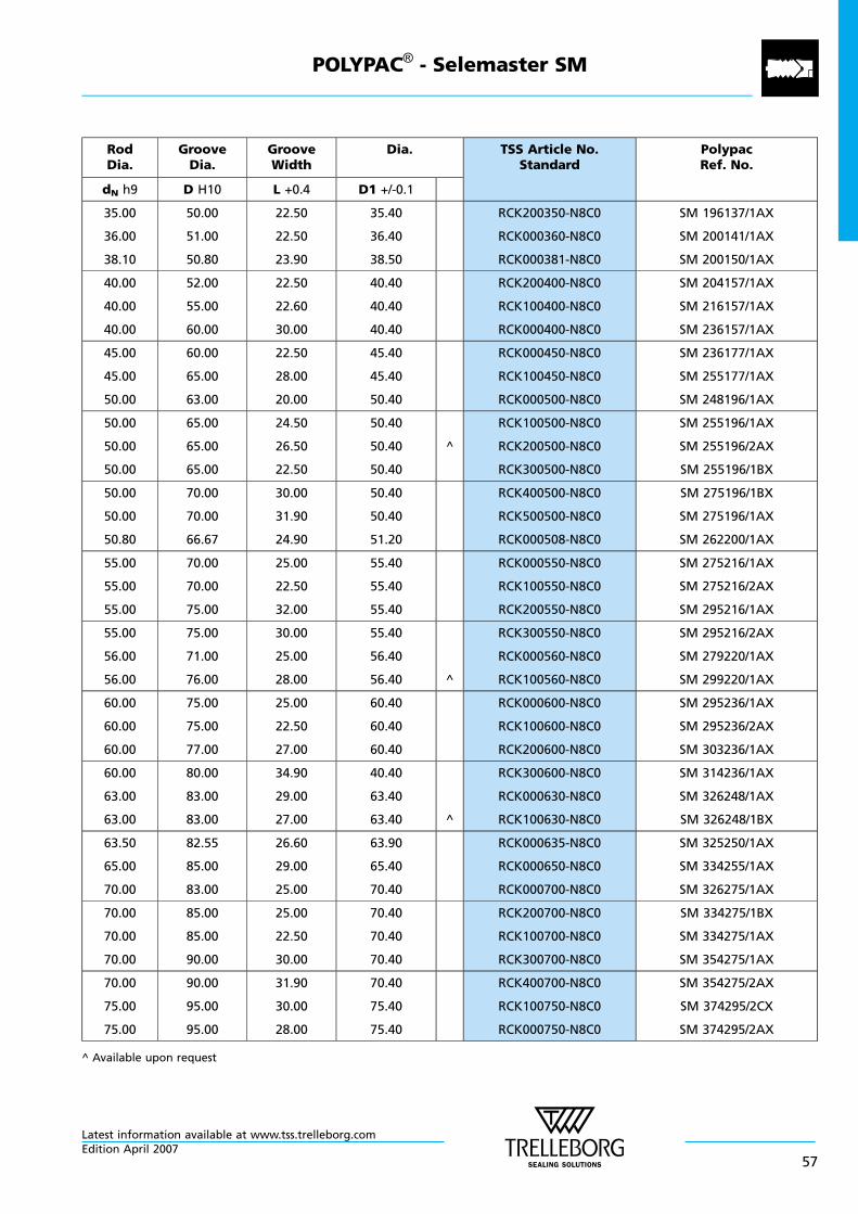
RodDia.
GrooveDia.
GrooveWidth
Dia. TSS Article No.Standard
PolypacRef. No.
dN h9 D H10 L +0.4 D1 +/-0.1
35.00
36.00
38.10
50.00
51.00
50.80
22.50
22.50
23.90
35.40
36.40
38.50
RCK200350-N8C0
RCK000360-N8C0
RCK000381-N8C0
SM 196137/1AX
SM 200141/1AX
SM 200150/1AX
40.00
40.00
40.00
52.00
55.00
60.00
22.50
22.60
30.00
40.40
40.40
40.40
RCK200400-N8C0
RCK100400-N8C0
RCK000400-N8C0
SM 204157/1AX
SM 216157/1AX
SM 236157/1AX
45.00
45.00
50.00
60.00
65.00
63.00
22.50
28.00
20.00
45.40
45.40
50.40
RCK000450-N8C0
RCK100450-N8C0
RCK000500-N8C0
SM 236177/1AX
SM 255177/1AX
SM 248196/1AX
50.00
50.00
50.00
65.00
65.00
65.00
24.50
26.50
22.50
50.40
50.40
50.40
^
RCK100500-N8C0
RCK200500-N8C0
RCK300500-N8C0
SM 255196/1AX
SM 255196/2AX
SM 255196/1BX
50.00
50.00
50.80
70.00
70.00
66.67
30.00
31.90
24.90
50.40
50.40
51.20
RCK400500-N8C0
RCK500500-N8C0
RCK000508-N8C0
SM 275196/1BX
SM 275196/1AX
SM 262200/1AX
55.00
55.00
55.00
70.00
70.00
75.00
25.00
22.50
32.00
55.40
55.40
55.40
RCK000550-N8C0
RCK100550-N8C0
RCK200550-N8C0
SM 275216/1AX
SM 275216/2AX
SM 295216/1AX
55.00
56.00
56.00
75.00
71.00
76.00
30.00
25.00
28.00
55.40
56.40
56.40 ^
RCK300550-N8C0
RCK000560-N8C0
RCK100560-N8C0
SM 295216/2AX
SM 279220/1AX
SM 299220/1AX
60.00
60.00
60.00
75.00
75.00
77.00
25.00
22.50
27.00
60.40
60.40
60.40
RCK000600-N8C0
RCK100600-N8C0
RCK200600-N8C0
SM 295236/1AX
SM 295236/2AX
SM 303236/1AX
60.00
63.00
63.00
80.00
83.00
83.00
34.90
29.00
27.00
40.40
63.40
63.40 ^
RCK300600-N8C0
RCK000630-N8C0
RCK100630-N8C0
SM 314236/1AX
SM 326248/1AX
SM 326248/1BX
63.50
65.00
70.00
82.55
85.00
83.00
26.60
29.00
25.00
63.90
65.40
70.40
RCK000635-N8C0
RCK000650-N8C0
RCK000700-N8C0
SM 325250/1AX
SM 334255/1AX
SM 326275/1AX
70.00
70.00
70.00
85.00
85.00
90.00
25.00
22.50
30.00
70.40
70.40
70.40
RCK200700-N8C0
RCK100700-N8C0
RCK300700-N8C0
SM 334275/1BX
SM 334275/1AX
SM 354275/1AX
70.00
75.00
75.00
90.00
95.00
95.00
31.90
30.00
28.00
70.40
75.40
75.40
RCK400700-N8C0
RCK100750-N8C0
RCK000750-N8C0
SM 354275/2AX
SM 374295/2CX
SM 374295/2AX
^ Available upon request
POLYPAC® - Selemaster SM
Latest information available at www.tss.trelleborg.comEdition April 2007
57
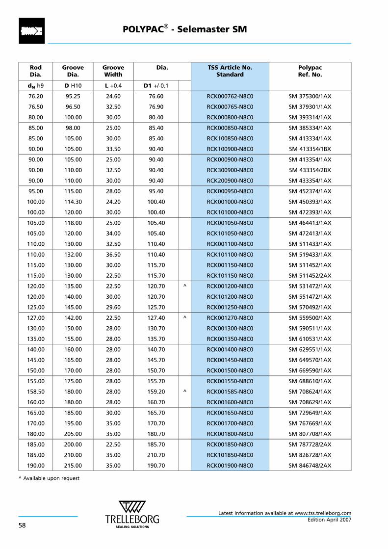
RodDia.
GrooveDia.
GrooveWidth
Dia. TSS Article No.Standard
PolypacRef. No.
dN h9 D H10 L +0.4 D1 +/-0.1
76.20
76.50
80.00
95.25
96.50
100.00
24.60
32.50
30.00
76.60
76.90
80.40
RCK000762-N8C0
RCK000765-N8C0
RCK000800-N8C0
SM 375300/1AX
SM 379301/1AX
SM 393314/1AX
85.00
85.00
90.00
98.00
105.00
105.00
25.00
30.00
33.50
85.40
85.40
90.40
RCK000850-N8C0
RCK100850-N8C0
RCK100900-N8C0
SM 385334/1AX
SM 413334/1AX
SM 413354/1BX
90.00
90.00
90.00
105.00
110.00
110.00
25.00
32.50
30.00
90.40
90.40
90.40
RCK000900-N8C0
RCK300900-N8C0
RCK200900-N8C0
SM 413354/1AX
SM 433354/2BX
SM 433354/1AX
95.00
100.00
100.00
115.00
114.30
120.00
28.00
24.20
30.00
95.40
100.40
100.40
RCK000950-N8C0
RCK001000-N8C0
RCK101000-N8C0
SM 452374/1AX
SM 450393/1AX
SM 472393/1AX
105.00
105.00
110.00
118.00
120.00
130.00
25.00
34.00
32.50
105.40
105.40
110.40
RCK001050-N8C0
RCK101050-N8C0
RCK001100-N8C0
SM 464413/1AX
SM 472413/1AX
SM 511433/1AX
110.00
115.00
115.00
132.00
130.00
130.00
36.50
30.00
22.50
110.40
115.70
115.70
RCK101100-N8C0
RCK001150-N8C0
RCK101150-N8C0
SM 519433/1AX
SM 511452/1AX
SM 511452/2AX
120.00
120.00
125.00
135.00
140.00
145.00
22.50
30.00
29.60
120.70
120.70
125.70
^ RCK001200-N8C0
RCK101200-N8C0
RCK001250-N8C0
SM 531472/1AX
SM 551472/1AX
SM 570492/1AX
127.00
130.00
135.00
142.00
150.00
155.00
22.50
28.00
28.00
127.40
130.70
135.70
^ RCK001270-N8C0
RCK001300-N8C0
RCK001350-N8C0
SM 559500/1AX
SM 590511/1AX
SM 610531/1AX
140.00
145.00
150.00
160.00
165.00
170.00
28.00
28.00
28.00
140.70
145.70
150.70
RCK001400-N8C0
RCK001450-N8C0
RCK001500-N8C0
SM 629551/1AX
SM 649570/1AX
SM 669590/1AX
155.00
158.50
160.00
175.00
180.00
180.00
28.00
28.00
28.00
155.70
159.20
160.70
^
RCK001550-N8C0
RCK001585-N8C0
RCK001600-N8C0
SM 688610/1AX
SM 708624/1AX
SM 708629/1AX
165.00
170.00
180.00
185.00
195.00
205.00
30.00
35.00
35.00
165.70
170.70
180.70
RCK001650-N8C0
RCK001700-N8C0
RCK001800-N8C0
SM 729649/1AX
SM 767669/1AX
SM 807708/1AX
185.00
185.00
190.00
200.00
210.00
215.00
22.50
35.00
35.00
185.70
210.70
190.70
RCK001850-N8C0
RCK101850-N8C0
RCK001900-N8C0
SM 787728/2AX
SM 826728/1AX
SM 846748/2AX
^ Available upon request
POLYPAC® - Selemaster SM
Latest information available at www.tss.trelleborg.com
58Edition April 2007
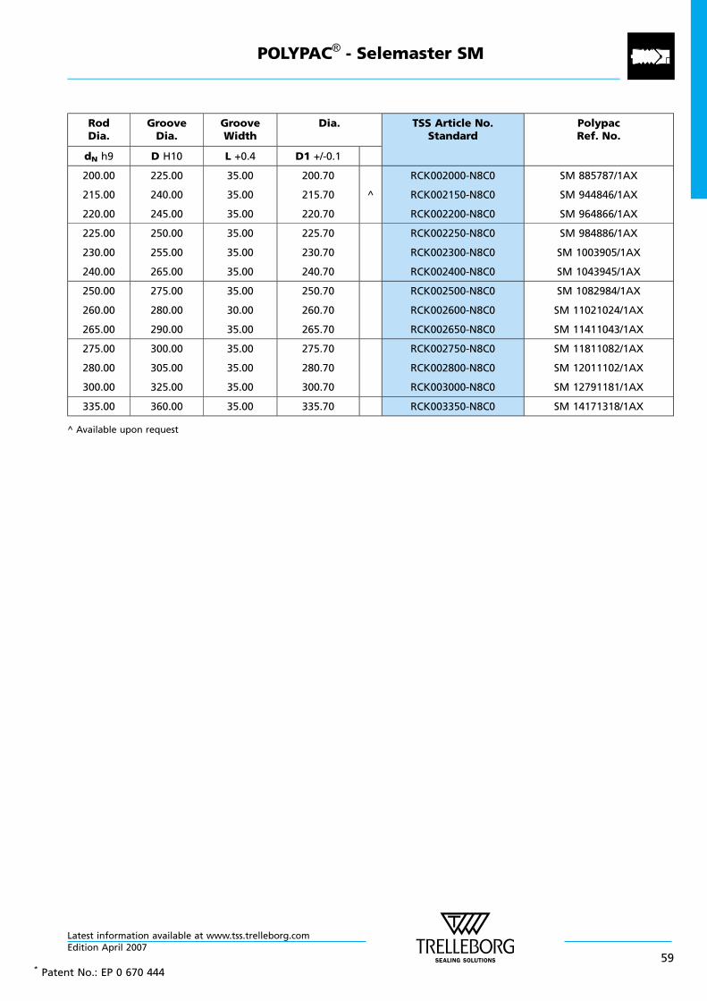
RodDia.
GrooveDia.
GrooveWidth
Dia. TSS Article No.Standard
PolypacRef. No.
dN h9 D H10 L +0.4 D1 +/-0.1
200.00
215.00
220.00
225.00
240.00
245.00
35.00
35.00
35.00
200.70
215.70
220.70
^
RCK002000-N8C0
RCK002150-N8C0
RCK002200-N8C0
SM 885787/1AX
SM 944846/1AX
SM 964866/1AX
225.00
230.00
240.00
250.00
255.00
265.00
35.00
35.00
35.00
225.70
230.70
240.70
RCK002250-N8C0
RCK002300-N8C0
RCK002400-N8C0
SM 984886/1AX
SM 1003905/1AX
SM 1043945/1AX
250.00
260.00
265.00
275.00
280.00
290.00
35.00
30.00
35.00
250.70
260.70
265.70
RCK002500-N8C0
RCK002600-N8C0
RCK002650-N8C0
SM 1082984/1AX
SM 11021024/1AX
SM 11411043/1AX
275.00
280.00
300.00
300.00
305.00
325.00
35.00
35.00
35.00
275.70
280.70
300.70
RCK002750-N8C0
RCK002800-N8C0
RCK003000-N8C0
SM 11811082/1AX
SM 12011102/1AX
SM 12791181/1AX
335.00 360.00 35.00 335.70 RCK003350-N8C0 SM 14171318/1AX
^ Available upon request
* Patent No.: EP 0 670 444
POLYPAC® - Selemaster SM
Latest information available at www.tss.trelleborg.comEdition April 2007
59
POLYPAC® - Selemaster SM
Latest information available at www.tss.trelleborg.com
60Edition April 2007
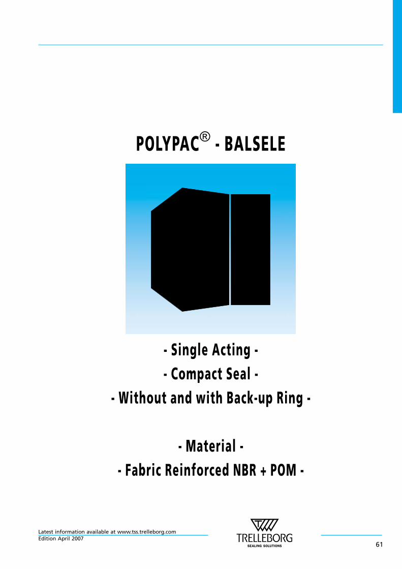
POLYPAC® - BALSELE
- Single Acting -
- Compact Seal -
- Without and with Back-up Ring -
- Material -
- Fabric Reinforced NBR + POM -
Latest information available at www.tss.trelleborg.comEdition April 2007
61

Latest information available at www.tss.trelleborg.com
62Edition April 2007
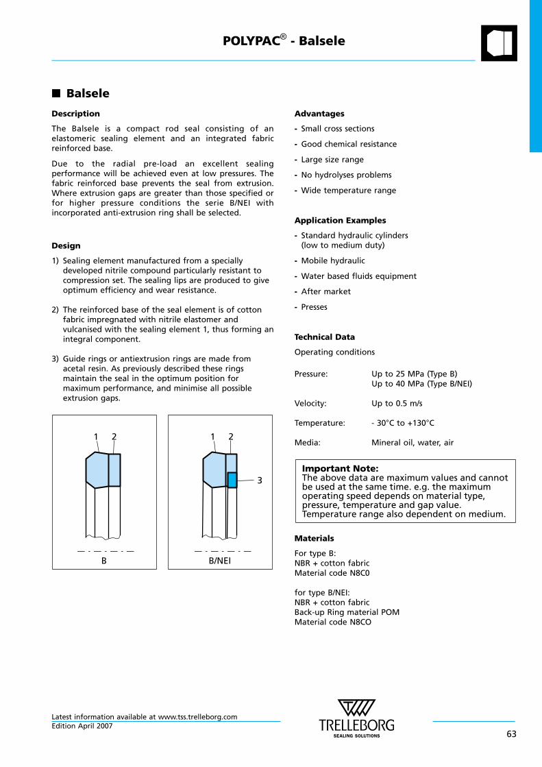
n Balsele
Description
The Balsele is a compact rod seal consisting of anelastomeric sealing element and an integrated fabricreinforced base.
Due to the radial pre-load an excellent sealingperformance will be achieved even at low pressures. Thefabric reinforced base prevents the seal from extrusion.Where extrusion gaps are greater than those specified orfor higher pressure conditions the serie B/NEI withincorporated anti-extrusion ring shall be selected.
Design
1) Sealing element manufactured from a speciallydeveloped nitrile compound particularly resistant tocompression set. The sealing lips are produced to giveoptimum efficiency and wear resistance.
2) The reinforced base of the seal element is of cottonfabric impregnated with nitrile elastomer andvulcanised with the sealing element 1, thus forming anintegral component.
3) Guide rings or antiextrusion rings are made fromacetal resin. As previously described these ringsmaintain the seal in the optimum position formaximum performance, and minimise all possibleextrusion gaps.
1 2 1 2
3
B B/NEI
Advantages
- Small cross sections
- Good chemical resistance
- Large size range
- No hydrolyses problems
- Wide temperature range
Application Examples
- Standard hydraulic cylinders(low to medium duty)
- Mobile hydraulic
- Water based fluids equipment
- After market
- Presses
Technical Data
Operating conditions
Pressure: Up to 25 MPa (Type B)Up to 40 MPa (Type B/NEI)
Velocity: Up to 0.5 m/s
Temperature: - 30°C to +130°C
Media: Mineral oil, water, air
Important Note:The above data are maximum values and cannotbe used at the same time. e.g. the maximumoperating speed depends on material type,pressure, temperature and gap value.Temperature range also dependent on medium.
Materials
For type B:NBR + cotton fabricMaterial code N8C0
for type B/NEI:NBR + cotton fabricBack-up Ring material POMMaterial code N8CO
POLYPAC® - Balsele
Latest information available at www.tss.trelleborg.comEdition April 2007
63
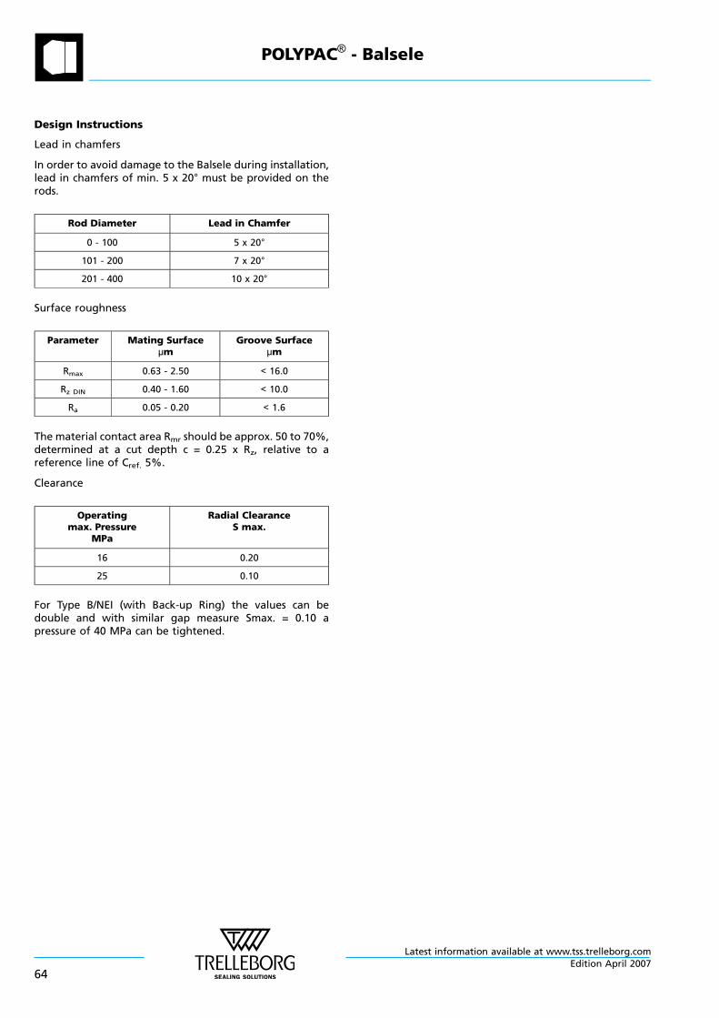
Design Instructions
Lead in chamfers
In order to avoid damage to the Balsele during installation,lead in chamfers of min. 5 x 20° must be provided on therods.
Rod Diameter Lead in Chamfer
0 - 100 5 x 20°
101 - 200 7 x 20°
201 - 400 10 x 20°
Surface roughness
Parameter Mating Surfaceµm
Groove Surfaceµm
Rmax 0.63 - 2.50 < 16.0
Rz DIN 0.40 - 1.60 < 10.0
Ra 0.05 - 0.20 < 1.6
The material contact area Rmr should be approx. 50 to 70%,determined at a cut depth c = 0.25 x Rz, relative to areference line of Cref. 5%.
Clearance
Operatingmax. Pressure
MPa
Radial ClearanceS max.
16 0.20
25 0.10
For Type B/NEI (with Back-up Ring) the values can bedouble and with similar gap measure Smax. = 0.10 apressure of 40 MPa can be tightened.
POLYPAC® - Balsele
Latest information available at www.tss.trelleborg.com
64Edition April 2007
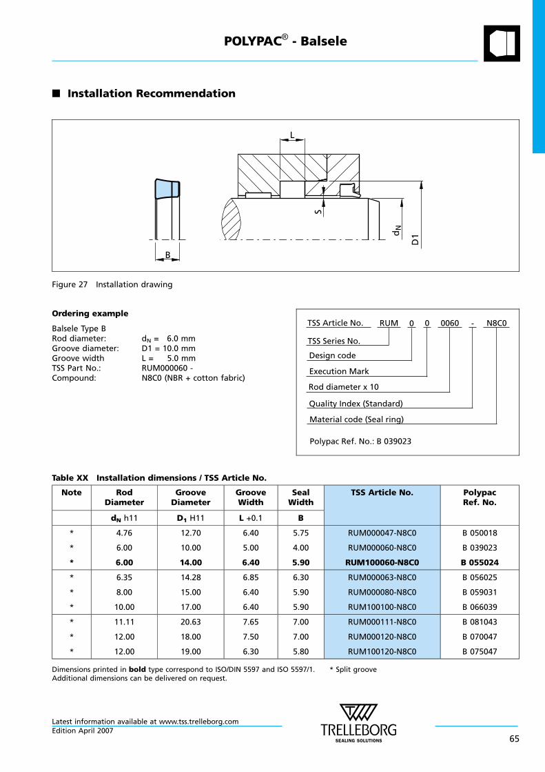
n Installation Recommendation
B
L
S
D1d
N
Figure 27 Installation drawing
Ordering example
Balsele Type BRod diameter: dN = 6.0 mmGroove diameter: D1 = 10.0 mmGroove width L = 5.0 mmTSS Part No.: RUM000060 -Compound: N8C0 (NBR + cotton fabric)
Material code (Seal ring)
TSS Series No.
TSS Article No. N8C00
Rod diameter x 10
RUM
Quality Index (Standard)
0060
Design code
0
Execution Mark
-
Polypac Ref. No.: B 039023
Table XX Installation dimensions / TSS Article No.
Note RodDiameter
GrooveDiameter
GrooveWidth
SealWidth
TSS Article No. PolypacRef. No.
dN h11 D1 H11 L +0.1 B
*
*
*
4.76
6.00
6.00
12.70
10.00
14.00
6.40
5.00
6.40
5.75
4.00
5.90
RUM000047-N8C0
RUM000060-N8C0
RUM100060-N8C0
B 050018
B 039023
B 055024
*
*
*
6.35
8.00
10.00
14.28
15.00
17.00
6.85
6.40
6.40
6.30
5.90
5.90
RUM000063-N8C0
RUM000080-N8C0
RUM100100-N8C0
B 056025
B 059031
B 066039
*
*
*
11.11
12.00
12.00
20.63
18.00
19.00
7.65
7.50
6.30
7.00
7.00
5.80
RUM000111-N8C0
RUM000120-N8C0
RUM100120-N8C0
B 081043
B 070047
B 075047
Dimensions printed in bold type correspond to ISO/DIN 5597 and ISO 5597/1. * Split grooveAdditional dimensions can be delivered on request.
POLYPAC® - Balsele
Latest information available at www.tss.trelleborg.comEdition April 2007
65
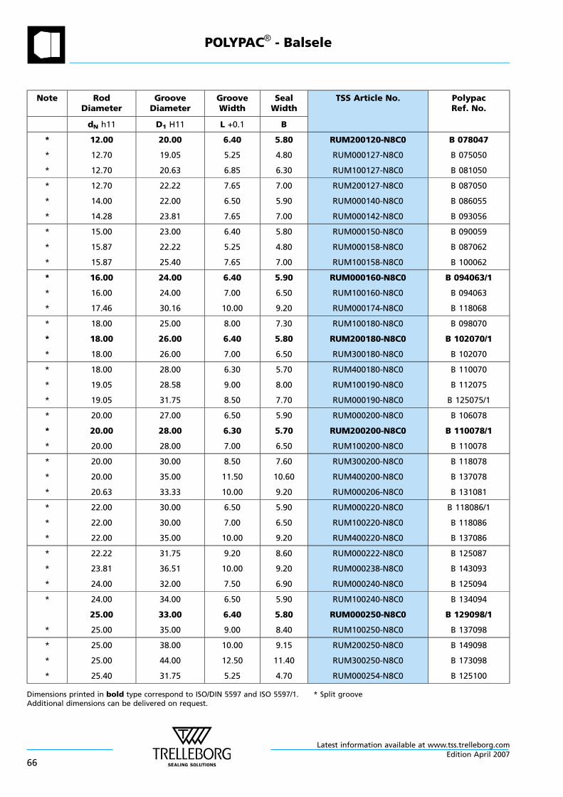
Note RodDiameter
GrooveDiameter
GrooveWidth
SealWidth
TSS Article No. PolypacRef. No.
dN h11 D1 H11 L +0.1 B
*
*
*
12.00
12.70
12.70
20.00
19.05
20.63
6.40
5.25
6.85
5.80
4.80
6.30
RUM200120-N8C0
RUM000127-N8C0
RUM100127-N8C0
B 078047
B 075050
B 081050
*
*
*
12.70
14.00
14.28
22.22
22.00
23.81
7.65
6.50
7.65
7.00
5.90
7.00
RUM200127-N8C0
RUM000140-N8C0
RUM000142-N8C0
B 087050
B 086055
B 093056
*
*
*
15.00
15.87
15.87
23.00
22.22
25.40
6.40
5.25
7.65
5.80
4.80
7.00
RUM000150-N8C0
RUM000158-N8C0
RUM100158-N8C0
B 090059
B 087062
B 100062
*
*
*
16.00
16.00
17.46
24.00
24.00
30.16
6.40
7.00
10.00
5.90
6.50
9.20
RUM000160-N8C0
RUM100160-N8C0
RUM000174-N8C0
B 094063/1
B 094063
B 118068
*
*
*
18.00
18.00
18.00
25.00
26.00
26.00
8.00
6.40
7.00
7.30
5.80
6.50
RUM100180-N8C0
RUM200180-N8C0
RUM300180-N8C0
B 098070
B 102070/1
B 102070
*
*
*
18.00
19.05
19.05
28.00
28.58
31.75
6.30
9.00
8.50
5.70
8.00
7.70
RUM400180-N8C0
RUM100190-N8C0
RUM000190-N8C0
B 110070
B 112075
B 125075/1
*
*
*
20.00
20.00
20.00
27.00
28.00
28.00
6.50
6.30
7.00
5.90
5.70
6.50
RUM000200-N8C0
RUM200200-N8C0
RUM100200-N8C0
B 106078
B 110078/1
B 110078
*
*
*
20.00
20.00
20.63
30.00
35.00
33.33
8.50
11.50
10.00
7.60
10.60
9.20
RUM300200-N8C0
RUM400200-N8C0
RUM000206-N8C0
B 118078
B 137078
B 131081
*
*
*
22.00
22.00
22.00
30.00
30.00
35.00
6.50
7.00
10.00
5.90
6.50
9.20
RUM000220-N8C0
RUM100220-N8C0
RUM400220-N8C0
B 118086/1
B 118086
B 137086
*
*
*
22.22
23.81
24.00
31.75
36.51
32.00
9.20
10.00
7.50
8.60
9.20
6.90
RUM000222-N8C0
RUM000238-N8C0
RUM000240-N8C0
B 125087
B 143093
B 125094
*
*
24.00
25.00
25.00
34.00
33.00
35.00
6.50
6.40
9.00
5.90
5.80
8.40
RUM100240-N8C0
RUM000250-N8C0
RUM100250-N8C0
B 134094
B 129098/1
B 137098
*
*
*
25.00
25.00
25.40
38.00
44.00
31.75
10.00
12.50
5.25
9.15
11.40
4.70
RUM200250-N8C0
RUM300250-N8C0
RUM000254-N8C0
B 149098
B 173098
B 125100
Dimensions printed in bold type correspond to ISO/DIN 5597 and ISO 5597/1. * Split grooveAdditional dimensions can be delivered on request.
POLYPAC® - Balsele
Latest information available at www.tss.trelleborg.com
66Edition April 2007
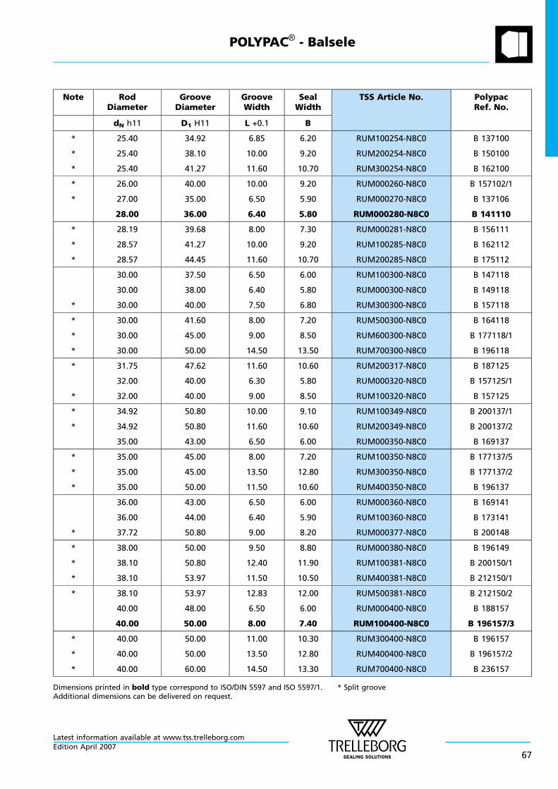
Note RodDiameter
GrooveDiameter
GrooveWidth
SealWidth
TSS Article No. PolypacRef. No.
dN h11 D1 H11 L +0.1 B
*
*
*
25.40
25.40
25.40
34.92
38.10
41.27
6.85
10.00
11.60
6.20
9.20
10.70
RUM100254-N8C0
RUM200254-N8C0
RUM300254-N8C0
B 137100
B 150100
B 162100
*
*
26.00
27.00
28.00
40.00
35.00
36.00
10.00
6.50
6.40
9.20
5.90
5.80
RUM000260-N8C0
RUM000270-N8C0
RUM000280-N8C0
B 157102/1
B 137106
B 141110
*
*
*
28.19
28.57
28.57
39.68
41.27
44.45
8.00
10.00
11.60
7.30
9.20
10.70
RUM000281-N8C0
RUM100285-N8C0
RUM200285-N8C0
B 156111
B 162112
B 175112
*
30.00
30.00
30.00
37.50
38.00
40.00
6.50
6.40
7.50
6.00
5.80
6.80
RUM100300-N8C0
RUM000300-N8C0
RUM300300-N8C0
B 147118
B 149118
B 157118
*
*
*
30.00
30.00
30.00
41.60
45.00
50.00
8.00
9.00
14.50
7.20
8.50
13.50
RUM500300-N8C0
RUM600300-N8C0
RUM700300-N8C0
B 164118
B 177118/1
B 196118
*
*
31.75
32.00
32.00
47.62
40.00
40.00
11.60
6.30
9.00
10.60
5.80
8.50
RUM200317-N8C0
RUM000320-N8C0
RUM100320-N8C0
B 187125
B 157125/1
B 157125
*
*
34.92
34.92
35.00
50.80
50.80
43.00
10.00
11.60
6.50
9.10
10.60
6.00
RUM100349-N8C0
RUM200349-N8C0
RUM000350-N8C0
B 200137/1
B 200137/2
B 169137
*
*
*
35.00
35.00
35.00
45.00
45.00
50.00
8.00
13.50
11.50
7.20
12.80
10.60
RUM100350-N8C0
RUM300350-N8C0
RUM400350-N8C0
B 177137/5
B 177137/2
B 196137
*
36.00
36.00
37.72
43.00
44.00
50.80
6.50
6.40
9.00
6.00
5.90
8.20
RUM000360-N8C0
RUM100360-N8C0
RUM000377-N8C0
B 169141
B 173141
B 200148
*
*
*
38.00
38.10
38.10
50.00
50.80
53.97
9.50
12.40
11.50
8.80
11.90
10.50
RUM000380-N8C0
RUM100381-N8C0
RUM400381-N8C0
B 196149
B 200150/1
B 212150/1
* 38.10
40.00
40.00
53.97
48.00
50.00
12.83
6.50
8.00
12.00
6.00
7.40
RUM500381-N8C0
RUM000400-N8C0
RUM100400-N8C0
B 212150/2
B 188157
B 196157/3
*
*
*
40.00
40.00
40.00
50.00
50.00
60.00
11.00
13.50
14.50
10.30
12.80
13.30
RUM300400-N8C0
RUM400400-N8C0
RUM700400-N8C0
B 196157
B 196157/2
B 236157
Dimensions printed in bold type correspond to ISO/DIN 5597 and ISO 5597/1. * Split grooveAdditional dimensions can be delivered on request.
POLYPAC® - Balsele
Latest information available at www.tss.trelleborg.comEdition April 2007
67
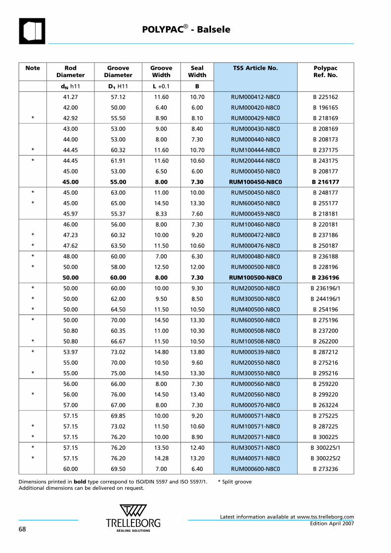
Note RodDiameter
GrooveDiameter
GrooveWidth
SealWidth
TSS Article No. PolypacRef. No.
dN h11 D1 H11 L +0.1 B
*
41.27
42.00
42.92
57.12
50.00
55.50
11.60
6.40
8.90
10.70
6.00
8.10
RUM000412-N8C0
RUM000420-N8C0
RUM000429-N8C0
B 225162
B 196165
B 218169
*
43.00
44.00
44.45
53.00
53.00
60.32
9.00
8.00
11.60
8.40
7.30
10.70
RUM000430-N8C0
RUM000440-N8C0
RUM100444-N8C0
B 208169
B 208173
B 237175
* 44.45
45.00
45.00
61.91
53.00
55.00
11.60
6.50
8.00
10.60
6.00
7.30
RUM200444-N8C0
RUM000450-N8C0
RUM100450-N8C0
B 243175
B 208177
B 216177
*
*
45.00
45.00
45.97
63.00
65.00
55.37
11.00
14.50
8.33
10.00
13.30
7.60
RUM500450-N8C0
RUM600450-N8C0
RUM000459-N8C0
B 248177
B 255177
B 218181
*
*
46.00
47.23
47.62
56.00
60.32
63.50
8.00
10.00
11.50
7.30
9.20
10.60
RUM100460-N8C0
RUM000472-N8C0
RUM000476-N8C0
B 220181
B 237186
B 250187
*
*
48.00
50.00
50.00
60.00
58.00
60.00
7.00
12.50
8.00
6.30
12.00
7.30
RUM000480-N8C0
RUM000500-N8C0
RUM100500-N8C0
B 236188
B 228196
B 236196
*
*
*
50.00
50.00
50.00
60.00
62.00
64.50
10.00
9.50
11.50
9.30
8.50
10.50
RUM200500-N8C0
RUM300500-N8C0
RUM400500-N8C0
B 236196/1
B 244196/1
B 254196
*
*
50.00
50.80
50.80
70.00
60.35
66.67
14.50
11.00
11.50
13.30
10.30
10.50
RUM600500-N8C0
RUM000508-N8C0
RUM100508-N8C0
B 275196
B 237200
B 262200
*
*
53.97
55.00
55.00
73.02
70.00
75.00
14.80
10.50
14.50
13.80
9.60
13.30
RUM000539-N8C0
RUM200550-N8C0
RUM300550-N8C0
B 287212
B 275216
B 295216
*
56.00
56.00
57.00
66.00
76.00
67.00
8.00
14.50
8.00
7.30
13.40
7.30
RUM000560-N8C0
RUM200560-N8C0
RUM000570-N8C0
B 259220
B 299220
B 263224
*
*
57.15
57.15
57.15
69.85
73.02
76.20
10.00
11.50
10.00
9.20
10.60
8.90
RUM000571-N8C0
RUM100571-N8C0
RUM200571-N8C0
B 275225
B 287225
B 300225
*
*
57.15
57.15
60.00
76.20
76.20
69.50
13.50
14.28
7.00
12.40
13.20
6.40
RUM300571-N8C0
RUM400571-N8C0
RUM000600-N8C0
B 300225/1
B 300225/2
B 273236
Dimensions printed in bold type correspond to ISO/DIN 5597 and ISO 5597/1. * Split grooveAdditional dimensions can be delivered on request.
POLYPAC® - Balsele
Latest information available at www.tss.trelleborg.com
68Edition April 2007
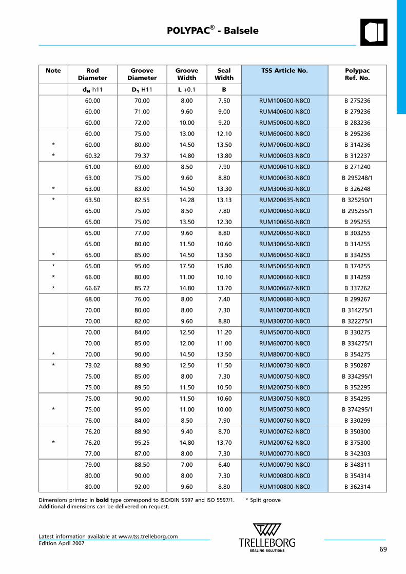
Note RodDiameter
GrooveDiameter
GrooveWidth
SealWidth
TSS Article No. PolypacRef. No.
dN h11 D1 H11 L +0.1 B
60.00
60.00
60.00
70.00
71.00
72.00
8.00
9.60
10.00
7.50
9.00
9.20
RUM100600-N8C0
RUM400600-N8C0
RUM500600-N8C0
B 275236
B 279236
B 283236
*
*
60.00
60.00
60.32
75.00
80.00
79.37
13.00
14.50
14.80
12.10
13.50
13.80
RUM600600-N8C0
RUM700600-N8C0
RUM000603-N8C0
B 295236
B 314236
B 312237
*
61.00
63.00
63.00
69.00
75.00
83.00
8.50
9.60
14.50
7.90
8.80
13.30
RUM000610-N8C0
RUM000630-N8C0
RUM300630-N8C0
B 271240
B 295248/1
B 326248
* 63.50
65.00
65.00
82.55
75.00
75.00
14.28
8.50
13.50
13.13
7.80
12.30
RUM200635-N8C0
RUM000650-N8C0
RUM100650-N8C0
B 325250/1
B 295255/1
B 295255
*
65.00
65.00
65.00
77.00
80.00
85.00
9.60
11.50
14.50
8.80
10.60
13.50
RUM200650-N8C0
RUM300650-N8C0
RUM600650-N8C0
B 303255
B 314255
B 334255
*
*
*
65.00
66.00
66.67
95.00
80.00
85.72
17.50
11.00
14.80
15.80
10.10
13.70
RUM500650-N8C0
RUM000660-N8C0
RUM000667-N8C0
B 374255
B 314259
B 337262
68.00
70.00
70.00
76.00
80.00
82.00
8.00
8.00
9.60
7.40
7.30
8.80
RUM000680-N8C0
RUM100700-N8C0
RUM300700-N8C0
B 299267
B 314275/1
B 322275/1
*
70.00
70.00
70.00
84.00
85.00
90.00
12.50
12.00
14.50
11.20
11.00
13.50
RUM500700-N8C0
RUM600700-N8C0
RUM800700-N8C0
B 330275
B 334275/1
B 354275
* 73.02
75.00
75.00
88.90
85.00
89.50
12.50
8.00
11.50
11.50
7.30
10.50
RUM000730-N8C0
RUM000750-N8C0
RUM200750-N8C0
B 350287
B 334295/1
B 352295
*
75.00
75.00
76.00
90.00
95.00
84.00
11.50
11.00
8.50
10.60
10.00
7.90
RUM300750-N8C0
RUM500750-N8C0
RUM000760-N8C0
B 354295
B 374295/1
B 330299
*
76.20
76.20
77.00
88.90
95.25
87.00
9.40
14.80
8.00
8.70
13.70
7.30
RUM000762-N8C0
RUM200762-N8C0
RUM000770-N8C0
B 350300
B 375300
B 342303
79.00
80.00
80.00
88.50
90.00
92.00
7.00
8.00
9.60
6.40
7.30
8.80
RUM000790-N8C0
RUM000800-N8C0
RUM100800-N8C0
B 348311
B 354314
B 362314
Dimensions printed in bold type correspond to ISO/DIN 5597 and ISO 5597/1. * Split grooveAdditional dimensions can be delivered on request.
POLYPAC® - Balsele
Latest information available at www.tss.trelleborg.comEdition April 2007
69
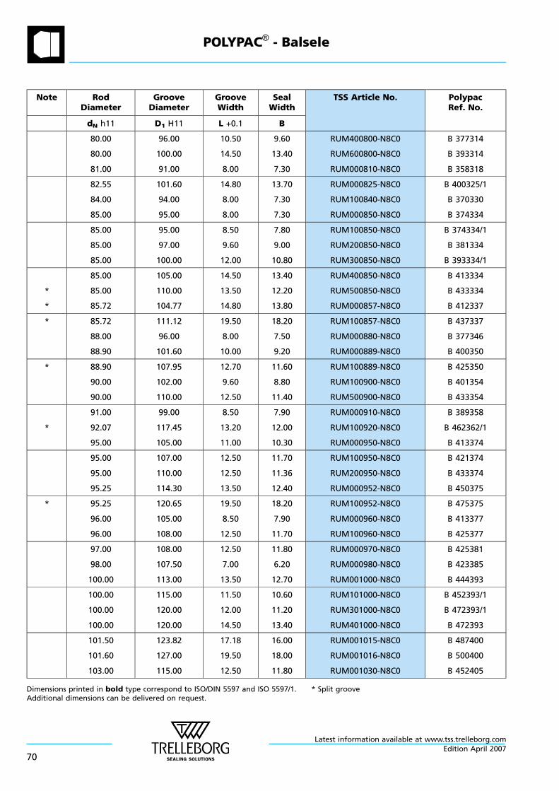
Note RodDiameter
GrooveDiameter
GrooveWidth
SealWidth
TSS Article No. PolypacRef. No.
dN h11 D1 H11 L +0.1 B
80.00
80.00
81.00
96.00
100.00
91.00
10.50
14.50
8.00
9.60
13.40
7.30
RUM400800-N8C0
RUM600800-N8C0
RUM000810-N8C0
B 377314
B 393314
B 358318
82.55
84.00
85.00
101.60
94.00
95.00
14.80
8.00
8.00
13.70
7.30
7.30
RUM000825-N8C0
RUM100840-N8C0
RUM000850-N8C0
B 400325/1
B 370330
B 374334
85.00
85.00
85.00
95.00
97.00
100.00
8.50
9.60
12.00
7.80
9.00
10.80
RUM100850-N8C0
RUM200850-N8C0
RUM300850-N8C0
B 374334/1
B 381334
B 393334/1
*
*
85.00
85.00
85.72
105.00
110.00
104.77
14.50
13.50
14.80
13.40
12.20
13.80
RUM400850-N8C0
RUM500850-N8C0
RUM000857-N8C0
B 413334
B 433334
B 412337
* 85.72
88.00
88.90
111.12
96.00
101.60
19.50
8.00
10.00
18.20
7.50
9.20
RUM100857-N8C0
RUM000880-N8C0
RUM000889-N8C0
B 437337
B 377346
B 400350
* 88.90
90.00
90.00
107.95
102.00
110.00
12.70
9.60
12.50
11.60
8.80
11.40
RUM100889-N8C0
RUM100900-N8C0
RUM500900-N8C0
B 425350
B 401354
B 433354
*
91.00
92.07
95.00
99.00
117.45
105.00
8.50
13.20
11.00
7.90
12.00
10.30
RUM000910-N8C0
RUM100920-N8C0
RUM000950-N8C0
B 389358
B 462362/1
B 413374
95.00
95.00
95.25
107.00
110.00
114.30
12.50
12.50
13.50
11.70
11.36
12.40
RUM100950-N8C0
RUM200950-N8C0
RUM000952-N8C0
B 421374
B 433374
B 450375
* 95.25
96.00
96.00
120.65
105.00
108.00
19.50
8.50
12.50
18.20
7.90
11.70
RUM100952-N8C0
RUM000960-N8C0
RUM100960-N8C0
B 475375
B 413377
B 425377
97.00
98.00
100.00
108.00
107.50
113.00
12.50
7.00
13.50
11.80
6.20
12.70
RUM000970-N8C0
RUM000980-N8C0
RUM001000-N8C0
B 425381
B 423385
B 444393
100.00
100.00
100.00
115.00
120.00
120.00
11.50
12.00
14.50
10.60
11.20
13.40
RUM101000-N8C0
RUM301000-N8C0
RUM401000-N8C0
B 452393/1
B 472393/1
B 472393
101.50
101.60
103.00
123.82
127.00
115.00
17.18
19.50
12.50
16.00
18.00
11.80
RUM001015-N8C0
RUM001016-N8C0
RUM001030-N8C0
B 487400
B 500400
B 452405
Dimensions printed in bold type correspond to ISO/DIN 5597 and ISO 5597/1. * Split grooveAdditional dimensions can be delivered on request.
POLYPAC® - Balsele
Latest information available at www.tss.trelleborg.com
70Edition April 2007
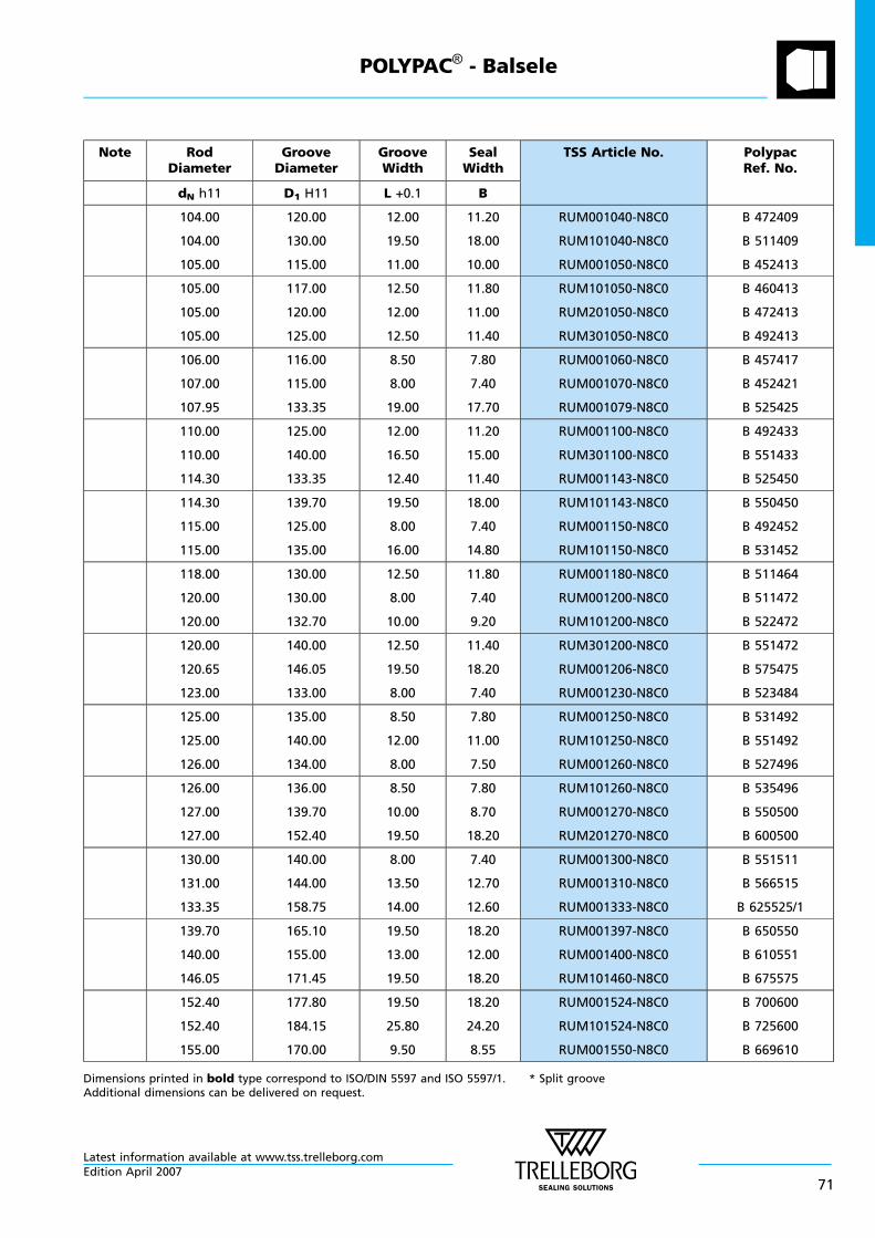
Note RodDiameter
GrooveDiameter
GrooveWidth
SealWidth
TSS Article No. PolypacRef. No.
dN h11 D1 H11 L +0.1 B
104.00
104.00
105.00
120.00
130.00
115.00
12.00
19.50
11.00
11.20
18.00
10.00
RUM001040-N8C0
RUM101040-N8C0
RUM001050-N8C0
B 472409
B 511409
B 452413
105.00
105.00
105.00
117.00
120.00
125.00
12.50
12.00
12.50
11.80
11.00
11.40
RUM101050-N8C0
RUM201050-N8C0
RUM301050-N8C0
B 460413
B 472413
B 492413
106.00
107.00
107.95
116.00
115.00
133.35
8.50
8.00
19.00
7.80
7.40
17.70
RUM001060-N8C0
RUM001070-N8C0
RUM001079-N8C0
B 457417
B 452421
B 525425
110.00
110.00
114.30
125.00
140.00
133.35
12.00
16.50
12.40
11.20
15.00
11.40
RUM001100-N8C0
RUM301100-N8C0
RUM001143-N8C0
B 492433
B 551433
B 525450
114.30
115.00
115.00
139.70
125.00
135.00
19.50
8.00
16.00
18.00
7.40
14.80
RUM101143-N8C0
RUM001150-N8C0
RUM101150-N8C0
B 550450
B 492452
B 531452
118.00
120.00
120.00
130.00
130.00
132.70
12.50
8.00
10.00
11.80
7.40
9.20
RUM001180-N8C0
RUM001200-N8C0
RUM101200-N8C0
B 511464
B 511472
B 522472
120.00
120.65
123.00
140.00
146.05
133.00
12.50
19.50
8.00
11.40
18.20
7.40
RUM301200-N8C0
RUM001206-N8C0
RUM001230-N8C0
B 551472
B 575475
B 523484
125.00
125.00
126.00
135.00
140.00
134.00
8.50
12.00
8.00
7.80
11.00
7.50
RUM001250-N8C0
RUM101250-N8C0
RUM001260-N8C0
B 531492
B 551492
B 527496
126.00
127.00
127.00
136.00
139.70
152.40
8.50
10.00
19.50
7.80
8.70
18.20
RUM101260-N8C0
RUM001270-N8C0
RUM201270-N8C0
B 535496
B 550500
B 600500
130.00
131.00
133.35
140.00
144.00
158.75
8.00
13.50
14.00
7.40
12.70
12.60
RUM001300-N8C0
RUM001310-N8C0
RUM001333-N8C0
B 551511
B 566515
B 625525/1
139.70
140.00
146.05
165.10
155.00
171.45
19.50
13.00
19.50
18.20
12.00
18.20
RUM001397-N8C0
RUM001400-N8C0
RUM101460-N8C0
B 650550
B 610551
B 675575
152.40
152.40
155.00
177.80
184.15
170.00
19.50
25.80
9.50
18.20
24.20
8.55
RUM001524-N8C0
RUM101524-N8C0
RUM001550-N8C0
B 700600
B 725600
B 669610
Dimensions printed in bold type correspond to ISO/DIN 5597 and ISO 5597/1. * Split grooveAdditional dimensions can be delivered on request.
POLYPAC® - Balsele
Latest information available at www.tss.trelleborg.comEdition April 2007
71
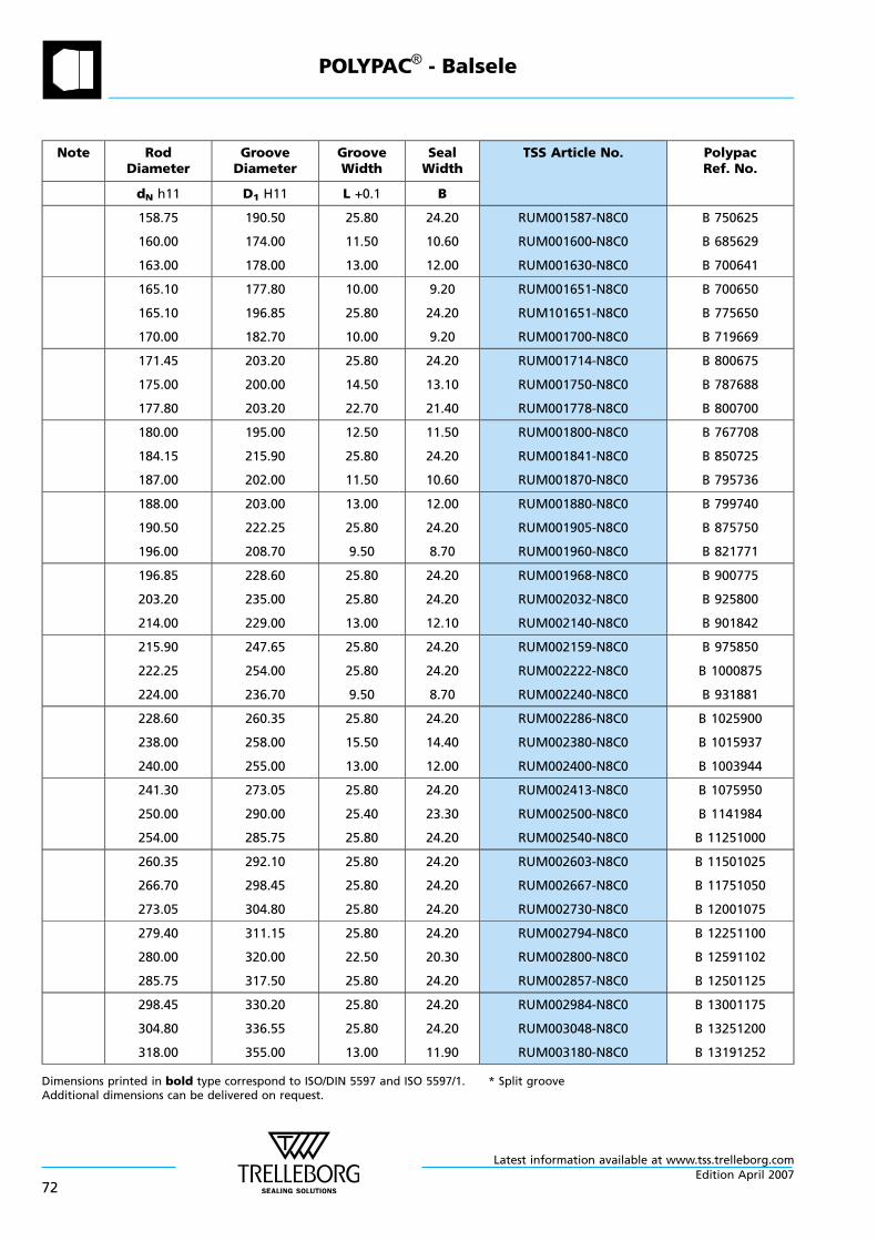
Note RodDiameter
GrooveDiameter
GrooveWidth
SealWidth
TSS Article No. PolypacRef. No.
dN h11 D1 H11 L +0.1 B
158.75
160.00
163.00
190.50
174.00
178.00
25.80
11.50
13.00
24.20
10.60
12.00
RUM001587-N8C0
RUM001600-N8C0
RUM001630-N8C0
B 750625
B 685629
B 700641
165.10
165.10
170.00
177.80
196.85
182.70
10.00
25.80
10.00
9.20
24.20
9.20
RUM001651-N8C0
RUM101651-N8C0
RUM001700-N8C0
B 700650
B 775650
B 719669
171.45
175.00
177.80
203.20
200.00
203.20
25.80
14.50
22.70
24.20
13.10
21.40
RUM001714-N8C0
RUM001750-N8C0
RUM001778-N8C0
B 800675
B 787688
B 800700
180.00
184.15
187.00
195.00
215.90
202.00
12.50
25.80
11.50
11.50
24.20
10.60
RUM001800-N8C0
RUM001841-N8C0
RUM001870-N8C0
B 767708
B 850725
B 795736
188.00
190.50
196.00
203.00
222.25
208.70
13.00
25.80
9.50
12.00
24.20
8.70
RUM001880-N8C0
RUM001905-N8C0
RUM001960-N8C0
B 799740
B 875750
B 821771
196.85
203.20
214.00
228.60
235.00
229.00
25.80
25.80
13.00
24.20
24.20
12.10
RUM001968-N8C0
RUM002032-N8C0
RUM002140-N8C0
B 900775
B 925800
B 901842
215.90
222.25
224.00
247.65
254.00
236.70
25.80
25.80
9.50
24.20
24.20
8.70
RUM002159-N8C0
RUM002222-N8C0
RUM002240-N8C0
B 975850
B 1000875
B 931881
228.60
238.00
240.00
260.35
258.00
255.00
25.80
15.50
13.00
24.20
14.40
12.00
RUM002286-N8C0
RUM002380-N8C0
RUM002400-N8C0
B 1025900
B 1015937
B 1003944
241.30
250.00
254.00
273.05
290.00
285.75
25.80
25.40
25.80
24.20
23.30
24.20
RUM002413-N8C0
RUM002500-N8C0
RUM002540-N8C0
B 1075950
B 1141984
B 11251000
260.35
266.70
273.05
292.10
298.45
304.80
25.80
25.80
25.80
24.20
24.20
24.20
RUM002603-N8C0
RUM002667-N8C0
RUM002730-N8C0
B 11501025
B 11751050
B 12001075
279.40
280.00
285.75
311.15
320.00
317.50
25.80
22.50
25.80
24.20
20.30
24.20
RUM002794-N8C0
RUM002800-N8C0
RUM002857-N8C0
B 12251100
B 12591102
B 12501125
298.45
304.80
318.00
330.20
336.55
355.00
25.80
25.80
13.00
24.20
24.20
11.90
RUM002984-N8C0
RUM003048-N8C0
RUM003180-N8C0
B 13001175
B 13251200
B 13191252
Dimensions printed in bold type correspond to ISO/DIN 5597 and ISO 5597/1. * Split grooveAdditional dimensions can be delivered on request.
POLYPAC® - Balsele
Latest information available at www.tss.trelleborg.com
72Edition April 2007
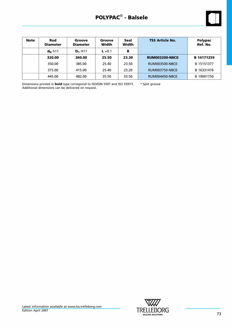
Note RodDiameter
GrooveDiameter
GrooveWidth
SealWidth
TSS Article No. PolypacRef. No.
dN h11 D1 H11 L +0.1 B
320.00
350.00
375.00
360.00
385.00
415.00
25.50
25.40
25.40
23.30
23.50
23.20
RUM003200-N8C0
RUM003500-N8C0
RUM003750-N8C0
B 14171259
B 15151377
B 16331476
445.00 482.00 35.50 33.50 RUM004450-N8C0 B 19001750
Dimensions printed in bold type correspond to ISO/DIN 5597 and ISO 5597/1. * Split grooveAdditional dimensions can be delivered on request.
POLYPAC® - Balsele
Latest information available at www.tss.trelleborg.comEdition April 2007
73
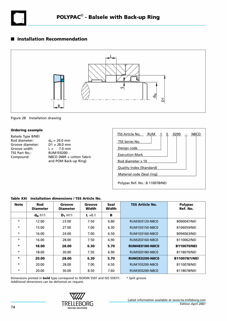
n Installation Recommendation
B
L
S
D1d
N
Figure 28 Installation drawing
Ordering example
Balsele Type B/NEIRod diameter: dN = 20.0 mmGroove diameter: D1 = 28.0 mmGroove width L = 7.0 mmTSS Part No.: RUM1E0200 -Compound: N8CO (NBR + cotton fabric
and POM Back-up Ring)
Material code (Seal ring)
TSS Series No.
TSS Article No. N8COE
Rod diameter x 10
RUM
Quality Index (Standard)
0200
Design code
1
Execution Mark
-
Polypac Ref. No.: B 110078/NEI
Table XXI Installation dimensions / TSS Article No.
Note RodDiameter
GrooveDiameter
GrooveWidth
SealWidth
TSS Article No. PolypacRef. No.
dN h11 D1 H11 L +0.1 B
*
*
*
12.00
15.00
16.00
23.00
27.00
24.00
7.50
7.00
7.00
6.80
6.30
6.50
RUM3E0120-N8C0
RUM1E0150-N8C0
RUM1E0160-N8C0
B090047/NEI
B106059/NEI
B094063/NEI
*
*
*
16.00
18.00
18.00
28.00
28.00
30.00
7.50
6.30
7.50
6.90
5.70
6.90
RUM2E0160-N8C0
RUM4E0180-N8C0
RUM5E0180-N8C0
B110062/NEI
B110070/NEI
B118070/NEI
*
*
*
20.00
20.00
20.00
28.00
28.00
30.00
6.30
7.00
8.50
5.70
6.50
7.60
RUM2E0200-N8C0
RUM1E0200-N8C0
RUM3E0200-N8C0
B110078/1/NEI
B110078/NEI
B118078/NEI
Dimensions printed in bold type correspond to ISO/DIN 5597 and ISO 5597/1. * Split grooveAdditional dimensions can be delivered on request.
POLYPAC® - Balsele with Back-up Ring
Latest information available at www.tss.trelleborg.com
74Edition April 2007
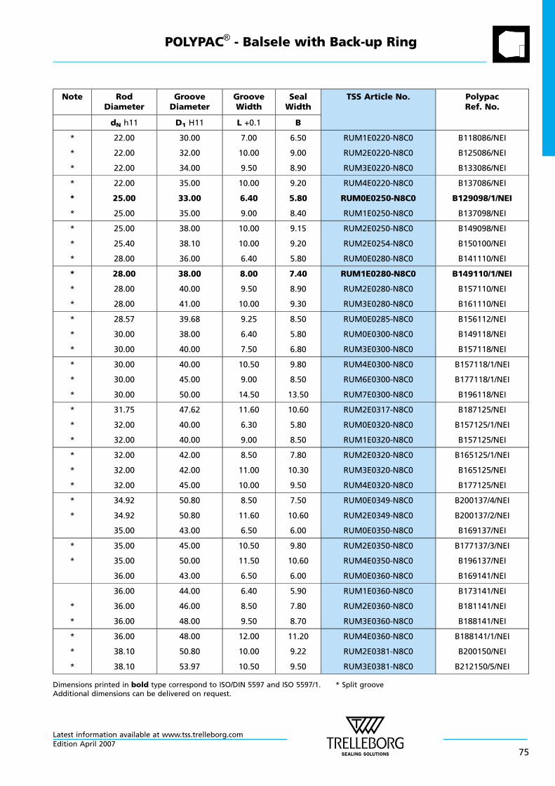
Note RodDiameter
GrooveDiameter
GrooveWidth
SealWidth
TSS Article No. PolypacRef. No.
dN h11 D1 H11 L +0.1 B
*
*
*
22.00
22.00
22.00
30.00
32.00
34.00
7.00
10.00
9.50
6.50
9.00
8.90
RUM1E0220-N8C0
RUM2E0220-N8C0
RUM3E0220-N8C0
B118086/NEI
B125086/NEI
B133086/NEI
*
*
*
22.00
25.00
25.00
35.00
33.00
35.00
10.00
6.40
9.00
9.20
5.80
8.40
RUM4E0220-N8C0
RUM0E0250-N8C0
RUM1E0250-N8C0
B137086/NEI
B129098/1/NEI
B137098/NEI
*
*
*
25.00
25.40
28.00
38.00
38.10
36.00
10.00
10.00
6.40
9.15
9.20
5.80
RUM2E0250-N8C0
RUM2E0254-N8C0
RUM0E0280-N8C0
B149098/NEI
B150100/NEI
B141110/NEI
*
*
*
28.00
28.00
28.00
38.00
40.00
41.00
8.00
9.50
10.00
7.40
8.90
9.30
RUM1E0280-N8C0
RUM2E0280-N8C0
RUM3E0280-N8C0
B149110/1/NEI
B157110/NEI
B161110/NEI
*
*
*
28.57
30.00
30.00
39.68
38.00
40.00
9.25
6.40
7.50
8.50
5.80
6.80
RUM0E0285-N8C0
RUM0E0300-N8C0
RUM3E0300-N8C0
B156112/NEI
B149118/NEI
B157118/NEI
*
*
*
30.00
30.00
30.00
40.00
45.00
50.00
10.50
9.00
14.50
9.80
8.50
13.50
RUM4E0300-N8C0
RUM6E0300-N8C0
RUM7E0300-N8C0
B157118/1/NEI
B177118/1/NEI
B196118/NEI
*
*
*
31.75
32.00
32.00
47.62
40.00
40.00
11.60
6.30
9.00
10.60
5.80
8.50
RUM2E0317-N8C0
RUM0E0320-N8C0
RUM1E0320-N8C0
B187125/NEI
B157125/1/NEI
B157125/NEI
*
*
*
32.00
32.00
32.00
42.00
42.00
45.00
8.50
11.00
10.00
7.80
10.30
9.50
RUM2E0320-N8C0
RUM3E0320-N8C0
RUM4E0320-N8C0
B165125/1/NEI
B165125/NEI
B177125/NEI
*
*
34.92
34.92
35.00
50.80
50.80
43.00
8.50
11.60
6.50
7.50
10.60
6.00
RUM0E0349-N8C0
RUM2E0349-N8C0
RUM0E0350-N8C0
B200137/4/NEI
B200137/2/NEI
B169137/NEI
*
*
35.00
35.00
36.00
45.00
50.00
43.00
10.50
11.50
6.50
9.80
10.60
6.00
RUM2E0350-N8C0
RUM4E0350-N8C0
RUM0E0360-N8C0
B177137/3/NEI
B196137/NEI
B169141/NEI
*
*
36.00
36.00
36.00
44.00
46.00
48.00
6.40
8.50
9.50
5.90
7.80
8.70
RUM1E0360-N8C0
RUM2E0360-N8C0
RUM3E0360-N8C0
B173141/NEI
B181141/NEI
B188141/NEI
*
*
*
36.00
38.10
38.10
48.00
50.80
53.97
12.00
10.00
10.50
11.20
9.22
9.50
RUM4E0360-N8C0
RUM2E0381-N8C0
RUM3E0381-N8C0
B188141/1/NEI
B200150/NEI
B212150/5/NEI
Dimensions printed in bold type correspond to ISO/DIN 5597 and ISO 5597/1. * Split grooveAdditional dimensions can be delivered on request.
POLYPAC® - Balsele with Back-up Ring
Latest information available at www.tss.trelleborg.comEdition April 2007
75
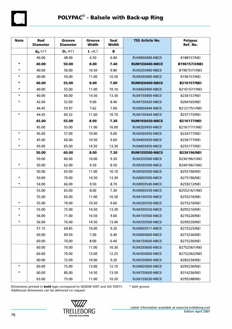
Note RodDiameter
GrooveDiameter
GrooveWidth
SealWidth
TSS Article No. PolypacRef. No.
dN h11 D1 H11 L +0.1 B
*
*
40.00
40.00
40.00
48.00
50.00
50.00
6.50
8.00
10.50
6.00
7.40
9.80
RUM0E0400-N8C0
RUM1E0400-N8C0
RUM2E0400-N8C0
B188157/NEI
B196157/3/NEI
B196157/1/NEI
*
*
*
40.00
40.00
40.00
50.00
55.00
55.00
11.00
8.00
11.00
10.30
7.00
10.10
RUM3E0400-N8C0
RUM5E0400-N8C0
RUM6E0400-N8C0
B196157/NEI
B216157/NEI
B216157/1/NEI
*
*
40.00
42.00
44.45
60.00
52.00
53.97
14.50
9.00
7.62
13.30
8.40
7.00
RUM7E0400-N8C0
RUM1E0420-N8C0
RUM0E0444-N8C0
B236157/NEI
B204165/NEI
B212175/1/NEI
* 44.45
45.00
45.00
60.32
55.00
55.00
11.60
8.00
11.00
10.70
7.30
10.00
RUM1E0444-N8C0
RUM1E0450-N8C0
RUM2E0450-N8C0
B237175/NEI
B216177/NEI
B216177/1/NEI
*
*
*
45.00
45.00
45.00
57.00
60.00
65.00
10.00
10.50
14.50
9.00
9.60
13.30
RUM3E0450-N8C0
RUM4E0450-N8C0
RUM6E0450-N8C0
B224177/NEI
B236177/NEI
B255177/NEI
*
50.00
50.00
50.00
60.00
60.00
62.00
8.00
10.00
9.50
7.30
9.30
8.50
RUM1E0500-N8C0
RUM2E0500-N8C0
RUM3E0500-N8C0
B236196/NEI
B236196/1/NEI
B244196/1/NEI
*
*
50.00
50.00
54.00
65.00
70.00
66.00
11.00
14.50
9.50
10.10
13.30
8.70
RUM5E0500-N8C0
RUM6E0500-N8C0
RUM0E0540-N8C0
B255196/NEI
B275196/NEI
B259212/NEI
*
55.00
55.00
55.00
65.00
65.00
70.00
8.00
11.00
10.50
7.30
10.30
9.60
RUM0E0550-N8C0
RUM1E0550-N8C0
RUM2E0550-N8C0
B255216/1/NEI
B255216/NEI
B275216/NEI
*
*
*
55.00
56.00
56.00
75.00
71.00
76.00
14.50
10.50
14.50
13.30
9.60
13.40
RUM3E0550-N8C0
RUM1E0560-N8C0
RUM2E0560-N8C0
B295216/NEI
B279220/NEI
B299220/NEI
57.15
60.00
60.00
69.85
69.50
70.00
10.00
7.00
8.00
9.20
6.40
6.40
RUM0E0571-N8C0
RUM0E0600-N8C0
RUM1E0600-N8C0
B275225/NEI
B273236/NEI
B275236/NEI
60.00
60.00
60.00
70.00
70.00
72.00
11.00
13.00
10.00
10.30
12.25
9.20
RUM2E0600-N8C0
RUM3E0600-N8C0
RUM5E0600-N8C0
B275236/1/NEI
B275236/2/NEI
B283236/NEI
*
*
60.00
60.00
63.00
75.00
80.00
75.00
13.00
14.50
11.00
12.10
13.50
10.20
RUM6E0600-N8C0
RUM7E0600-N8C0
RUM1E0630-N8C0
B295236/NEI
B314236/NEI
B295248/NEI
Dimensions printed in bold type correspond to ISO/DIN 5597 and ISO 5597/1. * Split grooveAdditional dimensions can be delivered on request.
POLYPAC® - Balsele with Back-up Ring
Latest information available at www.tss.trelleborg.com
76Edition April 2007
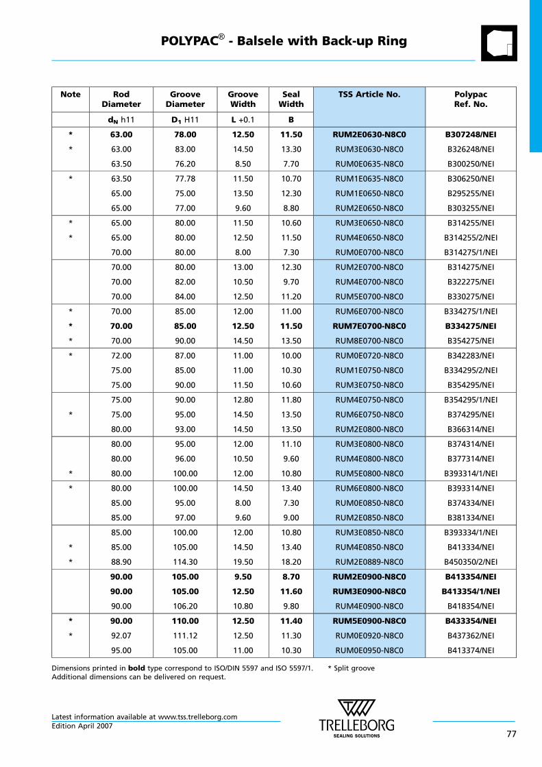
Note RodDiameter
GrooveDiameter
GrooveWidth
SealWidth
TSS Article No. PolypacRef. No.
dN h11 D1 H11 L +0.1 B
*
*
63.00
63.00
63.50
78.00
83.00
76.20
12.50
14.50
8.50
11.50
13.30
7.70
RUM2E0630-N8C0
RUM3E0630-N8C0
RUM0E0635-N8C0
B307248/NEI
B326248/NEI
B300250/NEI
* 63.50
65.00
65.00
77.78
75.00
77.00
11.50
13.50
9.60
10.70
12.30
8.80
RUM1E0635-N8C0
RUM1E0650-N8C0
RUM2E0650-N8C0
B306250/NEI
B295255/NEI
B303255/NEI
*
*
65.00
65.00
70.00
80.00
80.00
80.00
11.50
12.50
8.00
10.60
11.50
7.30
RUM3E0650-N8C0
RUM4E0650-N8C0
RUM0E0700-N8C0
B314255/NEI
B314255/2/NEI
B314275/1/NEI
70.00
70.00
70.00
80.00
82.00
84.00
13.00
10.50
12.50
12.30
9.70
11.20
RUM2E0700-N8C0
RUM4E0700-N8C0
RUM5E0700-N8C0
B314275/NEI
B322275/NEI
B330275/NEI
*
*
*
70.00
70.00
70.00
85.00
85.00
90.00
12.00
12.50
14.50
11.00
11.50
13.50
RUM6E0700-N8C0
RUM7E0700-N8C0
RUM8E0700-N8C0
B334275/1/NEI
B334275/NEI
B354275/NEI
* 72.00
75.00
75.00
87.00
85.00
90.00
11.00
11.00
11.50
10.00
10.30
10.60
RUM0E0720-N8C0
RUM1E0750-N8C0
RUM3E0750-N8C0
B342283/NEI
B334295/2/NEI
B354295/NEI
*
75.00
75.00
80.00
90.00
95.00
93.00
12.80
14.50
14.50
11.80
13.50
13.50
RUM4E0750-N8C0
RUM6E0750-N8C0
RUM2E0800-N8C0
B354295/1/NEI
B374295/NEI
B366314/NEI
*
80.00
80.00
80.00
95.00
96.00
100.00
12.00
10.50
12.00
11.10
9.60
10.80
RUM3E0800-N8C0
RUM4E0800-N8C0
RUM5E0800-N8C0
B374314/NEI
B377314/NEI
B393314/1/NEI
* 80.00
85.00
85.00
100.00
95.00
97.00
14.50
8.00
9.60
13.40
7.30
9.00
RUM6E0800-N8C0
RUM0E0850-N8C0
RUM2E0850-N8C0
B393314/NEI
B374334/NEI
B381334/NEI
*
*
85.00
85.00
88.90
100.00
105.00
114.30
12.00
14.50
19.50
10.80
13.40
18.20
RUM3E0850-N8C0
RUM4E0850-N8C0
RUM2E0889-N8C0
B393334/1/NEI
B413334/NEI
B450350/2/NEI
90.00
90.00
90.00
105.00
105.00
106.20
9.50
12.50
10.80
8.70
11.60
9.80
RUM2E0900-N8C0
RUM3E0900-N8C0
RUM4E0900-N8C0
B413354/NEI
B413354/1/NEI
B418354/NEI
*
*
90.00
92.07
95.00
110.00
111.12
105.00
12.50
12.50
11.00
11.40
11.30
10.30
RUM5E0900-N8C0
RUM0E0920-N8C0
RUM0E0950-N8C0
B433354/NEI
B437362/NEI
B413374/NEI
Dimensions printed in bold type correspond to ISO/DIN 5597 and ISO 5597/1. * Split grooveAdditional dimensions can be delivered on request.
POLYPAC® - Balsele with Back-up Ring
Latest information available at www.tss.trelleborg.comEdition April 2007
77
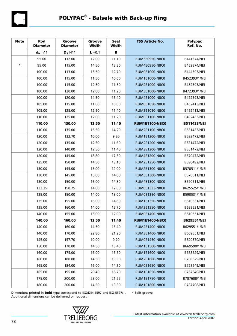
Note RodDiameter
GrooveDiameter
GrooveWidth
SealWidth
TSS Article No. PolypacRef. No.
dN h11 D1 H11 L +0.1 B
*
95.00
95.00
100.00
112.00
115.00
113.00
12.00
14.50
13.50
11.10
13.30
12.70
RUM3E0950-N8C0
RUM4E0950-N8C0
RUM0E1000-N8C0
B441374/NEI
B452374/NEI
B444393/NEI
100.00
100.00
100.00
115.00
115.00
120.00
11.50
12.50
12.00
10.60
11.50
11.20
RUM1E1000-N8C0
RUM2E1000-N8C0
RUM3E1000-N8C0
B452393/1/NEI
B452393/NEI
B472393/1/NEI
100.00
105.00
105.00
120.00
115.00
125.00
14.50
11.00
12.50
13.40
10.00
11.40
RUM4E1000-N8C0
RUM0E1050-N8C0
RUM3E1050-N8C0
B472393/NEI
B452413/NEI
B492413/NEI
110.00
110.00
110.00
125.00
130.00
135.00
12.00
12.50
15.50
11.20
11.40
14.20
RUM0E1100-N8C0
RUM1E1100-N8C0
RUM2E1100-N8C0
B492433/NEI
B511433/NEI
B531433/NEI
120.00
120.00
120.00
132.70
135.00
140.00
10.00
12.50
12.50
9.20
11.60
11.40
RUM1E1200-N8C0
RUM2E1200-N8C0
RUM3E1200-N8C0
B522472/NEI
B531472/NEI
B551472/NEI
120.00
125.00
130.00
145.00
150.00
145.00
18.80
14.50
13.00
17.50
13.10
12.00
RUM4E1200-N8C0
RUM2E1250-N8C0
RUM2E1300-N8C0
B570472/NEI
B590492/NEI
B570511/1/NEI
130.00
130.00
133.35
145.00
150.00
158.75
15.00
16.00
14.00
14.00
14.80
12.60
RUM3E1300-N8C0
RUM4E1300-N8C0
RUM0E1333-N8C0
B570511/NEI
B590511/NEI
B625525/1/NEI
135.00
135.00
135.00
150.00
155.00
160.00
14.00
16.00
14.00
13.00
14.80
12.70
RUM0E1350-N8C0
RUM1E1350-N8C0
RUM2E1350-N8C0
B590531/1/NEI
B610531/NEI
B629531/NEI
140.00
140.00
140.00
155.00
160.00
160.00
13.00
12.50
14.50
12.00
11.40
13.40
RUM0E1400-N8C0
RUM1E1400-N8C0
RUM2E1400-N8C0
B610551/NEI
B629551/NEI
B629551/1/NEI
140.00
145.00
150.00
170.00
157.70
170.00
22.80
10.00
14.50
21.20
9.20
13.40
RUM3E1400-N8C0
RUM0E1450-N8C0
RUM1E1500-N8C0
B669551/NEI
B620570/NEI
B669590/1/NEI
160.00
160.00
165.00
175.00
180.00
184.00
16.00
14.50
16.00
15.50
13.30
14.80
RUM1E1600-N8C0
RUM2E1600-N8C0
RUM0E1650-N8C0
B688629/NEI
B708629/NEI
B728649/NEI
165.00
175.00
180.00
195.00
200.00
200.00
20.40
23.00
14.50
18.70
21.55
13.30
RUM1E1650-N8C0
RUM1E1750-N8C0
RUM1E1800-N8C0
B767649/NEI
B787688/1/NEI
B787708/NEI
Dimensions printed in bold type correspond to ISO/DIN 5597 and ISO 5597/1. * Split grooveAdditional dimensions can be delivered on request.
POLYPAC® - Balsele with Back-up Ring
Latest information available at www.tss.trelleborg.com
78Edition April 2007
Note RodDiameter
GrooveDiameter
GrooveWidth
SealWidth
TSS Article No. PolypacRef. No.
dN h11 D1 H11 L +0.1 B
180.00
190.00
198.00
210.00
210.00
208.00
20.50
14.50
12.00
18.90
13.40
11.30
RUM2E1800-N8C0
RUM0E1900-N8C0
RUM0E1980-N8C0
B826708/1/NEI
B826748/NEI
B819779/NEI
200.00
210.00
210.00
220.00
230.00
240.00
14.50
14.50
22.50
13.30
13.30
21.00
RUM0E2000-N8C0
RUM0E2100-N8C0
RUM1E2100-N8C0
B866787/NEI
B905826/NEI
B944826/NEI
220.00
230.00
500.00
250.00
260.00
540.00
20.50
20.50
35.00
18.90
19.00
32.80
RUM0E2200-N8C0
RUM0E2300-N8C0
RUM0E5000-N8C0
B984866/NEI
B1023905/NEI
B21261968/NEI
530.00
640.00
702.00
570.00
680.00
752.40
25.00
25.00
30.00
23.00
23.00
27.50
RUM0E5300-N8C0
RUM0E6400-N8C0
RUM0E7020-N8C0
B22442086/NEI
B26772519/NEI
B29612764/NEI
760.00
785.00
845.00
820.00
845.00
905.00
35.00
35.00
35.00
32.00
32.00
32.00
RUM0E7600-N8C0
RUM0E7850-N8C0
RUM0E8450-N8C0
B32282992/NEI
B33273090/NEI
B35633327/NEI
921.00
1040.00
1195.00
981.00
1110.00
1265.00
35.00
35.00
35.00
32.00
32.00
32.00
RUM0E9210-N8C0
RUM0X1040-N8C0
RUM0X1195-N8C0
B38623626/NEI
B43704094/NEI
B49804705/NEI
Dimensions printed in bold type correspond to ISO/DIN 5597 and ISO 5597/1. * Split grooveAdditional dimensions can be delivered on request.
POLYPAC® - Balsele with Back-up Ring
Latest information available at www.tss.trelleborg.comEdition April 2007
79
POLYPAC® - Balsele with Back-up Ring
Latest information available at www.tss.trelleborg.com
80Edition April 2007
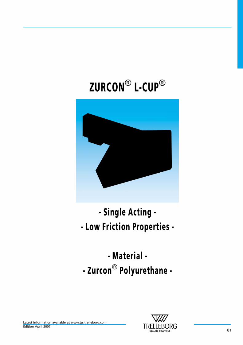
ZURCON® L-CUP®
- Single Acting -
- Low Friction Properties -
- Material -
- Zurcon® Polyurethane -
Latest information available at www.tss.trelleborg.comEdition April 2007
81

Latest information available at www.tss.trelleborg.com
82Edition April 2007
n Zurcon® L-Cup®
Introduction
The rod sealing system is the most critical part of ahydraulic cylinder. Therefore it is expected that a rodsealing system performs under leak-free conditions in thestatic and dynamic state. Moreover it has to fulfil thelifetime of several thousand hours.
To meet these requirements, Trelleborg Sealing Solutionshas developed the Zurcon® L-Cup®*, a highly effective andinnovative rod sealing component.
*Patent for: Europe No. EP 0724693*Patent for: US No. 5,649,711*Patent for: China No. ZL 94193869.7
Zurcon® L-Cup® is a trade name.
Description
Zurcon® L-Cup® is a single acting polyurethane rod sealwith a unique design offering a hydrodynamic back-pumping ability over the complete working pressurerange. The pressure-independent, hydrodynamic sealingability of this new sealing element requires no lubricationreservoir in the sealing area and ensures a constant andcontrolled pressure distribution over a wide pressurerange.
The advantages of the Zurcon® L-Cup® design lead to thefollowing improved properties:
Advantages
- Hydrodynamic back-pumping ability over the completeworking pressure range
- Low friction and therefore a reduction of heat generated
- Low breakout force even after a long period of non-operation
- Very low stick-slip
- Low increase in friction at increasing pressure
- High extrusion resistance
- Optimum geometry of the static sealing lip for highersealing ability
- No entrapped oil and grease between seal and groove(due to notches)
- No pressure build-up between seal and groove OD
- Long service life
The Zurcon® L-Cup® was designed in accordance withcustomers’ demands.
- Groove dimensions according to ISO 5597 Part 2
- Interchangeable with existing U-Cup grooves
- Installation into closed grooves
- Wear and extrusion resistant high-performancepolyurethane
Application Examples
Zurcon® L-Cup® can be used in all applications in whichpreviously a conventional U-Cup was applied, such as:
- Fork lifts
- Agricultural machines
- Light and medium mobile hydraulics
- Industrial hydraulics
- Machine tools
- Injection moulding machines
- hydraulic presses.
Another preferred solution for tandem rod sealing systemsis the combination with the Turcon® Stepseal® 2K asprimary seal and L-Cup® as secondary seal, in conjunctionwith a double acting scraper.
Technical Data
Operating conditions
Pressure: Up to 40 MPa
Velocity: Up to 0.5 m/s
Temperature: -35°C to +110°C
Media: Hydraulic fluids based onmineral oil
Important Note:The above data are maximum values and cannotbe used at the same time. e.g. the maximumoperating speed depends on material type,pressure, temperature and gap value.Temperature range also dependent on medium.
Materials
Zurcon® Z20
Special polyurethane 93 Shore A
Colour: turquoise
Zurcon® L-Cup®
Latest information available at www.tss.trelleborg.comEdition April 2007
83
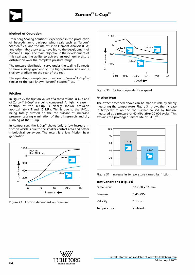
Method of Operation
Trelleborg Sealing Solutions’ experience in the productionof hydrodynamic back-pumping seals such as Turcon®
Stepseal® 2K, and the use of Finite Element Analysis (FEA)and other laboratory tests have led to the development ofZurcon® L-Cup®. The main objective in the development ofthis seal was the ability to achieve an optimum pressuredistribution over the complete pressure range.
The pressure distribution curve under the sealing lip needsto have a steep gradient on the high-pressure side and ashallow gradient on the rear of the seal.
The operating principles and function of Zurcon® L-Cup® issimilar to the well-known Turcon® Stepseal® 2K.
Friction
In Figure 29 the friction values of a conventional U-Cup andof Zurcon® L-Cup® are being compared. A high increase infriction of the U-Cup is clearly shown betweenapproximately 5 and 15 MPa. This is due to the U-Cupbeing totally pressed on the rod surface at increasedpressure, causing elimination of the oil reservoir and dryrunning of the U-Cup.
In comparison, the L-Cup® shows only a low increase infriction which is due to the smaller contact area and bettertribological behaviour. The result is a low friction heatgeneration.
0 5 10 MPa 200
300
600
900
N
1500
Pressure
U-Cup
L-Cup®
HLP 46Rod Ø45 mm
Fric
tio
nfo
rce
Figure 29 Friction dependent on pressure
0.01 0.02 0.05 m/s 0.40
400
800
N
1600
Speed
0.1
U-Cup 1 U-Cup 2
L-Cup®
Fric
tio
nfo
rce
Figure 30 Friction dependent on speed
Friction Heat
The effect described above can be made visible by simplymeasuring the temperature. Figure 31 shows the increasein temperature on the rod surface caused by friction,measured at a pressure of 40 MPa after 20 000 cycles. Thisexplains the prolonged service life of L-Cup®.
0
20
40
60
°C
100
U-Cup
L-Cup®
Figure 31 Increase in temperature caused by friction
Test Conditions (Fig. 31)
Dimension: 50 x 60 x 11 mm
Pressure: 0/40 MPa
Velocity: 0.1 m/s
Temperature: ambient
Zurcon® L-Cup®
Latest information available at www.tss.trelleborg.com
84Edition April 2007
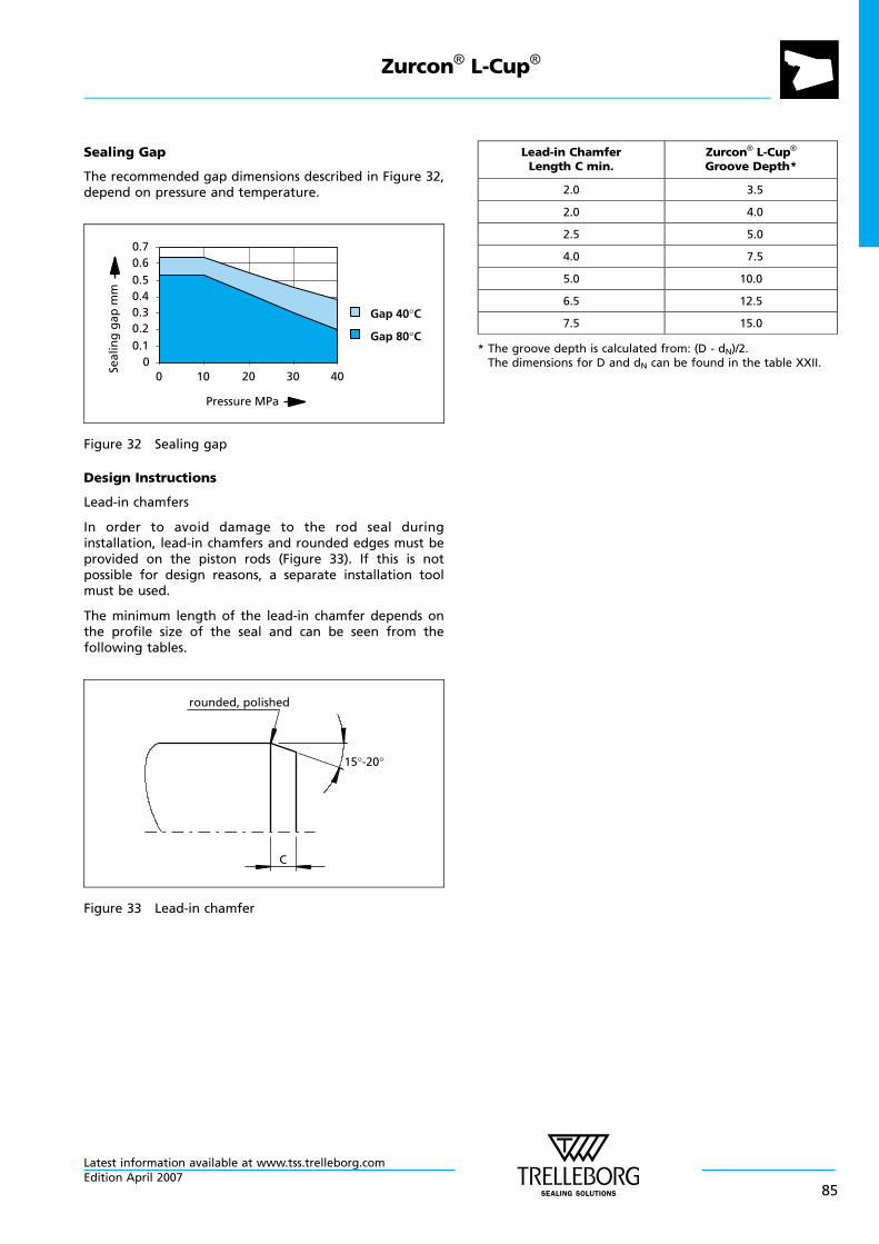
Sealing Gap
The recommended gap dimensions described in Figure 32,depend on pressure and temperature.
00.1
0.20.30.40.5
0.60.7
0 10 20 30 40
Pressure MPa
Gap 40°C
Gap 80°C
Seal
ing
gap
mm
Figure 32 Sealing gap
Design Instructions
Lead-in chamfers
In order to avoid damage to the rod seal duringinstallation, lead-in chamfers and rounded edges must beprovided on the piston rods (Figure 33). If this is notpossible for design reasons, a separate installation toolmust be used.
The minimum length of the lead-in chamfer depends onthe profile size of the seal and can be seen from thefollowing tables.
C
rounded, polished
15°-20°
Figure 33 Lead-in chamfer
Lead-in ChamferLength C min.
Zurcon® L-Cup®
Groove Depth*
2.0 3.5
2.0 4.0
2.5 5.0
4.0 7.5
5.0 10.0
6.5 12.5
7.5 15.0
* The groove depth is calculated from: (D - dN)/2.The dimensions for D and dN can be found in the table XXII.
Zurcon® L-Cup®
Latest information available at www.tss.trelleborg.comEdition April 2007
85
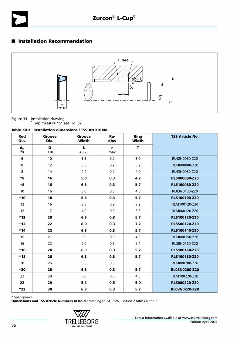
n Installation Recommendation
T
dN
r max.
D
L
S*
Figure 34 Installation drawing* Gap measure “S“ see Fig. 32
Table XXII Installation dimensions / TSS Article No.
RodDia.
GrooveDia.
GrooveWidth
Ra-dius
RingWidth
TSS Article No.
dNf8
DH10
L+0.25
rmax
T
6
8
8
10
12
14
3.3
3.6
4.4
0.2
0.2
0.2
3.0
3.2
4.0
RL42N0060-Z20
RLM000080-Z20
RL43N0080-Z20
*8
*8
10
16
16
16
5.0
6.3
5.0
0.3
0.3
0.3
4.2
5.7
4.5
RLS400080-Z20
RLS100080-Z20
RL03N0100-Z20
*10
12
12
18
16
17
6.3
3.6
4.0
0.3
0.2
0.3
5.7
3.2
3.6
RLS100100-Z20
RLM100120-Z20
RLM000120-Z20
*12
*12
*14
20
22
22
6.3
8.0
6.3
0.3
0.3
0.3
5.7
7.2
5.7
RLS100120-Z20
RLS500120-Z20
RLS100140-Z20
15
16
*16
21
22
24
5.0
6.0
6.3
0.3
0.3
0.3
4.5
5.4
5.7
RLM000150-Z20
RL38N0160-Z20
RLS100160-Z20
*18
20
*20
26
26
28
6.3
5.5
6.3
0.3
0.3
0.3
5.7
5.0
5.7
RLS100180-Z20
RLM000200-Z20
RL08N0200-Z20
22
22
*22
28
29
30
5.0
5.6
6.3
0.3
0.5
0.3
4.5
5.0
5.7
RLM100220-Z20
RLS000220-Z20
RL08N0220-Z20
* Split grooveDimensions and TSS Article Numbers in bold according to ISO 5597, Edition 2 tables 4 and 5.
Zurcon® L-Cup®
Latest information available at www.tss.trelleborg.com
86Edition April 2007
RodDia.
GrooveDia.
GrooveWidth
Ra-dius
RingWidth
TSS Article No.
dNf8
DH10
L+0.25
rmax
T
25
25
*25
33
33
35
7.2
6.3
8.0
0.3
0.3
0.3
8.0
5.7
7.2
RL10N0250-Z20
RLS100250-Z20
RLS500250-Z20
28
*28
30
36
38
38
6.3
8.0
6.3
0.5
0.3
0.3
5.7
7.2
5.7
RL08N0280-Z20
RL14N0280-Z20
RLM000300-Z20
30
30
30
40
38
40
7.2
8.0
11.5
0.3
0.3
0.3
8.0
7.2
10.0
RL14N0300-Z20
RL10N0300-Z20
RL17N0300-Z20
32
32
35
40
42
43
7.0
8.0
6.3
0.3
0.3
0.3
6.3
7.2
5.7
RLM000320-Z20
RL14N0320-Z20
RLM000350-Z20
35
36
36
45
44
46
11.0
6.3
8.0
0.3
0.5
0.3
9.9
5.7
7.2
RL17N0350-Z20
RLS100360-Z20
RLS500360-Z20
36
38
40
46
48
48
10.0
11.0
7.0
0.3
0.3
0.3
9.0
9.9
6.3
RL16N0360-Z20
RL17N0380-Z20
RL09N0400-Z20
40
40
42
50
50
52
8.0
10.0
8.0
0.3
0.3
0.3
7.2
9.0
7.2
RL14N0400-Z20
RL16N0400-Z20
RL14N0420-Z20
42
45
45
52
53
55
10.0
8.0
8.0
0.3
0.3
0.3
9.0
7.2
7.2
RL16N0420-Z20
RL10N0450-Z20
RL14N0450-Z20
48
50
50
60
58
60
11.0
9.0
8.0
0.3
0.3
0.3
9.9
8.1
7.2
RL36N0480-Z20
RL11N0500-Z20
RL14N0500-Z20
50
50
55
60
65
63
10.0
12.5
9.0
0.3
0.4
0.3
9.0
11.3
8.1
RL16N0500-Z20
RL26N0500-Z20
RL11N0550-Z20
55
*56
60
65
71
68
10.0
12.5
9.0
0.3
0.4
0.3
9.0
11.3
8.1
RL16N0550-Z20
RL26N0560-Z20
RL11N0600-Z20
* Split grooveDimensions and TSS Article Numbers in bold according to ISO 5597, Edition 2 tables 4 and 5.
Zurcon® L-Cup®
Latest information available at www.tss.trelleborg.comEdition April 2007
87
RodDia.
GrooveDia.
GrooveWidth
Ra-dius
RingWidth
TSS Article No.
dNf8
DH10
L+0.25
rmax
T
60
60
63
70
70
78
8.5
10.0
12.5
0.3
0.3
0.4
8.0
9.0
11.3
RL14N0600-Z20
RL16N0600-Z20
RL26N0630-Z20
65
65
68
73
75
78
7.0
10.0
11.0
0.3
0.3
0.3
6.3
9.0
9.9
RL09N0650-Z20
RL16N0650-Z20
RL17N0680-Z20
70
70
75
80
85
85
10.0
12.5
10.0
0.3
0.4
0.3
9.0
11.3
9.0
RL16N0700-Z20
RL26N0700-Z20
RL16N0750-Z20
75
80
80
90
95
100
12.5
12.5
16.0
0.3
0.4
0.6
11.3
11.3
14.4
RL26N0750-Z20
RL26N0800-Z20
RL30N0800-Z20
85
90
100
100
105
120
13.1
12.5
12.5
0.4
0.4
0.6
11.8
11.3
10.8
RL27N0850-Z20
RL26N0900-Z20
RLSA01000-Z20
100
105
110
120
125
130
16.0
12.5
16.0
0.6
0.6
0.6
14.4
10.8
14.4
RL30N1000-Z20
RL29N1050-Z20
RL30N1100-Z20
115
119
120
135
134
135
16.0
9.4
12.5
0.6
0.4
0.4
14.4
8.1
11.3
RL30N1150-Z20
RL22N1190-Z20
RL26N1200-Z20
120
125
125
140
140
145
16.0
12.0
16.0
0.6
0.4
0.6
14.4
10.8
14.4
RL30N1200-Z20
RL25N1250-Z20
RL30N1250-Z20
130
135
140
150
155
160
16.0
16.0
16.0
0.6
0.6
0.6
14.4
14.4
14.4
RL30N1300-Z20
RL30N1350-Z20
RL30N1400-Z20
148
150
150
168
170
170
16.5
12.5
16.0
0.6
0.6
0.6
16.0
10.8
14.4
RL30N1480-Z20
RL29N1500-Z20
RL30N1500-Z20
155
160
160
175
180
185
16.0
16.0
16.0
0.6
0.6
0.8
14.4
14.4
13.5
RL30N1550-Z20
RL30N1600-Z20
RLSC01600-Z20
* Split grooveDimensions and TSS Article Numbers in bold according to ISO 5597, Edition 2 tables 4 and 5.
Zurcon® L-Cup®
Latest information available at www.tss.trelleborg.com
88Edition April 2007
RodDia.
GrooveDia.
GrooveWidth
Ra-dius
RingWidth
TSS Article No.
dNf8
DH10
L+0.25
rmax
T
180
195
200
205
220
220
20.0
20.0
16.0
0.8
0.6
0.6
18.0
18.0
14.4
RL32N1800-Z20
RL32N1950-Z20
RL30N2000-Z20
200
220
250
225
250
280
20.0
20.0
20.0
0.8
0.8
0.8
18.0
16.2
16.2
RL32N2000-Z20
RLSE02200-Z20
RLSE02500-Z20
* Split grooveDimensions and TSS Article Numbers in bold according to ISO 5597, Edition 2 tables 4 and 5.
Zurcon® L-Cup®
Latest information available at www.tss.trelleborg.comEdition April 2007
89
Zurcon® L-Cup®
Latest information available at www.tss.trelleborg.com
90Edition April 2007
ZURCON® U-CUP RU0
- Single Acting U-Cup -
- Asymmetric, Single Lip -
- Material -
- Zurcon® Polyurethane -
Latest information available at www.tss.trelleborg.comEdition April 2007
91

Latest information available at www.tss.trelleborg.com
92Edition April 2007
n U-Cup RU0
Description
Today U-Cups are used primarily as seals for piston rods inhydraulic cylinders. U-Cups in polyurethane are provenelements, due to their good mechanical properties, forstandard cylinder construction, particularly for mobilehydraulics under rough operating conditions.
The U-Cup is a single lip seal.
Type RU0
The U-Cup type RU0 is installed as a single-acting single-lipcompact seal. The seal is installed with a simple snap fittingand seals statically on the outside diameter via a fixed seat.It has an asymmetric seal lip profile with shortened innerlip. This form can absorb deflections in the piston rod moreeasily than, e.g. U-Cup Form RU2 with its more rigid lipgeometry. In pressure-free state, it exhibits lower frictionalforces than double-lipped U-Cups.
p
Figure 35 U-Cup, type RU0
Method of Operation
The sealing effect of the U-Cup comes from the intrinsicpreload of the seal body and from the compression of theseal lips during installation. In operating condition, theradial mechanical contact forces are superimposed by thesystem pressure.
At low stroke speeds, U-Cups can tend to have a stick-slipeffect due to an inadequate lubrication film formation inthe seal clearance and to their material properties. Thisbehaviour corresponds to the Stribeck curve described inthe relevant literature.
Advantages
- Good pressure-adapted sealing effect
- Unaffected by high loads and deflections of the pistonrod
- Good resistance to clearance extrusion
- Simple installation
- Lower friction in the low pressure range compared withdouble-lipped versions.
Technical Data
Operating pressure: Max. 40 MPa
Speed: Up to 0.5 m/s
Temperature: Use in mineral oils:-35°C to + 110°C
Media: Mineral oil-based hydraulicfluids.
Important Note:The above data are maximum values and cannotbe used at the same time. e.g. the maximumoperating speed depends on material type,pressure, temperature and gap value.Temperature range also dependent on medium.
Seal clearance
Guide values for the radial clearance between rod andgland in relation to the operating pressure and roddiameter can be found in Table XXIII.
Table XXIII Clearance
Operatingmax. Pressure
MPa
Radial ClearanceS max.
dN <60 mm dN >60 mm
5 0.40 0.50
10 0.30 0.40
20 0.20 0.30
30 0.15 0.20
40 0.10 0.15
The values for S max given in this table apply to all types for thelow-pressure side of the U-Cup. They are designed for an operatingtemperature of 60°C.
Material
Zurcon®: Z20Special polyurethane: 93 Shore AColour: turquoise
Zurcon® U-Cup RU0
Latest information available at www.tss.trelleborg.comEdition April 2007
93
n Installation Recommendation
B
r max. 0.3
S
L
D1
dN
Figure 36 Installation drawingDimensions “S“ see Table XXIII
Ordering Example
U-Cup Type RU0Rod diameter: dN = 30.0 mmGroove diameter: D1 = 40.0 mmGroove width: L = 11.0 mmTSS Part No.: RU0000300 -
Material
Standard Zurcon®: Z20Special polyurethane: 93 Shore AColour: turquoise
Material code
TSS Series No.
TSS Article No. Z20
Rod diameter x 10
RU00
Quality Index (Standard)
-
Type (Standard)
0 0300
Table XXIV Installation dimensions / TSS Part No.
Note RodDiameter
GrooveDiameter
GrooveWidth
SealWidth
TSS Part No.
dN f8/h9 D1 H10 L +0.2 B
*
*
*
6.0
8.0
10.0
14.0
16.0
18.0
6.3
6.3
6.3
5.7
5.7
5.7
RU0100060
RU0100080
RU0100100
*
*
*
10.0
12.0
12.0
20.0
20.0
22.0
8.0
6.4
8.0
7.2
5.7
7.2
RU0200100
RU0200120
RU0300120
*
*
*
14.0
14.0
15.0
22.0
24.0
23.0
6.3
8.0
6.3
5.7
7.2
5.7
RU0000140
RU0100140
RU0000150
Dimensions printed in bold type correspond to ISO/DIN 5597 and ISO 5597/1. * Split grooveAdditional dimensions can be delivered on request.
Zurcon® U-Cup RU0
Latest information available at www.tss.trelleborg.com
94Edition April 2007
Note RodDiameter
GrooveDiameter
GrooveWidth
SealWidth
TSS Part No.
dN f8/h9 D1 H10 L +0.2 B
*
*
*
16.0
16.0
18.0
24.0
26.0
26.0
6.3
8.0
6.3
5.7
7.2
5.7
RU0200160
RU0400160
RU0300180
*
*
*
18.0
20.0
20.0
28.0
28.0
30.0
8.0
6.3
8.0
7.2
5.7
7.2
RU0500180
RU0300200
RU0600200
*
*
*
22.0
22.0
24.0
30.0
32.0
34.0
6.4
8.0
8.0
5.7
7.2
7.2
RU0200220
RU0300220
RU0000240
*
25.0
25.0
28.0
33.0
35.0
36.0
6.3
8.0
6.3
5.7
7.2
5.7
RU0500250
RU0700250
RU0000280
*
*
28.0
28.0
30.0
38.0
43.0
40.0
8.0
12.5
6.3
7.2
11.5
5.7
RU0100280
RU0600280
RU0500300
30.0
32.0
35.0
40.0
42.0
45.0
8.0
8.0
8.0
7.2
7.2
7.2
RU0600300
RU0400320
RU0100350
*
36.0
36.0
36.0
44.0
46.0
51.0
6.4
8.0
12.5
5.3
7.0
11.5
RU0000360
RU0100360
RU0700360
*
40.0
40.0
45.0
50.0
55.0
53.0
8.0
12.5
6.3
7.2
11.5
5.7
RU0500400
RU0900400
RU0100450
*
45.0
45.0
50.0
55.0
60.0
60.0
8.0
12.5
8.0
7.2
11.5
7.2
RU0400450
RU0900450
RU0000500
50.0
55.0
56.0
65.0
65.0
71.0
12.5
8.0
12.5
11.5
7.2
11.5
RU0800500
RU0200550
RU0200560
*
56.0
63.0
63.0
76.0
78.0
83.0
16.0
12.5
16.0
15.0
11.5
15.0
RU0500560
RU0500630
RU0900630
70.0
70.0
80.0
85.0
90.0
95.0
12.5
16.0
12.5
11.5
15.0
11.5
RU0600700
RU0A00700
RU0600800
Dimensions printed in bold type correspond to ISO/DIN 5597 and ISO 5597/1. * Split grooveAdditional dimensions can be delivered on request.
Zurcon® U-Cup RU0
Latest information available at www.tss.trelleborg.comEdition April 2007
95
Note RodDiameter
GrooveDiameter
GrooveWidth
SealWidth
TSS Part No.
dN f8/h9 D1 H10 L +0.2 B
80.0
90.0
90.0
100.0
105.0
105.0
16.0
9.5
12.5
15.0
8.5
11.5
RU0B00800
RU0200900
RU0400900
90.0
100.0
100.0
110.0
120.0
125.0
16.0
16.0
20.0
15.0
15.0
19.0
RU0600900
RU0601000
RU0701000
110.0
110.0
120.0
130.0
135.0
140.0
16.0
20.0
16.0
15.0
19.0
15.0
RU0301100
RU0401100
RU0701200
125.0
125.0
140.0
145.0
150.0
160.0
16.0
20.0
16.0
15.0
19.0
15.0
RU0101250
RU0301250
RU0001400
140.0
160.0
200.0
165.0
185.0
225.0
20.0
20.0
20.0
19.0
19.0
19.0
RU0401400
RU0201600
RU0302000
280.0 310.0 25.0 24.0 RU0102800
Dimensions printed in bold type correspond to ISO/DIN 5597 and ISO 5597/1. * Split grooveAdditional dimensions can be delivered on request.
Zurcon® U-Cup RU0
Latest information available at www.tss.trelleborg.com
96Edition April 2007

ZURCON® U-CUP RU2
- Single Acting U-Cup -
- Asymmetric, Double Lip, Compact -
- Material -
- Zurcon® Polyurethane -
Latest information available at www.tss.trelleborg.comEdition April 2007
97

Latest information available at www.tss.trelleborg.com
98Edition April 2007
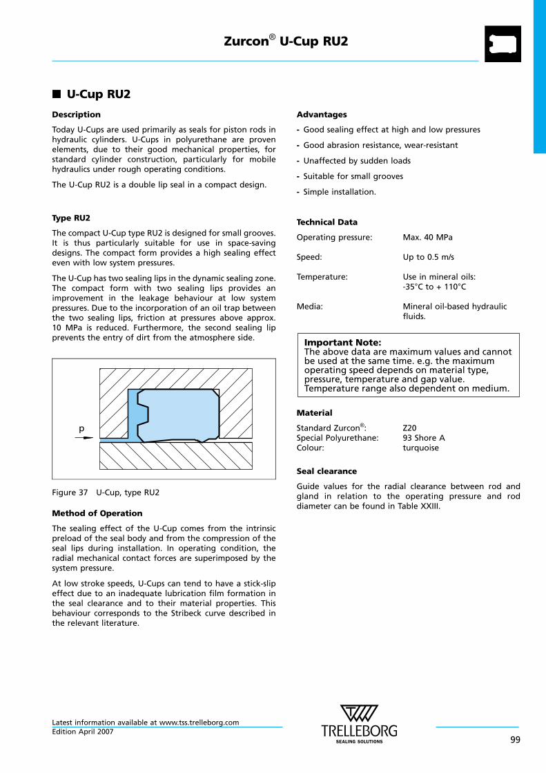
n U-Cup RU2
Description
Today U-Cups are used primarily as seals for piston rods inhydraulic cylinders. U-Cups in polyurethane are provenelements, due to their good mechanical properties, forstandard cylinder construction, particularly for mobilehydraulics under rough operating conditions.
The U-Cup RU2 is a double lip seal in a compact design.
Type RU2
The compact U-Cup type RU2 is designed for small grooves.It is thus particularly suitable for use in space-savingdesigns. The compact form provides a high sealing effecteven with low system pressures.
The U-Cup has two sealing lips in the dynamic sealing zone.The compact form with two sealing lips provides animprovement in the leakage behaviour at low systempressures. Due to the incorporation of an oil trap betweenthe two sealing lips, friction at pressures above approx.10 MPa is reduced. Furthermore, the second sealing lipprevents the entry of dirt from the atmosphere side.
p
Figure 37 U-Cup, type RU2
Method of Operation
The sealing effect of the U-Cup comes from the intrinsicpreload of the seal body and from the compression of theseal lips during installation. In operating condition, theradial mechanical contact forces are superimposed by thesystem pressure.
At low stroke speeds, U-Cups can tend to have a stick-slipeffect due to an inadequate lubrication film formation inthe seal clearance and to their material properties. Thisbehaviour corresponds to the Stribeck curve described inthe relevant literature.
Advantages
- Good sealing effect at high and low pressures
- Good abrasion resistance, wear-resistant
- Unaffected by sudden loads
- Suitable for small grooves
- Simple installation.
Technical Data
Operating pressure: Max. 40 MPa
Speed: Up to 0.5 m/s
Temperature: Use in mineral oils:-35°C to + 110°C
Media: Mineral oil-based hydraulicfluids.
Important Note:The above data are maximum values and cannotbe used at the same time. e.g. the maximumoperating speed depends on material type,pressure, temperature and gap value.Temperature range also dependent on medium.
Material
Standard Zurcon®: Z20Special Polyurethane: 93 Shore AColour: turquoise
Seal clearance
Guide values for the radial clearance between rod andgland in relation to the operating pressure and roddiameter can be found in Table XXIII.
Zurcon® U-Cup RU2
Latest information available at www.tss.trelleborg.comEdition April 2007
99
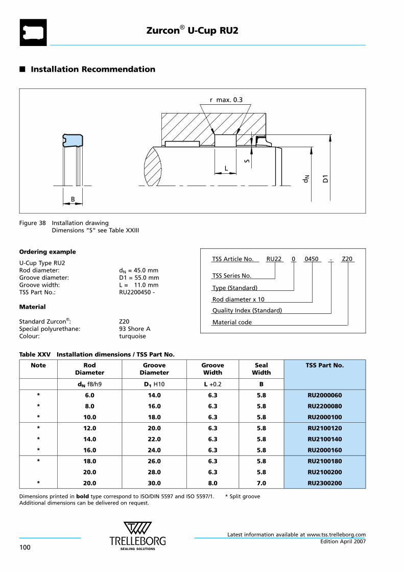
n Installation Recommendation
S
B
r max. 0.3
L
dN
D1
Figure 38 Installation drawingDimensions “S“ see Table XXIII
Ordering example
U-Cup Type RU2Rod diameter: dN = 45.0 mmGroove diameter: D1 = 55.0 mmGroove width: L = 11.0 mmTSS Part No.: RU2200450 -
Material
Standard Zurcon®: Z20Special polyurethane: 93 Shore AColour: turquoise
Material code
TSS Series No.
TSS Article No. Z20
Rod diameter x 10
RU22
Quality Index (Standard)
-
Type (Standard)
0 0450
Table XXV Installation dimensions / TSS Part No.
Note RodDiameter
GrooveDiameter
GrooveWidth
SealWidth
TSS Part No.
dN f8/h9 D1 H10 L +0.2 B
*
*
*
6.0
8.0
10.0
14.0
16.0
18.0
6.3
6.3
6.3
5.8
5.8
5.8
RU2000060
RU2200080
RU2000100
*
*
*
12.0
14.0
16.0
20.0
22.0
24.0
6.3
6.3
6.3
5.8
5.8
5.8
RU2100120
RU2100140
RU2000160
*
*
18.0
20.0
20.0
26.0
28.0
30.0
6.3
6.3
8.0
5.8
5.8
7.0
RU2100180
RU2100200
RU2300200
Dimensions printed in bold type correspond to ISO/DIN 5597 and ISO 5597/1. * Split grooveAdditional dimensions can be delivered on request.
Zurcon® U-Cup RU2
Latest information available at www.tss.trelleborg.com
100Edition April 2007
Note RodDiameter
GrooveDiameter
GrooveWidth
SealWidth
TSS Part No.
dN f8/h9 D1 H10 L +0.2 B
22.0
24.0
25.0
30.0
32.0
33.0
6.3
6.3
6.3
5.8
5.7
5.7
RU2300220
RU2000240
RU2000250
*
*
25.0
25.0
28.0
35.0
35.0
36.0
8.0
9.0
6.3
7.0
8.0
5.8
RU2400250
RU2500250
RU2000280
*
*
28.0
28.0
32.0
38.0
38.0
42.0
6.3
8.0
8.0
5.8
7.0
7.0
RU2300280
RU2400280
RU2100320
36.0
36.0
40.0
44.0
46.0
50.0
6.3
8.0
8.0
5.8
7.3
7.0
RU2000360
RU2300360
RU2500400
45.0
45.0
45.0
53.0
55.0
55.0
6.3
6.3
8.0
5.8
5.7
7.0
RU2000450
RU2300450
RU2500450
50.0
56.0
56.0
60.0
66.0
71.0
8.0
7.5
12.5
7.0
6.5
11.5
RU2400500
RU2100560
RU2200560
63.0
70.0
80.0
78.0
80.0
95.0
12.5
7.5
12.5
11.5
6.5
11.5
RU2100630
RU2200700
RU2100800
90.0
90.0
110.0
100.0
105.0
125.0
7.5
12.5
10.5
6.5
11.4
9.5
RU2000900
RU2400900
RU2001100
110.0
140.0
130.0
160.0
16.0
16.0
15.0
15.0
RU2101100
RU2201400
Dimensions printed in bold type correspond to ISO/DIN 5597 and ISO 5597/1. * Split grooveAdditional dimensions can be delivered on request.
Zurcon® U-Cup RU2
Latest information available at www.tss.trelleborg.comEdition April 2007
101

Zurcon® U-Cup RU2
Latest information available at www.tss.trelleborg.com
102Edition April 2007
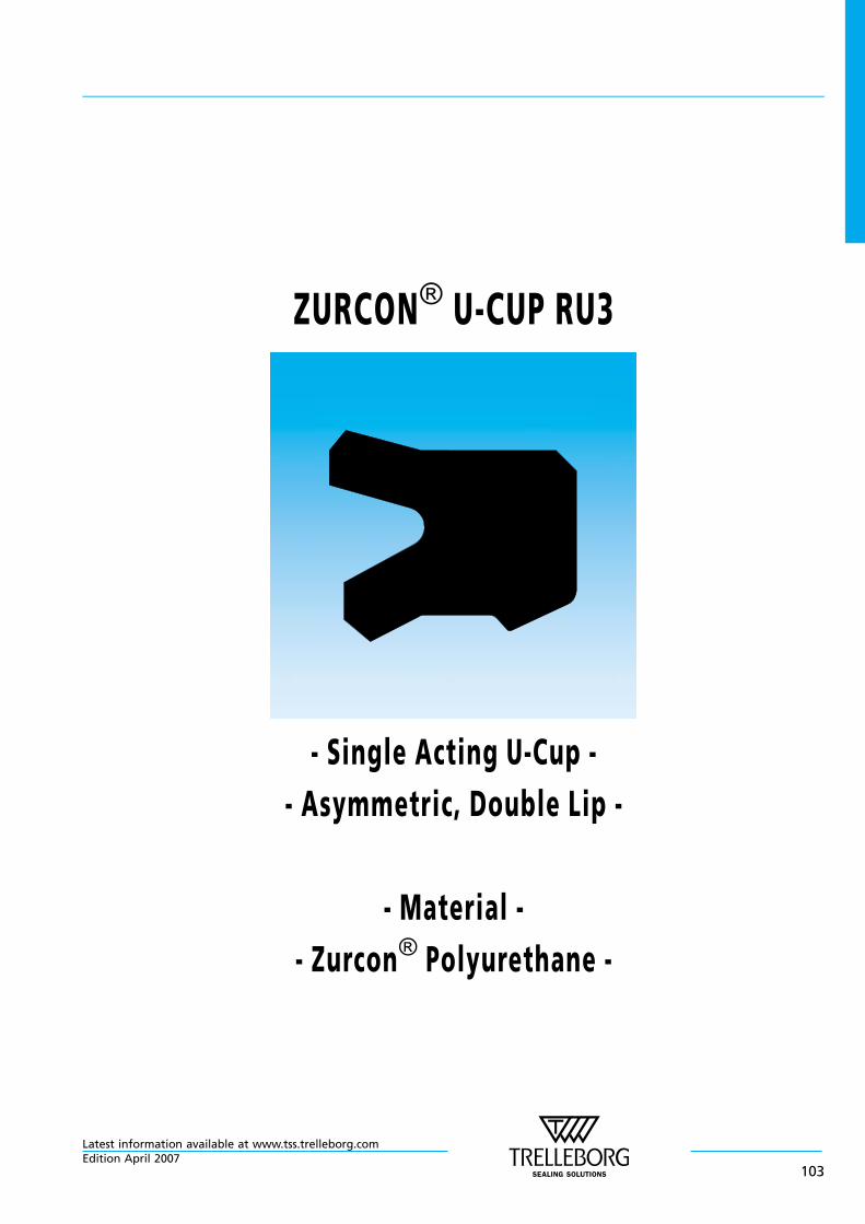
ZURCON® U-CUP RU3
- Single Acting U-Cup -
- Asymmetric, Double Lip -
- Material -
- Zurcon® Polyurethane -
Latest information available at www.tss.trelleborg.comEdition April 2007
103

Latest information available at www.tss.trelleborg.com
104Edition April 2007
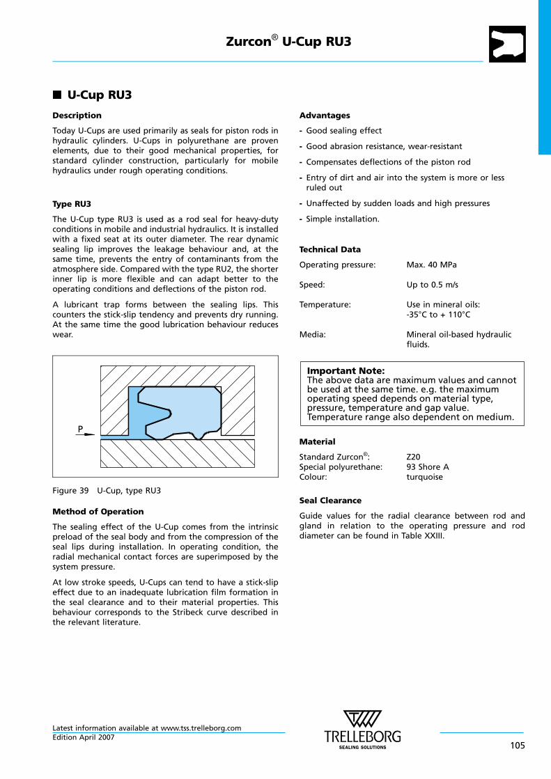
n U-Cup RU3
Description
Today U-Cups are used primarily as seals for piston rods inhydraulic cylinders. U-Cups in polyurethane are provenelements, due to their good mechanical properties, forstandard cylinder construction, particularly for mobilehydraulics under rough operating conditions.
Type RU3
The U-Cup type RU3 is used as a rod seal for heavy-dutyconditions in mobile and industrial hydraulics. It is installedwith a fixed seat at its outer diameter. The rear dynamicsealing lip improves the leakage behaviour and, at thesame time, prevents the entry of contaminants from theatmosphere side. Compared with the type RU2, the shorterinner lip is more flexible and can adapt better to theoperating conditions and deflections of the piston rod.
A lubricant trap forms between the sealing lips. Thiscounters the stick-slip tendency and prevents dry running.At the same time the good lubrication behaviour reduceswear.
P
Figure 39 U-Cup, type RU3
Method of Operation
The sealing effect of the U-Cup comes from the intrinsicpreload of the seal body and from the compression of theseal lips during installation. In operating condition, theradial mechanical contact forces are superimposed by thesystem pressure.
At low stroke speeds, U-Cups can tend to have a stick-slipeffect due to an inadequate lubrication film formation inthe seal clearance and to their material properties. Thisbehaviour corresponds to the Stribeck curve described inthe relevant literature.
Advantages
- Good sealing effect
- Good abrasion resistance, wear-resistant
- Compensates deflections of the piston rod
- Entry of dirt and air into the system is more or lessruled out
- Unaffected by sudden loads and high pressures
- Simple installation.
Technical Data
Operating pressure: Max. 40 MPa
Speed: Up to 0.5 m/s
Temperature: Use in mineral oils:-35°C to + 110°C
Media: Mineral oil-based hydraulicfluids.
Important Note:The above data are maximum values and cannotbe used at the same time. e.g. the maximumoperating speed depends on material type,pressure, temperature and gap value.Temperature range also dependent on medium.
Material
Standard Zurcon®: Z20Special polyurethane: 93 Shore AColour: turquoise
Seal Clearance
Guide values for the radial clearance between rod andgland in relation to the operating pressure and roddiameter can be found in Table XXIII.
Zurcon® U-Cup RU3
Latest information available at www.tss.trelleborg.comEdition April 2007
105

n Installation Recommendation
S
B
r max. 0.3
L
dN
D1
Figure 40 Installation drawingDimensions “S“ see Table XXIII
Ordering Example
U-Cup Type RU3Rod diameter: dN = 70.0 mmGroove diameter: D1 = 85.0 mmGroove width: L = 12.5 mmTSS Part No.: RU3000700 -
Material
Standard Zurcon®: Z20Special polyurethane: 93 Shore AColour: turquoise
Material code
TSS Series No.
TSS Article No. Z20
Rod diameter x 10
RU30
Quality Index (Standard)
-
Type (Standard)
0 0700
Table XXVI Installation dimensions / TSS Part No.
Note RodDiameter
GrooveDiameter
GrooveWidth
SealWidth
TSS Part No.
dN f8/h9 D1 H10 L +0.2 B
*
*
12.0
12.0
12.0
19.0
20.0
22.0
5.6
6.3
8.0
5.0
5.7
7.0
RU3100120
RU3200120
RU3000120
*
*
14.0
14.0
14.0
21.0
22.0
24.0
5.6
6.3
8.0
5.0
5.7
7.3
RU3100140
RU3200140
RU3000140
*
*
16.0
16.0
18.0
24.0
26.0
25.0
6.3
8.0
5.6
5.7
7.3
5.0
RU3200160
RU3000160
RU3200180
Dimensions printed in bold type correspond to ISO/DIN 5597 and ISO 5597/1. * Split grooveAdditional dimensions can be delivered on request.
Zurcon® U-Cup RU3
Latest information available at www.tss.trelleborg.com
106Edition April 2007

Note RodDiameter
GrooveDiameter
GrooveWidth
SealWidth
TSS Part No.
dN f8/h9 D1 H10 L +0.2 B
*
*
*
18.0
18.0
20.0
26.0
28.0
28.0
6.3
8.0
6.3
5.7
7.3
5.7
RU3300180
RU3000180
RU3300200
*
*
20.0
22.0
22.0
30.0
29.0
32.0
8.0
5.6
8.0
7.3
5.0
7.3
RU3000200
RU3100220
RU3000220
*
*
25.0
25.0
28.0
33.0
35.0
36.0
6.3
8.0
6.3
5.7
7.3
5.7
RU3100250
RU3000250
RU3400280
*
*
28.0
28.0
30.0
38.0
43.0
40.0
8.0
12.5
8.0
7.3
11.5
7.3
RU3100280
RU3300280
RU3000300
*
32.0
32.0
35.0
42.0
42.0
45.0
6.3
8.0
8.0
5.7
7.3
7.0
RU3200320
RU3000320
RU3000350
*
36.0
36.0
40.0
44.0
46.0
50.0
6.3
8.0
8.0
5.7
7.3
7.3
RU3100360
RU3000360
RU3100400
*
*
45.0
45.0
50.0
55.0
60.0
60.0
8.0
12.5
8.0
7.3
11.5
7.3
RU3000450
RU3100450
RU3000500
50.0
56.0
60.0
65.0
71.0
75.0
12.5
12.5
12.5
11.5
11.4
11.5
RU3200500
RU3000560
RU3300600
63.0
70.0
80.0
78.0
85.0
95.0
12.5
12.5
12.5
11.5
11.5
11.5
RU3000630
RU3000700
RU3000800
85.0
90.0
100.0
100.0
105.0
120.0
12.5
12.5
16.0
11.5
11.5
15.0
RU3000850
RU3000900
RU3101000
110.0
125.0
140.0
130.0
145.0
160.0
16.0
16.0
16.0
15.0
15.0
15.0
RU3001100
RU3001250
RU3001400
150.0
180.0
200.0
170.0
205.0
225.0
16.0
16.0
16.0
15.0
15.0
15.0
RU3001500
RU3001800
RU3002000
Dimensions printed in bold type correspond to ISO/DIN 5597 and ISO 5597/1. * Split grooveAdditional dimensions can be delivered on request.
Zurcon® U-Cup RU3
Latest information available at www.tss.trelleborg.comEdition April 2007
107
Zurcon® U-Cup RU3
Latest information available at www.tss.trelleborg.com
108Edition April 2007
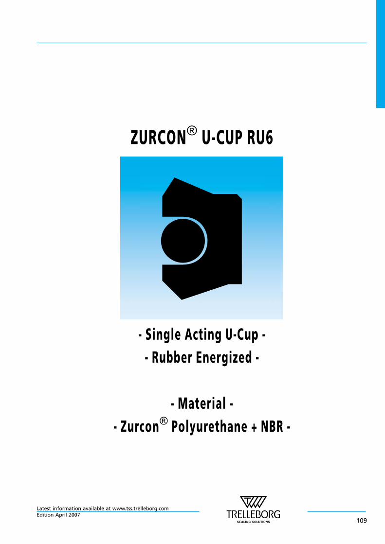
ZURCON® U-CUP RU6
- Single Acting U-Cup -
- Rubber Energized -
- Material -
- Zurcon® Polyurethane + NBR -
Latest information available at www.tss.trelleborg.comEdition April 2007
109

Latest information available at www.tss.trelleborg.com
110Edition April 2007
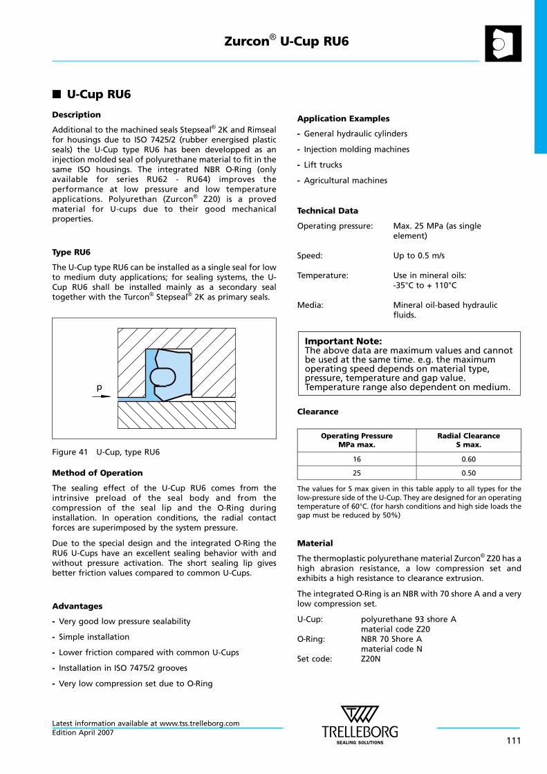
n U-Cup RU6
Description
Additional to the machined seals Stepseal® 2K and Rimsealfor housings due to ISO 7425/2 (rubber energised plasticseals) the U-Cup type RU6 has been developped as aninjection molded seal of polyurethane material to fit in thesame ISO housings. The integrated NBR O—Ring (onlyavailable for series RU62 - RU64) improves theperformance at low pressure and low temperatureapplications. Polyurethan (Zurcon® Z20) is a provedmaterial for U-cups due to their good mechanicalproperties.
Type RU6
The U-Cup type RU6 can be installed as a single seal for lowto medium duty applications; for sealing systems, the U-Cup RU6 shall be installed mainly as a secondary sealtogether with the Turcon® Stepseal® 2K as primary seals.
p
Figure 41 U-Cup, type RU6
Method of Operation
The sealing effect of the U-Cup RU6 comes from theintrinsive preload of the seal body and from thecompression of the seal lip and the O—Ring duringinstallation. In operation conditions, the radial contactforces are superimposed by the system pressure.
Due to the special design and the integrated O—Ring theRU6 U-Cups have an excellent sealing behavior with andwithout pressure activation. The short sealing lip givesbetter friction values compared to common U-Cups.
Advantages
- Very good low pressure sealability
- Simple installation
- Lower friction compared with common U-Cups
- Installation in ISO 7475/2 grooves
- Very low compression set due to O—Ring
Application Examples
- General hydraulic cylinders
- Injection molding machines
- Lift trucks
- Agricultural machines
Technical Data
Operating pressure: Max. 25 MPa (as singleelement)
Speed: Up to 0.5 m/s
Temperature: Use in mineral oils:-35°C to + 110°C
Media: Mineral oil-based hydraulicfluids.
Important Note:The above data are maximum values and cannotbe used at the same time. e.g. the maximumoperating speed depends on material type,pressure, temperature and gap value.Temperature range also dependent on medium.
Clearance
Operating PressureMPa max.
Radial ClearanceS max.
16 0.60
25 0.50
The values for S max given in this table apply to all types for thelow-pressure side of the U-Cup. They are designed for an operatingtemperature of 60°C. (for harsh conditions and high side loads thegap must be reduced by 50%)
Material
The thermoplastic polyurethane material Zurcon® Z20 has ahigh abrasion resistance, a low compression set andexhibits a high resistance to clearance extrusion.
The integrated O—Ring is an NBR with 70 shore A and a verylow compression set.
U-Cup: polyurethane 93 shore Amaterial code Z20
O—Ring: NBR 70 Shore Amaterial code N
Set code: Z20N
Zurcon® U-Cup RU6
Latest information available at www.tss.trelleborg.comEdition April 2007
111
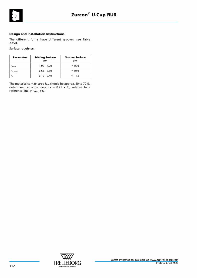
Design and Installation Instructions
The different forms have different grooves, see TableXXVII.
Surface roughness
Parameter Mating Surfaceµm
Groove Surfaceµm
Rmax 1.00 - 4.00 < 16.0
Rz DIN 0.63 - 2.50 < 10.0
Ra 0.10 - 0.40 < 1.6
The material contact area Rmr should be approx. 50 to 70%,determined at a cut depth c = 0.25 x Rz, relative to areference line of Cref. 5%.
Zurcon® U-Cup RU6
Latest information available at www.tss.trelleborg.com
112Edition April 2007
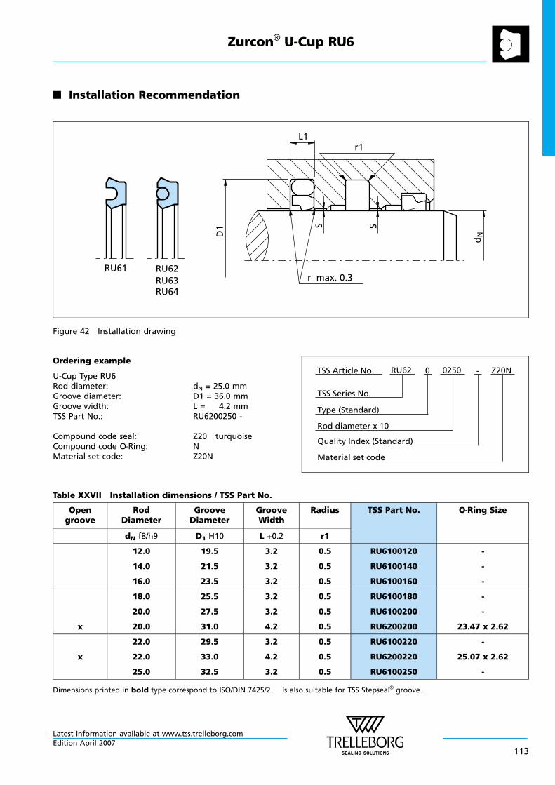
n Installation Recommendation
r max. 0.3
dND
1
r1L1
RU61 RU62RU63
SS
RU64
Figure 42 Installation drawing
Ordering example
U-Cup Type RU6Rod diameter: dN = 25.0 mmGroove diameter: D1 = 36.0 mmGroove width: L = 4.2 mmTSS Part No.: RU6200250 -
Compound code seal: Z20 turquoiseCompound code O—Ring: NMaterial set code: Z20N Material set code
TSS Series No.
TSS Article No. Z20N
Rod diameter x 10
RU62
Quality Index (Standard)
-
Type (Standard)
0 0250
Table XXVII Installation dimensions / TSS Part No.
Opengroove
RodDiameter
GrooveDiameter
GrooveWidth
Radius TSS Part No. O—Ring Size
dN f8/h9 D1 H10 L +0.2 r1
12.0
14.0
16.0
19.5
21.5
23.5
3.2
3.2
3.2
0.5
0.5
0.5
RU6100120
RU6100140
RU6100160
-
-
-
x
18.0
20.0
20.0
25.5
27.5
31.0
3.2
3.2
4.2
0.5
0.5
0.5
RU6100180
RU6100200
RU6200200
-
-
23.47 x 2.62
x
22.0
22.0
25.0
29.5
33.0
32.5
3.2
4.2
3.2
0.5
0.5
0.5
RU6100220
RU6200220
RU6100250
-
25.07 x 2.62
-
Dimensions printed in bold type correspond to ISO/DIN 7425/2. Is also suitable for TSS Stepseal® groove.
Zurcon® U-Cup RU6
Latest information available at www.tss.trelleborg.comEdition April 2007
113
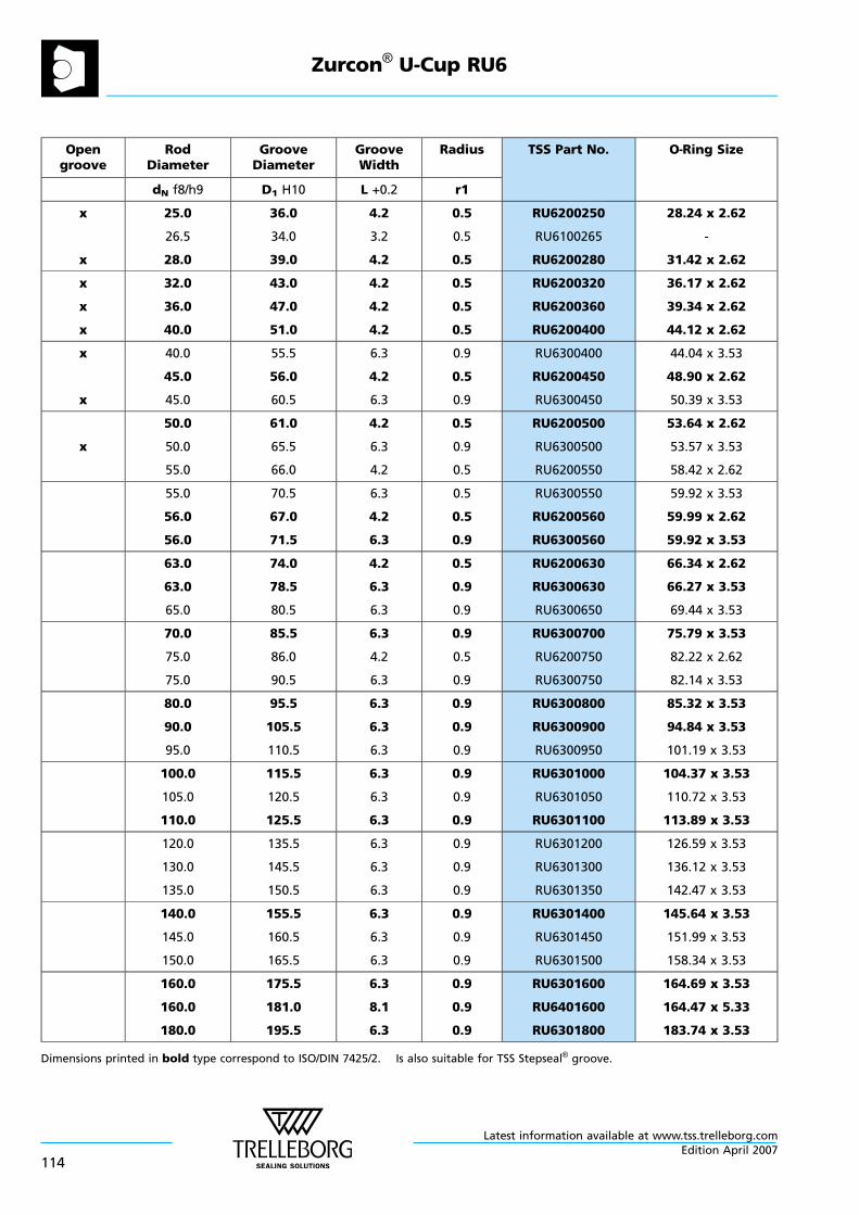
Opengroove
RodDiameter
GrooveDiameter
GrooveWidth
Radius TSS Part No. O—Ring Size
dN f8/h9 D1 H10 L +0.2 r1
x
x
25.0
26.5
28.0
36.0
34.0
39.0
4.2
3.2
4.2
0.5
0.5
0.5
RU6200250
RU6100265
RU6200280
28.24 x 2.62
-
31.42 x 2.62
x
x
x
32.0
36.0
40.0
43.0
47.0
51.0
4.2
4.2
4.2
0.5
0.5
0.5
RU6200320
RU6200360
RU6200400
36.17 x 2.62
39.34 x 2.62
44.12 x 2.62
x
x
40.0
45.0
45.0
55.5
56.0
60.5
6.3
4.2
6.3
0.9
0.5
0.9
RU6300400
RU6200450
RU6300450
44.04 x 3.53
48.90 x 2.62
50.39 x 3.53
x
50.0
50.0
55.0
61.0
65.5
66.0
4.2
6.3
4.2
0.5
0.9
0.5
RU6200500
RU6300500
RU6200550
53.64 x 2.62
53.57 x 3.53
58.42 x 2.62
55.0
56.0
56.0
70.5
67.0
71.5
6.3
4.2
6.3
0.5
0.5
0.9
RU6300550
RU6200560
RU6300560
59.92 x 3.53
59.99 x 2.62
59.92 x 3.53
63.0
63.0
65.0
74.0
78.5
80.5
4.2
6.3
6.3
0.5
0.9
0.9
RU6200630
RU6300630
RU6300650
66.34 x 2.62
66.27 x 3.53
69.44 x 3.53
70.0
75.0
75.0
85.5
86.0
90.5
6.3
4.2
6.3
0.9
0.5
0.9
RU6300700
RU6200750
RU6300750
75.79 x 3.53
82.22 x 2.62
82.14 x 3.53
80.0
90.0
95.0
95.5
105.5
110.5
6.3
6.3
6.3
0.9
0.9
0.9
RU6300800
RU6300900
RU6300950
85.32 x 3.53
94.84 x 3.53
101.19 x 3.53
100.0
105.0
110.0
115.5
120.5
125.5
6.3
6.3
6.3
0.9
0.9
0.9
RU6301000
RU6301050
RU6301100
104.37 x 3.53
110.72 x 3.53
113.89 x 3.53
120.0
130.0
135.0
135.5
145.5
150.5
6.3
6.3
6.3
0.9
0.9
0.9
RU6301200
RU6301300
RU6301350
126.59 x 3.53
136.12 x 3.53
142.47 x 3.53
140.0
145.0
150.0
155.5
160.5
165.5
6.3
6.3
6.3
0.9
0.9
0.9
RU6301400
RU6301450
RU6301500
145.64 x 3.53
151.99 x 3.53
158.34 x 3.53
160.0
160.0
180.0
175.5
181.0
195.5
6.3
8.1
6.3
0.9
0.9
0.9
RU6301600
RU6401600
RU6301800
164.69 x 3.53
164.47 x 5.33
183.74 x 3.53
Dimensions printed in bold type correspond to ISO/DIN 7425/2. Is also suitable for TSS Stepseal® groove.
Zurcon® U-Cup RU6
Latest information available at www.tss.trelleborg.com
114Edition April 2007
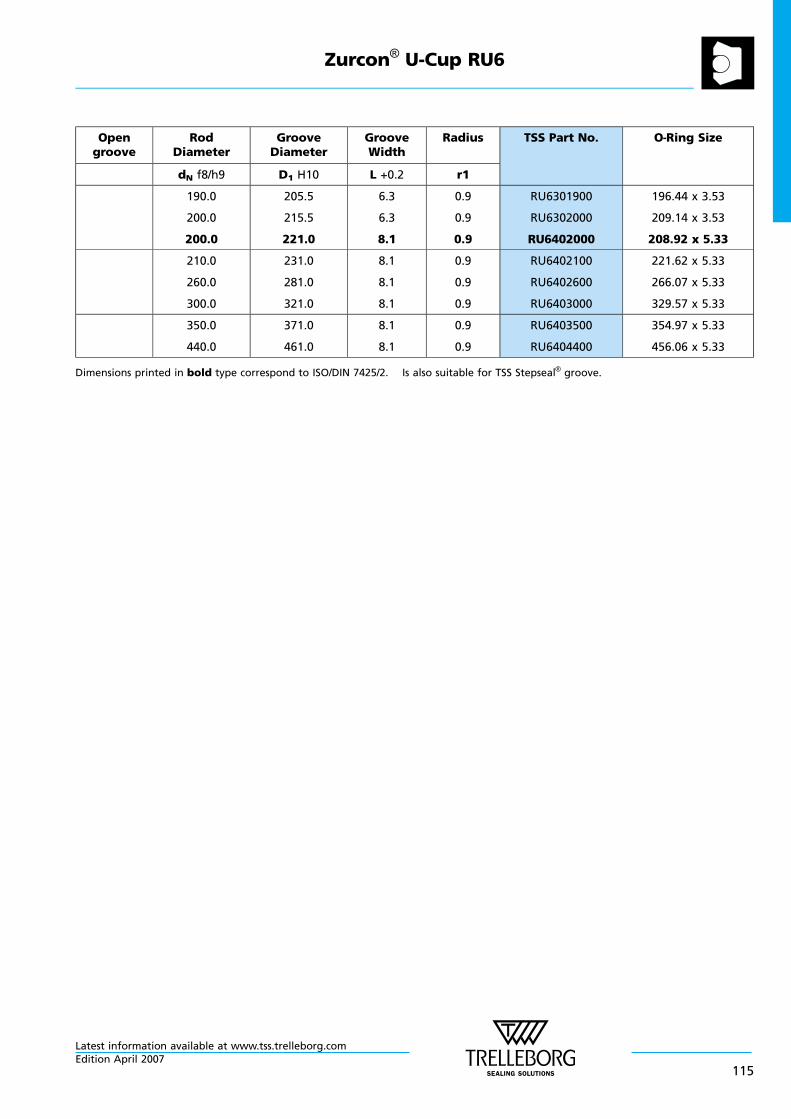
Opengroove
RodDiameter
GrooveDiameter
GrooveWidth
Radius TSS Part No. O—Ring Size
dN f8/h9 D1 H10 L +0.2 r1
190.0
200.0
200.0
205.5
215.5
221.0
6.3
6.3
8.1
0.9
0.9
0.9
RU6301900
RU6302000
RU6402000
196.44 x 3.53
209.14 x 3.53
208.92 x 5.33
210.0
260.0
300.0
231.0
281.0
321.0
8.1
8.1
8.1
0.9
0.9
0.9
RU6402100
RU6402600
RU6403000
221.62 x 5.33
266.07 x 5.33
329.57 x 5.33
350.0
440.0
371.0
461.0
8.1
8.1
0.9
0.9
RU6403500
RU6404400
354.97 x 5.33
456.06 x 5.33
Dimensions printed in bold type correspond to ISO/DIN 7425/2. Is also suitable for TSS Stepseal® groove.
Zurcon® U-Cup RU6
Latest information available at www.tss.trelleborg.comEdition April 2007
115
Zurcon® U-Cup RU6
Latest information available at www.tss.trelleborg.com
116Edition April 2007
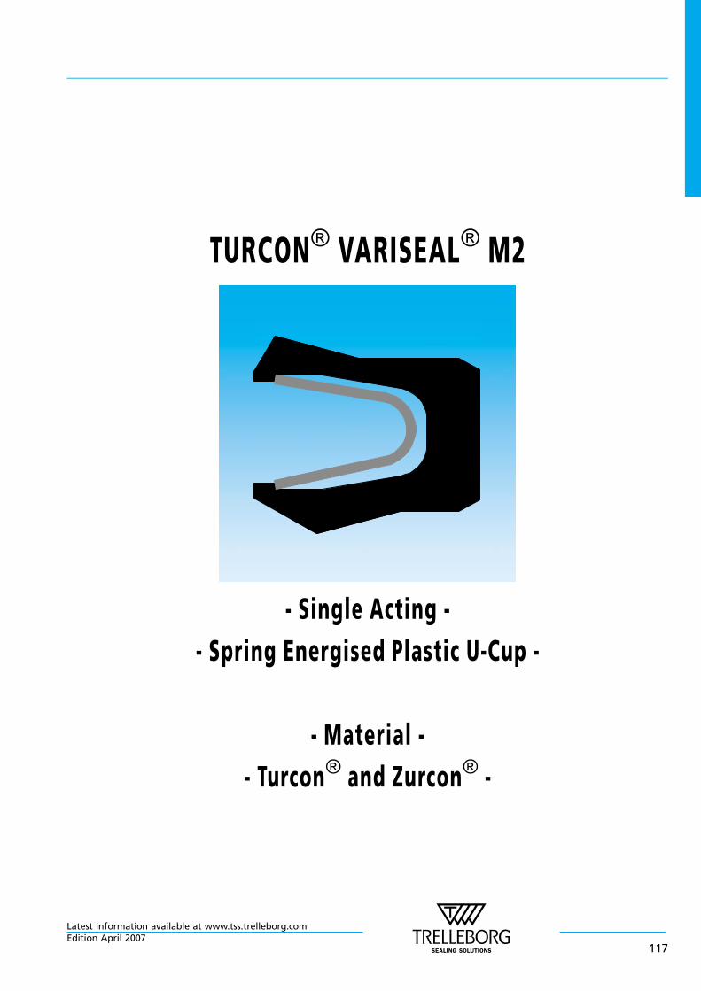
TURCON® VARISEAL® M2
- Single Acting -
- Spring Energised Plastic U-Cup -
- Material -
- Turcon® and Zurcon® -
Latest information available at www.tss.trelleborg.comEdition April 2007
117

Latest information available at www.tss.trelleborg.com
118Edition April 2007
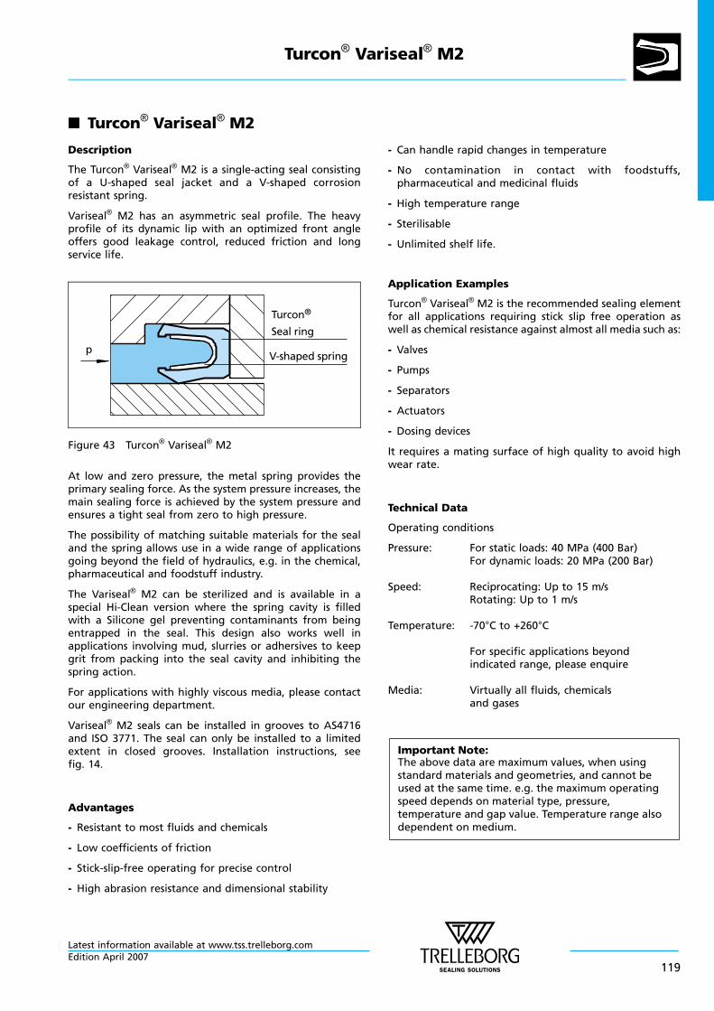
n Turcon® Variseal® M2
Description
The Turcon® Variseal® M2 is a single-acting seal consistingof a U-shaped seal jacket and a V-shaped corrosionresistant spring.
Variseal® M2 has an asymmetric seal profile. The heavyprofile of its dynamic lip with an optimized front angleoffers good leakage control, reduced friction and longservice life.
pV-shaped spring
Turcon®
Seal ring
Figure 43 Turcon® Variseal® M2
At low and zero pressure, the metal spring provides theprimary sealing force. As the system pressure increases, themain sealing force is achieved by the system pressure andensures a tight seal from zero to high pressure.
The possibility of matching suitable materials for the sealand the spring allows use in a wide range of applicationsgoing beyond the field of hydraulics, e.g. in the chemical,pharmaceutical and foodstuff industry.
The Variseal® M2 can be sterilized and is available in aspecial Hi-Clean version where the spring cavity is filledwith a Silicone gel preventing contaminants from beingentrapped in the seal. This design also works well inapplications involving mud, slurries or adhersives to keepgrit from packing into the seal cavity and inhibiting thespring action.
For applications with highly viscous media, please contactour engineering department.
Variseal® M2 seals can be installed in grooves to AS4716and ISO 3771. The seal can only be installed to a limitedextent in closed grooves. Installation instructions, seefig. 14.
Advantages
- Resistant to most fluids and chemicals
- Low coefficients of friction
- Stick-slip-free operating for precise control
- High abrasion resistance and dimensional stability
- Can handle rapid changes in temperature
- No contamination in contact with foodstuffs,pharmaceutical and medicinal fluids
- High temperature range
- Sterilisable
- Unlimited shelf life.
Application Examples
Turcon® Variseal® M2 is the recommended sealing elementfor all applications requiring stick slip free operation aswell as chemical resistance against almost all media such as:
- Valves
- Pumps
- Separators
- Actuators
- Dosing devices
It requires a mating surface of high quality to avoid highwear rate.
Technical Data
Operating conditions
Pressure: For static loads: 40 MPa (400 Bar)For dynamic loads: 20 MPa (200 Bar)
Speed: Reciprocating: Up to 15 m/sRotating: Up to 1 m/s
Temperature: -70°C to +260°C
For specific applications beyondindicated range, please enquire
Media: Virtually all fluids, chemicalsand gases
Important Note:The above data are maximum values, when usingstandard materials and geometries, and cannot beused at the same time. e.g. the maximum operatingspeed depends on material type, pressure,temperature and gap value. Temperature range alsodependent on medium.
Turcon® Variseal® M2
Latest information available at www.tss.trelleborg.comEdition April 2007
119
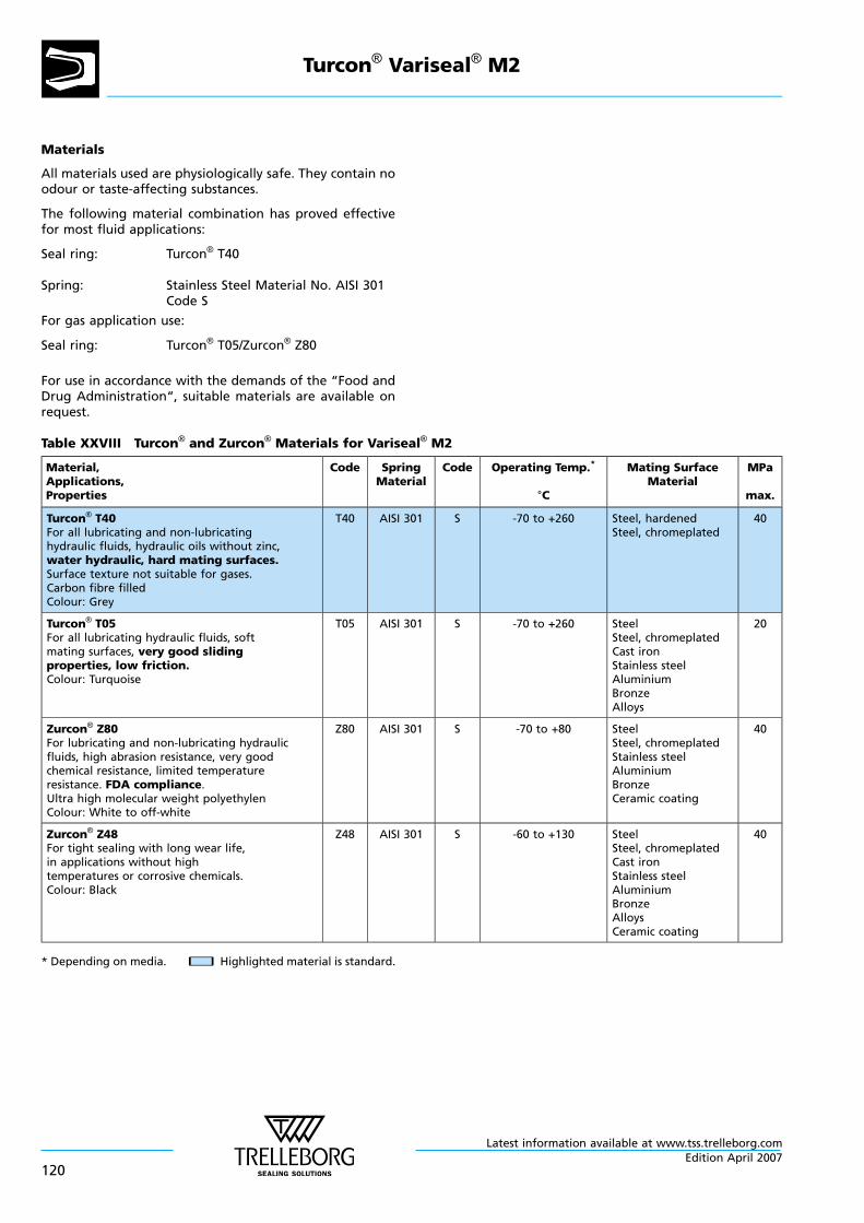
Materials
All materials used are physiologically safe. They contain noodour or taste-affecting substances.
The following material combination has proved effectivefor most fluid applications:
Seal ring: Turcon® T40
Spring: Stainless Steel Material No. AISI 301Code S
For gas application use:
Seal ring: Turcon® T05/Zurcon® Z80
For use in accordance with the demands of the “Food andDrug Administration“, suitable materials are available onrequest.
Table XXVIII Turcon® and Zurcon® Materials for Variseal® M2
Material,Applications,Properties
Code SpringMaterial
Code Operating Temp.*
°C
Mating SurfaceMaterial
MPa
max.
Turcon® T40For all lubricating and non-lubricatinghydraulic fluids, hydraulic oils without zinc,water hydraulic, hard mating surfaces.Surface texture not suitable for gases.Carbon fibre filledColour: Grey
T40 AISI 301 S -70 to +260 Steel, hardenedSteel, chromeplated
40
Turcon® T05For all lubricating hydraulic fluids, softmating surfaces, very good slidingproperties, low friction.Colour: Turquoise
T05 AISI 301 S -70 to +260 SteelSteel, chromeplatedCast ironStainless steelAluminiumBronzeAlloys
20
Zurcon® Z80For lubricating and non-lubricating hydraulicfluids, high abrasion resistance, very goodchemical resistance, limited temperatureresistance. FDA compliance.Ultra high molecular weight polyethylenColour: White to off-white
Z80 AISI 301 S -70 to +80 SteelSteel, chromeplatedStainless steelAluminiumBronzeCeramic coating
40
Zurcon® Z48For tight sealing with long wear life,in applications without hightemperatures or corrosive chemicals.Colour: Black
Z48 AISI 301 S -60 to +130 SteelSteel, chromeplatedCast ironStainless steelAluminiumBronzeAlloysCeramic coating
40
* Depending on media. nn Highlighted material is standard.
Turcon® Variseal® M2
Latest information available at www.tss.trelleborg.com
120Edition April 2007
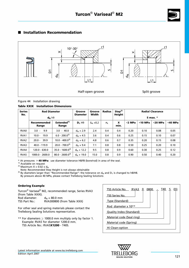
n Installation Recommendation
L1
r1D
1
dN
X
S
L1
r1
D1
dN
X
S
Split grooveHalf-open groove
10°-30°
Figure 44 Installation drawing
Table XXIX Installation Dimensions
SeriesNo.
Rod Diameter
dN h9
GrooveDiameter
GrooveWidth
Radius Step2)
HeightRadial Clearance
S max. *
RecommendedRange
Extended1)
RangeD1 H9 L1 +0.2 r1 X
min.<2 MPa <10 MPa <20 MPa <40 MPa
RVA0 3.0 - 9.9 3.0 - 40.0 dN + 2.9 2.4 0.4 0.4 0.20 0.10 0.08 0.05
RVA1 10.0 - 19.9 6.0 - 200.03) dN + 4.5 3.6 0.4 0.6 0.25 0.15 0.10 0.07
RVA2 20.0 - 39.9 10.0 - 400.03) dN + 6.2 4.8 0.6 0.7 0.35 0.20 0.15 0.08
RVA3 40.0 - 119.9 20.0 - 700.03) dN + 9.4 7.1 0.8 0.8 0.50 0.25 0.20 0.10
RVA4 120.0 - 630.0 35.0 - 1600.03) dN + 12.2 9.5 0.8 0.9 0.60 0.30 0.25 0.12
RVA5 1000.0 - 2600.0 80.0 - 2600.03) dN + 19.0 15.0 0.8 0.9 0.90 0.50 0.40 0.20
* At pressures > 40 MPa: use diameter tolerance H8/f8 (bore/rod) in area of the seal.1) Available on request2) Maximum X = 0.02 x dNNote: Recommended Step Height is not always obtainable
3) By diameters larger than “Recommended Range“: the tolerance on dN and D1 is changed to h8/H8.By pressure above 40 MPa, please contact Trelleborg Sealing Solutions
Ordering Example
Turcon® Variseal® M2, recommended range, Series RVA3(from Table XXIX).Rod diameter: dN = 80.0 mmTSS Part No.: RVA300800 (from Table XXX)
For other seal and spring materials please contact theTrelleborg Sealing Solutions representative.
** For diameters 1000.0 mm multiply only by factor 1.Example: RVA5 for diameter 1200.0 mm.TSS Article No.: RVA5X1200 - T40S.
Material code (Seal ring)
TSS Series No.
TSS Article No. T400800 S
Material code (Spring)
Hi Clean-option
Rod diameter x 10**
RVA3
Quality Index (Standard)
-
Type (Standard)
(D)0
Turcon® Variseal® M2
Latest information available at www.tss.trelleborg.comEdition April 2007
121
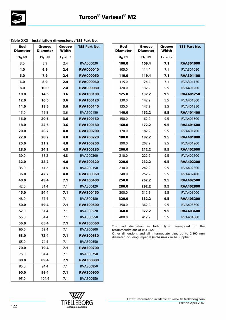
Table XXX Installation dimensions / TSS Part No.
RodDiameter
GrooveDiameter
GrooveWidth
TSS Part No.
dN h9 D1 H9 L1 +0.2
3.0
4.0
5.0
5.9
6.9
7.9
2.4
2.4
2.4
RVA000030
RVA000040
RVA000050
6.0
8.0
10.0
8.9
10.9
14.5
2.4
2.4
3.6
RVA000060
RVA000080
RVA100100
12.0
14.0
15.0
16.5
18.5
19.5
3.6
3.6
3.6
RVA100120
RVA100140
RVA100150
16.0
18.0
20.0
20.5
22.5
26.2
3.6
3.6
4.8
RVA100160
RVA100180
RVA200200
22.0
25.0
28.0
28.2
31.2
34.2
4.8
4.8
4.8
RVA200220
RVA200250
RVA200280
30.0
32.0
35.0
36.2
38.2
41.2
4.8
4.8
4.8
RVA200300
RVA200320
RVA200350
36.0
40.0
42.0
42.2
49.4
51.4
4.8
7.1
7.1
RVA200360
RVA300400
RVA300420
45.0
48.0
50.0
54.4
57.4
59.4
7.1
7.1
7.1
RVA300450
RVA300480
RVA300500
52.0
55.0
56.0
61.4
64.4
65.4
7.1
7.1
7.1
RVA300520
RVA300550
RVA300560
60.0
63.0
65.0
69.4
72.4
74.4
7.1
7.1
7.1
RVA300600
RVA300630
RVA300650
70.0
75.0
80.0
79.4
84.4
89.4
7.1
7.1
7.1
RVA300700
RVA300750
RVA300800
85.0
90.0
95.0
94.4
99.4
104.4
7.1
7.1
7.1
RVA300850
RVA300900
RVA300950
RodDiameter
GrooveDiameter
GrooveWidth
TSS Part No.
dN h9 D1 H9 L1 +0.2
100.0
105.0
110.0
109.4
114.4
119.4
7.1
7.1
7.1
RVA301000
RVA301050
RVA301100
115.0
120.0
125.0
124.4
132.2
137.2
7.1
9.5
9.5
RVA301150
RVA401200
RVA401250
130.0
135.0
140.0
142.2
147.2
152.2
9.5
9.5
9.5
RVA401300
RVA401350
RVA401400
150.0
160.0
170.0
162.2
172.2
182.2
9.5
9.5
9.5
RVA401500
RVA401600
RVA401700
180.0
190.0
200.0
192.2
202.2
212.2
9.5
9.5
9.5
RVA401800
RVA401900
RVA402000
210.0
220.0
230.0
222.2
232.2
242.2
9.5
9.5
9.5
RVA402100
RVA402200
RVA402300
240.0
250.0
280.0
252.2
262.2
292.2
9.5
9.5
9.5
RVA402400
RVA402500
RVA402800
300.0
320.0
350.0
312.2
332.2
362.2
9.5
9.5
9.5
RVA403000
RVA403200
RVA403500
360.0
400.0
372.2
412.2
9.5
9.5
RVA403600
RVA404000
The rod diameters in bold type correspond to therecommendations of ISO 3320.Other dimensions and all intermediate sizes up to 2.500 mmdiameter including imperial (inch) sizes can be supplied.
Turcon® Variseal® M2
Latest information available at www.tss.trelleborg.com
122Edition April 2007
TURCON® GLYD RING®
- Double Acting -
- Rubber Energised Plastic Faced Seal -
- Material -
- Turcon® and Zurcon® -
Latest information available at www.tss.trelleborg.comEdition April 2007
123

Latest information available at www.tss.trelleborg.com
124Edition April 2007
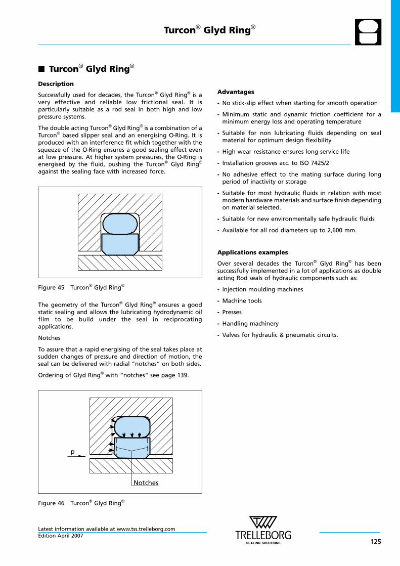
n Turcon® Glyd Ring®
Description
Successfully used for decades, the Turcon® Glyd Ring® is avery effective and reliable low frictional seal. It isparticularly suitable as a rod seal in both high and lowpressure systems.
The double acting Turcon® Glyd Ring® is a combination of aTurcon® based slipper seal and an energising O—Ring. It isproduced with an interference fit which together with thesqueeze of the O—Ring ensures a good sealing effect evenat low pressure. At higher system pressures, the O—Ring isenergised by the fluid, pushing the Turcon® Glyd Ring®
against the sealing face with increased force.
Figure 45 Turcon® Glyd Ring®
The geometry of the Turcon® Glyd Ring® ensures a goodstatic sealing and allows the lubricating hydrodynamic oilfilm to be build under the seal in reciprocatingapplications.
Notches
To assure that a rapid energising of the seal takes place atsudden changes of pressure and direction of motion, theseal can be delivered with radial “notches“ on both sides.
Ordering of Glyd Ring® with “notches“ see page 139.
Notches
p
Figure 46 Turcon® Glyd Ring®
Advantages
- No stick-slip effect when starting for smooth operation
- Minimum static and dynamic friction coefficient for aminimum energy loss and operating temperature
- Suitable for non lubricating fluids depending on sealmaterial for optimum design flexibility
- High wear resistance ensures long service life
- Installation grooves acc. to ISO 7425/2
- No adhesive effect to the mating surface during longperiod of inactivity or storage
- Suitable for most hydraulic fluids in relation with mostmodern hardware materials and surface finish dependingon material selected.
- Suitable for new environmentally safe hydraulic fluids
- Available for all rod diameters up to 2,600 mm.
Applications examples
Over several decades the Turcon® Glyd Ring® has beensuccessfully implemented in a lot of applications as doubleacting Rod seals of hydraulic components such as:
- Injection moulding machines
- Machine tools
- Presses
- Handling machinery
- Valves for hydraulic & pneumatic circuits.
Turcon® Glyd Ring®
Latest information available at www.tss.trelleborg.comEdition April 2007
125
Technical Data
Operating conditions:
The Turcon® Glyd Ring® is recommended for reciprocating(with a length of stroke at least twice the groove width)and helical movements.
Pressure: up to 80MPa
Speed: up to 15m/s
Frequency: up to 5 Hz.
Temperature: -45°C to +200°C(depending on O—Ring Material)
Media: Mineral oil based hydraulic fluids,barely flammable hydraulic fluids,environmentally safe hydraulic fluids(biological degradable oils), water,air and others. Depending on theO—Ring material compatibility.
Clearance: the maximum permissible radialclearance Smax is shown in the tableXXXII, as a function of the operatingpressure and functional diameter.
Important Note:The above data are maximum values and cannotbe used at the same time. e.g. the maximumoperating speed depends on material type,pressure, temperature and gap value.Temperature range also dependent on medium.
Materials
Standard Application:
For hydraulic components with reciprocating movement inmineral oils or medium with good lubricating performance.
Turcon® seal: Turcon® T46
Energiser: O—Ring NBR 70 shore A or FKM 70Shore A depending on thetemperature
Set code: T46N or T46V
Special Application:
Short stroke movements, non-lubricating fluids orpneumatic applications require self-lubricating sealingmaterials. Therefore we recommend:
Turcon® Seal: Turcon® T29
Energiser: O—Ring NBR 70 Shore A or FKM 70Shore A depending on thetemperature
Set code: T29N or T29V
If low friction coefficient is required, we recommend:
Turcon® Seal: Turcon® T05
Energiser: O—Ring NBR 70 Shore A orFKM 70 Shore A depending on thetemperature.For special requirementsother elastomers are available onrequest
Set code: T05N or T05V
If rougher surface finish must be sealed, we recommend:
Zurcon® seal: Zurcon® Z51
Energiser: O—Ring NBR 70 Shore A
Set code: Z51N
Turcon® Glyd Ring®
Latest information available at www.tss.trelleborg.com
126Edition April 2007
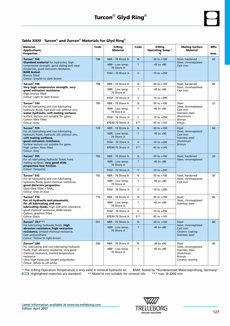
Table XXXI Turcon® and Zurcon® Materials for Glyd Ring®
Material,Applications,Properties
Code O—RingMaterial
Code O—RingOperating Temp.*
°C
Mating SurfaceMaterial
MPa
max.
Turcon® T46Standard material for hydraulics, highcompressive strength, good sliding and wearproperties, good extrusion resistance,BAM tested.Bronze filledColour: Greyish to dark brown
T46 NBR - 70 Shore A N -30 to +100 Steel, hardenedSteel, chromeplatedCast iron
60
NBR - Low temp.70 Shore A
T -45 to +80
FKM - 70 Shore A V -10 to +200
Turcon® T08Very high compressive strength, verygood extrusion resistance.High bronze filledColour: Light to dark brown
T08 NBR - 70 Shore A N -30 to +100 Steel, hardenedSteel, chromeplatedCast iron
80
NBR - Low temp.70 Shore A
T -45 to +80
FKM - 70 Shore A V -10 to +200
Turcon® T40For all lubricating and non-lubricatinghydraulic fluids, hydraulic oils without zinc,water hydraulic, soft mating surfaces.Surface texture not suitable for gases.Carbon fibre filledColour: Grey
T40 NBR - 70 Shore A N -30 to +100 SteelSteel, chromeplatedCast ironStainless steelAluminiumBronzeAlloys
25
NBR - Low temp.70 Shore A
T -45 to +80
FKM - 70 Shore A V -10 to +200
EPDM-70 Shore A E** -45 to +145
Turcon® T29For all lubricating and non-lubricatinghydraulic fluids, hydraulic oils without zinc,soft mating surfaces,good extrusion resistance.Surface texture not suitable for gases.High carbon fibre filledColour: Grey
T29 NBR - 70 Shore A N -30 to +100 SteelSteel, chromeplatedCast ironStainless steelAluminiumBronze
60
NBR - Low temp.70 Shore A
T -45 to +80
FKM - 70 Shore A V -10 to +200
EPDM-70 Shore A E** -45 to +145
Turcon® T05For all lubricating hydraulic fluids, hardmating surfaces, very good slideproperties, low friction.Colour: Turquoise
T05 NBR - 70 Shore A N -30 to +100 Steel, hardenedSteel, chromeplated
20
NBR - Low temp.70 Shore A
T -45 to +80
FKM - 70 Shore A V -10 to +200
Turcon® T42For all lubricating and non-lubricatinghydraulic fluids, good chemical resistance,good dielectric properties.Glass fibre filled + MoS2Colour: Grey to blue
T42 NBR - 70 Shore A N -30 to +100 Steel, hardenedSteel, chromeplatedCast iron
30
NBR - Low temp.70 Shore A
T -45 to +80
FKM - 70 Shore A V -10 to +200
Turcon® T10For oil hydraulic and pneumatic,for all lubricating and non-lubricating fluids, high extrusion resistance,good chemical resistance, BAM tested.Carbon, graphite filledColour: Black
T10 NBR - 70 Shore A N -30 to +100 SteelSteel, chromeplatedStainless steel
60
NBR - Low temp.70 Shore A
T -45 to +80
FKM - 70 Shore A V -10 to +200
EPDM-70 Shore A E** -45 to +145
Zurcon® Z51***For lubricating hydraulic fluids, highabrasion resistance, high extrusionresistance, limited chemical resistance.Cast polyurethaneColour: Yellow to light-brown
Z51 NBR - 70 Shore A N -30 to +100 SteelSteel, chromeplatedCast ironCeramic coatingStainless steel
80
NBR - Low temp.70 Shore A
T -45 to +80
Zurcon® Z80For lubricating and non-lubricating hydraulicfluids, high abrasion resistance, very goodchemical resistance, limited temperatureresistance.Ultra high molecular weight polyethylenColour: White to off-white
Z80 NBR - 70 Shore A N -30 to +80 SteelSteel, chromeplatedStainless steelAluminiumBronzeCeramic coating
40
NBR - Low temp.70 Shore A
T -45 to +80
* The O—Ring Operation Temperature is only valid in mineral hydraulic oil. BAM: Tested by “Bundesanstalt Materialprufung, Germany“.nn Highlighted materials are standard. ** Material not suitable for mineral oils. *** max. Ø 2200 mm
Turcon® Glyd Ring®
Latest information available at www.tss.trelleborg.comEdition April 2007
127
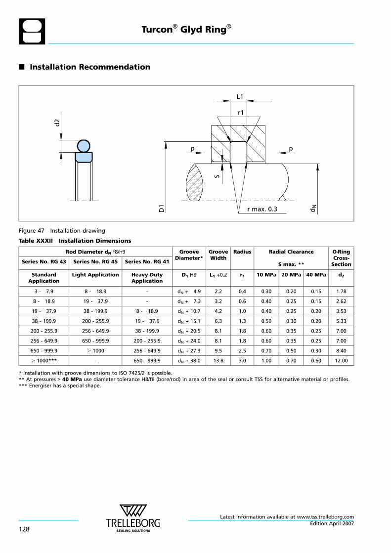
n Installation Recommendation
d2
L1
r1
p
r max. 0.3
p
D1
S
dN
Figure 47 Installation drawing
Table XXXII Installation Dimensions
Rod Diameter dN f8/h9 GrooveDiameter*
GrooveWidth
Radius Radial Clearance
S max. **
O—RingCross-Section
Series No. RG 43 Series No. RG 45 Series No. RG 41
StandardApplication
Light Application Heavy DutyApplication
D1 H9 L1 +0.2 r1 10 MPa 20 MPa 40 MPa d2
3 - 7.9 8 - 18.9 - dN + 4.9 2.2 0.4 0.30 0.20 0.15 1.78
8 - 18.9 19 - 37.9 - dN + 7.3 3.2 0.6 0.40 0.25 0.15 2.62
19 - 37.9 38 - 199.9 8 - 18.9 dN + 10.7 4.2 1.0 0.40 0.25 0.20 3.53
38 - 199.9 200 - 255.9 19 - 37.9 dN + 15.1 6.3 1.3 0.50 0.30 0.20 5.33
200 - 255.9 256 - 649.9 38 - 199.9 dN + 20.5 8.1 1.8 0.60 0.35 0.25 7.00
256 - 649.9 650 - 999.9 200 - 255.9 dN + 24.0 8.1 1.8 0.60 0.35 0.25 7.00
650 - 999.9 1000 256 - 649.9 dN + 27.3 9.5 2.5 0.70 0.50 0.30 8.40
1000*** - 650 - 999.9 dN + 38.0 13.8 3.0 1.00 0.70 0.60 12.00
* Installation with groove dimensions to ISO 7425/2 is possible.** At pressures > 40 MPa use diameter tolerance H8/f8 (bore/rod) in area of the seal or consult TSS for alternative material or profiles.*** Energiser has a special shape.
Turcon® Glyd Ring®
Latest information available at www.tss.trelleborg.com
128Edition April 2007
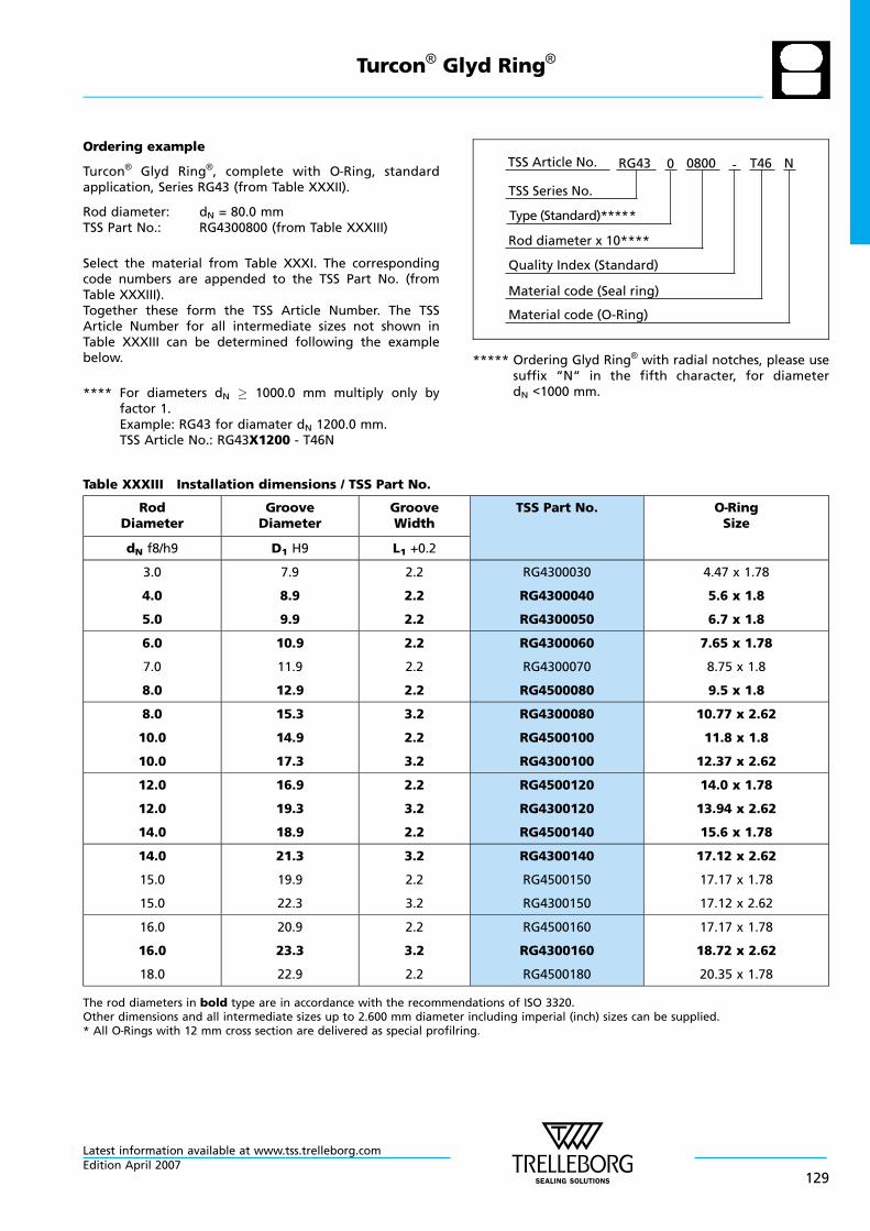
Ordering example
Turcon® Glyd Ring®, complete with O—Ring, standardapplication, Series RG43 (from Table XXXII).
Rod diameter: dN = 80.0 mmTSS Part No.: RG4300800 (from Table XXXIII)
Select the material from Table XXXI. The correspondingcode numbers are appended to the TSS Part No. (fromTable XXXIII).Together these form the TSS Article Number. The TSSArticle Number for all intermediate sizes not shown inTable XXXIII can be determined following the examplebelow.
**** For diameters dN 1000.0 mm multiply only byfactor 1.Example: RG43 for diamater dN 1200.0 mm.TSS Article No.: RG43X1200 - T46N
Material code (Seal ring)
TSS Series No.
TSS Article No. T460800 N
Material code (O-Ring)
Rod diameter x 10****
RG43
Quality Index (Standard)
-
Type (Standard)*****
0
***** Ordering Glyd Ring® with radial notches, please usesuffix “N“ in the fifth character, for diameterdN <1000 mm.
Table XXXIII Installation dimensions / TSS Part No.
RodDiameter
GrooveDiameter
GrooveWidth
TSS Part No. O—RingSize
dN f8/h9 D1 H9 L1 +0.2
3.0
4.0
5.0
7.9
8.9
9.9
2.2
2.2
2.2
RG4300030
RG4300040
RG4300050
4.47 x 1.78
5.6 x 1.8
6.7 x 1.8
6.0
7.0
8.0
10.9
11.9
12.9
2.2
2.2
2.2
RG4300060
RG4300070
RG4500080
7.65 x 1.78
8.75 x 1.8
9.5 x 1.8
8.0
10.0
10.0
15.3
14.9
17.3
3.2
2.2
3.2
RG4300080
RG4500100
RG4300100
10.77 x 2.62
11.8 x 1.8
12.37 x 2.62
12.0
12.0
14.0
16.9
19.3
18.9
2.2
3.2
2.2
RG4500120
RG4300120
RG4500140
14.0 x 1.78
13.94 x 2.62
15.6 x 1.78
14.0
15.0
15.0
21.3
19.9
22.3
3.2
2.2
3.2
RG4300140
RG4500150
RG4300150
17.12 x 2.62
17.17 x 1.78
17.12 x 2.62
16.0
16.0
18.0
20.9
23.3
22.9
2.2
3.2
2.2
RG4500160
RG4300160
RG4500180
17.17 x 1.78
18.72 x 2.62
20.35 x 1.78
The rod diameters in bold type are in accordance with the recommendations of ISO 3320.Other dimensions and all intermediate sizes up to 2.600 mm diameter including imperial (inch) sizes can be supplied.* All O—Rings with 12 mm cross section are delivered as special profilring.
Turcon® Glyd Ring®
Latest information available at www.tss.trelleborg.comEdition April 2007
129
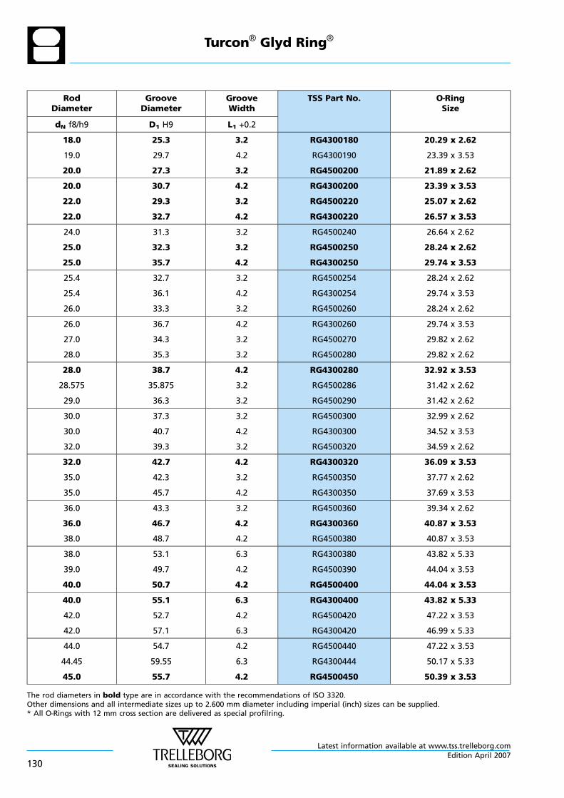
RodDiameter
GrooveDiameter
GrooveWidth
TSS Part No. O—RingSize
dN f8/h9 D1 H9 L1 +0.2
18.0
19.0
20.0
25.3
29.7
27.3
3.2
4.2
3.2
RG4300180
RG4300190
RG4500200
20.29 x 2.62
23.39 x 3.53
21.89 x 2.62
20.0
22.0
22.0
30.7
29.3
32.7
4.2
3.2
4.2
RG4300200
RG4500220
RG4300220
23.39 x 3.53
25.07 x 2.62
26.57 x 3.53
24.0
25.0
25.0
31.3
32.3
35.7
3.2
3.2
4.2
RG4500240
RG4500250
RG4300250
26.64 x 2.62
28.24 x 2.62
29.74 x 3.53
25.4
25.4
26.0
32.7
36.1
33.3
3.2
4.2
3.2
RG4500254
RG4300254
RG4500260
28.24 x 2.62
29.74 x 3.53
28.24 x 2.62
26.0
27.0
28.0
36.7
34.3
35.3
4.2
3.2
3.2
RG4300260
RG4500270
RG4500280
29.74 x 3.53
29.82 x 2.62
29.82 x 2.62
28.0
28.575
29.0
38.7
35.875
36.3
4.2
3.2
3.2
RG4300280
RG4500286
RG4500290
32.92 x 3.53
31.42 x 2.62
31.42 x 2.62
30.0
30.0
32.0
37.3
40.7
39.3
3.2
4.2
3.2
RG4500300
RG4300300
RG4500320
32.99 x 2.62
34.52 x 3.53
34.59 x 2.62
32.0
35.0
35.0
42.7
42.3
45.7
4.2
3.2
4.2
RG4300320
RG4500350
RG4300350
36.09 x 3.53
37.77 x 2.62
37.69 x 3.53
36.0
36.0
38.0
43.3
46.7
48.7
3.2
4.2
4.2
RG4500360
RG4300360
RG4500380
39.34 x 2.62
40.87 x 3.53
40.87 x 3.53
38.0
39.0
40.0
53.1
49.7
50.7
6.3
4.2
4.2
RG4300380
RG4500390
RG4500400
43.82 x 5.33
44.04 x 3.53
44.04 x 3.53
40.0
42.0
42.0
55.1
52.7
57.1
6.3
4.2
6.3
RG4300400
RG4500420
RG4300420
43.82 x 5.33
47.22 x 3.53
46.99 x 5.33
44.0
44.45
45.0
54.7
59.55
55.7
4.2
6.3
4.2
RG4500440
RG4300444
RG4500450
47.22 x 3.53
50.17 x 5.33
50.39 x 3.53
The rod diameters in bold type are in accordance with the recommendations of ISO 3320.Other dimensions and all intermediate sizes up to 2.600 mm diameter including imperial (inch) sizes can be supplied.* All O—Rings with 12 mm cross section are delivered as special profilring.
Turcon® Glyd Ring®
Latest information available at www.tss.trelleborg.com
130Edition April 2007

RodDiameter
GrooveDiameter
GrooveWidth
TSS Part No. O—RingSize
dN f8/h9 D1 H9 L1 +0.2
45.0
48.0
48.0
60.1
58.7
63.1
6.3
4.2
6.3
RG4300450
RG4500480
RG4300480
50.17 x 5.33
51.5 x 3.55
53.34 x 5.33
50.0
50.0
50.8
60.7
65.1
61.5
4.2
6.3
4.2
RG4500500
RG4300500
RG4500508
53.57 x 3.53
56.52 x 5.33
53.57 x 3.53
50.8
52.0
52.0
65.9
62.7
67.1
6.3
4.2
6.3
RG4300508
RG4500520
RG4300520
56.52 x 5.33
56.74 x 3.53
56.52 x 5.33
54.0
55.0
55.0
69.1
65.7
70.1
6.3
4.2
6.3
RG4300540
RG4500550
RG4300550
59.69 x 5.33
59.92 x 3.53
59.69 x 5.33
56.0
56.0
58.0
66.7
71.1
73.1
4.2
6.3
6.3
RG4500560
RG4300560
RG4300580
59.92 x 3.53
62.87 x 5.33
62.87 x 5.33
60.0
60.0
63.0
70.7
75.1
73.7
4.2
6.3
4.2
RG4500600
RG4300600
RG4500630
63.09 x 3.53
66.04 x 5.33
66.27 x 3.53
63.0
65.0
67.0
78.1
80.1
77.7
6.3
6.3
4.2
RG4300630
RG4300650
RG4500670
69.22 x 5.33
69.22 x 5.33
72.62 x 3.53
70.0
70.0
72.0
80.7
85.1
82.7
4.2
6.3
4.2
RG4500700
RG4300700
RG4500720
75.79 x 3.53
75.57 x 5.33
75.79 x 3.53
75.0
75.0
80.0
85.7
90.1
90.7
4.2
6.3
4.2
RG4500750
RG4300750
RG4500800
78.97 x 3.53
81.92 x 5.33
85.32 x 3.53
80.0
83.0
85.0
95.1
93.7
100.1
6.3
4.2
6.3
RG4300800
RG4500830
RG4300850
85.09 x 5.33
88.49 x 3.53
91.44 x 5.33
86.0
90.0
90.0
96.7
100.7
105.1
4.2
4.2
6.3
RG4500860
RG4500900
RG4300900
91.67 x 3.53
94.84 x 3.53
94.62 x 5.33
92.0
95.0
95.0
102.7
105.7
110.1
4.2
4.2
6.3
RG4500920
RG4500950
RG4300950
98.02 x 3.53
101.19 x 3.53
100.97 x 5.33
The rod diameters in bold type are in accordance with the recommendations of ISO 3320.Other dimensions and all intermediate sizes up to 2.600 mm diameter including imperial (inch) sizes can be supplied.* All O—Rings with 12 mm cross section are delivered as special profilring.
Turcon® Glyd Ring®
Latest information available at www.tss.trelleborg.comEdition April 2007
131
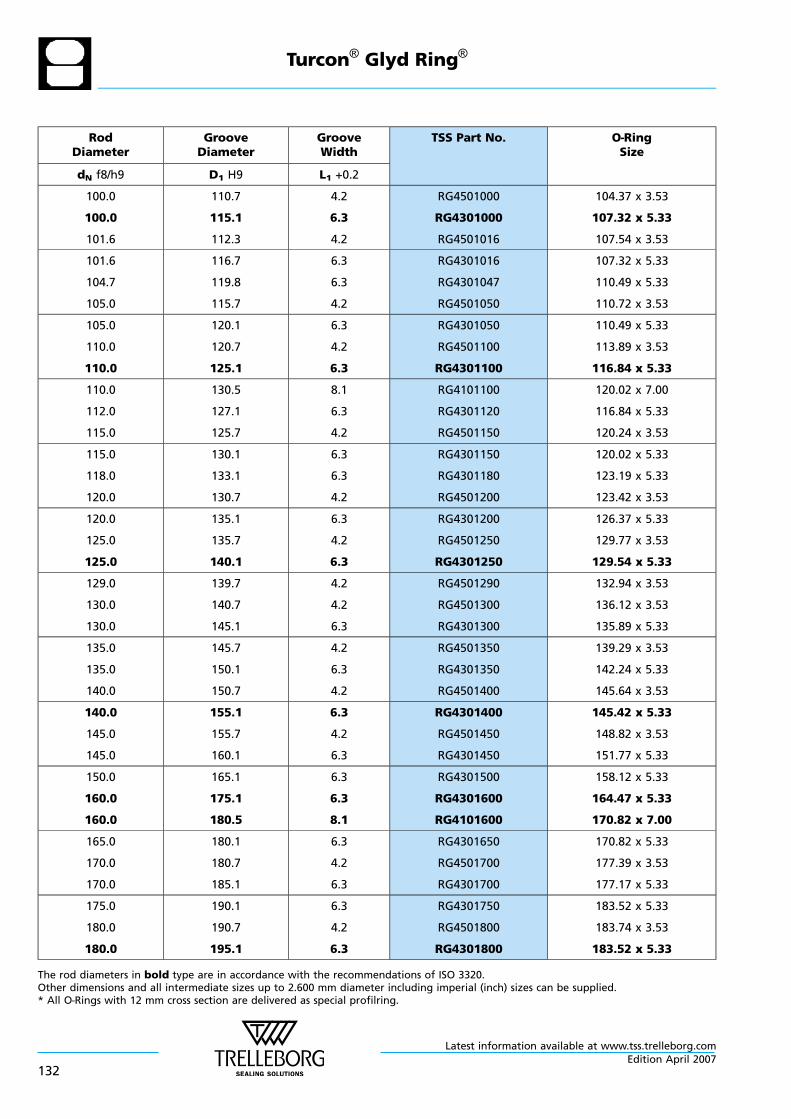
RodDiameter
GrooveDiameter
GrooveWidth
TSS Part No. O—RingSize
dN f8/h9 D1 H9 L1 +0.2
100.0
100.0
101.6
110.7
115.1
112.3
4.2
6.3
4.2
RG4501000
RG4301000
RG4501016
104.37 x 3.53
107.32 x 5.33
107.54 x 3.53
101.6
104.7
105.0
116.7
119.8
115.7
6.3
6.3
4.2
RG4301016
RG4301047
RG4501050
107.32 x 5.33
110.49 x 5.33
110.72 x 3.53
105.0
110.0
110.0
120.1
120.7
125.1
6.3
4.2
6.3
RG4301050
RG4501100
RG4301100
110.49 x 5.33
113.89 x 3.53
116.84 x 5.33
110.0
112.0
115.0
130.5
127.1
125.7
8.1
6.3
4.2
RG4101100
RG4301120
RG4501150
120.02 x 7.00
116.84 x 5.33
120.24 x 3.53
115.0
118.0
120.0
130.1
133.1
130.7
6.3
6.3
4.2
RG4301150
RG4301180
RG4501200
120.02 x 5.33
123.19 x 5.33
123.42 x 3.53
120.0
125.0
125.0
135.1
135.7
140.1
6.3
4.2
6.3
RG4301200
RG4501250
RG4301250
126.37 x 5.33
129.77 x 3.53
129.54 x 5.33
129.0
130.0
130.0
139.7
140.7
145.1
4.2
4.2
6.3
RG4501290
RG4501300
RG4301300
132.94 x 3.53
136.12 x 3.53
135.89 x 5.33
135.0
135.0
140.0
145.7
150.1
150.7
4.2
6.3
4.2
RG4501350
RG4301350
RG4501400
139.29 x 3.53
142.24 x 5.33
145.64 x 3.53
140.0
145.0
145.0
155.1
155.7
160.1
6.3
4.2
6.3
RG4301400
RG4501450
RG4301450
145.42 x 5.33
148.82 x 3.53
151.77 x 5.33
150.0
160.0
160.0
165.1
175.1
180.5
6.3
6.3
8.1
RG4301500
RG4301600
RG4101600
158.12 x 5.33
164.47 x 5.33
170.82 x 7.00
165.0
170.0
170.0
180.1
180.7
185.1
6.3
4.2
6.3
RG4301650
RG4501700
RG4301700
170.82 x 5.33
177.39 x 3.53
177.17 x 5.33
175.0
180.0
180.0
190.1
190.7
195.1
6.3
4.2
6.3
RG4301750
RG4501800
RG4301800
183.52 x 5.33
183.74 x 3.53
183.52 x 5.33
The rod diameters in bold type are in accordance with the recommendations of ISO 3320.Other dimensions and all intermediate sizes up to 2.600 mm diameter including imperial (inch) sizes can be supplied.* All O—Rings with 12 mm cross section are delivered as special profilring.
Turcon® Glyd Ring®
Latest information available at www.tss.trelleborg.com
132Edition April 2007
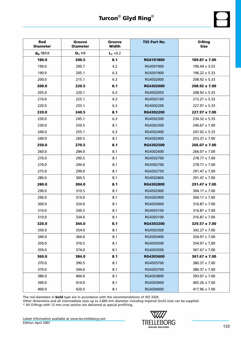
RodDiameter
GrooveDiameter
GrooveWidth
TSS Part No. O—RingSize
dN f8/h9 D1 H9 L1 +0.2
180.0
190.0
190.0
200.5
200.7
205.1
8.1
4.2
6.3
RG4101800
RG4501900
RG4301900
189.87 x 7.00
196.44 x 3.53
196.22 x 5.33
200.0
200.0
205.0
215.1
220.5
220.1
6.3
8.1
6.3
RG4502000
RG4302000
RG4502050
208.92 x 5.33
208.92 x 7.00
208.92 x 5.33
210.0
220.0
220.0
225.1
235.1
240.5
6.3
6.3
8.1
RG4502100
RG4502200
RG4302200
215.27 x 5.33
227.97 x 5.33
227.97 x 7.00
230.0
230.0
240.0
245.1
250.5
255.1
6.3
8.1
6.3
RG4502300
RG4302300
RG4502400
234.32 x 5.33
240.67 x 7.00
247.02 x 5.33
240.0
250.0
260.0
260.5
270.5
284.0
8.1
8.1
8.1
RG4302400
RG4302500
RG4302600
253.37 x 7.00
266.07 x 7.00
266.07 x 7.00
270.0
270.0
275.0
290.5
294.0
299.0
8.1
8.1
8.1
RG4502700
RG4302700
RG4302750
278.77 x 7.00
278.77 x 7.00
291.47 x 7.00
280.0
280.0
290.0
300.5
304.0
310.5
8.1
8.1
8.1
RG4502800
RG4302800
RG4502900
291.47 x 7.00
291.47 x 7.00
304.17 x 7.00
290.0
300.0
310.0
314.0
324.0
330.5
8.1
8.1
8.1
RG4302900
RG4303000
RG4503100
304.17 x 7.00
316.87 x 7.00
316.87 x 7.00
310.0
320.0
330.0
334.0
344.0
354.0
8.1
8.1
8.1
RG4303100
RG4303200
RG4303300
316.87 x 7.00
329.57 x 7.00
342.27 x 7.00
340.0
350.0
350.0
364.0
370.5
374.0
8.1
8.1
8.1
RG4303400
RG4503500
RG4303500
354.97 x 7.00
354.97 x 7.00
367.67 x 7.00
360.0
370.0
370.0
384.0
390.5
394.0
8.1
8.1
8.1
RG4303600
RG4503700
RG4303700
367.67 x 7.00
380.37 x 7.00
380.37 x 7.00
380.0
390.0
400.0
404.0
414.0
420.5
8.1
8.1
8.1
RG4303800
RG4303900
RG4504000
393.07 x 7.00
405.26 x 7.00
417.96 x 7.00
The rod diameters in bold type are in accordance with the recommendations of ISO 3320.Other dimensions and all intermediate sizes up to 2.600 mm diameter including imperial (inch) sizes can be supplied.* All O—Rings with 12 mm cross section are delivered as special profilring.
Turcon® Glyd Ring®
Latest information available at www.tss.trelleborg.comEdition April 2007
133
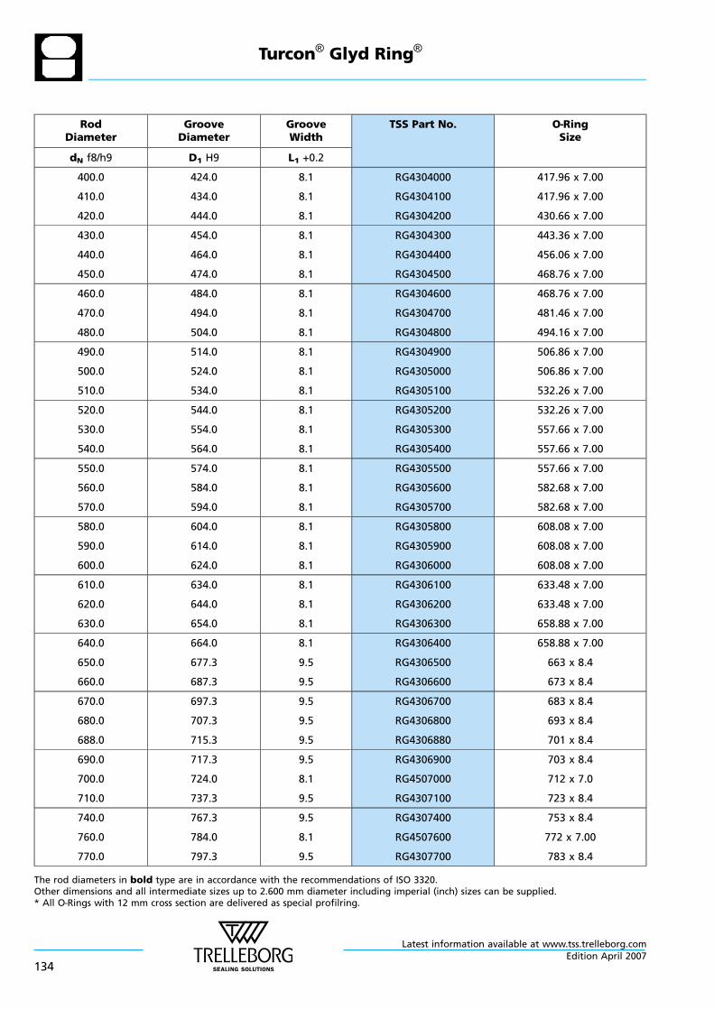
RodDiameter
GrooveDiameter
GrooveWidth
TSS Part No. O—RingSize
dN f8/h9 D1 H9 L1 +0.2
400.0
410.0
420.0
424.0
434.0
444.0
8.1
8.1
8.1
RG4304000
RG4304100
RG4304200
417.96 x 7.00
417.96 x 7.00
430.66 x 7.00
430.0
440.0
450.0
454.0
464.0
474.0
8.1
8.1
8.1
RG4304300
RG4304400
RG4304500
443.36 x 7.00
456.06 x 7.00
468.76 x 7.00
460.0
470.0
480.0
484.0
494.0
504.0
8.1
8.1
8.1
RG4304600
RG4304700
RG4304800
468.76 x 7.00
481.46 x 7.00
494.16 x 7.00
490.0
500.0
510.0
514.0
524.0
534.0
8.1
8.1
8.1
RG4304900
RG4305000
RG4305100
506.86 x 7.00
506.86 x 7.00
532.26 x 7.00
520.0
530.0
540.0
544.0
554.0
564.0
8.1
8.1
8.1
RG4305200
RG4305300
RG4305400
532.26 x 7.00
557.66 x 7.00
557.66 x 7.00
550.0
560.0
570.0
574.0
584.0
594.0
8.1
8.1
8.1
RG4305500
RG4305600
RG4305700
557.66 x 7.00
582.68 x 7.00
582.68 x 7.00
580.0
590.0
600.0
604.0
614.0
624.0
8.1
8.1
8.1
RG4305800
RG4305900
RG4306000
608.08 x 7.00
608.08 x 7.00
608.08 x 7.00
610.0
620.0
630.0
634.0
644.0
654.0
8.1
8.1
8.1
RG4306100
RG4306200
RG4306300
633.48 x 7.00
633.48 x 7.00
658.88 x 7.00
640.0
650.0
660.0
664.0
677.3
687.3
8.1
9.5
9.5
RG4306400
RG4306500
RG4306600
658.88 x 7.00
663 x 8.4
673 x 8.4
670.0
680.0
688.0
697.3
707.3
715.3
9.5
9.5
9.5
RG4306700
RG4306800
RG4306880
683 x 8.4
693 x 8.4
701 x 8.4
690.0
700.0
710.0
717.3
724.0
737.3
9.5
8.1
9.5
RG4306900
RG4507000
RG4307100
703 x 8.4
712 x 7.0
723 x 8.4
740.0
760.0
770.0
767.3
784.0
797.3
9.5
8.1
9.5
RG4307400
RG4507600
RG4307700
753 x 8.4
772 x 7.00
783 x 8.4
The rod diameters in bold type are in accordance with the recommendations of ISO 3320.Other dimensions and all intermediate sizes up to 2.600 mm diameter including imperial (inch) sizes can be supplied.* All O—Rings with 12 mm cross section are delivered as special profilring.
Turcon® Glyd Ring®
Latest information available at www.tss.trelleborg.com
134Edition April 2007
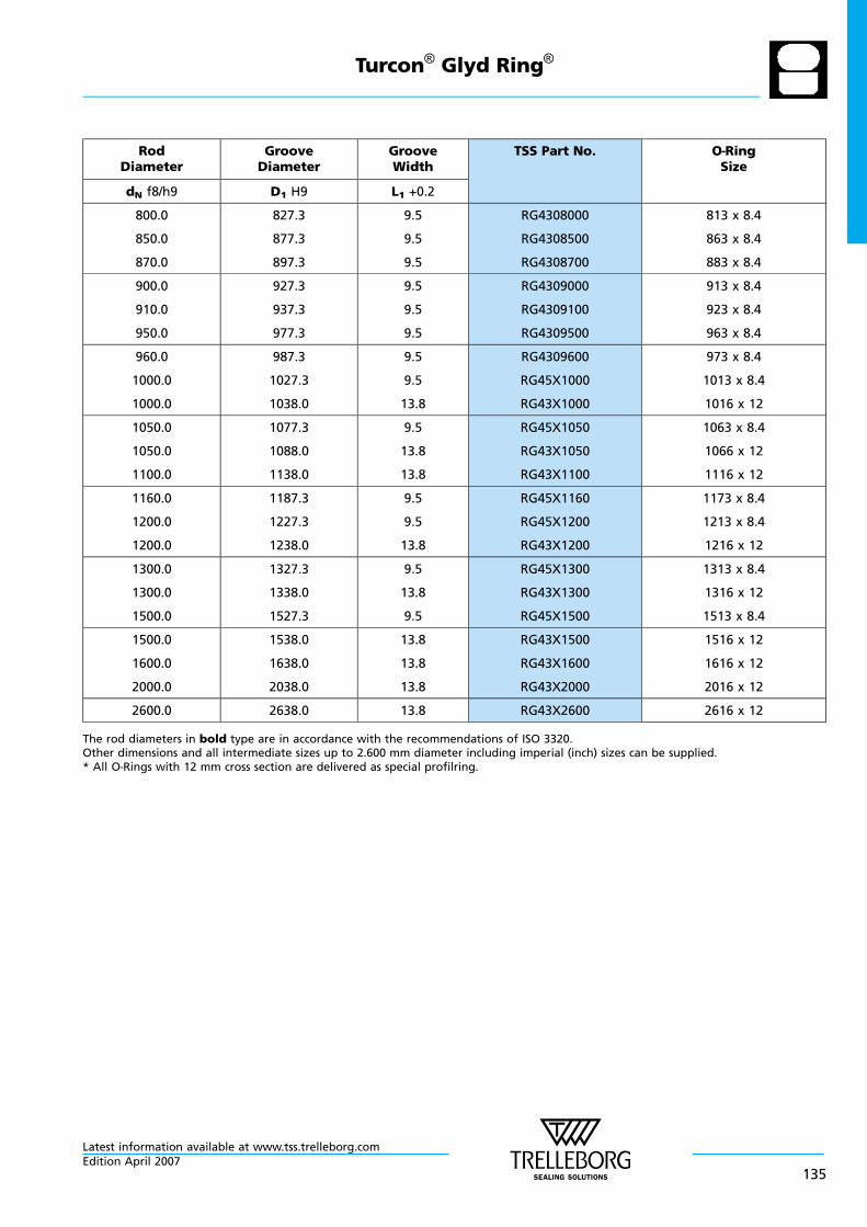
RodDiameter
GrooveDiameter
GrooveWidth
TSS Part No. O—RingSize
dN f8/h9 D1 H9 L1 +0.2
800.0
850.0
870.0
827.3
877.3
897.3
9.5
9.5
9.5
RG4308000
RG4308500
RG4308700
813 x 8.4
863 x 8.4
883 x 8.4
900.0
910.0
950.0
927.3
937.3
977.3
9.5
9.5
9.5
RG4309000
RG4309100
RG4309500
913 x 8.4
923 x 8.4
963 x 8.4
960.0
1000.0
1000.0
987.3
1027.3
1038.0
9.5
9.5
13.8
RG4309600
RG45X1000
RG43X1000
973 x 8.4
1013 x 8.4
1016 x 12
1050.0
1050.0
1100.0
1077.3
1088.0
1138.0
9.5
13.8
13.8
RG45X1050
RG43X1050
RG43X1100
1063 x 8.4
1066 x 12
1116 x 12
1160.0
1200.0
1200.0
1187.3
1227.3
1238.0
9.5
9.5
13.8
RG45X1160
RG45X1200
RG43X1200
1173 x 8.4
1213 x 8.4
1216 x 12
1300.0
1300.0
1500.0
1327.3
1338.0
1527.3
9.5
13.8
9.5
RG45X1300
RG43X1300
RG45X1500
1313 x 8.4
1316 x 12
1513 x 8.4
1500.0
1600.0
2000.0
1538.0
1638.0
2038.0
13.8
13.8
13.8
RG43X1500
RG43X1600
RG43X2000
1516 x 12
1616 x 12
2016 x 12
2600.0 2638.0 13.8 RG43X2600 2616 x 12
The rod diameters in bold type are in accordance with the recommendations of ISO 3320.Other dimensions and all intermediate sizes up to 2.600 mm diameter including imperial (inch) sizes can be supplied.* All O—Rings with 12 mm cross section are delivered as special profilring.
Turcon® Glyd Ring®
Latest information available at www.tss.trelleborg.comEdition April 2007
135
Turcon® Glyd Ring®
Latest information available at www.tss.trelleborg.com
136Edition April 2007
TURCON® GLYD RING® T
- Double Acting -
- Rubber Energised Plastic Faced Seal -
- Material -
- Turcon® and Zurcon® -
Latest information available at www.tss.trelleborg.comEdition April 2007
137

Latest information available at www.tss.trelleborg.com
138Edition April 2007
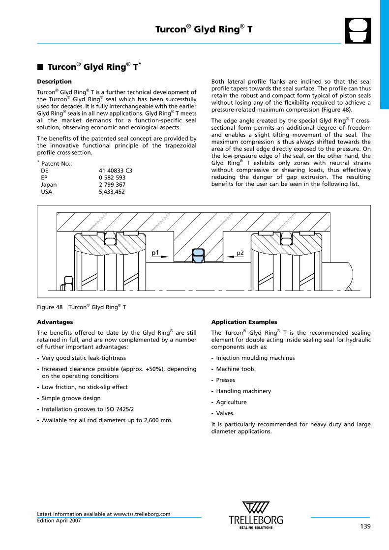
n Turcon® Glyd Ring® T*
Description
Turcon® Glyd Ring® T is a further technical development ofthe Turcon® Glyd Ring® seal which has been successfullyused for decades. It is fully interchangeable with the earlierGlyd Ring® seals in all new applications. Glyd Ring® T meetsall the market demands for a function-specific sealsolution, observing economic and ecological aspects.
The benefits of the patented seal concept are provided bythe innovative functional principle of the trapezoidalprofile cross-section.
* Patent-No.:DE 41 40833 C3EP 0 582 593Japan 2 799 367USA 5,433,452
Both lateral profile flanks are inclined so that the sealprofile tapers towards the seal surface. The profile can thusretain the robust and compact form typical of piston sealswithout losing any of the flexibility required to achieve apressure-related maximum compression (Figure 48).
The edge angle created by the special Glyd Ring® T cross-sectional form permits an additional degree of freedomand enables a slight tilting movement of the seal. Themaximum compression is thus always shifted towards thearea of the seal edge directly exposed to the pressure. Onthe low-pressure edge of the seal, on the other hand, theGlyd Ring® T exhibits only zones with neutral strainswithout compressive or shearing loads, thus effectivelyreducing the danger of gap extrusion. The resultingbenefits for the user can be seen in the following list.
p1 p2
Figure 48 Turcon® Glyd Ring® T
Advantages
The benefits offered to date by the Glyd Ring® are stillretained in full, and are now complemented by a numberof further important advantages:
- Very good static leak-tightness
- Increased clearance possible (approx. +50%), dependingon the operating conditions
- Low friction, no stick-slip effect
- Simple groove design
- Installation grooves to ISO 7425/2
- Available for all rod diameters up to 2,600 mm.
Application Examples
The Turcon® Glyd Ring® T is the recommended sealingelement for double acting inside sealing seal for hydrauliccomponents such as:
- Injection moulding machines
- Machine tools
- Presses
- Handling machinery
- Agriculture
- Valves.
It is particularly recommended for heavy duty and largediameter applications.
Turcon® Glyd Ring® T
Latest information available at www.tss.trelleborg.comEdition April 2007
139
Technical Data
Operating pressure: Up to 80 MPa
Speed: Up to 15 m/s
Temperature: -45°C to +200°C(depending on O—Ring material)
Media: Mineral oil-based hydraulicfluids, flame retardanthydraulic fluids,environmentally safehydraulic fluids (bio-oils),water, air and others,depending on the O—Ringmaterial (see Table XXXIV)
Clearance: The maximum permissibleradial clearance smax is shownin Table XXXV as a functionof the operating pressure andfunctional diameter.
Important Note:The above data are maximum values and cannotbe used at the same time. e.g. the maximumoperating speed depends on material type,pressure, temperature and gap value.Temperature range also dependent on medium.
Materials
Standard Application:
- For hydraulic components with reciprocating movementin mineral oils containing zinc or medium with goodlubricating performance.
Turcon® Seal: Turcon® T46
Energiser: O—Ring NBR 70 shore A or FKM 70Shore A depending on thetemperature
Set code: T46N or T46V
Special Application:
- Non-lubricating fluids or pneumatic applications requireself-lubricating sealing materials. Therefore werecommend:
Turcon® Seal: Turcon® T40
Energiser: O—Ring NBR 70 Shore A or FKM70 Shore A depending on thetemperature
Set code: T40N or T40V
- If rougher surface finish must be sealed, we recommend:
Zurcon® Seal: Zurcon® Z51
Energiser: O—Ring NBR 70 Shore A
Set code: Z51N
Turcon® Glyd Ring® T
Latest information available at www.tss.trelleborg.com
140Edition April 2007
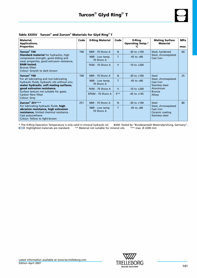
Table XXXIV Turcon® and Zurcon® Materials for Glyd Ring® T
Material,Applications,Properties
Code O—Ring Material Code O—RingOperating Temp.*
°C
Mating SurfaceMaterial
MPa
max.
Turcon® T46Standard material for hydraulics, highcompressive strength, good sliding andwear properties, good extrusion resistance,BAM tested.Bronze filledColour: Greyish to dark brown
T46 NBR - 70 Shore A N -30 to +100 Steel, hardenedSteel, chromeplatedCast iron
60
NBR - Low temp.70 Shore A
T -45 to +80
FKM - 70 Shore A V -10 to +200
Turcon® T40For all lubricating and non-lubricatinghydraulic fluids, hydraulic oils without zinc,water hydraulic, soft mating surfaces,good extrusion resistance.Surface texture not suitable for gases.Carbon fibre filledColour: Grey
T40 NBR - 70 Shore A N -30 to +100 SteelSteel, chromeplatedCast ironStainless steelAluminiumBronzeAlloys
25
NBR - Low temp.70 Shore A
T -45 to +80
FKM - 70 Shore A V -10 to +200
EPDM - 70 Shore A E** -45 to +145
Zurcon® Z51***For lubricating hydraulic fluids, highabrasion resistance, high extrusionresistance, limited chemical resistance.Cast polyurethaneColour: Yellow to light-brown
Z51 NBR - 70 Shore A N -30 to +100 SteelSteel, chromeplatedCast ironCeramic coatingStainless steel
80
NBR - Low temp.70 Shore A
T -45 to +80
* The O—Ring Operation Temperature is only valid in mineral hydraulic oil. BAM: Tested by “Bundesanstalt Materialprufung, Germany“.nn Highlighted materials are standard. ** Material not suitable for mineral oils. *** max. Ø 2200 mm
Turcon® Glyd Ring® T
Latest information available at www.tss.trelleborg.comEdition April 2007
141
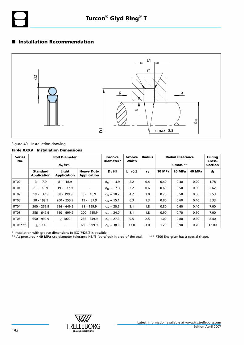
n Installation Recommendation
d2
L1
r1
p
r max. 0.3
p
D1
S
dN
Figure 49 Installation drawing
Table XXXV Installation Dimensions
SeriesNo.
Rod Diameter
dN f8/h9
GrooveDiameter*
GrooveWidth
Radius Radial Clearance
S max. **
O—RingCross-Section
StandardApplication
LightApplication
Heavy DutyApplication
D1 H9 L1 +0.2 r1 10 MPa 20 MPa 40 MPa d2
RT00 3 - 7.9 8 - 18.9 - dN + 4.9 2.2 0.4 0.40 0.30 0.20 1.78
RT01 8 - 18.9 19 - 37.9 - dN + 7.3 3.2 0.6 0.60 0.50 0.30 2.62
RT02 19 - 37.9 38 - 199.9 8 - 18.9 dN + 10.7 4.2 1.0 0.70 0.50 0.30 3.53
RT03 38 - 199.9 200 - 255.9 19 - 37.9 dN + 15.1 6.3 1.3 0.80 0.60 0.40 5.33
RT04 200 - 255.9 256 - 649.9 38 - 199.9 dN + 20.5 8.1 1.8 0.80 0.60 0.40 7.00
RT08 256 - 649.9 650 - 999.9 200 - 255.9 dN + 24.0 8.1 1.8 0.90 0.70 0.50 7.00
RT05 650 - 999.9 1000 256 - 649.9 dN + 27.3 9.5 2.5 1.00 0.80 0.60 8.40
RT06*** 1000 - 650 - 999.9 dN + 38.0 13.8 3.0 1.20 0.90 0.70 12.00
* Installation with groove dimensions to ISO 7425/2 is possible.** At pressures > 40 MPa use diameter tolerance H8/f8 (bore/rod) in area of the seal. *** RT06 Energiser has a special shape.
Turcon® Glyd Ring® T
Latest information available at www.tss.trelleborg.com
142Edition April 2007
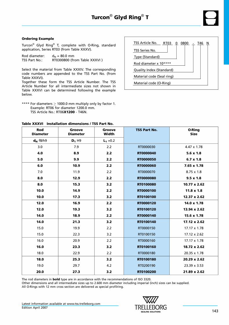
Ordering Example
Turcon® Glyd Ring® T, complete with O—Ring, standardapplication, Series RT03 (from Table XXXV).
Rod diameter: dN = 80.0 mmTSS Part No.: RT0300800 (from Table XXXVI )
Select the material from Table XXXIV. The correspondingcode numbers are appended to the TSS Part No. (fromTable XXXVI).Together these form the TSS Article Number. The TSSArticle Number for all intermediate sizes not shown inTable XXXVI can be determined following the examplebelow.
**** For diameters 1000.0 mm multiply only by factor 1.Example: RT06 for diameter 1200.0 mm.TSS Article No.: RT06X1200 - T46N.
Material code (Seal ring)
TSS Series No.
TSS Article No. T460800 N
Material code (O-Ring)
Rod diameter x 10****
RT03
Quality Index (Standard)
-
Type (Standard)
0
Table XXXVI Installation dimensions / TSS Part No.
RodDiameter
GrooveDiameter
GrooveWidth
TSS Part No. O—RingSize
dN f8/h9 D1 H9 L1 +0.2
3.0
4.0
5.0
7.9
8.9
9.9
2.2
2.2
2.2
RT0000030
RT0000040
RT0000050
4.47 x 1.78
5.6 x 1.8
6.7 x 1.8
6.0
7.0
8.0
10.9
11.9
12.9
2.2
2.2
2.2
RT0000060
RT0000070
RT0000080
7.65 x 1.78
8.75 x 1.8
9.5 x 1.8
8.0
10.0
10.0
15.3
14.9
17.3
3.2
2.2
3.2
RT0100080
RT0000100
RT0100100
10.77 x 2.62
11.8 x 1.8
12.37 x 2.62
12.0
12.0
14.0
16.9
19.3
18.9
2.2
3.2
2.2
RT0000120
RT0100120
RT0000140
14.0 x 1.78
13.94 x 2.62
15.6 x 1.78
14.0
15.0
15.0
21.3
19.9
22.3
3.2
2.2
3.2
RT0100140
RT0000150
RT0100150
17.12 x 2.62
17.17 x 1.78
17.12 x 2.62
16.0
16.0
18.0
20.9
23.3
22.9
2.2
3.2
2.2
RT0000160
RT0100160
RT0000180
17.17 x 1.78
18.72 x 2.62
20.35 x 1.78
18.0
19.0
20.0
25.3
29.7
27.3
3.2
4.2
3.2
RT0100180
RT0200190
RT0100200
20.29 x 2.62
23.39 x 3.53
21.89 x 2.62
The rod diameters in bold type are in accordance with the recommendations of ISO 3320.Other dimensions and all intermediate sizes up to 2.600 mm diameter including imperial (inch) sizes can be supplied.All O—Rings with 12 mm cross section are delivered as special profilring.
Turcon® Glyd Ring® T
Latest information available at www.tss.trelleborg.comEdition April 2007
143
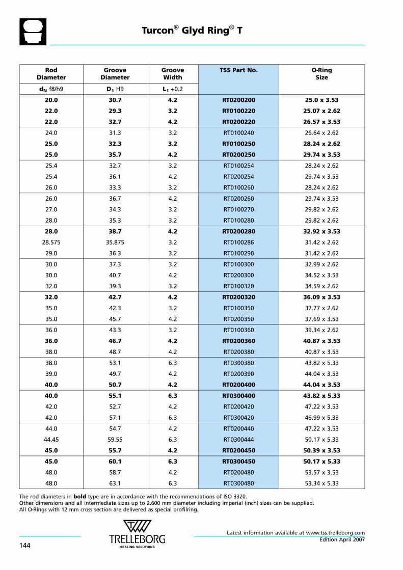
RodDiameter
GrooveDiameter
GrooveWidth
TSS Part No. O—RingSize
dN f8/h9 D1 H9 L1 +0.2
20.0
22.0
22.0
30.7
29.3
32.7
4.2
3.2
4.2
RT0200200
RT0100220
RT0200220
25.0 x 3.53
25.07 x 2.62
26.57 x 3.53
24.0
25.0
25.0
31.3
32.3
35.7
3.2
3.2
4.2
RT0100240
RT0100250
RT0200250
26.64 x 2.62
28.24 x 2.62
29.74 x 3.53
25.4
25.4
26.0
32.7
36.1
33.3
3.2
4.2
3.2
RT0100254
RT0200254
RT0100260
28.24 x 2.62
29.74 x 3.53
28.24 x 2.62
26.0
27.0
28.0
36.7
34.3
35.3
4.2
3.2
3.2
RT0200260
RT0100270
RT0100280
29.74 x 3.53
29.82 x 2.62
29.82 x 2.62
28.0
28.575
29.0
38.7
35.875
36.3
4.2
3.2
3.2
RT0200280
RT0100286
RT0100290
32.92 x 3.53
31.42 x 2.62
31.42 x 2.62
30.0
30.0
32.0
37.3
40.7
39.3
3.2
4.2
3.2
RT0100300
RT0200300
RT0100320
32.99 x 2.62
34.52 x 3.53
34.59 x 2.62
32.0
35.0
35.0
42.7
42.3
45.7
4.2
3.2
4.2
RT0200320
RT0100350
RT0200350
36.09 x 3.53
37.77 x 2.62
37.69 x 3.53
36.0
36.0
38.0
43.3
46.7
48.7
3.2
4.2
4.2
RT0100360
RT0200360
RT0200380
39.34 x 2.62
40.87 x 3.53
40.87 x 3.53
38.0
39.0
40.0
53.1
49.7
50.7
6.3
4.2
4.2
RT0300380
RT0200390
RT0200400
43.82 x 5.33
44.04 x 3.53
44.04 x 3.53
40.0
42.0
42.0
55.1
52.7
57.1
6.3
4.2
6.3
RT0300400
RT0200420
RT0300420
43.82 x 5.33
47.22 x 3.53
46.99 x 5.33
44.0
44.45
45.0
54.7
59.55
55.7
4.2
6.3
4.2
RT0200440
RT0300444
RT0200450
47.22 x 3.53
50.17 x 5.33
50.39 x 3.53
45.0
48.0
48.0
60.1
58.7
63.1
6.3
4.2
6.3
RT0300450
RT0200480
RT0300480
50.17 x 5.33
53.57 x 3.53
53.34 x 5.33
The rod diameters in bold type are in accordance with the recommendations of ISO 3320.Other dimensions and all intermediate sizes up to 2.600 mm diameter including imperial (inch) sizes can be supplied.All O—Rings with 12 mm cross section are delivered as special profilring.
Turcon® Glyd Ring® T
Latest information available at www.tss.trelleborg.com
144Edition April 2007
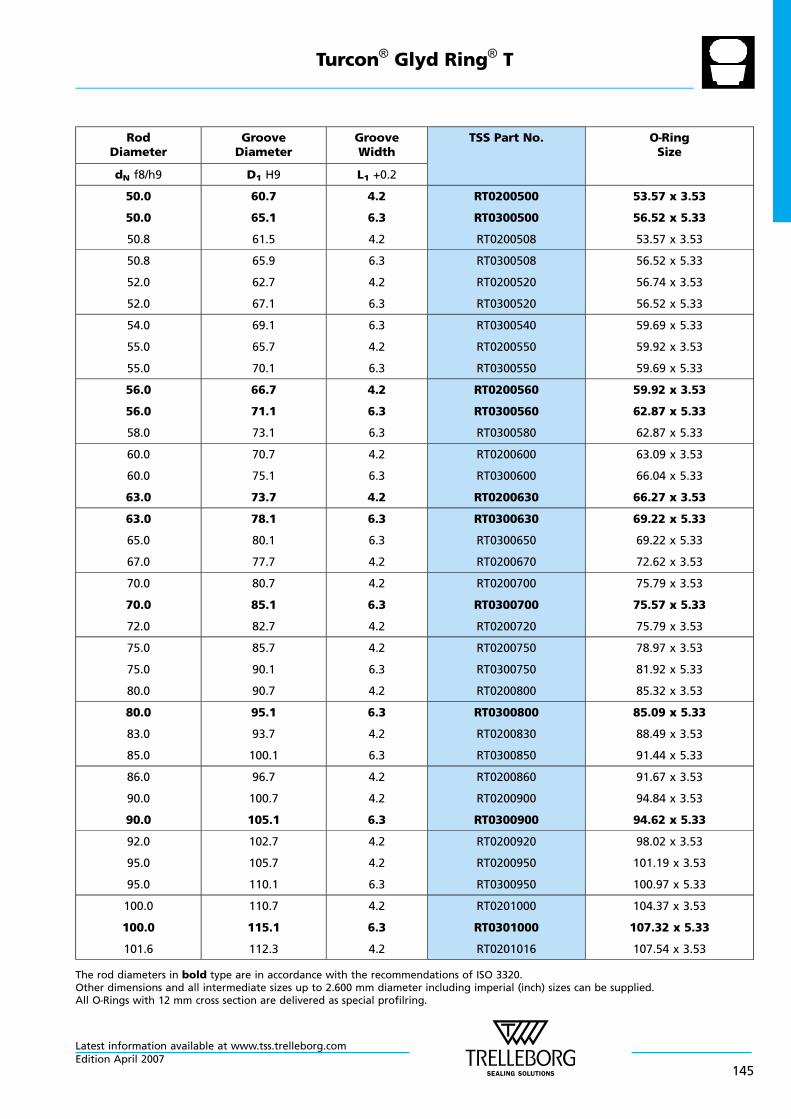
RodDiameter
GrooveDiameter
GrooveWidth
TSS Part No. O—RingSize
dN f8/h9 D1 H9 L1 +0.2
50.0
50.0
50.8
60.7
65.1
61.5
4.2
6.3
4.2
RT0200500
RT0300500
RT0200508
53.57 x 3.53
56.52 x 5.33
53.57 x 3.53
50.8
52.0
52.0
65.9
62.7
67.1
6.3
4.2
6.3
RT0300508
RT0200520
RT0300520
56.52 x 5.33
56.74 x 3.53
56.52 x 5.33
54.0
55.0
55.0
69.1
65.7
70.1
6.3
4.2
6.3
RT0300540
RT0200550
RT0300550
59.69 x 5.33
59.92 x 3.53
59.69 x 5.33
56.0
56.0
58.0
66.7
71.1
73.1
4.2
6.3
6.3
RT0200560
RT0300560
RT0300580
59.92 x 3.53
62.87 x 5.33
62.87 x 5.33
60.0
60.0
63.0
70.7
75.1
73.7
4.2
6.3
4.2
RT0200600
RT0300600
RT0200630
63.09 x 3.53
66.04 x 5.33
66.27 x 3.53
63.0
65.0
67.0
78.1
80.1
77.7
6.3
6.3
4.2
RT0300630
RT0300650
RT0200670
69.22 x 5.33
69.22 x 5.33
72.62 x 3.53
70.0
70.0
72.0
80.7
85.1
82.7
4.2
6.3
4.2
RT0200700
RT0300700
RT0200720
75.79 x 3.53
75.57 x 5.33
75.79 x 3.53
75.0
75.0
80.0
85.7
90.1
90.7
4.2
6.3
4.2
RT0200750
RT0300750
RT0200800
78.97 x 3.53
81.92 x 5.33
85.32 x 3.53
80.0
83.0
85.0
95.1
93.7
100.1
6.3
4.2
6.3
RT0300800
RT0200830
RT0300850
85.09 x 5.33
88.49 x 3.53
91.44 x 5.33
86.0
90.0
90.0
96.7
100.7
105.1
4.2
4.2
6.3
RT0200860
RT0200900
RT0300900
91.67 x 3.53
94.84 x 3.53
94.62 x 5.33
92.0
95.0
95.0
102.7
105.7
110.1
4.2
4.2
6.3
RT0200920
RT0200950
RT0300950
98.02 x 3.53
101.19 x 3.53
100.97 x 5.33
100.0
100.0
101.6
110.7
115.1
112.3
4.2
6.3
4.2
RT0201000
RT0301000
RT0201016
104.37 x 3.53
107.32 x 5.33
107.54 x 3.53
The rod diameters in bold type are in accordance with the recommendations of ISO 3320.Other dimensions and all intermediate sizes up to 2.600 mm diameter including imperial (inch) sizes can be supplied.All O—Rings with 12 mm cross section are delivered as special profilring.
Turcon® Glyd Ring® T
Latest information available at www.tss.trelleborg.comEdition April 2007
145
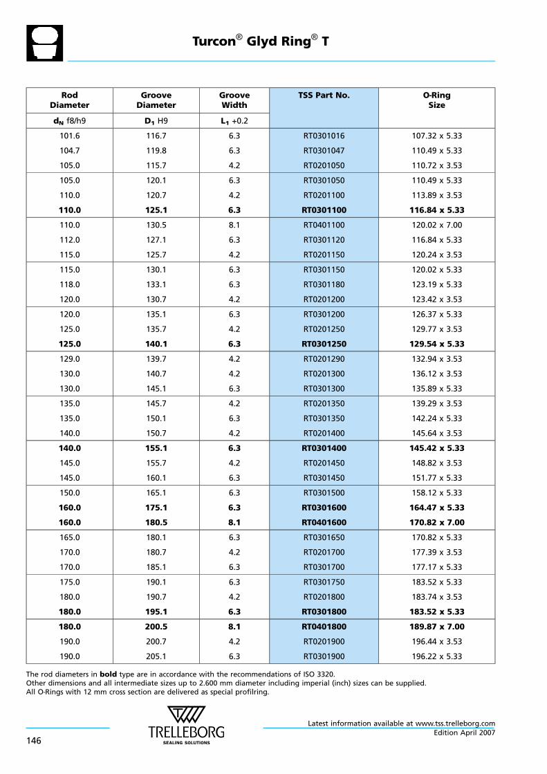
RodDiameter
GrooveDiameter
GrooveWidth
TSS Part No. O—RingSize
dN f8/h9 D1 H9 L1 +0.2
101.6
104.7
105.0
116.7
119.8
115.7
6.3
6.3
4.2
RT0301016
RT0301047
RT0201050
107.32 x 5.33
110.49 x 5.33
110.72 x 3.53
105.0
110.0
110.0
120.1
120.7
125.1
6.3
4.2
6.3
RT0301050
RT0201100
RT0301100
110.49 x 5.33
113.89 x 3.53
116.84 x 5.33
110.0
112.0
115.0
130.5
127.1
125.7
8.1
6.3
4.2
RT0401100
RT0301120
RT0201150
120.02 x 7.00
116.84 x 5.33
120.24 x 3.53
115.0
118.0
120.0
130.1
133.1
130.7
6.3
6.3
4.2
RT0301150
RT0301180
RT0201200
120.02 x 5.33
123.19 x 5.33
123.42 x 3.53
120.0
125.0
125.0
135.1
135.7
140.1
6.3
4.2
6.3
RT0301200
RT0201250
RT0301250
126.37 x 5.33
129.77 x 3.53
129.54 x 5.33
129.0
130.0
130.0
139.7
140.7
145.1
4.2
4.2
6.3
RT0201290
RT0201300
RT0301300
132.94 x 3.53
136.12 x 3.53
135.89 x 5.33
135.0
135.0
140.0
145.7
150.1
150.7
4.2
6.3
4.2
RT0201350
RT0301350
RT0201400
139.29 x 3.53
142.24 x 5.33
145.64 x 3.53
140.0
145.0
145.0
155.1
155.7
160.1
6.3
4.2
6.3
RT0301400
RT0201450
RT0301450
145.42 x 5.33
148.82 x 3.53
151.77 x 5.33
150.0
160.0
160.0
165.1
175.1
180.5
6.3
6.3
8.1
RT0301500
RT0301600
RT0401600
158.12 x 5.33
164.47 x 5.33
170.82 x 7.00
165.0
170.0
170.0
180.1
180.7
185.1
6.3
4.2
6.3
RT0301650
RT0201700
RT0301700
170.82 x 5.33
177.39 x 3.53
177.17 x 5.33
175.0
180.0
180.0
190.1
190.7
195.1
6.3
4.2
6.3
RT0301750
RT0201800
RT0301800
183.52 x 5.33
183.74 x 3.53
183.52 x 5.33
180.0
190.0
190.0
200.5
200.7
205.1
8.1
4.2
6.3
RT0401800
RT0201900
RT0301900
189.87 x 7.00
196.44 x 3.53
196.22 x 5.33
The rod diameters in bold type are in accordance with the recommendations of ISO 3320.Other dimensions and all intermediate sizes up to 2.600 mm diameter including imperial (inch) sizes can be supplied.All O—Rings with 12 mm cross section are delivered as special profilring.
Turcon® Glyd Ring® T
Latest information available at www.tss.trelleborg.com
146Edition April 2007

RodDiameter
GrooveDiameter
GrooveWidth
TSS Part No. O—RingSize
dN f8/h9 D1 H9 L1 +0.2
200.0
200.0
205.0
215.1
220.5
220.1
6.3
8.1
6.3
RT0302000
RT0402000
RT0302050
208.92 x 5.33
208.90 x 7.00
208.92 x 5.33
210.0
220.0
220.0
225.1
235.1
240.5
6.3
6.3
8.1
RT0302100
RT0302200
RT0402200
215.27 x 5.33
227.97 x 5.33
227.97 x 7.00
230.0
230.0
240.0
245.1
250.5
255.1
6.3
8.1
6.3
RT0302300
RT0402300
RT0302400
234.32 x 5.33
240.67 x 7.00
247.02 x 5.33
240.0
250.0
260.0
260.5
270.5
284.0
8.1
8.1
8.1
RT0402400
RT0402500
RT0802600
253.37 x 7.00
266.07 x 7.00
266.07 x 7.00
270.0
270.0
275.0
290.5
294.0
299.0
8.1
8.1
8.1
RT0402700
RT0802700
RT0802750
278.77 x 7.00
278.77 x 7.00
291.47 x 7.00
280.0
280.0
290.0
300.5
304.0
310.5
8.1
8.1
8.1
RT0402800
RT0802800
RT0402900
291.47 x 7.00
291.47 x 7.00
304.17 x 7.00
290.0
300.0
310.0
314.0
324.0
330.5
8.1
8.1
8.1
RT0802900
RT0803000
RT0403100
304.17 x 7.00
316.87 x 7.00
316.87 x 7.00
310.0
320.0
330.0
334.0
344.0
354.0
8.1
8.1
8.1
RT0803100
RT0803200
RT0803300
316.87 x 7.00
329.57 x 7.00
342.27 x 7.00
340.0
350.0
350.0
364.0
370.5
374.0
8.1
8.1
8.1
RT0803400
RT0403500
RT0803500
354.97 x 7.00
354.97 x 7.00
367.67 x 7.00
360.0
370.0
370.0
384.0
390.5
394.0
8.1
8.1
8.1
RT0803600
RT0403700
RT0803700
367.67 x 7.00
380.37 x 7.00
380.37 x 7.00
380.0
390.0
400.0
404.0
414.0
420.5
8.1
8.1
8.1
RT0803800
RT0803900
RT0404000
393.07 x 7.00
405.26 x 7.00
417.96 x 7.00
400.0
410.0
420.0
424.0
434.0
444.0
8.1
8.1
8.1
RT0804000
RT0804100
RT0804200
417.96 x 7.00
417.96 x 7.00
430.66 x 7.00
The rod diameters in bold type are in accordance with the recommendations of ISO 3320.Other dimensions and all intermediate sizes up to 2.600 mm diameter including imperial (inch) sizes can be supplied.All O—Rings with 12 mm cross section are delivered as special profilring.
Turcon® Glyd Ring® T
Latest information available at www.tss.trelleborg.comEdition April 2007
147
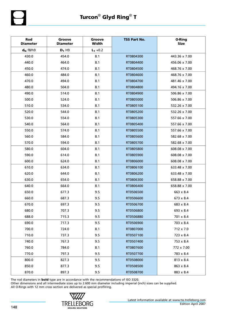
RodDiameter
GrooveDiameter
GrooveWidth
TSS Part No. O—RingSize
dN f8/h9 D1 H9 L1 +0.2
430.0
440.0
450.0
454.0
464.0
474.0
8.1
8.1
8.1
RT0804300
RT0804400
RT0804500
443.36 x 7.00
456.06 x 7.00
468.76 x 7.00
460.0
470.0
480.0
484.0
494.0
504.0
8.1
8.1
8.1
RT0804600
RT0804700
RT0804800
468.76 x 7.00
481.46 x 7.00
494.16 x 7.00
490.0
500.0
510.0
514.0
524.0
534.0
8.1
8.1
8.1
RT0804900
RT0805000
RT0805100
506.86 x 7.00
506.86 x 7.00
532.26 x 7.00
520.0
530.0
540.0
544.0
554.0
564.0
8.1
8.1
8.1
RT0805200
RT0805300
RT0805400
532.26 x 7.00
557.66 x 7.00
557.66 x 7.00
550.0
560.0
570.0
574.0
584.0
594.0
8.1
8.1
8.1
RT0805500
RT0805600
RT0805700
557.66 x 7.00
582.68 x 7.00
582.68 x 7.00
580.0
590.0
600.0
604.0
614.0
624.0
8.1
8.1
8.1
RT0805800
RT0805900
RT0806000
608.08 x 7.00
608.08 x 7.00
608.08 x 7.00
610.0
620.0
630.0
634.0
644.0
654.0
8.1
8.1
8.1
RT0806100
RT0806200
RT0806300
633.48 x 7.00
633.48 x 7.00
658.88 x 7.00
640.0
650.0
660.0
664.0
677.3
687.3
8.1
9.5
9.5
RT0806400
RT0506500
RT0506600
658.88 x 7.00
663 x 8.4
673 x 8.4
670.0
680.0
688.0
697.3
707.3
715.3
9.5
9.5
9.5
RT0506700
RT0506800
RT0506880
683 x 8.4
693 x 8.4
701 x 8.4
690.0
700.0
710.0
717.3
724.0
737.3
9.5
8.1
9.5
RT0506900
RT0807000
RT0507100
703 x 8.4
712 x 7.0
723 x 8.4
740.0
760.0
770.0
767.3
784.0
797.3
9.5
8.1
9.5
RT0507400
RT0807600
RT0507700
753 x 8.4
772 x 7.00
783 x 8.4
800.0
850.0
870.0
827.3
877.3
897.3
9.5
9.5
9.5
RT0508000
RT0508500
RT0508700
813 x 8.4
863 x 8.4
883 x 8.4
The rod diameters in bold type are in accordance with the recommendations of ISO 3320.Other dimensions and all intermediate sizes up to 2.600 mm diameter including imperial (inch) sizes can be supplied.All O—Rings with 12 mm cross section are delivered as special profilring.
Turcon® Glyd Ring® T
Latest information available at www.tss.trelleborg.com
148Edition April 2007
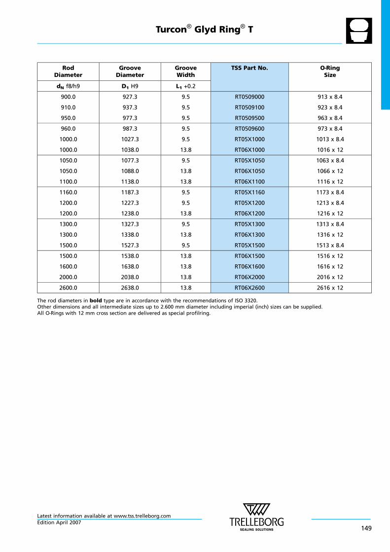
RodDiameter
GrooveDiameter
GrooveWidth
TSS Part No. O—RingSize
dN f8/h9 D1 H9 L1 +0.2
900.0
910.0
950.0
927.3
937.3
977.3
9.5
9.5
9.5
RT0509000
RT0509100
RT0509500
913 x 8.4
923 x 8.4
963 x 8.4
960.0
1000.0
1000.0
987.3
1027.3
1038.0
9.5
9.5
13.8
RT0509600
RT05X1000
RT06X1000
973 x 8.4
1013 x 8.4
1016 x 12
1050.0
1050.0
1100.0
1077.3
1088.0
1138.0
9.5
13.8
13.8
RT05X1050
RT06X1050
RT06X1100
1063 x 8.4
1066 x 12
1116 x 12
1160.0
1200.0
1200.0
1187.3
1227.3
1238.0
9.5
9.5
13.8
RT05X1160
RT05X1200
RT06X1200
1173 x 8.4
1213 x 8.4
1216 x 12
1300.0
1300.0
1500.0
1327.3
1338.0
1527.3
9.5
13.8
9.5
RT05X1300
RT06X1300
RT05X1500
1313 x 8.4
1316 x 12
1513 x 8.4
1500.0
1600.0
2000.0
1538.0
1638.0
2038.0
13.8
13.8
13.8
RT06X1500
RT06X1600
RT06X2000
1516 x 12
1616 x 12
2016 x 12
2600.0 2638.0 13.8 RT06X2600 2616 x 12
The rod diameters in bold type are in accordance with the recommendations of ISO 3320.Other dimensions and all intermediate sizes up to 2.600 mm diameter including imperial (inch) sizes can be supplied.All O—Rings with 12 mm cross section are delivered as special profilring.
Turcon® Glyd Ring® T
Latest information available at www.tss.trelleborg.comEdition April 2007
149

Turcon® Glyd Ring® T
Latest information available at www.tss.trelleborg.com
150Edition April 2007
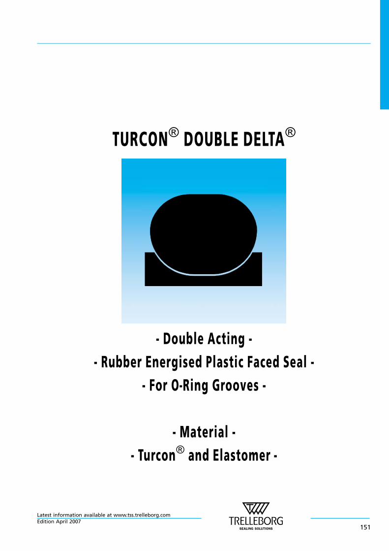
TURCON® DOUBLE DELTA®
- Double Acting -
- Rubber Energised Plastic Faced Seal -
- For O—Ring Grooves -
- Material -
- Turcon® and Elastomer -
Latest information available at www.tss.trelleborg.comEdition April 2007
151

Latest information available at www.tss.trelleborg.com
152Edition April 2007
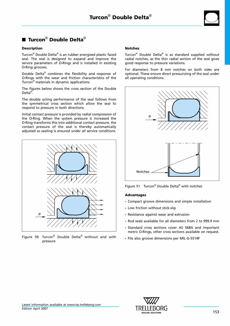
n Turcon® Double Delta®
Description
Turcon® Double Delta® is an rubber energised plastic facedseal. The seal is designed to expand and improve theservice parameters of O—Rings and is installed in existingO—Ring grooves.
Double Delta® combines the flexibility and response ofO—Rings with the wear and friction characteristics of theTurcon® materials in dynamic applications.
The figures below shows the cross section of the DoubleDelta®.
The double acting performance of the seal follows fromthe symmetrical cross section which allow the seal torespond to pressure in both directions.
Initial contact pressure is provided by radial compression ofthe O—Ring. When the system pressure is increased theO—Ring transforms this into additional contact pressure, thecontact pressure of the seal is thereby automaticallyadjusted so sealing is ensured under all service conditions.
p
Figure 50 Turcon® Double Delta® without and withpressure
Notches
Turcon® Double Delta® is as standard supplied withoutradial notches, as the thin radial section of the seal givesgood response to pressure variations.
For diameters from 8 mm notches on both sides areoptional. These ensure direct pressurizing of the seal underall operating conditions.
Notches
p
Figure 51 Turcon® Double Delta® with notches
Advantages
- Compact groove dimensions and simple installation
- Low friction without stick-slip
- Resistance against wear and extrusion
- Rod seals available for all diameters from 2 to 999.9 mm
- Standard cross sections cover AS 568A and importantmetric O—Rings, other cross sections available on request.
- Fits also groove dimensions per MIL-G-5514F
Turcon® Double Delta®
Latest information available at www.tss.trelleborg.comEdition April 2007
153
Application Examples
The Turcon® Double Delta® is preferably used as a doubleacting seal for hydraulic and pneumatic equipment insectors such as:
- Machine tools
- Handling devices
- Manipulators
- Valves
- Chemical process equipments
It is particular recommended for light duty and smalldiameter applications.
Technical Data
Operating conditions
Pressure: Up to 35 MPa
Velocity: Up to 15 m/s
Temperature: -45°C to +200°C(according to O—Ring material)
Media: Mineral oil, Non-flammable fluids,Environmentally safe fluids andothers according to O—Ring material.
Important Note:The above data are maximum values and cannotbe used at the same time. e.g. the maximumoperating speed depends on material type,pressure, temperature and gap value.Temperature range also dependent on medium.
Turcon® Double Delta®
Latest information available at www.tss.trelleborg.com
154Edition April 2007
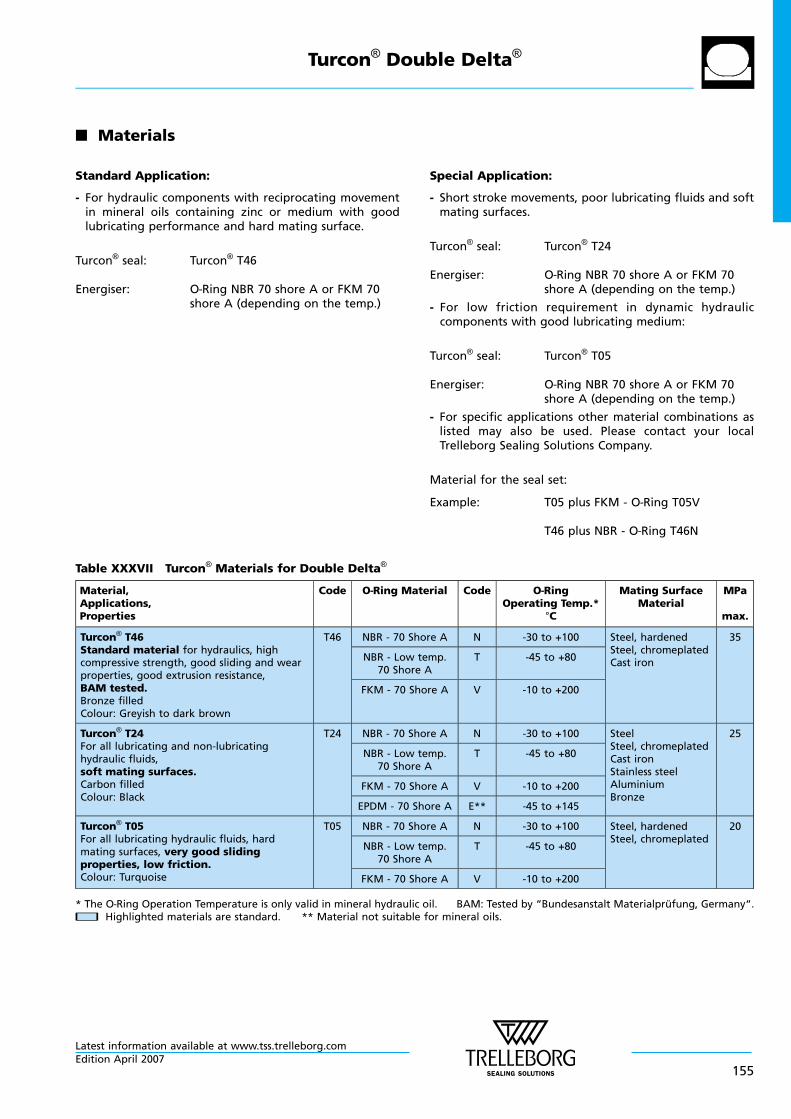
n Materials
Standard Application:
- For hydraulic components with reciprocating movementin mineral oils containing zinc or medium with goodlubricating performance and hard mating surface.
Turcon® seal: Turcon® T46
Energiser: O—Ring NBR 70 shore A or FKM 70shore A (depending on the temp.)
Special Application:
- Short stroke movements, poor lubricating fluids and softmating surfaces.
Turcon® seal: Turcon® T24
Energiser: O—Ring NBR 70 shore A or FKM 70shore A (depending on the temp.)
- For low friction requirement in dynamic hydrauliccomponents with good lubricating medium:
Turcon® seal: Turcon® T05
Energiser: O—Ring NBR 70 shore A or FKM 70shore A (depending on the temp.)
- For specific applications other material combinations aslisted may also be used. Please contact your localTrelleborg Sealing Solutions Company.
Material for the seal set:
Example: T05 plus FKM - O—Ring T05V
T46 plus NBR - O—Ring T46N
Table XXXVII Turcon® Materials for Double Delta®
Material,Applications,Properties
Code O—Ring Material Code O—RingOperating Temp.*
°C
Mating SurfaceMaterial
MPa
max.
Turcon® T46Standard material for hydraulics, highcompressive strength, good sliding and wearproperties, good extrusion resistance,BAM tested.Bronze filledColour: Greyish to dark brown
T46 NBR - 70 Shore A N -30 to +100 Steel, hardenedSteel, chromeplatedCast iron
35
NBR - Low temp.70 Shore A
T -45 to +80
FKM - 70 Shore A V -10 to +200
Turcon® T24For all lubricating and non-lubricatinghydraulic fluids,soft mating surfaces.Carbon filledColour: Black
T24 NBR - 70 Shore A N -30 to +100 SteelSteel, chromeplatedCast ironStainless steelAluminiumBronze
25
NBR - Low temp.70 Shore A
T -45 to +80
FKM - 70 Shore A V -10 to +200
EPDM - 70 Shore A E** -45 to +145
Turcon® T05For all lubricating hydraulic fluids, hardmating surfaces, very good slidingproperties, low friction.Colour: Turquoise
T05 NBR - 70 Shore A N -30 to +100 Steel, hardenedSteel, chromeplated
20
NBR - Low temp.70 Shore A
T -45 to +80
FKM - 70 Shore A V -10 to +200
* The O—Ring Operation Temperature is only valid in mineral hydraulic oil. BAM: Tested by “Bundesanstalt Materialprufung, Germany“.nn Highlighted materials are standard. ** Material not suitable for mineral oils.
Turcon® Double Delta®
Latest information available at www.tss.trelleborg.comEdition April 2007
155
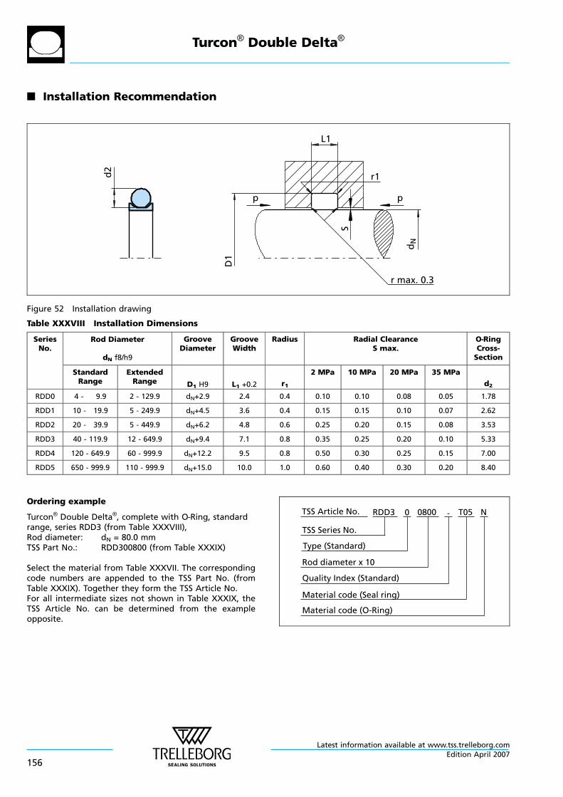
n Installation Recommendation
r max. 0.3
D1
dN
d2
L1
r1
pp
S
Figure 52 Installation drawing
Table XXXVIII Installation Dimensions
SeriesNo.
Rod Diameter
dN f8/h9
GrooveDiameter
GrooveWidth
Radius Radial ClearanceS max.
O—RingCross-Section
StandardRange
ExtendedRange D1 H9 L1 +0.2 r1
2 MPa 10 MPa 20 MPa 35 MPa
d2
RDD0 4 - 9.9 2 - 129.9 dN+2.9 2.4 0.4 0.10 0.10 0.08 0.05 1.78
RDD1 10 - 19.9 5 - 249.9 dN+4.5 3.6 0.4 0.15 0.15 0.10 0.07 2.62
RDD2 20 - 39.9 5 - 449.9 dN+6.2 4.8 0.6 0.25 0.20 0.15 0.08 3.53
RDD3 40 - 119.9 12 - 649.9 dN+9.4 7.1 0.8 0.35 0.25 0.20 0.10 5.33
RDD4 120 - 649.9 60 - 999.9 dN+12.2 9.5 0.8 0.50 0.30 0.25 0.15 7.00
RDD5 650 - 999.9 110 - 999.9 dN+15.0 10.0 1.0 0.60 0.40 0.30 0.20 8.40
Ordering example
Turcon® Double Delta®, complete with O—Ring, standardrange, series RDD3 (from Table XXXVIII),Rod diameter: dN = 80.0 mmTSS Part No.: RDD300800 (from Table XXXIX)
Select the material from Table XXXVII. The correspondingcode numbers are appended to the TSS Part No. (fromTable XXXIX). Together they form the TSS Article No.For all intermediate sizes not shown in Table XXXIX, theTSS Article No. can be determined from the exampleopposite.
Material code (Seal ring)
TSS Series No.
TSS Article No. T050800 N
Material code (O-Ring)
Rod diameter x 10
RDD3
Quality Index (Standard)
-
Type (Standard)
0
Turcon® Double Delta®
Latest information available at www.tss.trelleborg.com
156Edition April 2007
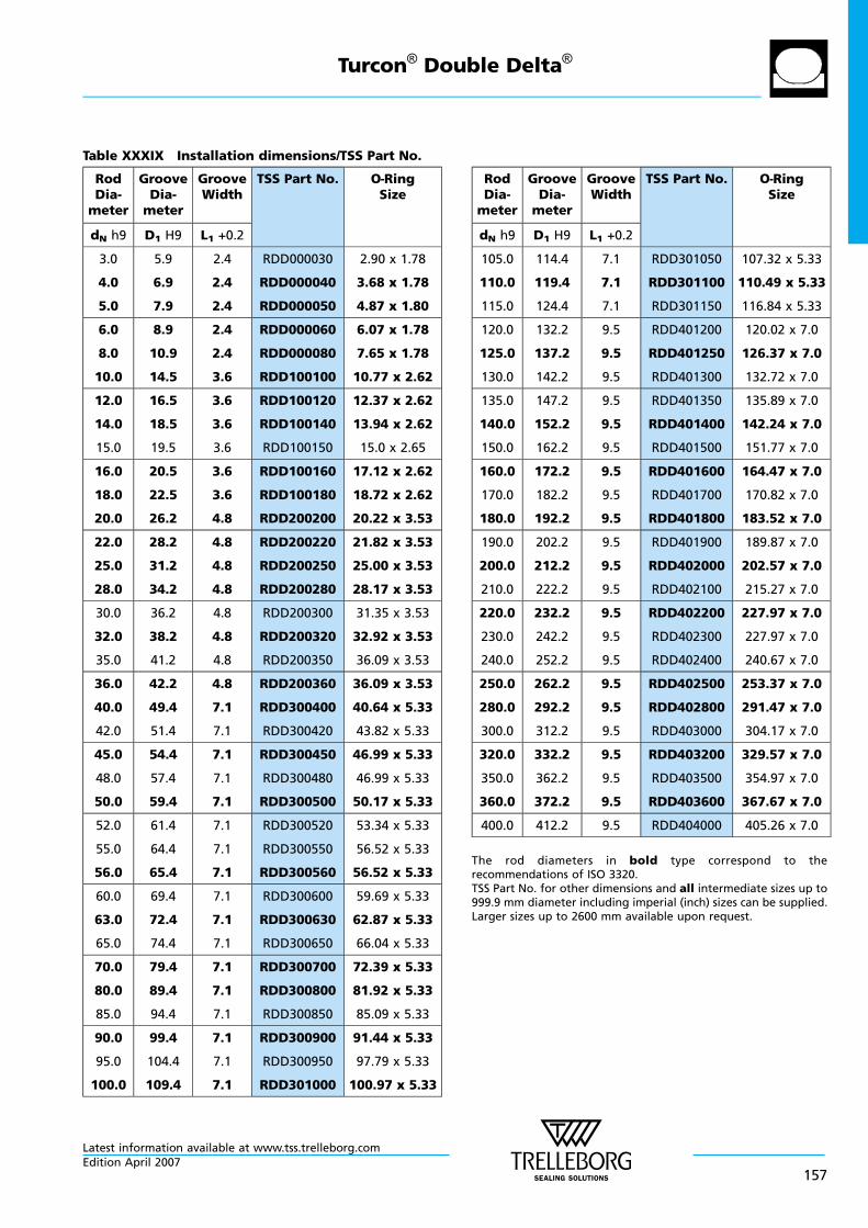
Table XXXIX Installation dimensions/TSS Part No.
RodDia-meter
GrooveDia-meter
GrooveWidth
TSS Part No. O—RingSize
dN h9 D1 H9 L1 +0.2
3.0
4.0
5.0
5.9
6.9
7.9
2.4
2.4
2.4
RDD000030
RDD000040
RDD000050
2.90 x 1.78
3.68 x 1.78
4.87 x 1.80
6.0
8.0
10.0
8.9
10.9
14.5
2.4
2.4
3.6
RDD000060
RDD000080
RDD100100
6.07 x 1.78
7.65 x 1.78
10.77 x 2.62
12.0
14.0
15.0
16.5
18.5
19.5
3.6
3.6
3.6
RDD100120
RDD100140
RDD100150
12.37 x 2.62
13.94 x 2.62
15.0 x 2.65
16.0
18.0
20.0
20.5
22.5
26.2
3.6
3.6
4.8
RDD100160
RDD100180
RDD200200
17.12 x 2.62
18.72 x 2.62
20.22 x 3.53
22.0
25.0
28.0
28.2
31.2
34.2
4.8
4.8
4.8
RDD200220
RDD200250
RDD200280
21.82 x 3.53
25.00 x 3.53
28.17 x 3.53
30.0
32.0
35.0
36.2
38.2
41.2
4.8
4.8
4.8
RDD200300
RDD200320
RDD200350
31.35 x 3.53
32.92 x 3.53
36.09 x 3.53
36.0
40.0
42.0
42.2
49.4
51.4
4.8
7.1
7.1
RDD200360
RDD300400
RDD300420
36.09 x 3.53
40.64 x 5.33
43.82 x 5.33
45.0
48.0
50.0
54.4
57.4
59.4
7.1
7.1
7.1
RDD300450
RDD300480
RDD300500
46.99 x 5.33
46.99 x 5.33
50.17 x 5.33
52.0
55.0
56.0
61.4
64.4
65.4
7.1
7.1
7.1
RDD300520
RDD300550
RDD300560
53.34 x 5.33
56.52 x 5.33
56.52 x 5.33
60.0
63.0
65.0
69.4
72.4
74.4
7.1
7.1
7.1
RDD300600
RDD300630
RDD300650
59.69 x 5.33
62.87 x 5.33
66.04 x 5.33
70.0
80.0
85.0
79.4
89.4
94.4
7.1
7.1
7.1
RDD300700
RDD300800
RDD300850
72.39 x 5.33
81.92 x 5.33
85.09 x 5.33
90.0
95.0
100.0
99.4
104.4
109.4
7.1
7.1
7.1
RDD300900
RDD300950
RDD301000
91.44 x 5.33
97.79 x 5.33
100.97 x 5.33
RodDia-meter
GrooveDia-meter
GrooveWidth
TSS Part No. O—RingSize
dN h9 D1 H9 L1 +0.2
105.0
110.0
115.0
114.4
119.4
124.4
7.1
7.1
7.1
RDD301050
RDD301100
RDD301150
107.32 x 5.33
110.49 x 5.33
116.84 x 5.33
120.0
125.0
130.0
132.2
137.2
142.2
9.5
9.5
9.5
RDD401200
RDD401250
RDD401300
120.02 x 7.0
126.37 x 7.0
132.72 x 7.0
135.0
140.0
150.0
147.2
152.2
162.2
9.5
9.5
9.5
RDD401350
RDD401400
RDD401500
135.89 x 7.0
142.24 x 7.0
151.77 x 7.0
160.0
170.0
180.0
172.2
182.2
192.2
9.5
9.5
9.5
RDD401600
RDD401700
RDD401800
164.47 x 7.0
170.82 x 7.0
183.52 x 7.0
190.0
200.0
210.0
202.2
212.2
222.2
9.5
9.5
9.5
RDD401900
RDD402000
RDD402100
189.87 x 7.0
202.57 x 7.0
215.27 x 7.0
220.0
230.0
240.0
232.2
242.2
252.2
9.5
9.5
9.5
RDD402200
RDD402300
RDD402400
227.97 x 7.0
227.97 x 7.0
240.67 x 7.0
250.0
280.0
300.0
262.2
292.2
312.2
9.5
9.5
9.5
RDD402500
RDD402800
RDD403000
253.37 x 7.0
291.47 x 7.0
304.17 x 7.0
320.0
350.0
360.0
332.2
362.2
372.2
9.5
9.5
9.5
RDD403200
RDD403500
RDD403600
329.57 x 7.0
354.97 x 7.0
367.67 x 7.0
400.0 412.2 9.5 RDD404000 405.26 x 7.0
The rod diameters in bold type correspond to therecommendations of ISO 3320.TSS Part No. for other dimensions and all intermediate sizes up to999.9 mm diameter including imperial (inch) sizes can be supplied.Larger sizes up to 2600 mm available upon request.
Turcon® Double Delta®
Latest information available at www.tss.trelleborg.comEdition April 2007
157
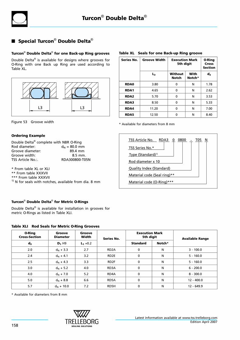
n Special Turcon® Double Delta®
Turcon® Double Delta® for one Back-up Ring grooves
Double Delta® is available for designs where grooves forO—Ring with one Back up Ring are used according toTable XL.
L3L3
Figure 53 Groove width
Table XL Seals for one Back-up Ring groove
Series No. Groove Width Execution Mark5th digit
O—RingCrossSection
L3 WithoutNotch
WithNotch*
d2
RDA0 3.80 0 N 1.78
RDA1 4.65 0 N 2.62
RDA2 5.70 0 N 3.53
RDA3 8.50 0 N 5.33
RDA4 11.20 0 N 7.00
RDA5 12.50 0 N 8.40
* Available for diameters from 8 mm
Ordering Example
Double Delta® complete with NBR O—RingRod diameter: dN = 80.0 mmGroove diameter: 89.4 mmGroove width: 8.5 mm.TSS Article No.:. RDA300800-T05N
* From table XL or XLI** From table XXXVII*** From table XXXVII1) N for seals with notches, available from dia. 8 mm
Material code (Seal ring)**
TSS Series No.*
TSS Article No. T050800 N
Material code (O-Ring)***
Rod diameter x 10
RDA3
Quality Index (Standard)
-
Type (Standard)1)
0
Turcon® Double Delta® for Metric O—Rings
Double Delta® is available for installation in grooves formetric O—Rings as listed in Table XLI.
Table XLI Rod Seals for Metric O—Ring Grooves
O—RingCross-Section
GrooveDiameter
GrooveWidth
Series No.
Execution Mark5th digit
Available Range
d2 D1 H9 L1 +0.2 Standard Notch*
2.0 dN + 3.3 2.7 RD2A 0 N 3 - 100.0
2.4 dN + 4.1 3.2 RD2E 0 N 5 - 160.0
2.5 dN + 4.3 3.3 RD2F 0 N 5 - 160.0
3.0 dN + 5.2 4.0 RD3A 0 N 6 - 200.0
4.0 dN + 7.0 5.2 RD4A 0 N 8 - 300.0
5.0 dN + 8.8 6.6 RD5A 0 N 12 - 400.0
5.7 dN + 10.0 7.2 RD5H 0 N 12 - 649.9
* Available for diameters from 8 mm
Turcon® Double Delta®
Latest information available at www.tss.trelleborg.com
158Edition April 2007
NON STANDARDSEALS
- Available upon Request -
- Old Series -
- Special Series -
Latest information available at www.tss.trelleborg.comEdition April 2007
159

Latest information available at www.tss.trelleborg.com
160Edition April 2007
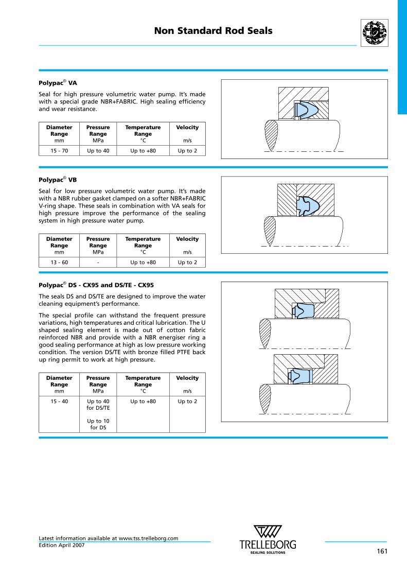
Polypac® VA
Seal for high pressure volumetric water pump. It’s madewith a special grade NBR+FABRIC. High sealing efficiencyand wear resistance.
DiameterRangemm
PressureRangeMPa
TemperatureRange
°C
Velocity
m/s
15 - 70 Up to 40 Up to +80 Up to 2
Polypac® VB
Seal for low pressure volumetric water pump. It’s madewith a NBR rubber gasket clamped on a softer NBR+FABRICV-ring shape. These seals in combination with VA seals forhigh pressure improve the performance of the sealingsystem in high pressure water pump.
DiameterRangemm
PressureRangeMPa
TemperatureRange
°C
Velocity
m/s
13 - 60 - Up to +80 Up to 2
Polypac® DS - CX95 and DS/TE - CX95
The seals DS and DS/TE are designed to improve the watercleaning equipment’s performance.
The special profile can withstand the frequent pressurevariations, high temperatures and critical lubrication. The Ushaped sealing element is made out of cotton fabricreinforced NBR and provide with a NBR energiser ring agood sealing performance at high as low pressure workingcondition. The version DS/TE with bronze filled PTFE backup ring permit to work at high pressure.
DiameterRangemm
PressureRangeMPa
TemperatureRange
°C
Velocity
m/s
15 - 40 Up to 40for DS/TE
Up to 10for DS
Up to +80 Up to 2
Non Standard Rod Seals
Latest information available at www.tss.trelleborg.comEdition April 2007
161
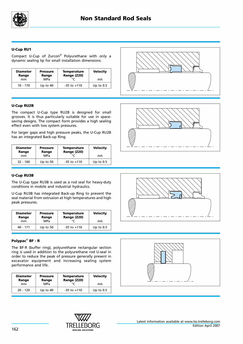
U-Cup RU1
Compact U-Cup of Zurcon® Polyurethane with only adynamic sealing lip for small installation dimensions.
DiameterRangemm
PressureRangeMPa
TemperatureRange (Z20)
°C
Velocity
m/s
10 - 170 Up to 40 -35 to +110 Up to 0.5
U-Cup RU2B
The compact U-Cup type RU2B is designed for smallgrooves. It is thus particularly suitable for use in space-saving designs. The compact form provides a high sealingeffect even with low system pressures.
For larger gaps and high pressure peaks, the U-Cup RU2Bhas an integrated Back-up Ring.
DiameterRangemm
PressureRangeMPa
TemperatureRange (Z20)
°C
Velocity
m/s
32 - 160 Up to 50 -35 to +110 Up to 0.5
U-Cup RU3B
The U-Cup type RU3B is used as a rod seal for heavy-dutyconditions in mobile and industrial hydraulics.
U-Cup RU3B has integrated Back-up Ring to prevent theseal material from extrusion at high temperatures and highpeak pressures.
DiameterRangemm
PressureRangeMPa
TemperatureRange (Z20)
°C
Velocity
m/s
40 - 171 Up to 50 -35 to +110 Up to 0.5
Polypac® BF - R
The BF-R (buffer ring), polyurethane rectangular sectionring is used in addition to the polyurethane rod U-seal inorder to reduce the peak of pressure generally present inexcavator equipment and increasing sealing systemperformance and life.
DiameterRangemm
PressureRangeMPa
TemperatureRange (Z20)
°C
Velocity
m/s
20 - 120 Up to 40 -35 to +110 Up to 0.5
Non Standard Rod Seals
Latest information available at www.tss.trelleborg.com
162Edition April 2007
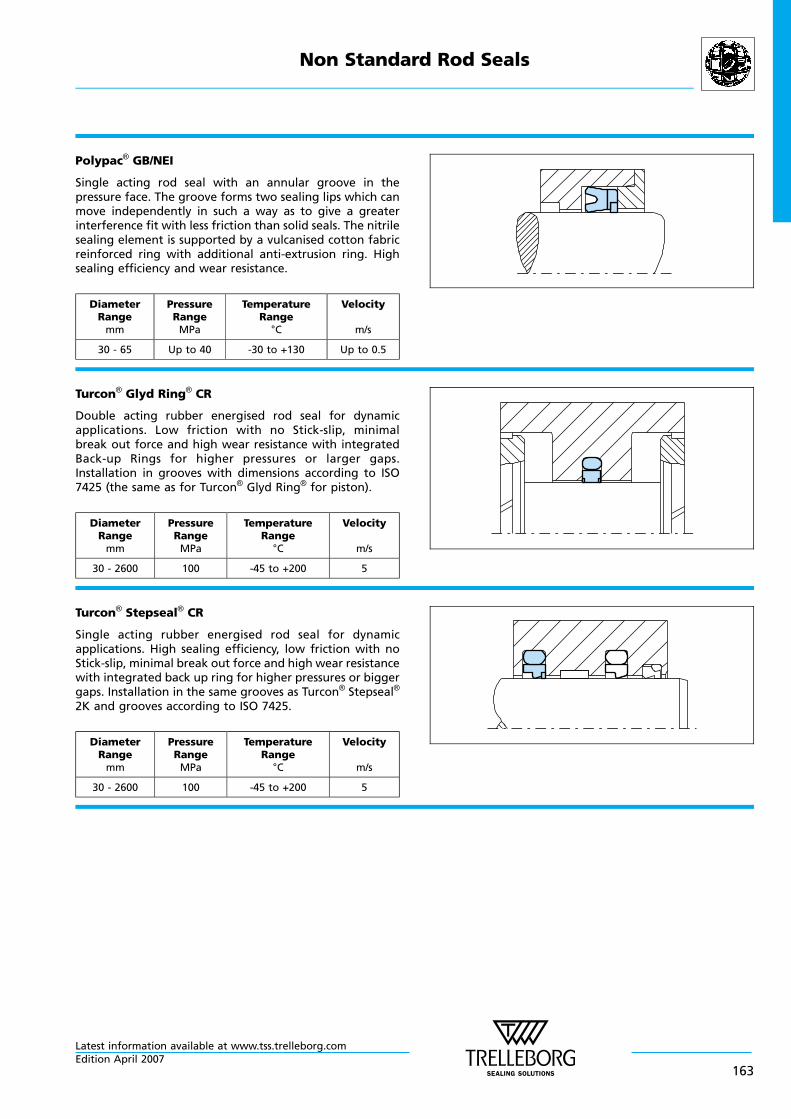
Polypac® GB/NEI
Single acting rod seal with an annular groove in thepressure face. The groove forms two sealing lips which canmove independently in such a way as to give a greaterinterference fit with less friction than solid seals. The nitrilesealing element is supported by a vulcanised cotton fabricreinforced ring with additional anti-extrusion ring. Highsealing efficiency and wear resistance.
DiameterRangemm
PressureRangeMPa
TemperatureRange
°C
Velocity
m/s
30 - 65 Up to 40 -30 to +130 Up to 0.5
Turcon® Glyd Ring® CR
Double acting rubber energised rod seal for dynamicapplications. Low friction with no Stick-slip, minimalbreak out force and high wear resistance with integratedBack-up Rings for higher pressures or larger gaps.Installation in grooves with dimensions according to ISO7425 (the same as for Turcon® Glyd Ring® for piston).
DiameterRangemm
PressureRangeMPa
TemperatureRange
°C
Velocity
m/s
30 - 2600 100 -45 to +200 5
Turcon® Stepseal® CR
Single acting rubber energised rod seal for dynamicapplications. High sealing efficiency, low friction with noStick-slip, minimal break out force and high wear resistancewith integrated back up ring for higher pressures or biggergaps. Installation in the same grooves as Turcon® Stepseal®
2K and grooves according to ISO 7425.
DiameterRangemm
PressureRangeMPa
TemperatureRange
°C
Velocity
m/s
30 - 2600 100 -45 to +200 5
Non Standard Rod Seals
Latest information available at www.tss.trelleborg.comEdition April 2007
163
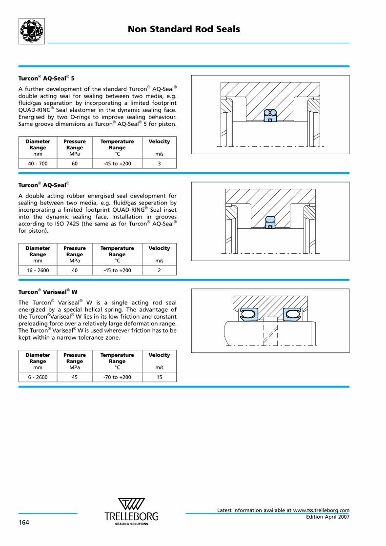
Turcon® AQ-Seal® 5
A further development of the standard Turcon® AQ-Seal®
double acting seal for sealing between two media, e.g.fluid/gas separation by incorporating a limited footprintQUAD-RING® Seal elastomer in the dynamic sealing face.Energised by two O-rings to improve sealing behaviour.Same groove dimensions as Turcon® AQ-Seal® 5 for piston.
DiameterRangemm
PressureRangeMPa
TemperatureRange
°C
Velocity
m/s
40 - 700 60 -45 to +200 3
Turcon® AQ-Seal®
A double acting rubber energised seal development forsealing between two media, e.g. fluid/gas seperation byincorporating a limited footprint QUAD-RING® Seal insetinto the dynamic sealing face. Installation in groovesaccording to ISO 7425 (the same as for Turcon® AQ-Seal®
for piston).
DiameterRangemm
PressureRangeMPa
TemperatureRange
°C
Velocity
m/s
16 - 2600 40 -45 to +200 2
Turcon® Variseal® W
The Turcon® Variseal® W is a single acting rod sealenergized by a special helical spring. The advantage ofthe Turcon®Variseal® W lies in its low friction and constantpreloading force over a relatively large deformation range.The Turcon® Variseal® W is used wherever friction has to bekept within a narrow tolerance zone.
DiameterRangemm
PressureRangeMPa
TemperatureRange
°C
Velocity
m/s
6 - 2600 45 -70 to +200 15
Non Standard Rod Seals
Latest information available at www.tss.trelleborg.com
164Edition April 2007
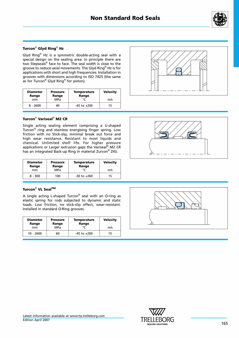
Turcon® Glyd Ring® Hz
Glyd Ring® Hz is a symmetric double-acting seal with aspecial design on the sealing area. In principle there aretwo Stepseals® face to face. The seal width is close to thegroove to reduce axial movements. The Glyd Ring® Hz is forapplications with short and high frequencies. Installation ingrooves with dimensions according to ISO 7425 (the sameas for Turcon® Glyd Ring® for piston).
DiameterRangemm
PressureRangeMPa
TemperatureRange
°C
Velocity
m/s
8 - 2600 40 -45 to +200 15
Turcon® Variseal® M2 CR
Single acting sealing element comprising a U-shapedTurcon® ring and stainless energising finger spring. Lowfriction with no Stick-slip, minimal break out force andhigh wear resistance. Resistant to most liquids andchemical. Unlimited shelf life. For higher pressureapplications or Larger extrusion gaps the Variseal® M2 CRhas an integrated Back-up Ring in material Zurcon® Z43.
DiameterRangemm
PressureRangeMPa
TemperatureRange
°C
Velocity
m/s
8 - 300 100 -30 to +260 15
Turcon® VL SealTM
A single acting L-shaped Turcon® seal with an O-ring aselastic spring for rods subjected to dynamic and staticloads. Low friction, no stick-slip effect, wear-resistant.Installed in standard O—Ring grooves.
DiameterRangemm
PressureRangeMPa
TemperatureRange
°C
Velocity
m/s
10 - 2600 60 -45 to +200 15
Non Standard Rod Seals
Latest information available at www.tss.trelleborg.comEdition April 2007
165
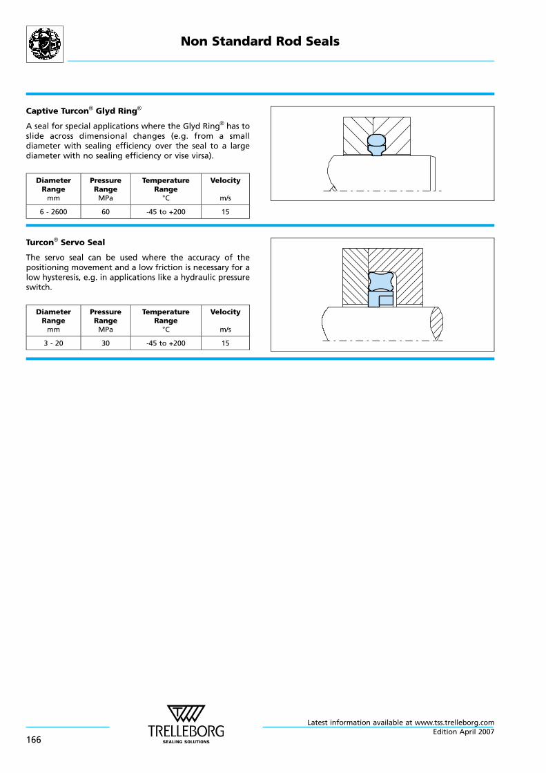
Captive Turcon® Glyd Ring®
A seal for special applications where the Glyd Ring® has toslide across dimensional changes (e.g. from a smalldiameter with sealing efficiency over the seal to a largediameter with no sealing efficiency or vise virsa).
DiameterRangemm
PressureRangeMPa
TemperatureRange
°C
Velocity
m/s
6 - 2600 60 -45 to +200 15
Turcon® Servo Seal
The servo seal can be used where the accuracy of thepositioning movement and a low friction is necessary for alow hysteresis, e.g. in applications like a hydraulic pressureswitch.
DiameterRangemm
PressureRangeMPa
TemperatureRange
°C
Velocity
m/s
3 - 20 30 -45 to +200 15
Non Standard Rod Seals
Latest information available at www.tss.trelleborg.com
166Edition April 2007

www.tss.trelleborg.com
Europe Telephone
AUSTRIA - Vienna +43 (0) 1 406 47 33(ALBANIA, BOSNIA AND HERZEGOVINA, MACEDONIA, SERBIA AND MONTENEGRO, SLOVENIA)
BELGIUM - Dion-Valmont +32 (0) 10 22 57 50(LUXEMBOURG)
BULGARIA - Sofia +359 (0)2 969 95 99(ROMANIA)
CROATIA - Zagreb +385 (0) 1 24 56 387CZECH REPUBLIC - Rakovnik +420 313 529 111(SLOVAKIA)
DENMARK - Hillerød +45 48 22 80 80FINLAND - Vantaa +358 (0) 207 12 13 50(ESTONIA, LATVIA)
FRANCE - Maisons-Laffitte +33 (0) 1 30 86 56 00GERMANY - Stuttgart +49 (0) 711 7864 0GREECE +41 (0) 21 631 41 11HUNGARY - Budaörs +36 (06) 23 50 21 21 ITALY - Livorno +39 0586 22 6111THE NETHERLANDS - Barendrecht +31 (0) 10 29 22 111NORWAY - Oslo +47 22 64 60 80POLAND - Warsaw +48 (0) 22 863 30 11(LITHUANIA, UKRAINE, BELARUS)
RUSSIA - Moscow +7 495 982 39 21SPAIN - Madrid +34 (0) 91 71057 30(PORTUGAL)
SWEDEN - Jönköping +46 (0) 36 34 15 00SWITZERLAND - Crissier +41 (0) 21 631 41 11TURKEY +41 (0) 21 631 41 11UNITED KINGDOM - Solihull +44 (0) 121 744 1221 (EIRE)
AFRICA REGIONAL +41 (0) 21 631 41 11MIDDLE EAST REGIONAL +41 (0) 21 631 41 11
Americas Telephone
AMERICAS - REGIONAL +1 260 749 9631BRAZIL - São Paulo +55 11 3372 4500CANADA - Etobicoke, ON +1 416 213 9444MEXICO - Mexico City +52 55 57 19 50 05USA, East - Conshohocken, PA +1 610 828 3209USA, Great Lakes - Fort Wayne, IN +1 260 482 4050USA, Midwest - Lombard, IL +1 630 268 9915USA, Mountain - Broomfield, CO +1 303 469 1357USA, Northern California - Fresno, CA +1 559 449 6070USA, Northwest - Portland, OR +1 503 595 6565USA, South - N. Charleston, SC +1 843 747 7656USA, Southwest - Houston, TX +1 713 461 3495USA, West - Torrance, CA +1 310 371 1025
Asia Pacific Telephone
ASIA PACIFIC REGIONAL +65 6 577 1778CHINA - Hong Kong +852 2366 9165CHINA - Shanghai +86 (0) 21 6145 1830INDIA - Bangalore +91 (0) 80 2245 5157JAPAN - Tokyo +81 (0) 3 5633 8008KOREA - Anyang +82 (0) 31 386 3283MALAYSIA - Kuala Lumpur +60 (0) 3 9059 6388TAIWAN - Taichung +886 4 2382 8886THAILAND - Bangkok +66 (0) 2732-2861SINGAPORE and all other countries in Asia +65 6 577 1778
Contact your local marketing company for further information: