Embed Size (px)
Citation preview
Subject to change · 55.10-EN/US · 0319
Page 1www.argo-hytos.com
TH 028Ready-to-install complete module · Volume 28 l / 7.4 gal (total) · Nominal fl ow rate up to 210 l/min / 55.5 gpm
Hydraulic Tank
Description
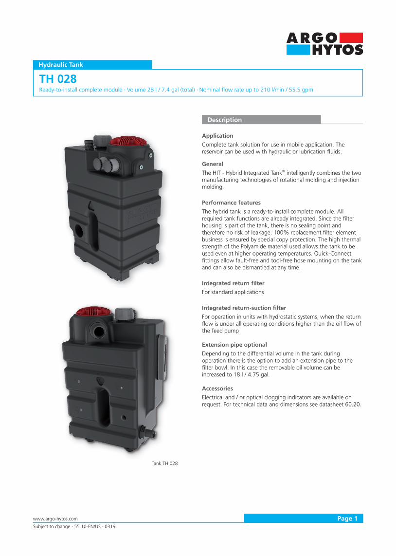
Application
Complete tank solution for use in mobile application. The reservoir can be used with hydraulic or lubrication fl uids.
General
The HIT - Hybrid Integrated Tank® intelligently combines the two manufacturing technologies of rotational molding and injection molding.
Performance features
The hybrid tank is a ready-to-install complete module. All required tank functions are already integrated. Since the fi lter housing is part of the tank, there is no sealing point and therefore no risk of leakage. 100% replacement fi lter element business is ensured by special copy protection. The high thermal strength of the Polyamide material used allows the tank to be used even at higher operating temperatures. Quick-Connect fi ttings allow fault-free and tool-free hose mounting on the tank and can also be dismantled at any time.
Integrated return fi lter
For standard applications
Integrated return-suction fi lter
For operation in units with hydrostatic systems, when the return fl ow is under all operating conditions higher than the oil fl ow of the feed pump
Extension pipe optional
Depending to the differential volume in the tank during operation there is the option to add an extension pipe to the fi lter bowl. In this case the removable oil volume can be increased to 18 l / 4.75 gal.
Accessories
Electrical and / or optical clogging indicators are available on request. For technical data and dimensions see datasheet 60.20.
Tank TH 028
Page 2 www.argo-hytos.com
Subject to change · 55.10-EN/US · 0319
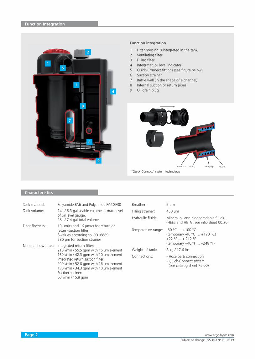
“Quick-Connect“ system technology
Function integration
1 Filter housing is integrated in the tank2 Ventilating fi lter3 Filling fi lter4 Integrated oil level indicator5 Quick-Connect fi ttings (see fi gure below)6 Suction strainer7 Baffl e wall (in the shape of a channel)8 Internal suction or return pipes9 Oil drain plug
1
7
8
3
2
4
6
9
5
O-ring Connection Nozzle Locking clip
Function Integration
Characteristics
Tank material: Polyamide PA6 and Polyamide PA6GF30
Tank volume: 24 l / 6.3 gal usable volume at max. level of oil level gauge. 28 l / 7.4 gal total volume.
Filter fi neness: 10 µm(c) and 16 µm(c) for return or return-suction fi lter; ß-values according to ISO16889280 µm for suction strainer
Nominal fl ow rates: Integrated return fi lter:210 l/min / 55.5 gpm with 16 µm element160 l/min / 42.3 gpm with 10 µm elementIntegrated return suction fi lter:200 l/min / 52.8 gpm with 16 µm element130 l/min / 34.3 gpm with 10 µm elementSuction strainer:60 l/min / 15.8 gpm
Breather: 2 µm
Filling strainer: 450 µm
Hydraulic fl uids: Mineral oil and biodegradable fl uids(HEES and HETG, see info-sheet 00.20)
Temperature range: -30 °C … +100 °C (temporary -40 °C … +120 °C)+22 °F ... + 212 °F(temporary +40 °F ... +248 °F)
Weight of tank: 8 kg / 17.6 lbs
Connections: - Hose barb connection- Quick-Connect system
(see catalog sheet 75.00)
Page 3www.argo-hytos.com
Subject to change · 55.10-EN/US · 0319
0123456789
10
0 200 400 600 800 1000
∆p
[b
ar] →
ν [mm²/s] →
D2
HIT RSF10
HIT RSF16
Pressure drop as a function of the kinematic viscosityat nominal flow
0
0,5
1
1,5
2
2,5
0 50 100 150 200 250 300
∆p
[bar
] →
Q [l/min] →
HIT RSF10
HIT RSF16
Gehäuse
Pressure drop as a function of the flow volumeat ν = 35 mm²/s
0123456789
10
0 200 400 600 800 1000∆
p [
ba
r] →
ν [mm²/s] →
D1
HIT RF10
HIT RF16
Pressure drop as a function of the kinematic viscosityat nominal flow
0
0,5
1
1,5
2
2,5
0 100 200 300 400
∆p
[bar
] →
Q [l/min] →
HIT RF10
HIT RF16
Gehäuse
Diagrams
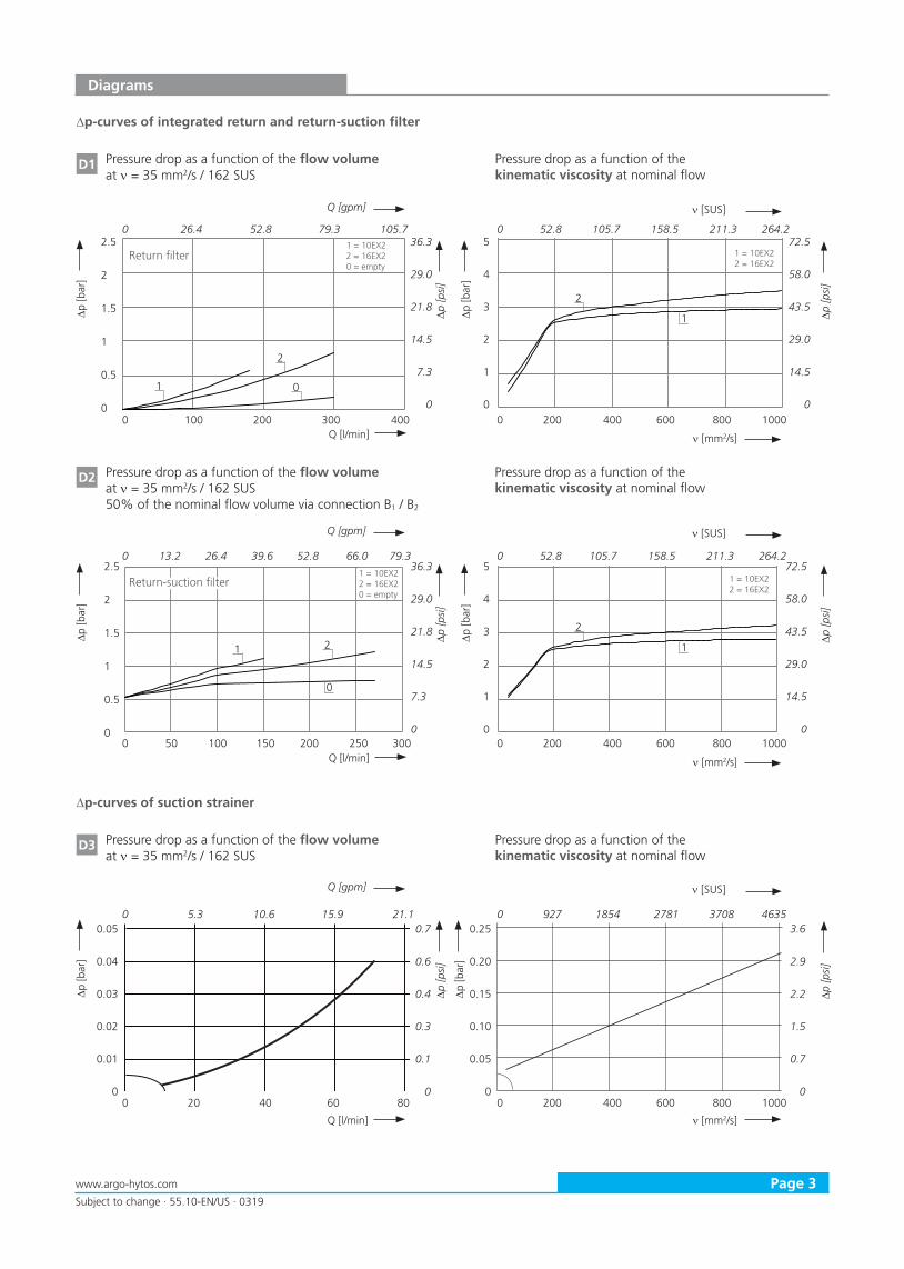
∆p-curves of integrated return and return-suction filter
D1 Pressure drop as a function of the flow volume at ν = 35 mm2/s / 162 SUS
Pressure drop as a function of the kinematic viscosity at nominal flow
D2 Pressure drop as a function of the flow volume at ν = 35 mm2/s / 162 SUS50% of the nominal flow volume via connection B1 / B2
Pressure drop as a function of the kinematic viscosity at nominal flow
2.5
2
1.5
1
0.5
0
ν [mm2/s]
∆p [b
ar]
Q [gpm]
∆p [p
si]
Q [l/min]
ν [SUS]
∆p [b
ar]
∆p [p
si]
0 100 200 300 400
0 26.4 52.8 79.3 105.7 36.3
29.0
21.8
14.5
7.3
0
5
4
3
2
1
00 200 400 600 800 1000
0 52.8 105.7 158.5 211.3 264.2
2.5
2
1.5
1
0.5
0
ν [mm2/s]
∆p [b
ar]
Q [gpm]
∆p [p
si]
Q [l/min]
ν [SUS]
∆p [b
ar]
∆p [p
si]
0 50 100 150 200 250 300
0 13.2 26.4 39.6 52.8 66.0 79.3 36.3
29.0
21.8
14.5
7.3
00 200 400 600 800 1000
0 52.8 105.7 158.5 211.3 264.2
Return filter
Return-suction filter
72.5
58.0
43.5
29.0
14.5
0
5
4
3
2
1
0
72.5
58.0
43.5
29.0
14.5
0
1
2
0
2
1
1 2
0
2
1
1 = 10EX22 = 16EX20 = empty
1 = 10EX22 = 16EX2
1 = 10EX22 = 16EX2
1 = 10EX22 = 16EX20 = empty
∆p-curves of suction strainer
D3 Pressure drop as a function of the flow volume at ν = 35 mm2/s / 162 SUS
Pressure drop as a function of the kinematic viscosity at nominal flow
0.05
0.04
0.03
0.02
0.01
0
∆p [b
ar]
∆p [p
si]
∆p [b
ar]
∆p [p
si]
0 20 40 60 80
0 5.3 10.6 15.9 21.1 0.7
0.6
0.4
0.3
0.1
00 200 400 600 800 1000
0 927 1854 2781 3708 4635 0.25
0.20
0.15
0.10
0.05
0
3.6
2.9
2.2
1.5
0.7
0
ν [mm2/s]
Q [gpm]
Q [l/min]
ν [SUS]
Page 4 www.argo-hytos.com
Subject to change · 55.10-EN/US · 0319
Diagrams
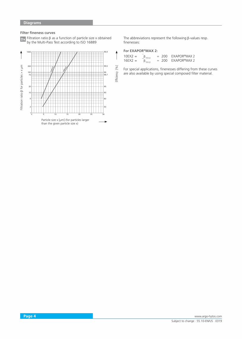
Filter fineness curves
Dx Filtration ratio β as a function of particle size x obtained by the Multi-Pass Test according to ISO 16889
The abbreviations represent the following β-values resp. finenesses:
For EXAPOR®MAX 2:
10EX2 = β10 (c) = 200 EXAPOR®MAX 216EX2 = β16 (c) = 200 EXAPOR®MAX 2
For special applications, finenesses differing from these curves are also available by using special composed filter material.
Filtr
atio
n ra
tio βfo
r pa
rtic
les
> x
µm
Effic
ienc
y [%
] Particle size x [µm] (for particles larger than the given particle size x)

Page 5www.argo-hytos.com
Subject to change · 55.10-EN/US · 0319
Ordering Code
Bypass valve and breather Code
2.5 bar / 36.3 psi bypass valveBreather with filling strainer OMO
Filter fineness Code
10 µm (10 µm) G1
16 µm (16 µm) I1
Tank type Code
Hydraulic tank28 l / 7.4 gal total volume TH028
Filter type and size Code
Return filter RF210
Return-suction filter RS200
Variant Code
With extension pipe 301
Without extension pipe empty
TH028 - - - OMO -
Filter fineness see diagram Dx Replacement filter element Part No.
10EX2 (10 µm) V9.1224-56
16EX2 (16 µm) V9.1224-58
Dimensions
1
A
2 3 4 5 6 7 8 9 10 11 12 13 14 15 16 17 18 19 20 21 22 23 24
B
C
D
E
F
G
H
I
J
K
L
M
N
O
P
1 2 3 4 5 6 7 8 9 10 11 12 13 14 15 16 17 18 19 20 21 22 23 24
A
B
C
D
E
F
G
H
I
J
K
L
M
N
O
P
= = =w x yRzmax 63 Rzmax 16 Rzmax 7
3
>3 >6 >30 >120 >400 >1000 >2000
6 30 120 400 1000 2000 4000
>0.5
tolerance 0.1 0.1 0.2 0.3 0.5 0.8 1.2 2.0
nominalsize
GENERAL TOLERANCES ISO 2768 - mK
Tolerances for linear measures
583
400
248
B
A A
A
C
285
155
80280
Anl
age
Index Description of change Date Editor
- - - -
- - - -
- - - -
- - - -
- - - -
Protection notice ISO 16016SAMPLE DRAWING
Scale 1:2 Weight kg8,44 The reproduction, distribution andutilization of this document aswell as the communication of itscontents to others without expressauthorization is prohibited.Offenders will be held liable forthe payment of damages.All rights reserved in the eventof the grant of a patent,utility model or design.
Material Dim. Rough.
- mm -Name
Tank vollst.Tank complete
Date 14.12.2018 Order key -Creator f.kollmannDate - Material no. 1000104270
Rev.A0Checker - 0
CAD produced drawing ISO 8015Substitute for
-Page
No manual modification allowed 1/1
M10
24l Max.
22l Min.
GÜLTIGE ARGO-HYTOS WERKNORMEN(VALID ARGO-HYTOS WORKS STANDARD)
2
B1*
Ports B1 and B2 on filter head closed with plugs in case of integrated return filter.
Replacement filter element
Tank assembly Order example:
TH028 - RS200 - I1 - OMO - 301
B2
B 3
A1
ConnectionsM12x1.5 for clogging indicator
Measurements ø A1 ø A2 ø B1, 2 ø B3
mm 48.9 37.0 37.0 32.0
inch 1.93 1.46 1.46 1.26For suitable Quick-Connect fittings see datasheet 75.00.
MAX 24 l /6.3 gal
MIN 22 l / 5.8 gal
Page 6 www.argo-hytos.com
Subject to change · 55.10-EN/US · 0319
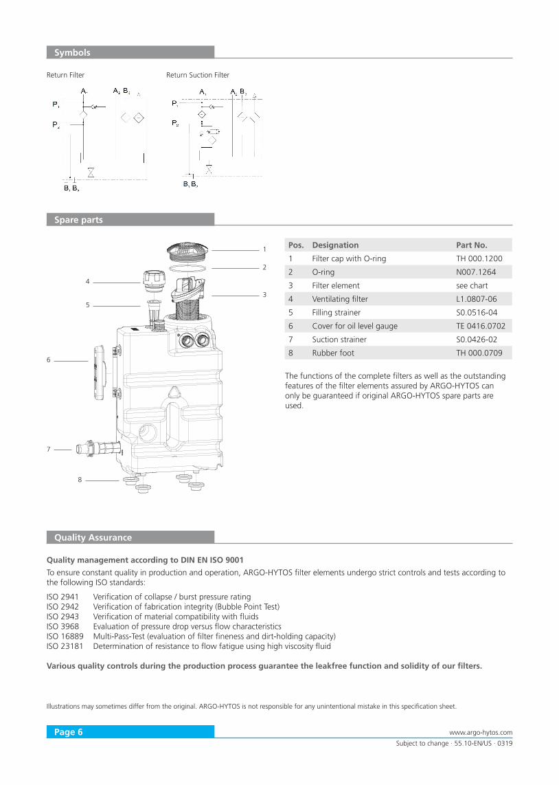
Spare parts
Pos. Designation Part No.
1 Filter cap with O-ring TH 000.1200
2 O-ring N007.1264
3 Filter element see chart
4 Ventilating filter L1.0807-06
5 Filling strainer S0.0516-04
6 Cover for oil level gauge TE 0416.0702
7 Suction strainer S0.0426-02
8 Rubber foot TH 000.0709
The functions of the complete filters as well as the outstanding features of the filter elements assured by ARGO-HYTOS can only be guaranteed if original ARGO-HYTOS spare parts are used.
Quality Assurance
Quality management according to DIN EN ISO 9001
To ensure constant quality in production and operation, ARGO-HYTOS filter elements undergo strict controls and tests according to the following ISO standards:
ISO 2941 Verification of collapse / burst pressure ratingISO 2942 Verification of fabrication integrity (Bubble Point Test)ISO 2943 Verification of material compatibility with fluidsISO 3968 Evaluation of pressure drop versus flow characteristicsISO 16889 Multi-Pass-Test (evaluation of filter fineness and dirt-holding capacity) ISO 23181 Determination of resistance to flow fatigue using high viscosity fluid
Various quality controls during the production process guarantee the leakfree function and solidity of our filters.
Illustrations may sometimes differ from the original. ARGO-HYTOS is not responsible for any unintentional mistake in this specification sheet.
1
A
2 3 4 5 6 7 8 9 10 11 12 13 14 15 16
B
C
D
E
F
G
H
I
J
K
L
1 2 3 4 5 6 7 8 9 10 11 12 13 14 15 16
A
B
C
D
E
F
G
H
I
J
K
L Anl
age
Index Description of change Date Editor
- - - -
- - - -
- - - -
- - - -
- - - -
Protection notice ISO 16016SAMPLE DRAWING
Scale 1:2 Weight
The reproduction, distribution andutilization of this document aswell as the communication of itscontents to others without expressauthorization is prohibited.Offenders will be held liable forthe payment of damages.All rights reserved in the eventof the grant of a patent,utility model or design.
Material Dim. Rough.
- mm -Name
Tank vollst.Tank complete
Date 11.03.2019 Order key -Creator f.kollmannDate - Material no. 41182500
Rev.A1Checker - 0
CAD produced drawing ISO 8015Substitute for
-Page
No manual modification allowed 1/1
1
2
3
4
5
6
7
8
Symbols
Return Filter Return Suction Filter