Embed Size (px)
Citation preview
Hydraulics Section I:Hydraulics Section I:BasicsBasics
Paul Trotta, P.E., Ph.D.Paul Trotta, P.E., Ph.D.Justin Ramsey, P.E.Justin Ramsey, P.E.
Chad Cooper Chad Cooper
University Curriculum Development University Curriculum Development for Decentralized Wastewater for Decentralized Wastewater
ManagementManagement

NDWRCDP DisclaimerNDWRCDP DisclaimerThis work was supported by the National Decentralized Water This work was supported by the National Decentralized Water Resources Capacity Development Project (NDWRCDP) with Resources Capacity Development Project (NDWRCDP) with
funding provided by the U.S. Environmental Protection Agency funding provided by the U.S. Environmental Protection Agency through a Cooperative Agreement (EPA No. CR827881through a Cooperative Agreement (EPA No. CR827881--0101--0) 0) with Washington University in St. Louis. These materials have with Washington University in St. Louis. These materials have
not been reviewed by the U.S. Environmental Protection not been reviewed by the U.S. Environmental Protection Agency. These materials have been reviewed by Agency. These materials have been reviewed by representatives of the NDWRCDP. The contents representatives of the NDWRCDP. The contents
of these materials do not necessarily reflect the views and of these materials do not necessarily reflect the views and policies of the NDWRCDP, Washington University, or the U.S. policies of the NDWRCDP, Washington University, or the U.S.
Environmental Protection Agency, nor does the mention of trade Environmental Protection Agency, nor does the mention of trade names or commercial products constitute their endorsement or names or commercial products constitute their endorsement or
recommendation for use.recommendation for use.

CIDWT/University DisclaimerCIDWT/University DisclaimerThese materials are the collective effort of individuals from These materials are the collective effort of individuals from
academic, regulatory, and private sectors of the academic, regulatory, and private sectors of the onsite/decentralized wastewater industry. These materials have onsite/decentralized wastewater industry. These materials have
been peerbeen peer--reviewed and represent the current state of reviewed and represent the current state of knowledge/science in this field. They were developed through a knowledge/science in this field. They were developed through a series of writing and review meetings with the goal of formulatiseries of writing and review meetings with the goal of formulating ng a consensus on the materials presented. These materials do not a consensus on the materials presented. These materials do not
necessarily reflect the views and policies of University of necessarily reflect the views and policies of University of Arkansas, and/or the Consortium of Institutes for Decentralized Arkansas, and/or the Consortium of Institutes for Decentralized
Wastewater Treatment (CIDWT). The mention of trade names or Wastewater Treatment (CIDWT). The mention of trade names or commercial products does not constitute an endorsement or commercial products does not constitute an endorsement or
recommendation for use from these individuals or entities, nor recommendation for use from these individuals or entities, nor does it constitute criticism for similar ones not mentioned.does it constitute criticism for similar ones not mentioned.

CitationCitation
Trotta, P.D., and J.O. Ramsey. 2005. Hydraulics I: Trotta, P.D., and J.O. Ramsey. 2005. Hydraulics I: Basics Basics -- PowerPoint Presentation. PowerPoint Presentation. inin (M.A. (M.A. Gross and N.E. Deal, eds.) University Gross and N.E. Deal, eds.) University Curriculum Development for Decentralized Curriculum Development for Decentralized Wastewater Management. National Wastewater Management. National Decentralized Water Resources Capacity Decentralized Water Resources Capacity Development Project. University of Arkansas, Development Project. University of Arkansas, Fayetteville, AR.Fayetteville, AR.

Section Objectives:Section Objectives:Use and convert typical hydraulic measurements of Use and convert typical hydraulic measurements of interest in the oninterest in the on--site arena.site arena.Make simple computations related to water; Flow rate, Make simple computations related to water; Flow rate, velocity and volume.velocity and volume.Compute the loss of head as water is pumped to other Compute the loss of head as water is pumped to other elevations and along pipes and fittings.elevations and along pipes and fittings.Compute the total head required to pump water from a Compute the total head required to pump water from a tank to a disposal field for a given flow rate.tank to a disposal field for a given flow rate.

Fundamental Properties of WaterFundamental Properties of Water
Density:Density:The ratio of the mass of The ratio of the mass of a given amount of a a given amount of a substance to the substance to the volume occupied. volume occupied. Relative Density Relative Density (Specific Gravity) (Specific Gravity) This is the ratio of the This is the ratio of the density of a substance density of a substance to that of water. to that of water.

Fundamental Properties of WaterFundamental Properties of Water
ViscosityViscositySurface TensionSurface TensionCompressibilityCompressibilityVapor PressureVapor Pressure

Fluid Fluid StaticsStatics::Pressure and its MeasurementPressure and its Measurement
Pressure Definition : Pressure = force per unit area

Air Pressure and Pressure from External Air Pressure and Pressure from External ForcesForces

Gage Versus AbsoluteGage Versus AbsoluteAbsolute Pressure: Total force per unit area.
Gauge Pressure: Difference in pressure from the atmospheric pressure

The ManometerThe ManometerThe manometer is a useful device for measuring The manometer is a useful device for measuring
gauge pressure in the field because all it takes is a gauge pressure in the field because all it takes is a clear tube and a measurementclear tube and a measurement
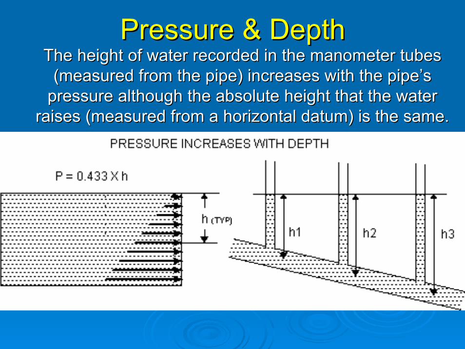
Pressure & DepthPressure & DepthThe height of water recorded in the manometer tubes The height of water recorded in the manometer tubes
(measured from the pipe) increases with the pipe(measured from the pipe) increases with the pipe’’s s pressure although the absolute height that the water pressure although the absolute height that the water
raises (measured from a horizontal datum) is the same.raises (measured from a horizontal datum) is the same.

BuoyancyBuoyancyBuoyancy = The net upward force exerted on Buoyancy = The net upward force exerted on an object by the surrounding body of water.an object by the surrounding body of water.

Consider a septic tank set in an area, which Consider a septic tank set in an area, which is subject to seasonal high ground wateris subject to seasonal high ground water
The water surrounds the tank and even though the tank is The water surrounds the tank and even though the tank is not in a large body of water the surrounding water exerts the not in a large body of water the surrounding water exerts the
same pressure it would if the tank were submerged to the same pressure it would if the tank were submerged to the same depth in a large tank. same depth in a large tank.

Simplified ViewSimplified View
Wt + Ww + Ws > B the tank will not float
Wt + Ww + Ws < B the tank will float.

ContinuityContinuity
In Checkbook:Deposits – Withdrawals = Change in Balance
In hydraulics:Total Inflow – Total Outflow = Change In Volume
Or,Final Volume = Initial Volume + Total Inflow – Total Outflow

ContinuityContinuity
Closed SystemsClosed Systems
AndAnd
Open SystemsOpen Systems

Continuity In Closed SystemsContinuity In Closed SystemsIn a closed and filled system where there is no place for either additional storage or release of water continuity simplifies to:
Deposits – Withdrawals = 0 Or,
Deposits = Withdrawals

Continuity In Open SystemsContinuity In Open SystemsExample #1:
A 200 gallon tank initially holds 100 gallons. 50 gallons are added and 25 gallons are removed.
At the end of the process 125 gallons remain in the tank
Using flow rates make things a bit more complicated but not much.
Inflow (rate) x Inflow time - Outflow (rate) x Outflow time = Change in Volume

Example #2Example #2A 200gallon tank initially holds 100 gallons. 10 gallons/minute are added for 10 minutes and 25 gallons/minute are removed for 2 minutes. At the end of the process 150 gallons remain in the tankFinal Volume = 100 gallons + 10 g/minute x 10 m - 25 g/minute x 2 m = 150 gallons

Example Example #3
A 1000 gallon pump tank has outside dimensions of 8 feet long x 6 feet wide x 5 feet deep. The concrete used is 0.5 feet thick (all around).
Initially there is 2 feet of water in the tank. 300 gallons are added from household use and the pump goes on for 200 seconds, pumping 50 gallons per minute. What is the final water surface elevation in the tank?
#3

Answer:Answer:First compute the outflow in gallons:50 gpm x 200 seconds/ 60 seconds/min = 166.6 gal
Next compute the total change in volume:300 gal(inflow) - 166.6 gal(outflow) = 133.4 gal (change)
Next convert gallons to cubic feet.133.4 gal/7.48 gal/ ft3 = 17.83 ft3
The inside dimensions of the tank are obtained by subtracting the wall thickness (twice – once for each side) 8 ft – 0.5 ft – 0.5 ft = 7 ft and6 ft – 0.5 ft –0.5 ft = 5 ft
Now divide the change in volume by the inside area.17.83 ft3 / (7 ft x 5 ft) = 0.51ft
Finally, convert the change in elevation to inches.0.51 ft x 12 in/ft = 6.11 in (which is the change in tank depth)Since more came in than went out the final tank elevation 2.51 ft or 2 ft + 6.11 inches (or 30.11”) (which is the final tank depth—The answer !)

Continuity in a Constructed Continuity in a Constructed WetlandWetland
INFLOW – OUTFLOW = CHANGE IN INTERNAL VOLUME STORED IN A CONSTRUCTED WETLAND (SEABLOOM)

Continuity for Water in MotionContinuity for Water in Motion
V1 x A1 = V2 x A2 = Q
V1/V2 = A2/A1 = (R2/R1) 2 = (D2/D1) 2
Example:
D1 = 1 inches D2 = 2 inches and Q = 500 gpm
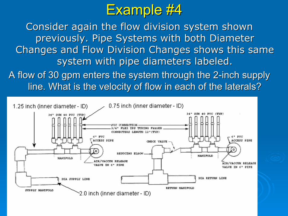
Example #4Example #4Consider again the flow division system shown Consider again the flow division system shown
previously. Pipe Systems with both Diameter previously. Pipe Systems with both Diameter Changes and Flow Division Changes shows this same Changes and Flow Division Changes shows this same
system with pipe diameters labeled. system with pipe diameters labeled. A flow of 30 gpm enters the system through the 2A flow of 30 gpm enters the system through the 2--inch supply inch supply
line. What is the velocity of flow in each of the laterals?line. What is the velocity of flow in each of the laterals?