Embed Size (px)
Citation preview
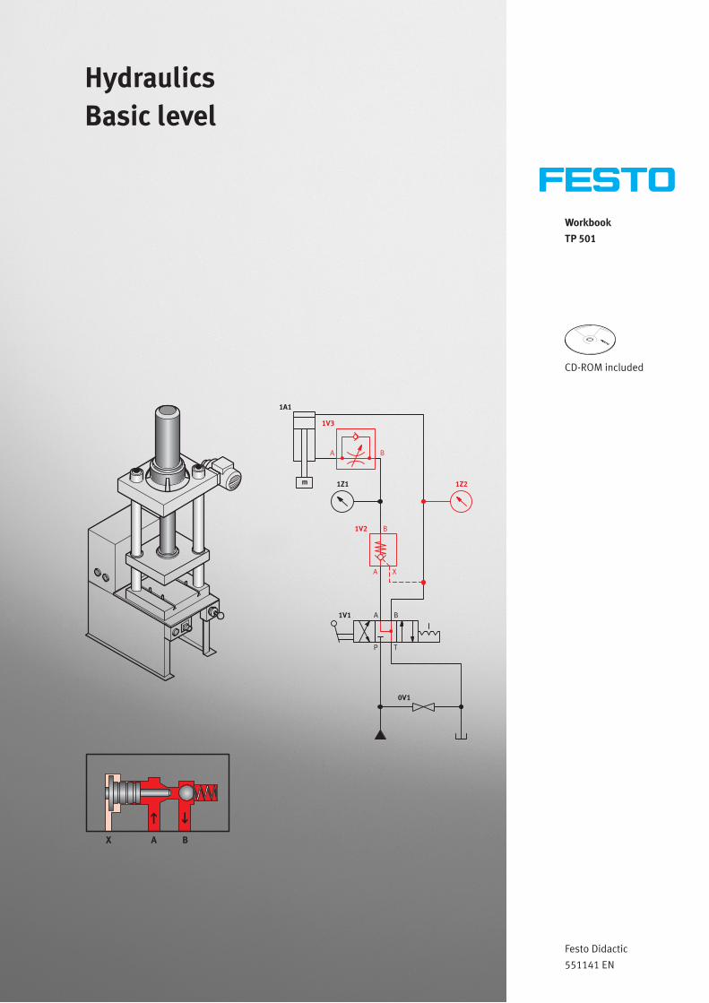
WorkbookTP 501
CD-ROM included
Festo Didactic
551141 EN
HydraulicsBasic level
1Z21Z1
1A1
m
0V1
B
XA
1V2
A1V1 B
TP
BA
1V3
BAX
Order No.: 551141
Edition: 09/2011
Authors: Renate Aheimer, Frank Ebel, Annabella Zimmermann
Graphics: Doris Schwarzenberger
Layout: 09/2011, Frank Ebel
© Festo Didactic GmbH & Co. KG, 73770 Denkendorf, Germany, 2011
Internet: www.festo-didactic.com
E-mail: [email protected]
The copying, distribution and utilization of this document as well as the communication of its contents to
others without expressed authorization is prohibited. Offenders will be held liable for the payment of
damages. All rights reserved, in particular the right to carry out patent, utility model or ornamental design
registration.
© Festo Didactic GmbH & Co. KG 551141 III
Table of contents
Use for intended purpose __________________________________________________________________ V
Preface ______________________________________________________________________________ VI
Introduction ____________________________________________________________________________ VIII
Work instructions and safety precautions _____________________________________________________ IX
Training package for hydraulics (TP 500) _____________________________________________________ XI
Learning objectives, hydraulics, basic level (TP 501) ____________________________________________ XII
Allocation of learning objectives to exercises __________________________________________________ XIV
Equipment set _________________________________________________________________________ XVII
Allocation of components to exercises _______________________________________________________ XIX
Notes for the teacher/trainer _______________________________________________________________ XX
Structure of the exercises _________________________________________________________________ XXI
Component designations _________________________________________________________________ XXII
CD-ROM contents _______________________________________________________________________ XXII
Exercises and solutions
Exercise 1: Setting up a hydraulic workstation _________________________________________________ 3
Exercise 2: Commissioning a two-column hydraulic press ______________________________________ 13
Exercise 3: Measuring the characteristic pump curve __________________________________________ 21
Exercise 4: Measuring the opening characteristics of a pressure-relief valve _______________________ 33
Exercise 5: Unloading a paper machine _____________________________________________________ 41
Exercise 6: Opening a hardening furnace ____________________________________________________ 51
Exercise 7: Opening and closing a boiler door ________________________________________________ 59
Exercise 8: Dimensioning an assembly device ________________________________________________ 69
Exercise 9: Sorting shipping crates_________________________________________________________ 73
Exercise 10: Measuring the characteristic curve of a flow control valve_____________________________ 83
Exercise 11: Adjusting stroke speed at a hydraulic lift __________________________________________ 93
Exercise 12: Optimising an embossing machine ______________________________________________ 103
Exercise 13: Matching retracting and advancing speed ________________________________________ 115
Exercise 14: Securing a cylinder against unintentional retraction ________________________________ 123
Exercise 15: Correcting misalignment of a conveyor belt _______________________________________ 133
Exercise 16: Counter-pressure for closing a bulkhead door _____________________________________ 139
Exercise 17: Loading and unloading buckets _________________________________________________ 145
Table of contents
IV © Festo Didactic GmbH & Co. KG 551141
Exercises and worksheets
Exercise 1: Setting up a hydraulic workstation _________________________________________________ 3
Exercise 2: Commissioning a two-column hydraulic press ______________________________________ 13
Exercise 3: Measuring the characteristic pump curve __________________________________________ 21
Exercise 4: Measuring the opening characteristics of a pressure-relief valve _______________________ 33
Exercise 5: Unloading a paper machine _____________________________________________________ 41
Exercise 6: Opening a hardening furnace ____________________________________________________ 51
Exercise 7: Opening and closing a boiler door ________________________________________________ 59
Exercise 8: Dimensioning an assembly device ________________________________________________ 69
Exercise 9: Sorting shipping crates_________________________________________________________ 73
Exercise 10: Measuring the characteristic curve of a flow control valve_____________________________ 83
Exercise 11: Adjusting stroke speed at a hydraulic lift __________________________________________ 93
Exercise 12: Optimising an embossing machine ______________________________________________ 103
Exercise 13: Matching retracting and advancing speed ________________________________________ 115
Exercise 14: Securing a cylinder against unintentional retraction ________________________________ 123
Exercise 15: Correcting misalignment of a conveyor belt _______________________________________ 133
Exercise 16: Counter-pressure for closing a bulkhead door _____________________________________ 139
Exercise 17: Loading and unloading buckets _________________________________________________ 145
© Festo Didactic GmbH & Co. KG 551141 V
Use for intended purpose
The training package for basic level hydraulics may only be used:
• For its intended purpose in teaching and training applications
• When its safety functions are in flawless condition
The components included in the training package are designed in accordance with the latest technology, as
well as recognised safety rules. However, life and limb of the user and third parties may be endangered, and
the components may be impaired, if they are used improperly.
The training system from Festo Didactic has been developed and manufactured exclusively for training and
vocational education in the fields of automation and technology. The respective training companies and/or
trainers must ensure that all trainees observe the safety precautions which are described in this workbook.
Festo Didactic hereby excludes any and all liability for damages suffered by trainees, the training company
and/or any third parties, which occur during use of the equipment set in situations which serve any purpose
other than training and/or vocational education, unless such damages have been caused by Festo Didactic
due to malicious intent or gross negligence.
VI © Festo Didactic GmbH & Co. KG 551141
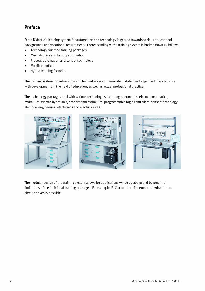
Preface
Festo Didactic’s learning system for automation and technology is geared towards various educational
backgrounds and vocational requirements. Correspondingly, the training system is broken down as follows:
• Technology oriented training packages
• Mechatronics and factory automation
• Process automation and control technology
• Mobile robotics
• Hybrid learning factories
The training system for automation and technology is continuously updated and expanded in accordance
with developments in the field of education, as well as actual professional practice.
The technology packages deal with various technologies including pneumatics, electro-pneumatics,
hydraulics, electro-hydraulics, proportional hydraulics, programmable logic controllers, sensor technology,
electrical engineering, electronics and electric drives.
The modular design of the training system allows for applications which go above and beyond the
limitations of the individual training packages. For example, PLC actuation of pneumatic, hydraulic and
electric drives is possible.
© Festo Didactic GmbH & Co. KG 551141 VII
All training packages are comprised of the following elements:
• Hardware
• Media
• Seminars
Hardware Hardware included in the training packages consists of industrial components and systems that are
specially designed for training purposes. The selection and design of the components encompassed by the
training packages are especially well matched to the projects included in the accompanying media.
Media The media provided for the individual groups of topics are allocated to the teachware and software
categories. The practically oriented teachware includes:
• Technical books and textbooks (standard works for imparting basic knowledge)
• Workbooks (practical exercises with supplementary instructions and sample solutions)
• Lexicons, manuals and technical books (which provide technical information on groups of topics for
further exploration)
• Transparency sets and videos (for easy-to-follow, dynamic instruction)
• Posters (for clear-cut representation of facts)
From the software category, programmes are made available for the following applications:
• Digital training programmes (didactically and medially prepared learning content)
• Simulation software
• Visualisation software
• Software for measurement data acquisition
• Project engineering and design engineering software
• Programming software for programmable logic controllers
The teaching and learning media are available in several languages. They are intended for use in classroom
instruction, but are also suitable for self-study.
Seminars Comprehensive seminar offerings covering the contents of the training packages round out the programme
for training and vocational education.
Do you have suggestions or criticism regarding this manual?
If so, send us an e-mail at [email protected].
The authors and Festo Didactic look forward to your feedback.
VIII © Festo Didactic GmbH & Co. KG 551141
Introduction
This workbook is part of the training system for automation technology from Festo Didactic GmbH & Co. KG.
The system provides a solid basis for practice oriented training and vocational education. Training packages
TP 501 and TP 502 include strictly hydraulic controllers only.
The TP 501 basic level is suitable for fundamental training in the field of hydraulic control technology.
Knowledge regarding the fundamentals of hydraulics, as well as the function and use of hydraulic
components, is imparted. Simple hydraulic controllers can be set up with the equipment set. The TP 502
advanced level is targeted at vocational training in the field of hydraulic control technology. More advanced
hydraulic circuits can be set up with this equipment set.
This workbook imparts knowledge regarding the physical relationships which prevail in the field of
hydraulics, and its most important basic circuits. Topics covered by the exercises include:
• Recording the characteristic curves of individual components
• Comparing usage of various components
• Setting up various basic circuits
• Applying basic hydraulic equations
Technical prerequisites for setting up the controllers include:
• A Learnline or Learntop-S workstation equipped with a Festo Didactic slotted profile plate. The slotted
profile plate has 14 parallel T-slots at 50 mm intervals.
• A hydraulic power unit (operating voltage: 230 V, 50 Hz, operating pressure: 6 MPa (60 bar),
volumetric flow rate: 2 l/min.)
• A power pack with short-circuit protection (input: 230 V, 50 Hz, output: 24 V, max. 5 A) for supplying
power to the flow sensor
• Laboratory safety cables
You will only need components included in equipment set TP 501 in order to complete the 17 exercises. The
theoretical fundamentals for understanding these exercises are included in the textbook:
• Hydraulics, basic level
Data sheets for the individual components are also available (cylinders, valves etc.).
© Festo Didactic GmbH & Co. KG 551141 IX
Work and safety instructions
General • Trainees should only work with the circuits under the supervision of a trainer.
• Operate electrical devices (e.g. power supply units, compressors, hydraulic power units) only in
laboratories that are equipped with a Residual Current Device (RCD).
• Observe specifications included in the technical data for the individual components, and in particular all
safety instructions!
• Faults which may impair safety must not be generated in the training environment and must be
eliminated immediately.
• Wear your personal protective equipment (safety goggles, safety shoes) if you are working on the
circuits.
Mechanical setup • Only reach into the setup when it is at a complete standstill.
• Mount all of the components securely onto the slotted profile plate.
• Limit switches may not be actuated frontally.
• Danger of injury during troubleshooting!
Use a tool to actuate the limit switches, for example a screwdriver.
• Set all components up so that activation of switches and disconnectors is not made difficult.
• Adhere to the instructions regarding positioning of the components.
• Always set up cylinders together with the appropriate cover.
Electrical specifications • Only use extra low voltages: max. 24 V DC.
• Electrical connections may only be established and interrupted in the absence of voltage!
• Only use connecting cables with safety plugs for electrical connections.
• Pull the plug only when disconnecting connector cables – never pull the cable.
Hydraulics • Limit system pressure to 6 MPa (60 bar).
Maximum permissible pressure for all devices included in the training package is 12 MPa (120 bar).
• Danger of injury from oil temperatures > 50 ° C!
Hydraulic oil with a temperature > 50 ° C can cause burns or scalding.
• Danger of injury when switching on the hydraulic power unit!
Cylinders may advance and retract automatically.
• All valves, devices and hose lines are equipped with self-sealing quick-connect couplings.
X © Festo Didactic GmbH & Co. KG 551141
• Connecting hose lines
– Never connect or disconnect hose lines when the hydraulic power unit is running,
or while under pressure!
Couplings must be connected in the unpressurised state.
– Set the coupling socket squarely onto the coupling nipple!
The coupling socket and the coupling nipple must not be fitted askew.
• Setting up hydraulic circuits
– The hydraulic power unit and the electrical power pack must be switched off when assembling the
circuit.
– Before commissioning, make sure that all tank lines have been connected and that all couplings
have been securely fitted.
• Commissioning
– Cylinders may only be commissioned with their covers in place.
– Switch on the electrical power pack first, and then the hydraulic power unit.
• Dismantling hydraulic circuits
– Assure that pressure has been relived before dismantling the circuit.
– Switch off the hydraulic power unit first, and then the electrical power pack.
• If connections are decoupled while under pressure, pressure is trapped in the device by the non-return
valve in the coupling. This pressure can be vented with the pressure relief unit.
Mounting technology The mounting boards for the components are equipped with mounting variant A, B or C:
• Variant A, snap-in system
Lightweight components that are not load-bearing (e.g. directional control valves and sensors). Simply
clip the components into the slots on the slotted profile plate. Release the components by turning the
blue lever.
• Variant B, bolt system
Components with medium load capacity (e.g. hydraulic or pneumatic cylinder). These components are
clamped onto the profile plate using T-head bolts. The blue, knurled nut is used for clamping and
loosening.
• Variant C, screw system
For components with high load capacity and components which are seldom removed from the profile
plate (for example on-off valve with filter-regulator). The devices are secured with socket head screws
and T-head bolts.
Required accessories A digital multimeter is required in order to evaluate exercises which make use of the flow sensor.
The output voltage of the flow sensor is measured with the multimeter.
You will need a stopwatch in order to measure hydraulic cylinder retracting and advancing times.
© Festo Didactic GmbH & Co. KG 551141 XI
Training package for hydraulics (TP 500)
The TP 500 training package consists of a multitude of individual training materials and seminars. The
subject matter of this package is strictly hydraulic controllers. Individual components from training package
TP 500 may also be included in other packages.
Important TP 500 components • Permanent workstation with Festo Didactic slotted profile plate
• Equipment sets or individual components (e.g. cylinders, valves and pressure gauges)
• Complete laboratory setups
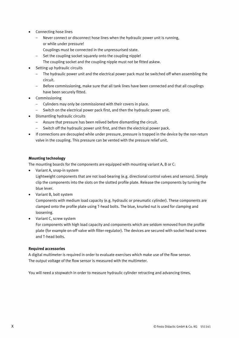
Media The teachware for the TP 500 training package consists of a textbook and a workbook. The textbook imparts
basic physical and technical knowledge regarding hydraulics. The workbook includes exercise sheets for
each exercise, the solutions to each individual worksheet and a CD-ROM. A set of ready-to-use exercise
sheets and worksheets is included in each workbook for all of the exercises.
Data sheets for the hardware components are made available along with the equipment set.
Media
Textbook Hydraulics, basic level
Workbook Hydraulics, basic level (TP 501)
Hydraulics, advanced level (TP 502)
Set of transparencies Fundamentals of hydraulics
Simulation programme FluidSIM® Hydraulic
Digital training programme WBT hydraulics
Overview of media for the TP 500 training package
Available software for use in combination with training package TP 500 includes FluidSIM® H and the
Hydraulics digital training programme. FluidSIM® H supports preparation of the lessons. Hydraulic
controllers can be set up and simulated. The Hydraulics digital training programme imparts knowledge
regarding the fundamentals of hydraulic controllers. With the help of examples based on actual industrial
practice, the learner works through the basic principles of hydraulics and becomes familiar with components
used in hydraulic systems.
The media are offered in several languages. You will find further training materials in our catalogues and on
the Internet.
XII © Festo Didactic GmbH & Co. KG 551141
Learning objectives, hydraulics, basic level (TP 501)
Components • Become familiar with the setup and function of a hydraulic pump.
• Become familiar with the most important characteristics of a hydraulic pump.
• Be able to explain how pressure occurs in hydraulic controllers.
• Become familiar with the relationship between pump delivery rate and operating pressure.
• Become familiar with the various types and possible uses of pressure-relief valves.
• Become familiar with the setup and function of a pressure-relief valve.
• Become familiar with the setup and function of a single-acting cylinder.
• Become familiar with the setup and function of a double-acting cylinder.
• Become familiar with the setup and function of a 2/2-way valve.
• Become familiar with the setup and function of a 3/2-way valve.
• Become familiar with the setup and function of a 4/2-way valve.
• Become familiar with the setup and function of 4/3-way valves.
• Be able to evaluate the influences of the various mid-position variants of 4/3-way valves.
• Become familiar with the setup and function of a non-return valve.
• Become familiar with the setup and function of a one-way flow control valve.
• Become familiar with the setup and function of a piloted non-return valve.
• Become familiar with the setup and function of a flow control valve.
Circuits • Be able to safely commission hydraulic controllers.
• Be able to control a single-acting cylinder.
• Be able to explain the differences between supply and exhaust flow control.
• Be able to compare circuits with flow control valves in the inlet and the outlet.
• Be able to use a flow control valve to adjust the speed of a drive.
• Be able to name various applications for flow control valves.
• Be able to explain the difference between flow control valves and one-way flow control valves used in
the application.
• Become familiar with the setup and mode of operation of a bypass circuit.
• Be able to explain the influence of the piston’s surface area on pressure, force and travel time.
• Be able to make proper use of piloted non-return valves.
• Become familiar with hydraulic restraint of a double-acting cylinder.
• Be able to compare circuits with and without counter pressure.
• Be able to explain the differences between counter-pressure circuits located between the one-way flow
control valve and the pressure-relief valve.
• Be able to operate double-acting cylinders with changing loads.
© Festo Didactic GmbH & Co. KG 551141 XIII
Measurements and calculations • Learn to record and interpret the characteristic curve of a hydraulic pump.
• Learn to measure the volumetric flow rate in hydraulic controllers.
• Learn to record the characteristic curve of a pressure-relief valve.
• Learn to record the characteristic curve of a flow control valve.
• Learn to ascertain times, pressures and forces during the advancing and retracting strokes of a single-
acting cylinder.
• Learn to ascertain times, pressures and forces during the advancing and retracting strokes of a double-
acting cylinder.
• Learn to calculate piston advancing times.
• Learn to calculate the balance of activities when using 4/3-way valves with different mid-positions.
XIV © Festo Didactic GmbH & Co. KG 551141
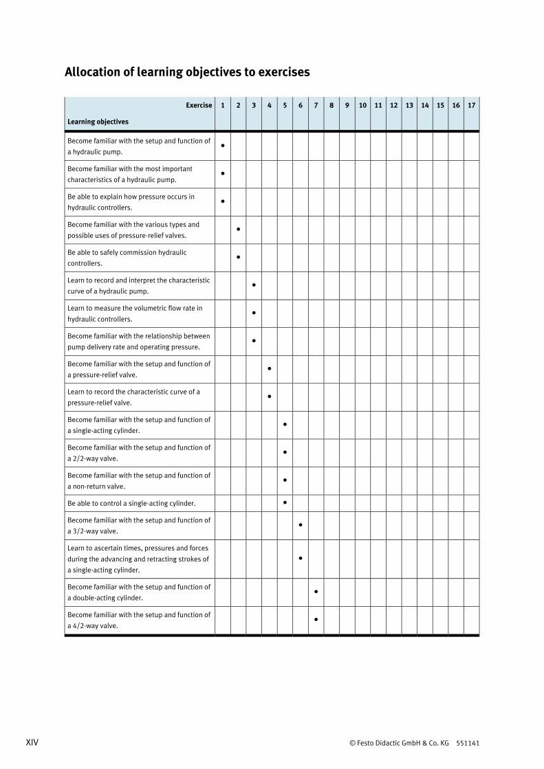
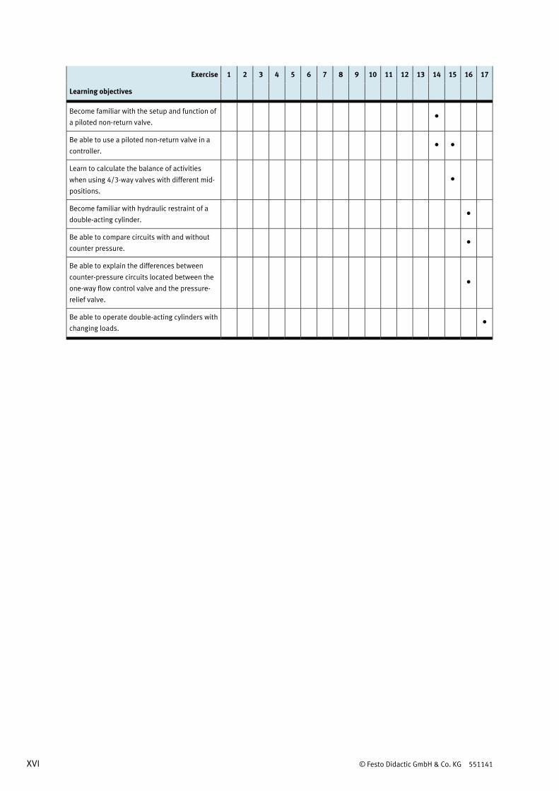
Allocation of learning objectives to exercises
Exercise 1 2 3 4 5 6 7 8 9 10 11 12 13 14 15 16 17
Learning objectives
Become familiar with the setup and function of
a hydraulic pump. •
Become familiar with the most important
characteristics of a hydraulic pump. •
Be able to explain how pressure occurs in
hydraulic controllers. •
Become familiar with the various types and
possible uses of pressure-relief valves. •
Be able to safely commission hydraulic
controllers. •
Learn to record and interpret the characteristic
curve of a hydraulic pump. •
Learn to measure the volumetric flow rate in
hydraulic controllers. •
Become familiar with the relationship between
pump delivery rate and operating pressure. •
Become familiar with the setup and function of
a pressure-relief valve. •
Learn to record the characteristic curve of a
pressure-relief valve. •
Become familiar with the setup and function of
a single-acting cylinder. •
Become familiar with the setup and function of
a 2/2-way valve. •
Become familiar with the setup and function of
a non-return valve. •
Be able to control a single-acting cylinder. •
Become familiar with the setup and function of
a 3/2-way valve. •
Learn to ascertain times, pressures and forces
during the advancing and retracting strokes of
a single-acting cylinder.
•
Become familiar with the setup and function of
a double-acting cylinder. •
Become familiar with the setup and function of
a 4/2-way valve. •
© Festo Didactic GmbH & Co. KG 551141 XV
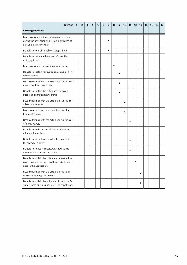
Exercise 1 2 3 4 5 6 7 8 9 10 11 12 13 14 15 16 17
Learning objectives
Learn to calculate times, pressures and forces
during the advancing and retracting strokes of
a double-acting cylinder.
•
Be able to control a double-acting cylinder. •
Be able to calculate the forces of a double-
acting cylinder. •
Learn to calculate piston advancing times. •
Be able to explain various applications for flow
control valves. •
Become familiar with the setup and function of
a one-way flow control valve. •
Be able to explain the differences between
supply and exhaust flow control. •
Become familiar with the setup and function of
a flow control valve. •
Learn to record the characteristic curve of a
flow control valve. •
Become familiar with the setup and function of
4/3-way valves. •
Be able to evaluate the influences of various
mid-position variants. •
Be able to use a flow control valve to adjust
the speed of a drive. •
Be able to compare circuits with flow control
valves in the inlet and the outlet. •
Be able to explain the difference between flow
control valves and one-way flow control valves
used in the application.
•
Become familiar with the setup and mode of
operation of a bypass circuit. •
Be able to explain the influence of the piston’s
surface area on pressure, force and travel time. •
XVI © Festo Didactic GmbH & Co. KG 551141
Exercise 1 2 3 4 5 6 7 8 9 10 11 12 13 14 15 16 17
Learning objectives
Become familiar with the setup and function of
a piloted non-return valve. •
Be able to use a piloted non-return valve in a
controller. • •
Learn to calculate the balance of activities
when using 4/3-way valves with different mid-
positions.
•
Become familiar with hydraulic restraint of a
double-acting cylinder. •
Be able to compare circuits with and without
counter pressure. •
Be able to explain the differences between
counter-pressure circuits located between the
one-way flow control valve and the pressure-
relief valve.
•
Be able to operate double-acting cylinders with
changing loads. •
© Festo Didactic GmbH & Co. KG 551141 XVII
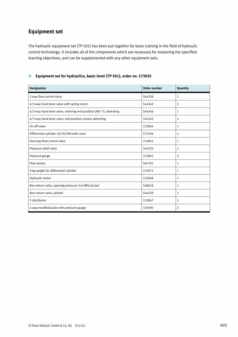
Equipment set
The hydraulic equipment set (TP 501) has been put together for basic training in the field of hydraulic
control technology. It includes all of the components which are necessary for mastering the specified
learning objectives, and can be supplemented with any other equipment sets.
Equipment set for hydraulics, basic level (TP 501), order no. 573035
Designation Order number Quantity
2-way flow control valve 544338 1
4/2-way hand lever valve with spring return 544342 1
4/3-way hand lever valve, relieving mid-position (AB > T), detenting 544344 1
4/3-way hand lever valve, mid-position closed, detenting 544343 1
On-off valve 152844 1
Differential cylinder 16/10/200 with cover 572746 1
One-way flow control valve 152843 1
Pressure-relief valve 544335 1
Pressure gauge 152841 3
Flow sensor 567191 1
9 kg weight for differential cylinder 152972 1
Hydraulic motor 152858 1
Non-return valve, opening pressure: 0.6 MPa (6 bar) 548618 1
Non-return valve, piloted 544339 1
T-distributor 152847 1
4-way manifold plate with pressure gauge 159395 2
XVIII © Festo Didactic GmbH & Co. KG 551141
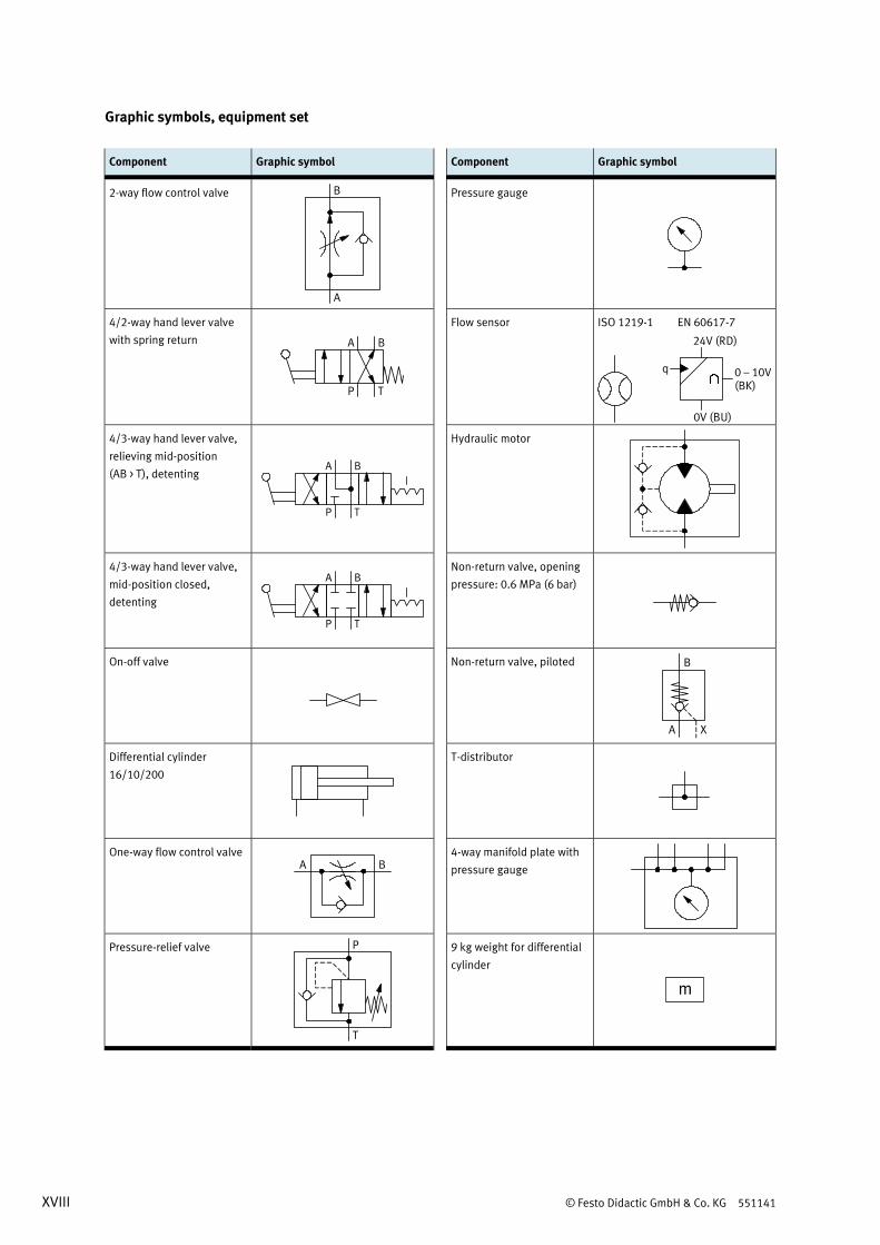
Graphic symbols, equipment set
Component Graphic symbol Component Graphic symbol
2-way flow control valve
Pressure gauge
4/2-way hand lever valve
with spring return BA
TP
Flow sensor ISO 1219-1 EN 60617-7
0V (BU)
q
24V (RD)
0 – 10V(BK)
4/3-way hand lever valve,
relieving mid-position
(AB > T), detenting BA
TP
Hydraulic motor
4/3-way hand lever valve,
mid-position closed,
detenting
BA
TP
Non-return valve, opening
pressure: 0.6 MPa (6 bar)
On-off valve
Non-return valve, piloted
Differential cylinder
16/10/200
T-distributor
One-way flow control valve A B
4-way manifold plate with
pressure gauge
Pressure-relief valve P
T
9 kg weight for differential
cylinder
m
© Festo Didactic GmbH & Co. KG 551141 XIX
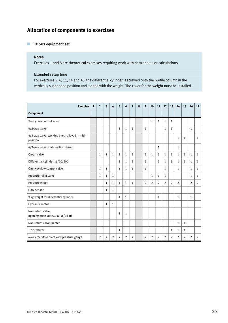
Allocation of components to exercises
TP 501 equipment set
Notes
Exercises 1 and 8 are theoretical exercises requiring work with data sheets or calculations.
Extended setup time
For exercises 5, 6, 11, 14 and 16, the differential cylinder is screwed onto the profile column in the
vertically suspended position and loaded with the weight. The cover for the weight must be installed.
Exercise 1 2 3 4 5 6 7 8 9 10 11 12 13 14 15 16 17
Component
2-way flow control valve 1 1 1 1
4/2-way valve 1 1 1 1 1 1 1
4/3-way valve, working lines relieved in mid-
position 1 1 1
4/3-way valve, mid-position closed 1 1
On-off valve 1 1 1 1 1 1 1 1 1 1 1 1 1 1 1
Differential cylinder 16/10/200 1 1 1 1 1 1 1 1 1 1 1
One-way flow control valve 1 1 1 1 1 1 1 1 1 1
Pressure-relief valve 1 1 1 1 1 1 1 1
Pressure gauge 1 1 1 1 1 2 2 2 2 2 2 2 2
Flow sensor 1 1
9 kg weight for differential cylinder 1 1 1 1 1
Hydraulic motor 1 1
Non-return valve,
opening pressure: 0.6 MPa (6 bar) 1 1
Non-return valve, piloted 1 1
T-distributor 1 1 1 1
4-way manifold plate with pressure gauge 2 2 2 2 2 2 2 2 2 2 2 2 2 2 2
XX © Festo Didactic GmbH & Co. KG 551141
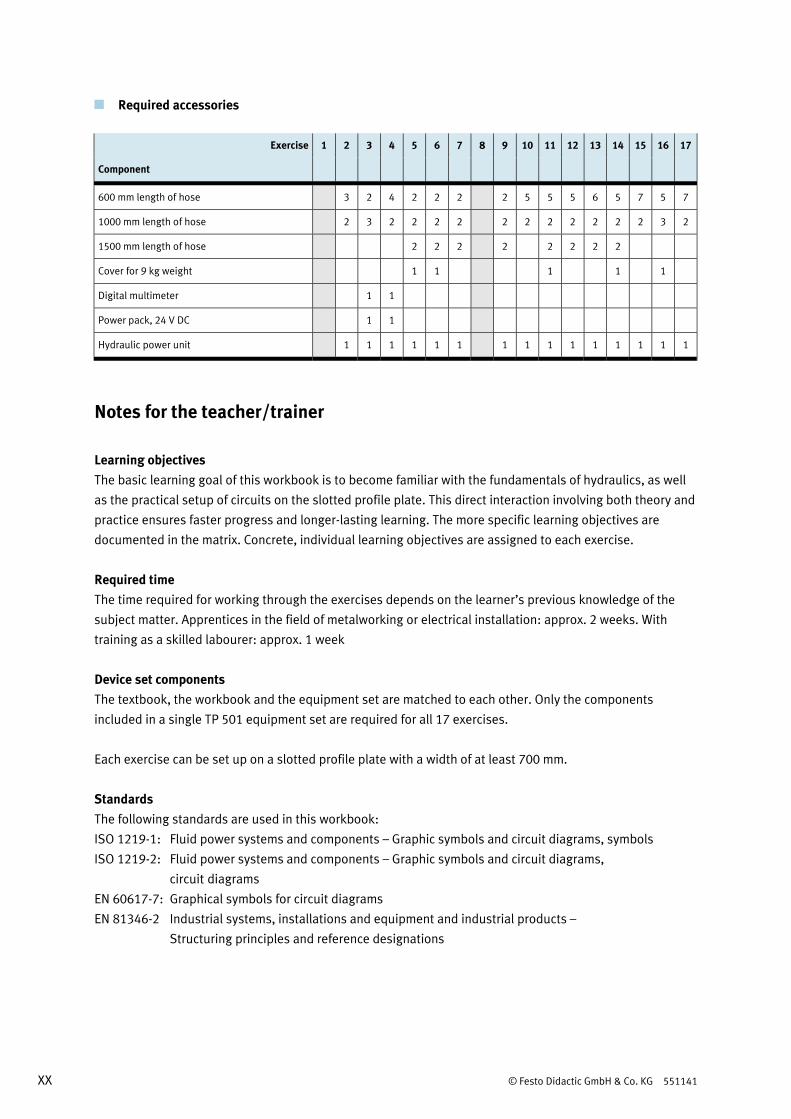
Required accessories
Exercise 1 2 3 4 5 6 7 8 9 10 11 12 13 14 15 16 17
Component
600 mm length of hose 3 2 4 2 2 2 2 5 5 5 6 5 7 5 7
1000 mm length of hose 2 3 2 2 2 2 2 2 2 2 2 2 2 3 2
1500 mm length of hose 2 2 2 2 2 2 2 2
Cover for 9 kg weight 1 1 1 1 1
Digital multimeter 1 1
Power pack, 24 V DC 1 1
Hydraulic power unit 1 1 1 1 1 1 1 1 1 1 1 1 1 1 1
Notes for the teacher/trainer
Learning objectives The basic learning goal of this workbook is to become familiar with the fundamentals of hydraulics, as well
as the practical setup of circuits on the slotted profile plate. This direct interaction involving both theory and
practice ensures faster progress and longer-lasting learning. The more specific learning objectives are
documented in the matrix. Concrete, individual learning objectives are assigned to each exercise.
Required time The time required for working through the exercises depends on the learner’s previous knowledge of the
subject matter. Apprentices in the field of metalworking or electrical installation: approx. 2 weeks. With
training as a skilled labourer: approx. 1 week
Device set components The textbook, the workbook and the equipment set are matched to each other. Only the components
included in a single TP 501 equipment set are required for all 17 exercises.
Each exercise can be set up on a slotted profile plate with a width of at least 700 mm.
Standards The following standards are used in this workbook:
ISO 1219-1: Fluid power systems and components – Graphic symbols and circuit diagrams, symbols
ISO 1219-2: Fluid power systems and components – Graphic symbols and circuit diagrams,
circuit diagrams
EN 60617-7: Graphical symbols for circuit diagrams
EN 81346-2 Industrial systems, installations and equipment and industrial products –
Structuring principles and reference designations
© Festo Didactic GmbH & Co. KG 551141 XXI
Identification of the solutions Solutions and supplements in graphics or diagrams appear in red.
Designations in the worksheets Texts which require completion are identified with a grid or grey table cells.
Graphics which require completion include a grid.
Training notes Additional information is provided here regarding the individual components and the completed controllers.
These notes are not included in the exercise book.
Solutions The solutions given in this workbook result from test measurements. The results of your measurements may
deviate from these.
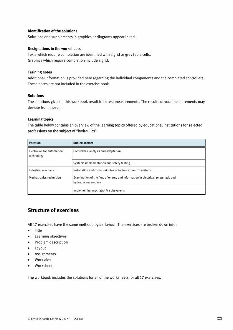
Learning topics The table below contains an overview of the learning topics offered by educational institutions for selected
professions on the subject of “hydraulics”.
Vocation Subject matter
Electrician for automation
technology
Controllers, analysis and adaptation
Systems implementation and safety testing
Industrial mechanic Installation and commissioning of technical control systems
Mechatronics technician Examination of the flow of energy and information in electrical, pneumatic and
hydraulic assemblies
Implementing mechatronic subsystems
Structure of exercises
All 17 exercises have the same methodological layout. The exercises are broken down into:
• Title
• Learning objectives
• Problem description
• Layout
• Assignments
• Work aids
• Worksheets
The workbook includes the solutions for all of the worksheets for all 17 exercises.
XXII © Festo Didactic GmbH & Co. KG 551141
Component designations
Pneumatic components are designated in circuit diagrams in accordance with ISO 1219-2. All of the
components included in any given circuit have the same primary identifying number. Letters are assigned
depending on each respective type of component. Consecutive numbers are assigned if several components
of the same type are included within a single circuit.
Cylinders: 1A1, 2A1, 2A2 ...
Valves: 1V1, 1V2, 1V3, 2V1, 2V2, 3V1 ...
Signal input: 1S1, 1S2 ...
Accessories: 0Z1, 0Z2, 1Z1 ...
CD-ROM contents
The workbook is included on the CD-ROM as a PDF file. The CD-ROM also provides you with additional media.
The CD-ROM contains the following folders:
• FluidSIM® circuit diagrams
• Images
• Operating instructions
• Presentations
FluidSIM® circuit diagrams FluidSIM® circuit diagrams for all of the exercises included in the technology package are contained in this
directory.
Images Photos and graphics of components and industrial applications are made available. These can be used to
illustrate individual tasks. Project presentations can also be supplemented with these illustrations.
Operating instructions Operating instructions for the components included in the training package are available. These instructions
are helpful when using and commissioning the components.
Presentations This directory contains short presentations for the components included in the training package. They can
be used, for example, for the creation of project presentations.
© Festo Didactic GmbH & Co. KG 551141 1
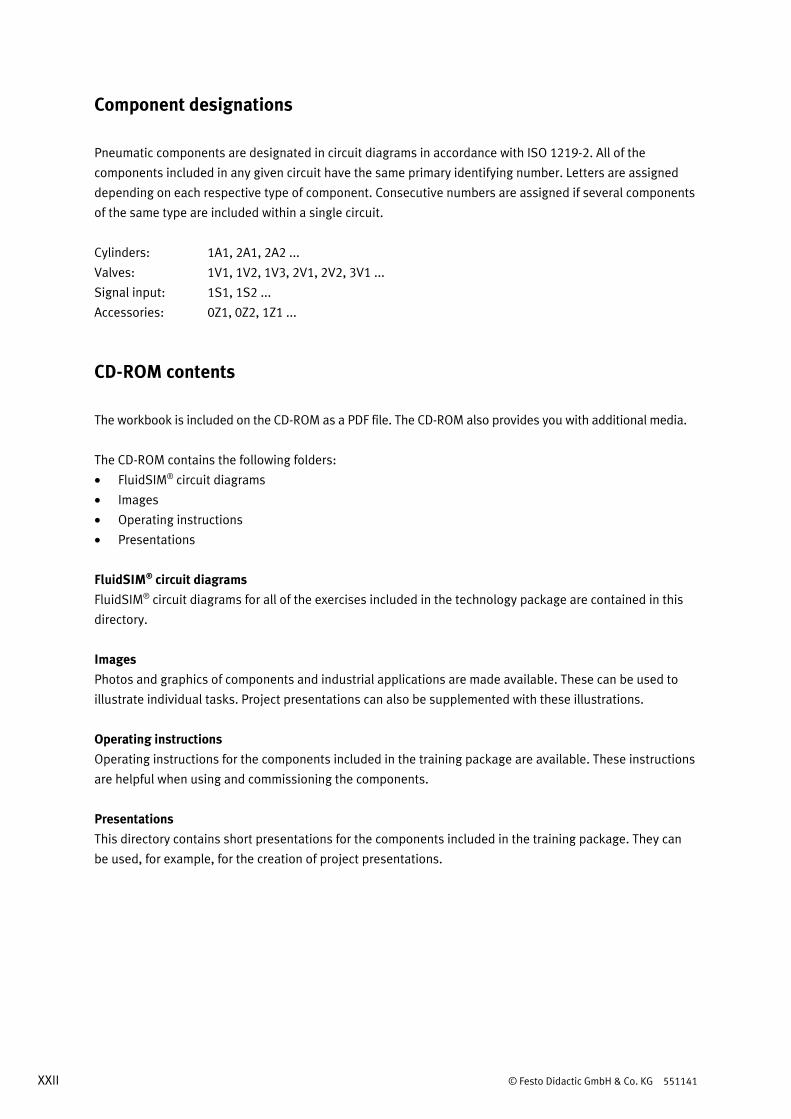
Table of contents
Exercises and solutions
Exercise 1: Setting up a hydraulic workstation _________________________________________________ 3
Exercise 2: Commissioning a two-column hydraulic press ______________________________________ 13
Exercise 3: Measuring the characteristic pump curve __________________________________________ 21
Exercise 4: Measuring the opening characteristics of a pressure-relief valve _______________________ 33
Exercise 5: Unloading a paper machine _____________________________________________________ 41
Exercise 6: Opening a hardening furnace ____________________________________________________ 51
Exercise 7: Opening and closing a boiler door ________________________________________________ 59
Exercise 8: Dimensioning an assembly device ________________________________________________ 69
Exercise 9: Sorting shipping crates_________________________________________________________ 73
Exercise 10: Measuring the characteristic curve of a flow control valve_____________________________ 83
Exercise 11: Adjusting stroke speed at a hydraulic lift __________________________________________ 93
Exercise 12: Optimising an embossing machine ______________________________________________ 103
Exercise 13: Matching retracting and advancing speed ________________________________________ 115
Exercise 14: Securing a cylinder against unintentional retraction ________________________________ 123
Exercise 15: Correcting misalignment of a conveyor belt _______________________________________ 133
Exercise 16: Counter-pressure for closing a bulkhead door _____________________________________ 139
Exercise 17: Loading and unloading buckets _________________________________________________ 145

Table of contents
2 © Festo Didactic GmbH & Co. KG 551141
© Festo Didactic GmbH & Co. KG 551141 3
Exercise 1 Setting up a hydraulic workstation
Learning objectives After completing this exercise:
• You will be familiar with the setup and function of a hydro pump.
• You will be familiar with the most important characteristics of a hydro pump.
• You will be able to select a hydraulic power unit on the basis of specified requirements.
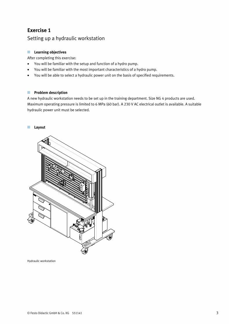
Problem description A new hydraulic workstation needs to be set up in the training department. Size NG 4 products are used.
Maximum operating pressure is limited to 6 MPa (60 bar). A 230 V AC electrical outlet is available. A suitable
hydraulic power unit must be selected.
Layout
Hydraulic workstation
Exercise 1 – Setting up a hydraulic workstation
4 © Festo Didactic GmbH & Co. KG 551141
Assignments 1. Describe the setup and function of a hydro pump.
2. Calculate the volumetric flow rate of a hydro pump.
3. Calculate the efficiency of a hydro pump.
4. Select a hydraulic power unit on the basis of specified requirements.
Work aids • Data sheets
• Hydraulics textbook
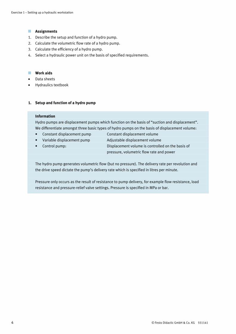
1. Setup and function of a hydro pump
Information
Hydro pumps are displacement pumps which function on the basis of “suction and displacement”.
We differentiate amongst three basic types of hydro pumps on the basis of displacement volume:
• Constant displacement pump Constant displacement volume
• Variable displacement pump Adjustable displacement volume
• Control pump: Displacement volume is controlled on the basis of
pressure, volumetric flow rate and power
The hydro pump generates volumetric flow (but no pressure). The delivery rate per revolution and
the drive speed dictate the pump’s delivery rate which is specified in litres per minute.
Pressure only occurs as the result of resistance to pump delivery, for example flow resistance, load
resistance and pressure-relief valve settings. Pressure is specified in MPa or bar.
Exercise 1 – Setting up a hydraulic workstation
© Festo Didactic GmbH & Co. KG 551141 5
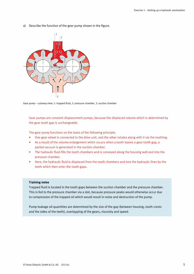
a) Describe the function of the gear pump shown in the figure.
3
2
1
Gear pump – cutaway view; 1: trapped fluid, 2: pressure chamber, 3: suction chamber
Gear pumps are constant-displacement pumps, because the displaced volume which is determined by
the gear tooth gap is unchangeable.
The gear pump functions on the basis of the following principle:
• One gear wheel is connected to the drive unit, and the other rotates along with it via the toothing.
• As a result of the volume enlargement which occurs when a tooth leaves a gear tooth gap, a
partial vacuum is generated in the suction chamber.
• The hydraulic fluid fills the tooth chambers and is conveyed along the housing wall and into the
pressure chamber.
• Here, the hydraulic fluid is displaced from the tooth chambers and into the hydraulic lines by the
teeth which then enter the tooth gaps.
Training notes
Trapped fluid is located in the tooth gaps between the suction chamber and the pressure chamber.
This is fed to the pressure chamber via a slot, because pressure peaks would otherwise occur due
to compression of the trapped oil which would result in noise and destruction of the pump.
Pump leakage oil quantities are determined by the size of the gap (between housing, tooth crests
and the sides of the teeth), overlapping of the gears, viscosity and speed.
Exercise 1 – Setting up a hydraulic workstation
6 © Festo Didactic GmbH & Co. KG 551141
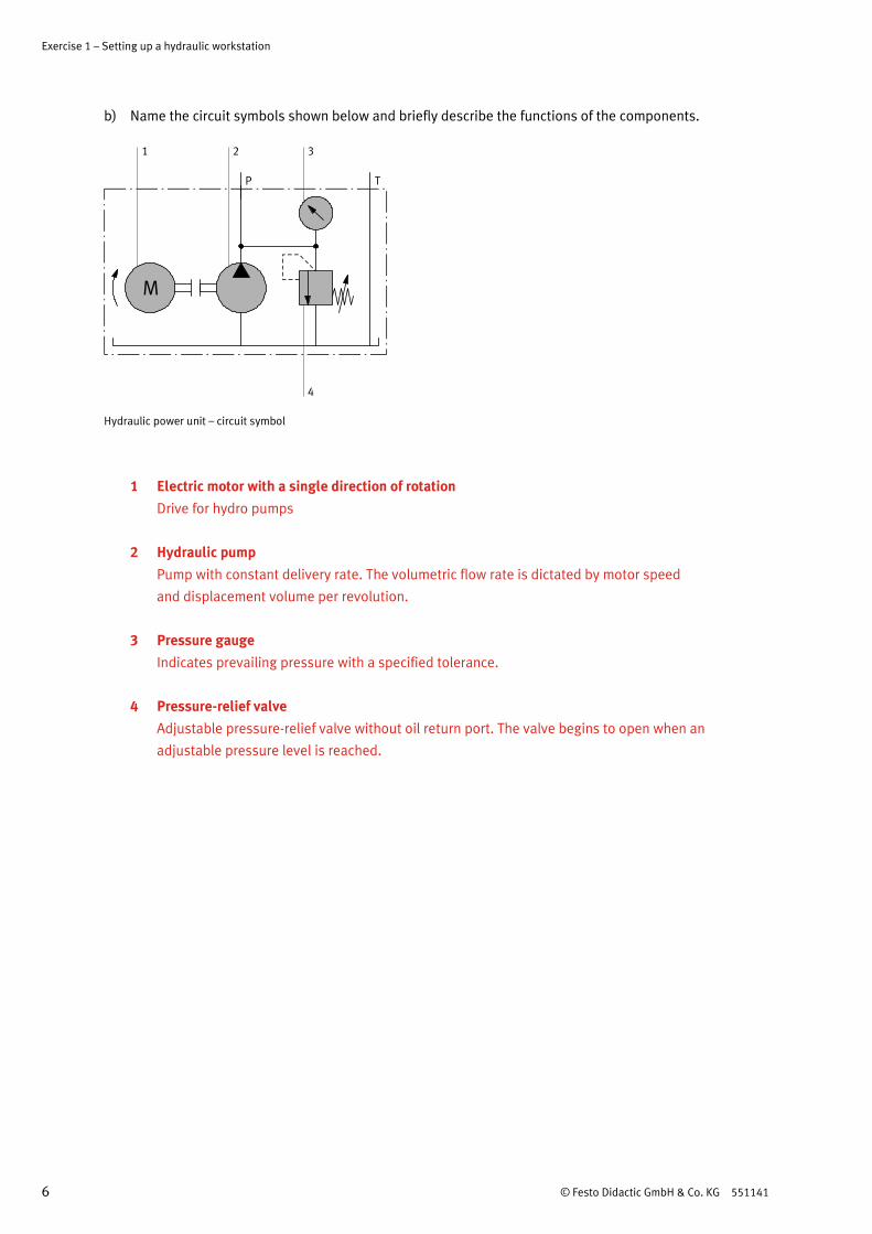
b) Name the circuit symbols shown below and briefly describe the functions of the components.
P T
M
1
4
2 3
Hydraulic power unit – circuit symbol
1 Electric motor with a single direction of rotation
Drive for hydro pumps
2 Hydraulic pump
Pump with constant delivery rate. The volumetric flow rate is dictated by motor speed
and displacement volume per revolution.
3 Pressure gauge
Indicates prevailing pressure with a specified tolerance.
4 Pressure-relief valve
Adjustable pressure-relief valve without oil return port. The valve begins to open when an
adjustable pressure level is reached.
Exercise 1 – Setting up a hydraulic workstation
© Festo Didactic GmbH & Co. KG 551141 7
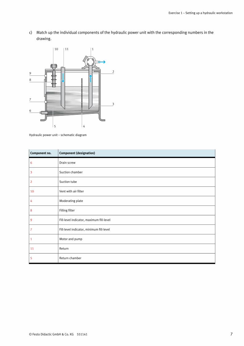
c) Match up the individual components of the hydraulic power unit with the corresponding numbers in the
drawing.
10
8
9
1
2
3
4
6
5
11
7
Hydraulic power unit – schematic diagram
Component no. Component (designation)
6 Drain screw
3 Suction chamber
2 Suction tube
10 Vent with air filter
4 Moderating plate
8 Filling filter
9 Fill-level indicator, maximum fill-level
7 Fill-level indicator, minimum fill-level
1 Motor and pump
11 Return
5 Return chamber
Exercise 1 – Setting up a hydraulic workstation
8 © Festo Didactic GmbH & Co. KG 551141
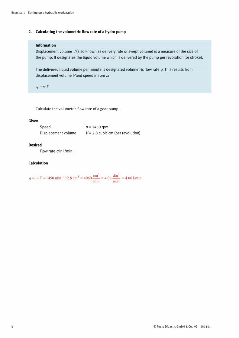
2. Calculating the volumetric flow rate of a hydro pump
Information
Displacement volume V (also known as delivery rate or swept volume) is a measure of the size of
the pump. It designates the liquid volume which is delivered by the pump per revolution (or stroke).
The delivered liquid volume per minute is designated volumetric flow rate q. This results from
displacement volume V and speed in rpm n:
q n V= ⋅
– Calculate the volumetric flow rate of a gear pump.
Given Speed n = 1450 rpm
Displacement volume V = 2.8 cubic cm (per revolution)
Desired Flow rate q in l/min.
Calculation
3 3-1 3
cm dm1450 min 2.8 cm = 4060 = 4.06 = 4.06 l/minmin min
q n V= ⋅ =
Exercise 1 – Setting up a hydraulic workstation
© Festo Didactic GmbH & Co. KG 551141 9
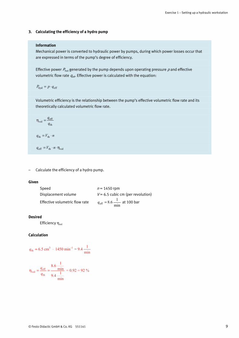
3. Calculating the efficiency of a hydro pump
Information
Mechanical power is converted to hydraulic power by pumps, during which power losses occur that
are expressed in terms of the pump’s degree of efficiency.
Effective power Phyd generated by the pump depends upon operating pressure p and effective
volumetric flow rate qeff. Effective power is calculated with the equation:
hyd effP p q= ⋅
Volumetric efficiency is the relationship between the pump’s effective volumetric flow rate and its
theoretically calculated volumetric flow rate.
effvol
th
η =
th thq V n= ⋅
eff th volq V n= ⋅ ⋅η
– Calculate the efficiency of a hydro pump.
Given
Speed n = 1450 rpm
Displacement volume V = 6.5 cubic cm (per revolution)
Effective volumetric flow rate effl8.6
minq = at 100 bar
Desired Efficiency ηvol
Calculation
3 -1th
l6.5 cm 1450 min = 9.4min
q = ⋅
effvol
th
l8.6min = 0.92 = 92 %
l9.4min
η = =
Exercise 1 – Setting up a hydraulic workstation
10 © Festo Didactic GmbH & Co. KG 551141
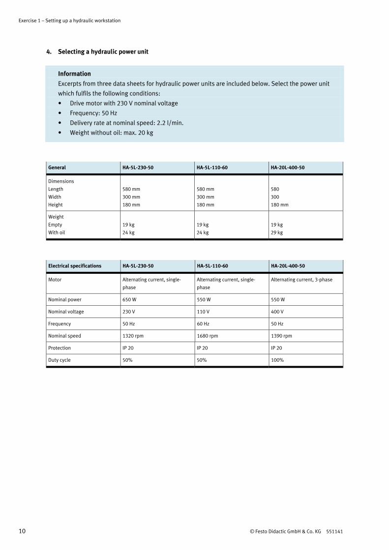
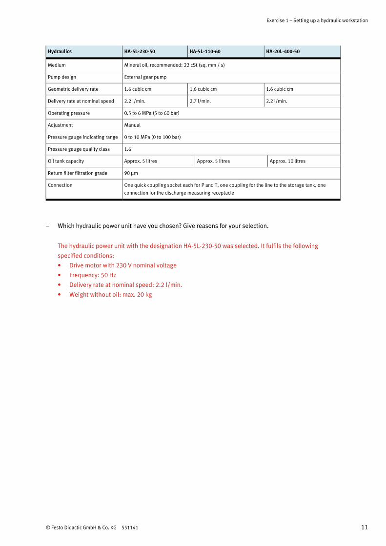
4. Selecting a hydraulic power unit
Information
Excerpts from three data sheets for hydraulic power units are included below. Select the power unit
which fulfils the following conditions:
• Drive motor with 230 V nominal voltage
• Frequency: 50 Hz
• Delivery rate at nominal speed: 2.2 l/min.
• Weight without oil: max. 20 kg
General HA-5L-230-50 HA-5L-110-60 HA-20L-400-50
Dimensions
Length
Width
Height
580 mm
300 mm
180 mm
580 mm
300 mm
180 mm
580
300
180 mm
Weight
Empty
With oil
19 kg
24 kg
19 kg
24 kg
19 kg
29 kg
Electrical specifications HA-5L-230-50 HA-5L-110-60 HA-20L-400-50
Motor Alternating current, single-
phase
Alternating current, single-
phase
Alternating current, 3-phase
Nominal power 650 W 550 W 550 W
Nominal voltage 230 V 110 V 400 V
Frequency 50 Hz 60 Hz 50 Hz
Nominal speed 1320 rpm 1680 rpm 1390 rpm
Protection IP 20 IP 20 IP 20
Duty cycle 50% 50% 100%
Exercise 1 – Setting up a hydraulic workstation
© Festo Didactic GmbH & Co. KG 551141 11
Hydraulics HA-5L-230-50 HA-5L-110-60 HA-20L-400-50
Medium Mineral oil, recommended: 22 cSt (sq. mm / s)
Pump design External gear pump
Geometric delivery rate 1.6 cubic cm 1.6 cubic cm 1.6 cubic cm
Delivery rate at nominal speed 2.2 l/min. 2.7 l/min. 2.2 l/min.
Operating pressure 0.5 to 6 MPa (5 to 60 bar)
Adjustment Manual
Pressure gauge indicating range 0 to 10 MPa (0 to 100 bar)
Pressure gauge quality class 1.6
Oil tank capacity Approx. 5 litres Approx. 5 litres Approx. 10 litres
Return filter filtration grade 90 μm
Connection One quick coupling socket each for P and T, one coupling for the line to the storage tank, one
connection for the discharge measuring receptacle
– Which hydraulic power unit have you chosen? Give reasons for your selection.
The hydraulic power unit with the designation HA-5L-230-50 was selected. It fulfils the following
specified conditions:
• Drive motor with 230 V nominal voltage
• Frequency: 50 Hz
• Delivery rate at nominal speed: 2.2 l/min.
• Weight without oil: max. 20 kg


![AIRPORT STANDARDS DIRECTIVE 501 [ASD 501]](https://img.pdfslide.net/doc/110x75/618e31252c83855c9d65730e/airport-standards-directive-501-asd-501.jpg)