Embed Size (px)
Citation preview
UNIT – IV
HYDRO ELECTRIC POWER PLANT
PART – A
1. Define – Dam
head.
A dam is a barrier to confine or raise water for storage or diversion to create a hydraulic
2. Define – Surge tank
A surge tank is a small reservoir or tank in which the water level rises or falls to reduce the
pressure swings so that they are not transmitted in full to a closed circuit.
3. Write the purpose of Draft tube.
A draft tube serves the following two purposes:
1. It allows the turbine to be set above tail-water level, without loss of head, to
facilitate inspection and maintenance.
2. It regains, by diffuser action, the major portion of the kinetic energy delivered to it
from the runner.
4. Define – Base load and Peak load plants
The plants which cater to the base load of the system are called ‘base load plants’ whereas
the plants which can supply the power during peak loads are known as peak load plants.
5. Define – Specific speed
The specific speed of a turbine is defined as the speed of a geometrically similar turbine
that would develop one brake horse power under a head of one metre.
6. Define – Pelton turbine
The Pelton turbine is a tangential flow impulse turbine. The pressure over the Pelton wheel
is constant and equal to atmosphere, so that energy transfer occurs due to purely impulse action.
7. Define – Francis water turbine
The modern Francis water turbine is an inward mixed flow reaction turbine. It operates
under medium heads and also requires medium quantity of water.
8. Differentiate propeller and Kaplan turbine?
In the propeller turbine the runner blades are fixed and non-adjustable. In Kaplan turbine,
which is a modification of propeller turbine the runner blades are adjustable and can be rotated
about the pivots fixed to the boss of the runner.
9. What are the Element of Hydel Power Plant?
Elements of Hydel Power Plant:
1. Water reservoir,
2. Dam,
3. Spillway,
4. Pressure tunnel,
5. Penstock,
6. Surge tank,
7. Water turbine,
8. Draft tube,
9. Tail race,
10. Step-up transformer,
11. Power house.
10. Write the Advantages of Hydro-electric power plants?
1. Water is a renewable source of energy. Water which is the operating fluid, is neither
consumed nor converted into something else,
2. Water is the cheapest source of energy because it exists as a free gift of nature. The fuels
needed for the thermal, diesel and nuclear plants are exhaustible and expensive.
3. There is no ash disposal problem as in the case of thermal power plant.
11. Write the classification of Hydro turbines?
Hydraulic turbines are classified as follows:
1) According to the head and quantity of water available, 2) According to the name of the originator,
3) According to the action of water on the moving blades,
4) According to the direction of flow of water in the runner,
5) According to the disposition of the turbine shaft,
6) According to the specific speed N.
12. Define – Governing Mechanism
When the load on the turbine changes, the speed may also change. (i.e., without load the
speed increases and with over load, the speed decreases). Hence, the speed of the runner must be
maintained constant to have a constant speed of generator. This is done by controlling the
quantity of water flowing on the runner according to the load variations. This speed regulation is
known as governing and it is usually done automatically by a governor.
13. What are the functions of draft tubes?
1) Increase in efficiency,
2) Negative head.
14. Write the two types of Draft tubes?
The draft tubes are of the following three types:
1) Conical or divergent draft tube,
2) Elbow type draft tube,
3) Hydracone or Moody spreading draft tube.
PART – B 1. Draw the Layout diagram of Hydro Power Plant and also explain the components and
working of Hydro power plant?
Introduction
Hydro-electric power plant utilizes the potential energy of water stored in a dam built
across the river. The potential energy of water is used to run water turbine to which the electric
generator is coupled. The mechanical energy available at the shaft of the turbine is converted into
electrical energy means of the generator.
ELEMENTS OF HYDEL POWER PLANT
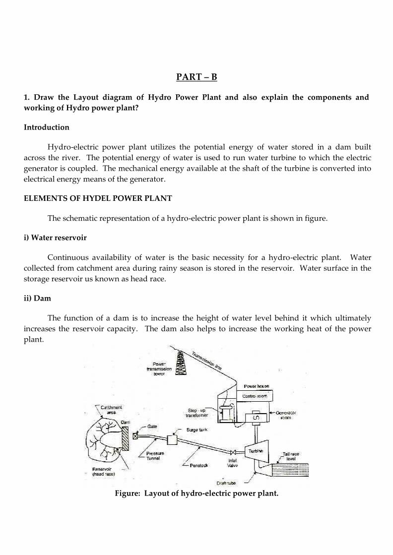
The schematic representation of a hydro-electric power plant is shown in figure.
i) Water reservoir
Continuous availability of water is the basic necessity for a hydro-electric plant. Water
collected from catchment area during rainy season is stored in the reservoir. Water surface in the
storage reservoir us known as head race.
ii) Dam
The function of a dam is to increase the height of water level behind it which ultimately
increases the reservoir capacity. The dam also helps to increase the working heat of the power
plant.
Figure: Layout of hydro-electric power plant.
iii) Spillway
Water after a certain level in the reservoir overflows through spillway without allowing the
increase in water level in the reservoir during rainy season
iv) Pressure tunnel
It carries water from the reservoir to surge tank.
v) Penstock
Water from surge tank is taken to the turbine by means of penstocks, made up of reinforced
concrete pipes or steel.
vi) Surge tank
There is sudden increase of pressure in the penstock due to sudden backflow of water, as
load on the turbine is reduced. The sudden rise of pressure in the penstock is known as water
hammer. The surge tank is introduced between the dam and the power house to keep in
reducing the sudden rise of pressure in the penstock. Otherwise penstock will be damaged by the
water hammer.
vii) Water turbine
Water through the penstock enters into the turbine through and inlet valve. Prime movers
which are in common use are Pelton turbine, Francis turbine and Kaplan turbine. The potential
energy of water entering the turbine is converted into mechanical energy. The mechanical energy
available at the turbine shaft is used to run the electric generator. The water is then discharged
through the draft tube.
viii) Draft tube
level.
It is connected to the outlet of the turbine. It allows the turbine to be placed over tail race
ix) Tail race
Tail race is a water way to lead the water discharged from the turbine to the river. The
water held in the tail race is called tail race water level.
x) Step-up transformer
Its function is to raise the voltage generated at the generator terminating before
transmitting the power to consumers.
xi) Power house
The power house accommodates the turbine, generator, transformer and control room.
Classification of Hydro-Power plants
Hydro-plants are classified according to the head of water under which they work.
When the operating head of water exceeds 70 metres, the plant is known as ‚high head
power plant‛. Pelton turbine is used as prime mover in such power plants.
When the head of water ranges from 15 to 70 metres then the power plant is known as
‚medium head plant‛. It uses Francis turbine.
When the head is less than 15 metres the plant is named as ‚low head plant‛. It uses
Francis or Kaplan turbine as prime mover.
2. Write the advantages and disadvantages of Hydro-Electric Power plant.
Advantages:
1. Water is renewable source of energy. Water which is the operating fluid, is neither
consumed nor converted into something else.
2. Water is the cheapest source of energy because it exists as a free gift of nature. The fuels
needed for the thermal, diesel and nuclear plants are exhaustible and expensive.
3. There is no ash disposal problem as in the case of thermal power plant.
4. Hydro-plant does not pose the problem of air pollution as in the case of thermal plant or
radiation hazards as in the case of nuclear plant.
5. Variable loads do not affect the efficiency in the case of a hydro-plant.
6. Life of hydro-plant is very long (1 to 2 centuries) compared with thermal plant (3 to 4
decades). This is because the hydro-plants operate at atmospheric temperature, whereas
thermal plants operate at very high temperature (about 500 to 800C).
7. Hydro-plant provides additional benefits like irrigation, flood control, fishery and
recreation.
8. The water storage of hydro-plant can also be used for domestic water supply.
9. Auxiliaries needed for the hydro-plant are less compared to thermal plant of equal capacity.
10. It requires less supervise staff.
11. Maintenance cost is low.
Disadvantages:
1. Hydro-plants are generally situated away from the load centres. Hence long transmission
lines are required for delivery of power. This increases the cost of transmission lines and
also transmission losses. But a thermal plant can be located near the load centre, thereby
the transmission cost and transmission losses are considerably reduced.
2. The power produced by hydro-plant depends upon the quantity of water which in turn is
dependent upon the rainfall. The dry year affects the hydro-power generation
considerably.
3. Initial cost of the plant is high.
4. Erection of hydro-plant (construction of dam etc.) usually takes long period of time.
3. What are the classification of Hydro turbines?
Classification of Hydro Turbines
Hydraulic turbines are classified as follows:
1. According to the head and quantity of water available.
2. According to the name of the originator.
3. According to the action of water on the moving blades.
4. According to the direction of flow of water in the runner.
5. According to the disposition of the turbine shaft.
6. According to the specific speed N.
1. According to the head and Quality of water available
i) Impulse turbine: It requires high head and small quantity of flow.
ii) Reaction turbine: It requires low head and high rate of flow.
Actually there are two types of reaction turbines, one for a medium head and medium flow
and the other for a low head and large flow.
2. According to the name of the originator
i) Pelton turbine, named after Lester Allen Pelton of California (U.S.A). It is an impulse
type of turbine and is used for high head and low discharge.
ii) Francis turbine, named after James Bichens Francis. It is a reaction type of turbine from
medium high to medium low heads and medium small to medium large quantities of
water.
iii) Kaplan turbine, named after Dr. Victor Kaplan. It is a reaction type of turbine for low
heads and large quantities of flow.
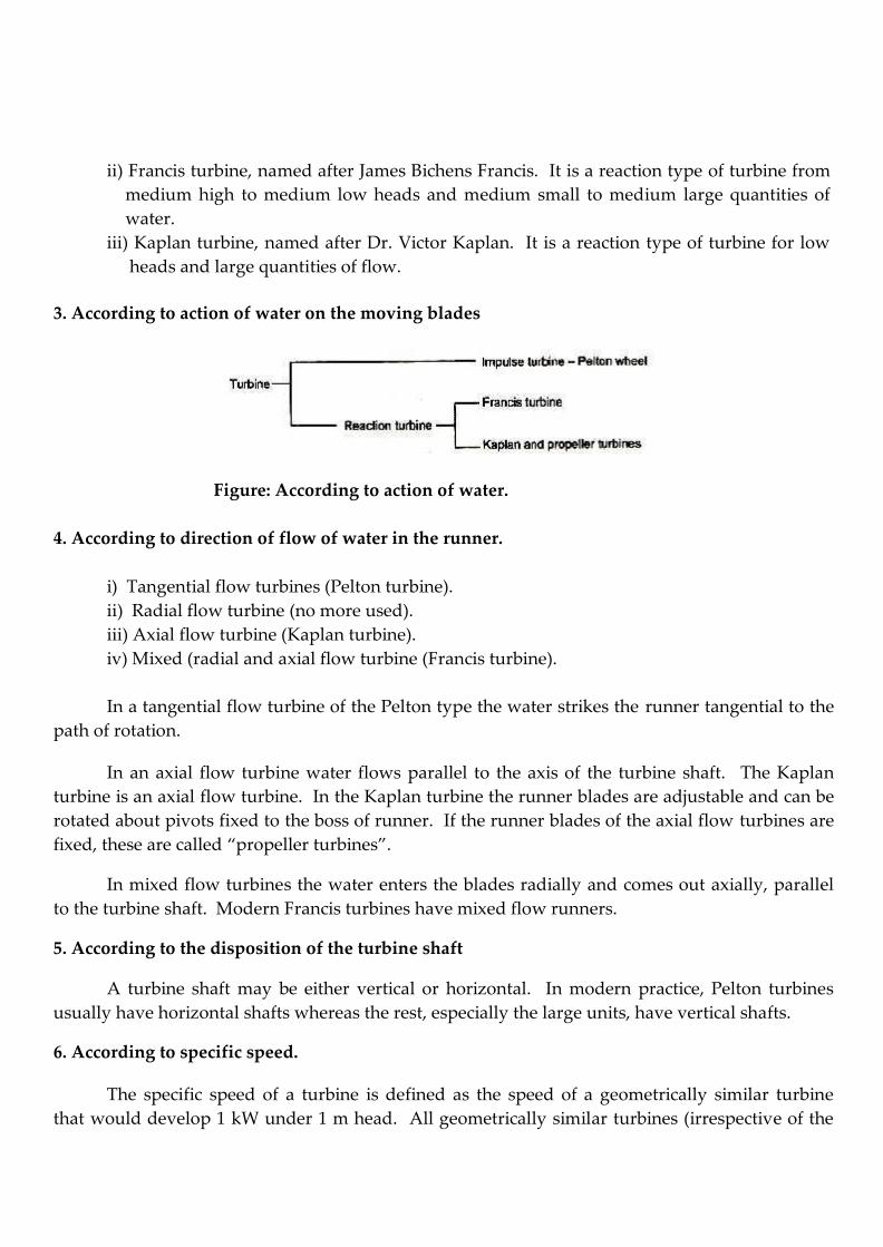
3. According to action of water on the moving blades
Figure: According to action of water.
4. According to direction of flow of water in the runner.
i) Tangential flow turbines (Pelton turbine).
ii) Radial flow turbine (no more used).
iii) Axial flow turbine (Kaplan turbine).
iv) Mixed (radial and axial flow turbine (Francis turbine).
In a tangential flow turbine of the Pelton type the water strikes the runner tangential to the
path of rotation.
In an axial flow turbine water flows parallel to the axis of the turbine shaft. The Kaplan
turbine is an axial flow turbine. In the Kaplan turbine the runner blades are adjustable and can be
rotated about pivots fixed to the boss of runner. If the runner blades of the axial flow turbines are
fixed, these are called ‚propeller turbines‛.
In mixed flow turbines the water enters the blades radially and comes out axially, parallel
to the turbine shaft. Modern Francis turbines have mixed flow runners.
5. According to the disposition of the turbine shaft
A turbine shaft may be either vertical or horizontal. In modern practice, Pelton turbines
usually have horizontal shafts whereas the rest, especially the large units, have vertical shafts.
6. According to specific speed.
The specific speed of a turbine is defined as the speed of a geometrically similar turbine
that would develop 1 kW under 1 m head. All geometrically similar turbines (irrespective of the
sizes) will have the same specific speeds when operating under the same head.
Specific speed, Ns = N P
H 5 / 4
Where N = The normal working speed,
P = Power output of the turbine, and
H = The net or effective head in metres.
Turbines with low specific speed work under a high head and low discharge conditions,
while high specific speed turbines work under a low head and high discharge conditions.
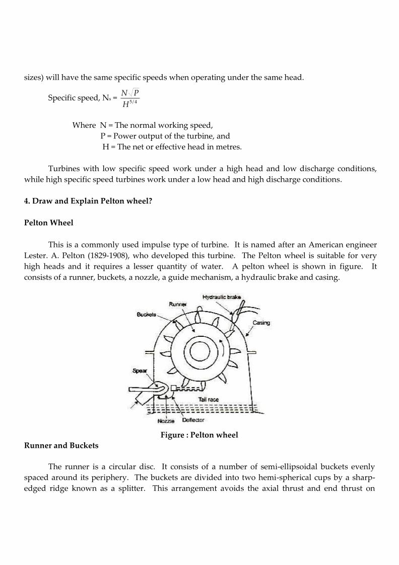
4. Draw and Explain Pelton wheel?
Pelton Wheel
This is a commonly used impulse type of turbine. It is named after an American engineer
Lester. A. Pelton (1829-1908), who developed this turbine. The Pelton wheel is suitable for very
high heads and it requires a lesser quantity of water. A pelton wheel is shown in figure. It
consists of a runner, buckets, a nozzle, a guide mechanism, a hydraulic brake and casing.
Runner and Buckets
Figure : Pelton wheel
The runner is a circular disc. It consists of a number of semi-ellipsoidal buckets evenly
spaced around its periphery. The buckets are divided into two hemi-spherical cups by a sharp-
edged ridge known as a splitter. This arrangement avoids the axial thrust and end thrust on
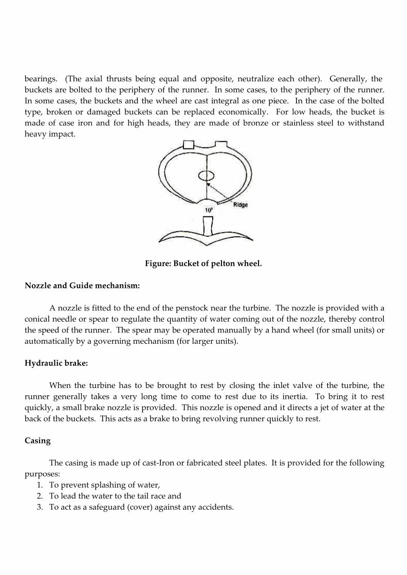
bearings. (The axial thrusts being equal and opposite, neutralize each other). Generally, the
buckets are bolted to the periphery of the runner. In some cases, to the periphery of the runner.
In some cases, the buckets and the wheel are cast integral as one piece. In the case of the bolted
type, broken or damaged buckets can be replaced economically. For low heads, the bucket is
made of case iron and for high heads, they are made of bronze or stainless steel to withstand
heavy impact.
Figure: Bucket of pelton wheel.
Nozzle and Guide mechanism:
A nozzle is fitted to the end of the penstock near the turbine. The nozzle is provided with a
conical needle or spear to regulate the quantity of water coming out of the nozzle, thereby control
the speed of the runner. The spear may be operated manually by a hand wheel (for small units) or
automatically by a governing mechanism (for larger units).
Hydraulic brake:
When the turbine has to be brought to rest by closing the inlet valve of the turbine, the
runner generally takes a very long time to come to rest due to its inertia. To bring it to rest
quickly, a small brake nozzle is provided. This nozzle is opened and it directs a jet of water at the
back of the buckets. This acts as a brake to bring revolving runner quickly to rest.
Casing
The casing is made up of cast-Iron or fabricated steel plates. It is provided for the following
purposes:
1. To prevent splashing of water,
2. To lead the water to the tail race and
3. To act as a safeguard (cover) against any accidents.
Working principle
The water is conveyed to the power house from the head race through penstocks. The
nozzle is fitted to the end of the penstock (power house end) delivers a high velocity water jet into
the bucket. One or more jets of water are arranged to impinge on the buckets tangentially. The
impact of water jet on the bucket causes the wheel to rotate, thus producing mechanical work. An
electric generator is coupled to the runner shaft and mechanical energy is converted into electrical
power.
After leaving the turbine wheel, water falls into the tail race. The Pelton wheel is located
above the tail race so that, the buckets do not splash the tail race water.
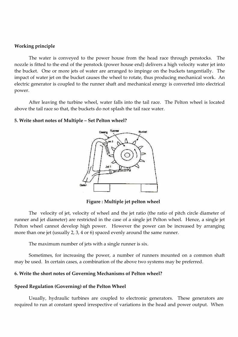
5. Write short notes of Multiple – Set Pelton wheel?
Figure : Multiple jet pelton wheel
The velocity of jet, velocity of wheel and the jet ratio (the ratio of pitch circle diameter of
runner and jet diameter) are restricted in the case of a single jet Pelton wheel. Hence, a single jet
Pelton wheel cannot develop high power. However the power can be increased by arranging
more than one jet (usually 2, 3, 4 or 6) spaced evenly around the same runner.
The maximum number of jets with a single runner is six.
Sometimes, for increasing the power, a number of runners mounted on a common shaft
may be used. In certain cases, a combination of the above two systems may be preferred.
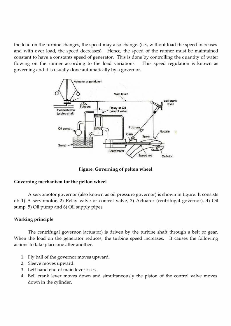
6. Write the short notes of Governing Mechanisms of Pelton wheel?
Speed Regulation (Governing) of the Pelton Wheel
Usually, hydraulic turbines are coupled to electronic generators. These generators are required to run at constant speed irrespective of variations in the head and power output. When
the load on the turbine changes, the speed may also change. (i.e., without load the speed increases
and with over load, the speed decreases). Hence, the speed of the runner must be maintained
constant to have a constants speed of generator. This is done by controlling the quantity of water
flowing on the runner according to the load variations. This speed regulation is known as
governing and it is usually done automatically by a governor.
Figure: Governing of pelton wheel
Governing mechanism for the pelton wheel
A servomotor governor (also known as oil pressure governor) is shown in figure. It consists
of: 1) A servomotor, 2) Relay valve or control valve, 3) Actuator (centrifugal governor), 4) Oil
sump, 5) Oil pump and 6) Oil supply pipes
Working principle
The centrifugal governor (actuator) is driven by the turbine shaft through a belt or gear.
When the load on the generator reduces, the turbine speed increases. It causes the following
actions to take place one after another.
1. Fly ball of the governor moves upward.
2. Sleeve moves upward.
3. Left hand end of main lever rises.
4. Bell crank lever moves down and simultaneously the piston of the control valve moves
down in the cylinder.
The movement of bell crank lever brings the deflector in front of the jet. The deflector
diverts a portion of the water jet away from the runner buckets. Thus, rapid closure of the nozzle
opening is eliminated and at the same time the quantity of water striking the runner is reduced.
The rapid closing of the nozzle increases the pressure of water which may result in water hammer
problems.
The downward movement of the piston in the control valve forces of under pressure from
the control valve to the left side of the piston in servomotor. The piston of the servomotor moves
to the right pushing the spear forward. The oil in the right side is returned to the oil sump. The
forward motion of the spear reduces the opening of the nozzle. Consequently, the rate of flow is
decreased and normal speed is restored. Once the normal turbine speed is restored, the main
lever returns to its initial position, the deflector is brought to its original position by means of cam
arrangement.
When the load on the generator increases, the turbine speed decreases. This causes the
following actions to take place one after another.
1. Fly balls move downward.
2. Sleeve moves downward.
3. Left hand end of the main lever lowers down.
4. The piston in the control valve moves upward in the cylinder.
5. Oil under pressure is forced from the control valve to the right side of the piston in the
servomotor.
6. Servomotor piston moves to the left pushing the oil in the less side to the oil sump.
Simultaneously, the spear moves backward.
The backward movement of the spear increases the opening of the nozzle outlet. Thus, a
large quantity of water strikes the runner and the normal speed of the turbine is restored.
7. Draw and Explain the construction and working principle of Francis turbine?
Reaction turbines
Reaction turbines operate under pressure of water. Only a part of the total head of water is
converted into a kinetic head before it reaches the runner. The water completely fills all the
passages in the runner (turbine runs full). Water enters the wheel due to the head of water at
inlet and flows through the vanes. When flowing through the vanes, both the pressure and
velocity change. The water leaves the turbine to the tail race at a reduced pressure and velocity.
Reaction turbines may be: 1) Radially inward flow turbines, 2) Outward flow turbines, 3)
Axial flow turbines, 4) Mixed flow turbines.
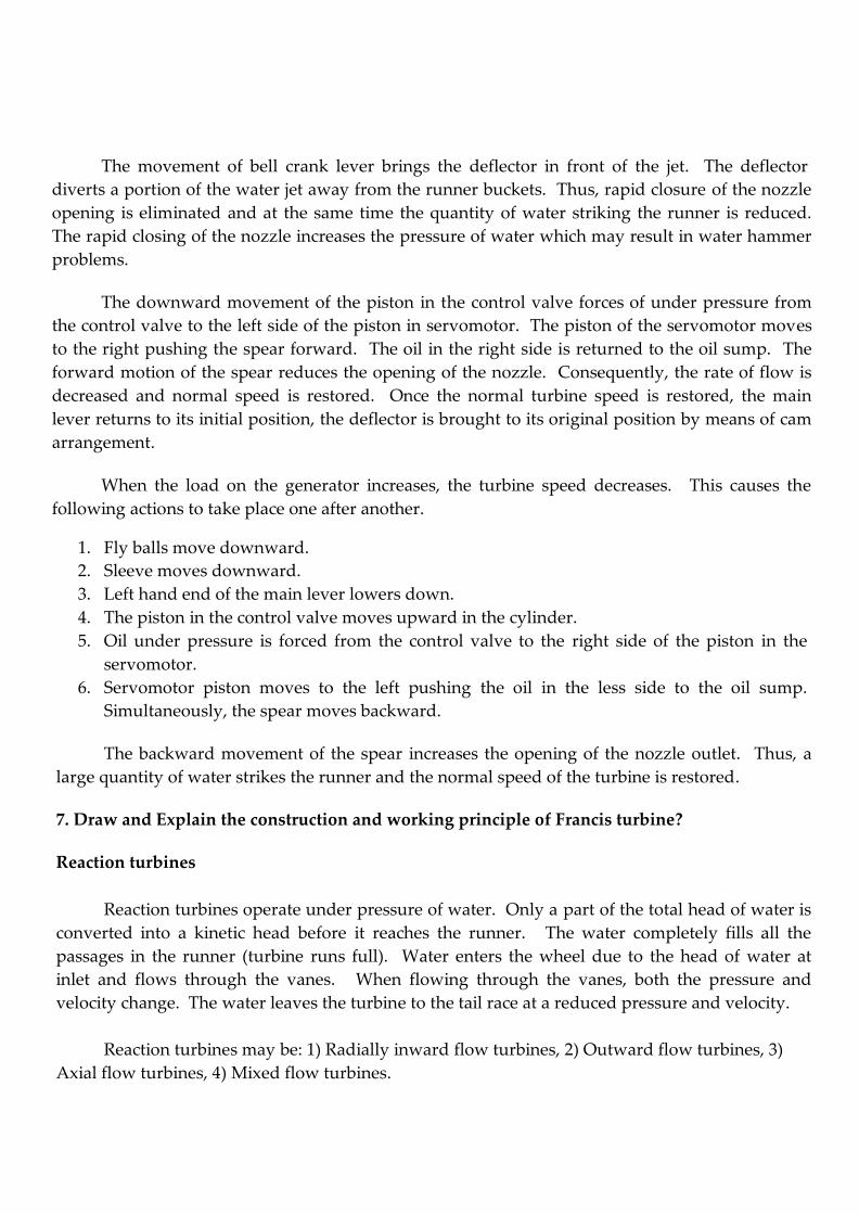
Francis Turbine
Figure Francis Turbine
The modern Francis turbine is a mixed flow type of reaction turbine. In this, water under
pressure enters the runner towards the centre in a radial direction and leaves the runner axially. It
operates under medium heads and requires a moderate quantity of water.
Figure shows the parts of a Francis turbine. It consists of a scroll casing, stay ring, guide
mechanism, runner and draft tube.
a) Scroll Casing
Water from the penstock is received by a scroll casing. The scroll casing (also called spiral
casting) surrounds the guide wheel and runner. The cross-sectional area of the casing decreases
uniformly to distribute the water around the guide ring evenly. Also, this prevents eddy
formation. In bigger units, stay vanes are provided inside the casing to direct the water to the
guide vanes. The casing has inspection holes and provision for connecting a pressure gauge. The
casing is made of welded steel plates or cast steel.
b) Speed ring or Stay ring
The speed ring or stay ring consists of two rings held together by a series of fixed vanes
called stay vanes. This ring directs water from the scroll casing to the guide vanes. It also
transfers the loads (caused by the water pressure, weight of turbine and the weight of the
generator) to the foundation. It is made of cast iron, cast steel or fabricated plate steel.
c) Guide mechanism
The guide blades (wicket gates) are fitted between two rings in the form of a wheel known
as a guide wheel. The guide vanes guide the water to enter tangentially to the runner blades. The
air foil shape of the vanes prevent eddy formation and reduces frictional losses. Each guide vane
is pivoted and it can be rotated about its pivot by a system of levers and links. This rotation of
guide vanes alters the width of the water passage between them. Thus, water flowing into the
runner is varied accordingly to the requirement. The guide vanes are generally made of case steel
or stainless steel.
d) Runner
The runner consists of series of curved vanes. The vanes (16 to 24) are evenly arranged
around the circumference in the annualar space between two plates. The vanes are properly
shaped to receive the water without a shock. The runner is keyed to the shaft which may be
vertical or horizontal. The runner is made of cast iron for small turbines. In large turbines, the
runner is made of cast steel or stainless steel.
e) Draft tube
This is a pipe or passage which leads the water exhausted from the turbine into the tail
race. Its cross-section increases gradually towards the outlet. The bottom enlarged end is
submerged in a tail race water level. It is made of cast steel, welded plate steel or concrete.
f) Working principle
The water from the reservoir is carried to the turbine through penstocks and enters the
scroll casing. The casing distributes water evenly around the circumference of the turbine runner.
From the scroll casing, the water passes through the stay ring. This ring directs water to the guide
vanes or wicket gates. These guide vanes regulate the quantity of water supplied to the runner.
The air foil shape of the guide vanes allows the water to flow smoothly without a shock. The
water enters the runner with a low velocity and considerable pressure. As the water flows
through the runner, the direction of flow of waters changed from axial to radial. The pressure
energy is gradually converted into kinetic energy and the runner is rotated at high speed. This
torque is transmitted to the generator which is coupled to the runner shaft. After passing through
the runner water enters the tail race through a draft tube.
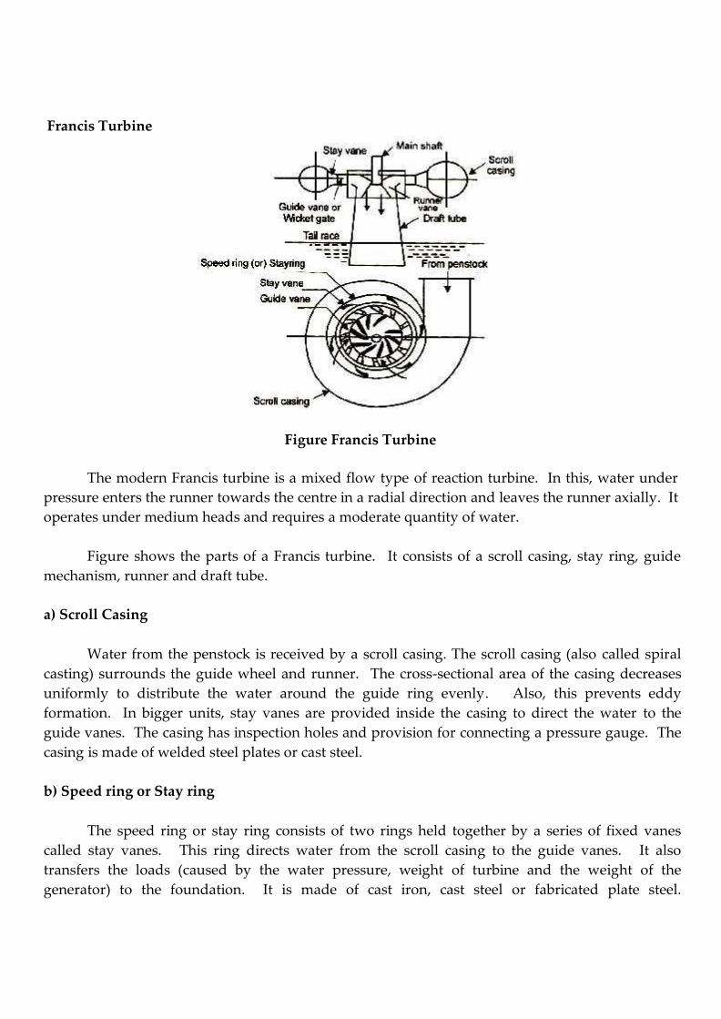
8. Write a short note of Francis turbine of Governing speed regulation of Francis turbine?
Governing of Francis turbine
In Francis turbine, guide blades are used for governing. These guide blades are pivoted
and they only connected to a regulating rings by means of levers and links. Two regulating rods
are connected to the ring and these rods actuated by the servomotor governor as shown in the
figure.
The actuator or pendulum is driven by the turbine. When the load on the generator
decreases, the turbine speed increases. The increased speed of the runner causes the following
actions to take place one after another.
1. The fly balls are moved upward.
2. The sleeve is raised.
3. Piston of the distributor valve (control valve) is moved downwards in the cylinder and
opens the port B.
4. Oil under pressure enters the left side of the piston in the servometer.
5. Piston in the servometer moves to the right.
6. Oil in the right side of the piston returns to the oil sump through port ‘A’.
7. At the same time, the regulating ring is rotated and the guide blades are moved. This
reduces the area of flow passage between the guide vanes.
Figure: Governing of Francis turbine
Thus the rate of flow of water striking the runner is reduced. When the speed comes to the
normal, the main lever, actuator and distribution valve attain their original position.
Similarly, when the load on the turbine increases, the regulating ring moves in the opposite
direction. This increases the flow passage between the guide blades. Hence more quantity of
water strikes the runner to meet the increased load demand. Thus, the governor maintains a
constant speed irrespective of the load on the turbine.
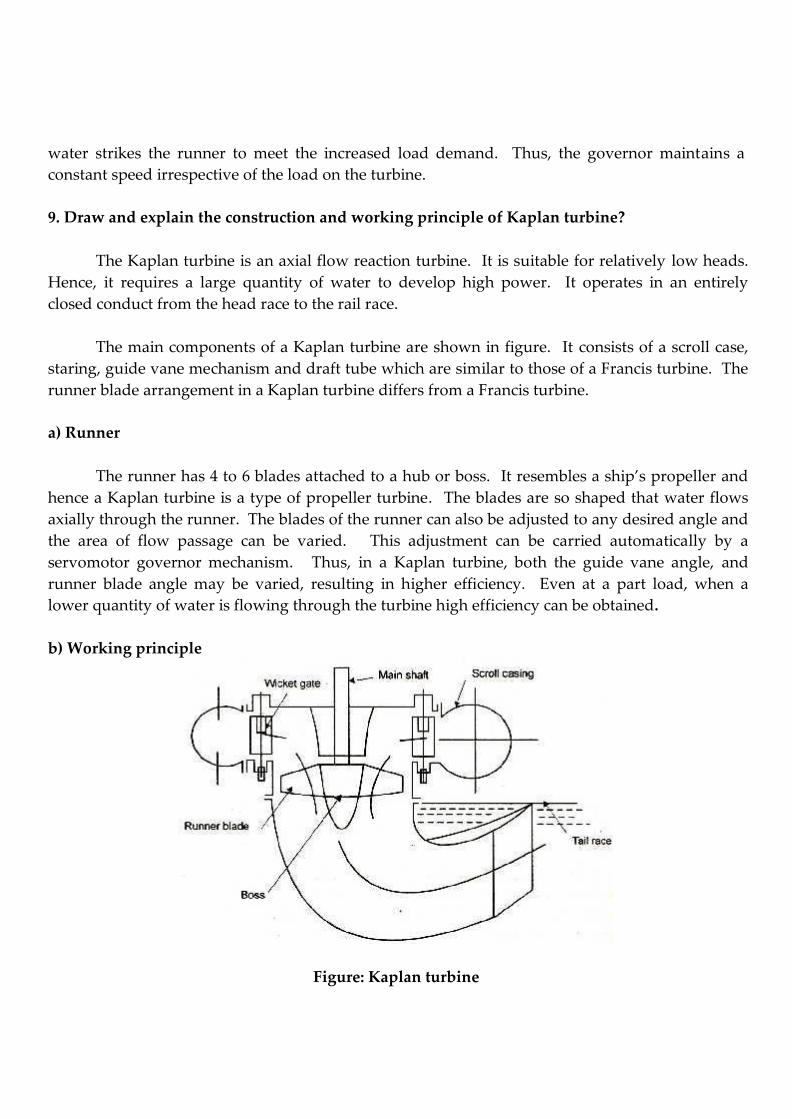
9. Draw and explain the construction and working principle of Kaplan turbine?
The Kaplan turbine is an axial flow reaction turbine. It is suitable for relatively low heads.
Hence, it requires a large quantity of water to develop high power. It operates in an entirely
closed conduct from the head race to the rail race.
The main components of a Kaplan turbine are shown in figure. It consists of a scroll case,
staring, guide vane mechanism and draft tube which are similar to those of a Francis turbine. The
runner blade arrangement in a Kaplan turbine differs from a Francis turbine.
a) Runner
The runner has 4 to 6 blades attached to a hub or boss. It resembles a ship’s propeller and
hence a Kaplan turbine is a type of propeller turbine. The blades are so shaped that water flows
axially through the runner. The blades of the runner can also be adjusted to any desired angle and
the area of flow passage can be varied. This adjustment can be carried automatically by a
servomotor governor mechanism. Thus, in a Kaplan turbine, both the guide vane angle, and
runner blade angle may be varied, resulting in higher efficiency. Even at a part load, when a
lower quantity of water is flowing through the turbine high efficiency can be obtained.
b) Working principle
Figure: Kaplan turbine
The water from the scroll casing flows over the guide vanes. It is deflected through 90
between guide vanes and runner. Then, it flows axially into the runner. The blades are shaped
such that water flows axially in the runner. The force exerted on the blades causes the runner
shaft to rotate. This rotation is transmitted to the generator which is couple to the runner shaft.
After passing through the runner, the water enters the tailrace through a draft tube.
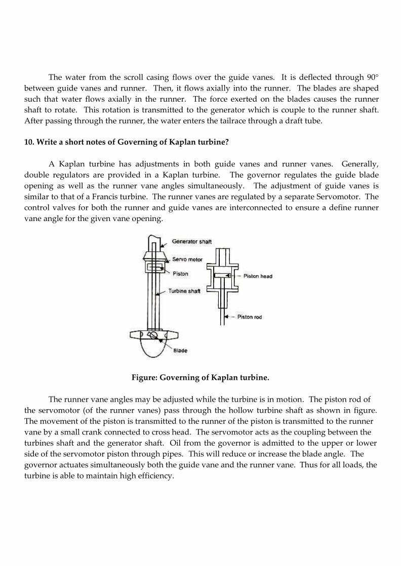
10. Write a short notes of Governing of Kaplan turbine?
A Kaplan turbine has adjustments in both guide vanes and runner vanes. Generally,
double regulators are provided in a Kaplan turbine. The governor regulates the guide blade
opening as well as the runner vane angles simultaneously. The adjustment of guide vanes is
similar to that of a Francis turbine. The runner vanes are regulated by a separate Servomotor. The
control valves for both the runner and guide vanes are interconnected to ensure a define runner
vane angle for the given vane opening.
Figure: Governing of Kaplan turbine.
The runner vane angles may be adjusted while the turbine is in motion. The piston rod of
the servomotor (of the runner vanes) pass through the hollow turbine shaft as shown in figure.
The movement of the piston is transmitted to the runner of the piston is transmitted to the runner
vane by a small crank connected to cross head. The servomotor acts as the coupling between the
turbines shaft and the generator shaft. Oil from the governor is admitted to the upper or lower
side of the servomotor piston through pipes. This will reduce or increase the blade angle. The
governor actuates simultaneously both the guide vane and the runner vane. Thus for all loads, the
turbine is able to maintain high efficiency.
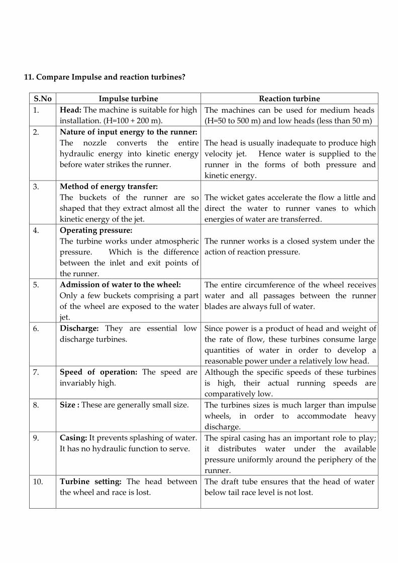
11. Compare Impulse and reaction turbines?
S.No Impulse turbine Reaction turbine
1. Head: The machine is suitable for high
installation. (H=100 + 200 m).
The machines can be used for medium heads
(H=50 to 500 m) and low heads (less than 50 m)
2. Nature of input energy to the runner:
The nozzle converts the entire
hydraulic energy into kinetic energy
before water strikes the runner.
The head is usually inadequate to produce high
velocity jet. Hence water is supplied to the
runner in the forms of both pressure and
kinetic energy.
3. Method of energy transfer:
The buckets of the runner are so
shaped that they extract almost all the
kinetic energy of the jet.
The wicket gates accelerate the flow a little and
direct the water to runner vanes to which
energies of water are transferred.
4. Operating pressure:
The turbine works under atmospheric
pressure. Which is the difference
between the inlet and exit points of
the runner.
The runner works is a closed system under the
action of reaction pressure.
5. Admission of water to the wheel:
Only a few buckets comprising a part
of the wheel are exposed to the water
jet.
The entire circumference of the wheel receives
water and all passages between the runner
blades are always full of water.
6. Discharge: They are essential low
discharge turbines.
Since power is a product of head and weight of
the rate of flow, these turbines consume large
quantities of water in order to develop a
reasonable power under a relatively low head.
7. Speed of operation: The speed are
invariably high.
Although the specific speeds of these turbines
is high, their actual running speeds are
comparatively low.
8. Size : These are generally small size. The turbines sizes is much larger than impulse
wheels, in order to accommodate heavy
discharge.
9. Casing: It prevents splashing of water.
It has no hydraulic function to serve.
The spiral casing has an important role to play;
it distributes water under the available
pressure uniformly around the periphery of the
runner.
10. Turbine setting: The head between
the wheel and race is lost.
The draft tube ensures that the head of water
below tail race level is not lost.
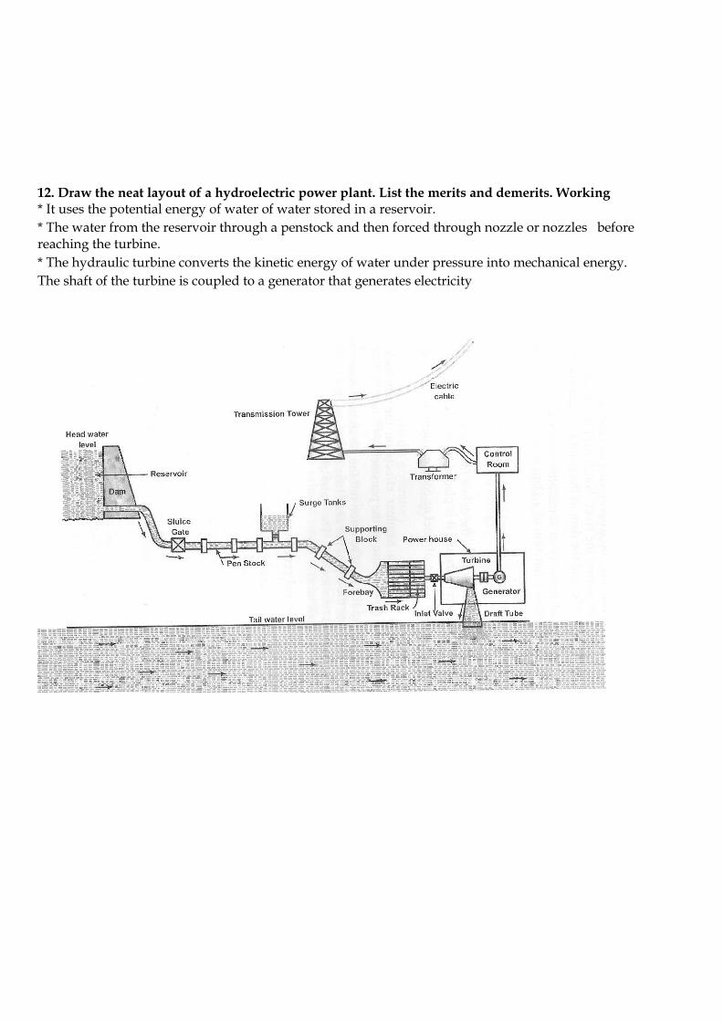
12. Draw the neat layout of a hydroelectric power plant. List the merits and demerits. Working * It uses the potential energy of water of water stored in a reservoir.
* The water from the reservoir through a penstock and then forced through nozzle or nozzles before reaching the turbine.
* The hydraulic turbine converts the kinetic energy of water under pressure into mechanical energy.
The shaft of the turbine is coupled to a generator that generates electricity
The electricity generated is fed to the step-up transformer to increase its voltage.
Power is fed to the transmission lines for distribution.
The output power of Hydel power plant depends on the head of water stored in the reservoir and the quantity of water discharged
Advantages of hydroelectric power plant 1. Plant doesn’t require any fuel, it uses naturally available source water and hence no pollution.
2. Operating cost is less and skilled operator is not needed.
3. Simple in construction and less maintenance cost
4. Very robust and durable
5. The reservoir and dam used for power generation, can also used for irrigation. Disadvantages of hydroelectric power plant 1. High capital cost as it involves dam construction
2. For construction, skilled person is required.
3. Period of construction, delays commissioning of the plant.
4. Uncertainty about availability of huge quantity of water.
5. Constructing a new hydroelectric power plant requires rehabilitation of people and compensation for land acquisition.
13. Draw and explain construction and working principle of cooling towers. And explain one –
through system, closed circuit system.
Introduction
In the power industry, energy in the form of heat is transformed to energy in the form of electricity. Unfortunately, this transformation is not accomplished on a one-to-one ratio.
Although designers continuously seek newer and better ways to improve overall system
efficiency, considerably more units of heat must be input that are realized as equivalent units of
electric output. System equilibrium requires that this excess heat be dissipated ultimately to the
atmosphere.
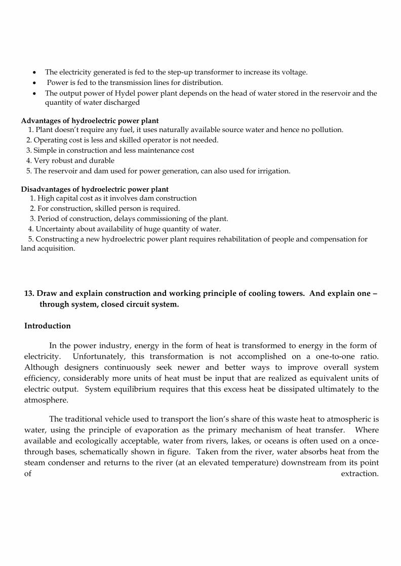
The traditional vehicle used to transport the lion’s share of this waste heat to atmospheric is
water, using the principle of evaporation as the primary mechanism of heat transfer. Where
available and ecologically acceptable, water from rivers, lakes, or oceans is often used on a once-
through bases, schematically shown in figure. Taken from the river, water absorbs heat from the
steam condenser and returns to the river (at an elevated temperature) downstream from its point
of extraction.
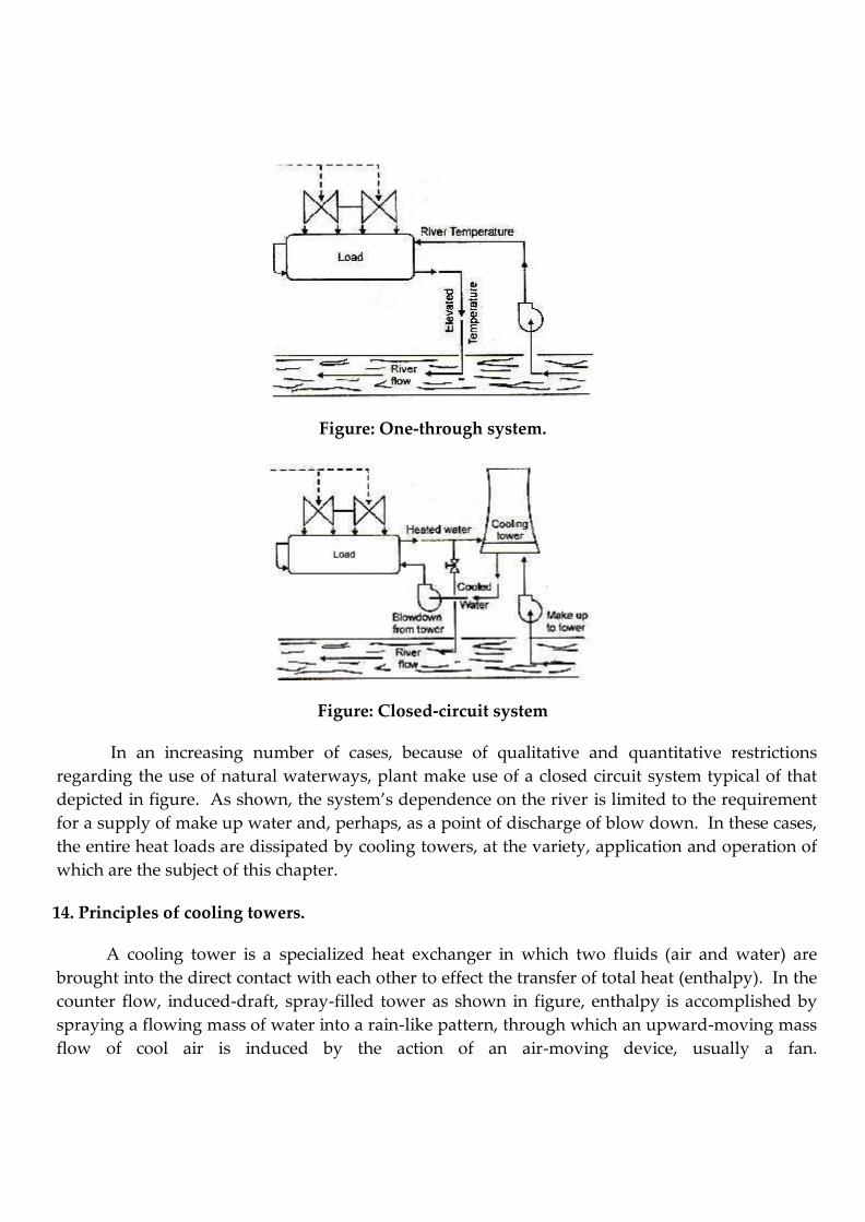
Figure: One-through system.
Figure: Closed-circuit system
In an increasing number of cases, because of qualitative and quantitative restrictions
regarding the use of natural waterways, plant make use of a closed circuit system typical of that
depicted in figure. As shown, the system’s dependence on the river is limited to the requirement
for a supply of make up water and, perhaps, as a point of discharge of blow down. In these cases,
the entire heat loads are dissipated by cooling towers, at the variety, application and operation of
which are the subject of this chapter.
14. Principles of cooling towers.
A cooling tower is a specialized heat exchanger in which two fluids (air and water) are
brought into the direct contact with each other to effect the transfer of total heat (enthalpy). In the
counter flow, induced-draft, spray-filled tower as shown in figure, enthalpy is accomplished by
spraying a flowing mass of water into a rain-like pattern, through which an upward-moving mass
flow of cool air is induced by the action of an air-moving device, usually a fan.
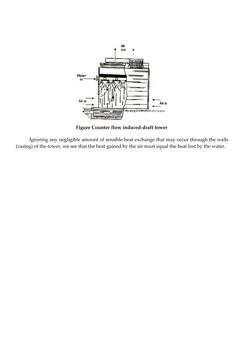
Figure Counter flow induced-draft tower
Ignoring any negligible amount of sensible heat exchange that may occur through the walls
(casing) of the tower, we see that the heat gained by the air must equal the heat lost by the water.

Catchment area
Dam and Reservoir
Draft tube
Fore bay
Surge tank