Embed Size (px)
Citation preview

UDC 629.544:629.5.015.4 Šime MALENICA1
Ivo SENJANOVIĆ2
Nikola VLADIMIR2
Hydro Structural Issues in the Design of Ultra Large Container Ships
Authors’ addresses: 1Bureau Veritas, Research Department, 67/71 Boulevard du Château, 92200 Neuilly-sur-Seine, France, e-mail: [email protected] of Zagreb, Faculty of Mechanical Engineering and Naval Architecture, Ivana Lučića 5, 10000 Zagreb, Croatia e-mail: [email protected] (Primljeno):2012-12-07 Accepted (Prihvaćeno): 2013-01-24 Open for discussion (Otvoreno za raspravu): 2014-09-30
Review paper Specific characteristic of Ultra Large Container Ships (ULCS), compared to other types of
ships, is that they are more likely to experience the hydroelastic type of structural response called springing and whipping. This is mainly due to their large dimensions, very large operational speed, and large bow flare. The evaluation of the hydroelastic response and its inclusion into the overall design procedure is significantly more complex problem than the calculation of quasi-static structural response. Classification rules are at the margin of applicability for ULCS and direct calculation is required. In this paper a review of methodology and current status of different methods and tools for structural design of ULCS is presented. Modelling of ship structure as a beam and 3D FE model for preliminary design stage and final checking is mentioned. Different fluid-structure interaction issues are considered, i.e. steady-state and dynamic response, combined with linear and nonlinear wave load. Also, development of numerical methods and software, utilizing model tests and full scale measurements, is presented. Conclusion is directed to the application of the results and the remained open questions. Keywords: full scale measurements, hydroelasticity, model tests, numerical methods, ultra large container ships Hidrostrukturni problemi u osnivanju ultravelikih kontejnerskih brodova
Pregledni rad Posebna je značajka ultravelikih kontejnerskih brodova, u odnosu na druge tipove brodova,
hidroelastični odziv u vidu pruženja i podrhtavanja, kao posljedica njihovih velikih dimenzija, otvorenoga poprečnog presjeka trupa, vrlo velike brzine u službi i velikog izboja pramca. Evaluacija hidroelastičnog odziva broda i njegovo uključenje u cjelokupni projektni postupak znatno je složeniji problem od proračuna kvazistatičkog odziva konstrukcije. Pravila klasifikacijskih društava na granici su primjenjivosti za ultravelike kontejnerske brodove i stoga se zahtijeva izravni proračun čvrstoće. U članku je prikazana metodologija i trenutačni stupanj razvoja različitih metoda za projektiranje konstrukcije ultravelikih kontejnerskih brodova. Spomenuto je modeliranje brodske konstrukcije grednim i 3D MKE modelima za preliminarno osnivanje, odnosno konačnu provjeru čvrstoće. Različite značajke međudjelovanja konstrukcije i fluida su razmotrene, tj. stacionarni i dinamički odziv, kombiniran s linearnim i nelinearnim valnim opterećenjem. Također, razmatran je razvoj numeričkih metoda i programskih alata, koristeći rezultate modelskih ispitivanja i mjerenja u naravi. Zaključak je usmjeren na primjenu rezultata i preostala otvorena pitanja. Ključne riječi: hidroelastičnost, mjerenja u naravi, modelska ispitivanja, numeričke metode, ultraveliki kontejnerski brodovi
323

1 Introduction Expansion in sea traffic is one of direct consequences of the world trade increase, and in the
last 25 years the total amount of marine trade has nearly doubled. In the same period container trade has grown approximately ten times faster, making the container fleet the fastest growing fleet at present. In 2006, the Emma Maersk went into service: it is the first of the new generation of ULCS, having a capacity to carry more than 11000 TEU. Sister ships of 18000 TEU, the so called Malacca class, are under construction in Daewoo Shipbuilding & Marine Engineering for Maersk Line. Design and construction of ULCS is challenging problem and is subject of intensive research [1].
The structural design of ULCS is driven by the economies of scale of transporting large numbers of containers in one ship and the commercial pressures of reducing the total production cost and steel weight through optimisation. Due to this increase in size, the natural frequencies of the hull girder can fall within the range of wave load excitation forces. At the same time, due to operational requirements, the cruising speed of UCLS is relatively high (approximately 27 knots) increasing the encounter frequency significantly. In addition, commercial pressures for increased availability of the ship in severe weather conditions mean that increased operational envelopes are required by the operators. Several important issues affecting ULCS have been identified: nonlinear quasi-static hydrodynamic loading, springing, slamming, green water and whipping.
Due to their inherent properties, ULCS experience quite high elastic deformations. Their structural natural frequencies are low enough for sea waves to transfer enough energy for hull girder vibration excitation. In such cases, a complete study of the interaction between the hydrodynamic environment and the elastic structure needs to be undertaken. Besides this, a complete coupling of hydrodynamic and structural models should be applied in cases where impulsive loading, such as slamming, excites transient hull vibration - whipping.
The practical procedure for ship structural design involves the verification of two main structural failure modes [2]:
• Yielding and buckling failure due to extreme event. • Fatigue initiated cracks in the structure.
These two failure modes are fundamentally different and the methodologies for their assessment are also different even if some common points exist. The final goal of the extreme event analysis is to predict, for each structural member, the single most likely worst event during whole ship life, while the goal of the fatigue analysis is to analyze the whole ship life by counting all the combinations of the stress ranges and number of cycles (S-N curves) for particular structural detail.
For the classical ships (tankers, bulk-carriers, general cargo ships …), not exceeding certain size, the usual design practice passes through the direct application of the prescribed rules and procedures issued by different Classification Societies. In the case of extreme structural response, these procedures do not involve fully direct hydro-structure calculations and the final design load cases are given in the form of the equivalent simplified load cases which are constructed as a combination of the different extreme loading conditions for assumed operating conditions. Even if the procedure for determination of the extreme loading conditions relies partially on hydrodynamic calculations, the rule approach remains basically prescriptive approach with an important part of empiricism. On the side of the structural strength, other safety coefficients are introduced and the final calibration of the rule approach is done using the extensive feedback from experience, which ensures the excellent safety record of the existing ships. Due to these calibration procedures it is not possible, in principle, to use the rule procedures for a novel designs which do not enter in the initial assumptions of the considered design (ship type, size…) and operations. As far as the fatigue life is concerned, the rule approach uses the similar equivalent load case approach which allows for very rough verification of the fatigue life.
Within the so called direct calculation approach for the assessment of the ship structural reliability, the basic idea is very simple: the structural response of the ship should be directly calculated during whole her life using the fully coupled hydro-structural models and the identification of the extreme events and fatigue life will be determined directly.
324

Since the fully consistent non-linear hydro-structure calculations are not practically possible within the reasonable combination of CPU time and accuracy, one must consider some approximate solutions using the different levels of approximation at different steps of the overall methodology. One of the main purposes of the present paper is to discuss the actual state-of-the art of different models. 2 Structural and hydrostatic models 2.1 Structural model
Hydroelastic analysis is usually performed by the modal superposition method in order to reduce CPU time. In preliminary design stage a sophisticated beam model of ship hull can be used [3]. It takes shear influence on both bending and torsion into account [3,4,5]. Influence of transverse bulkheads is included by increasing torsional stiffness of open hull segment proportionally to strain energy of the bulkhead [5,6]. Also, effective stiffness of relatively short engine room structure is incorporated in the beam model [7]. Furthermore, an advanced theory of thin-walled girders is used for determining ship cross-section properties, Figure 1 [8]. The additional stiffness parameter the shear moment of inertia is defined related to torsion in analogy with shear area in bending [3,4,5]. Reliability of the beam model is checked by comparing 1D and 3D results for natural frequencies and modes [3,5]. For illustration, Figure 2 shows the twist angle and distortion of cross-section for a pontoon with ship cross-section. Beam model is helpful for better understanding of physical behaviour of complex ship structures.
Figure 1 Warping of ship cross-section, STIFF output Slika 1 Vitoperenje poprečnog presjeka broda, izlazni rezultati programa STIFF
325

Figure 2 Pontoon deformation, lateral and top view; diagram of twist angle Slika 2. Deformacija pontona, bočni pogled i pogled odozgo; dijagram kuta uvijanja
For final analysis of ship structure a 3D FEM model of the complete structure is used.
Natural modes for free vibrations in air are determined from the eigenvalue problem ( )2ω−K M h = 0 , (1) where K is conventional stiffness matrix, M is mass matrix, ω and is natural frequency and natural mode, respectively.
h
2.2 Hydrostatic model
In ship hydroelastic analysis both conventional stiffness and restoring hydrostatic stiffness
are included. The latter is only the stiffness for rigid body modes. Determination of restoring stiffness is quite complex problem and two formulations are current today: the consistent stiffness with distributed or lumped masses, and the complete one [9,10,11,12]. The former takes ship mass directly into account, while the latter operates with geometric stiffness based on ship stress in calm sea, as result of ship weight and buoyancy distribution. Transfer functions of torsional moment determined with all three definitions of restoring stiffness are shown in Figure 3. Due to some numerical instability of the complete restoring stiffness, the consistent stiffness with distributed mass is recommended for practical use. It is determined by integration of the governing stiffness parameters and interpolated natural modes by the shape functions over area of structural finite elements and wetted panels [13].
Figure 3 Transfer function of horizontal bending moment of a barge Slika 3 Prijenosna funkcija horizontalnog momenta savijanja barže
326

3 Hydro structure interaction models Before entering into the details of the different numerical models, let us first try to classify
the different hydro-structural issues. In Table 1 the different issues are schematically separated with respect to the nature of the hydrodynamic loading and the nature of the structural response [2].
Table 1 Different hydro-structural issues Tablica 1 Različite hidro-strukturne sprege
H S LINEAR WAVE
NON LINEAR IMPULSIVE
NON LINEAR QUASI-STATIC SH11 SH12 SH13
DYNAMIC SH21 SH22 SH23
As far as the hydrodynamic loading is concerned, the usual practice is to classify it into 3 different categories:
• linear hydrodynamic loading • weakly nonlinear, non-impulsive loading • impulsive hydrodynamic loading.
Within the potential flow hydrodynamic models, which are of main concern here, the linear hydrodynamic loading means the classical linear diffraction-radiation solution also called the seakeeping hydrodynamic analysis. The weakly non-linear loading means the non-impulsive part of the wave loading which is usually covered through the different variants of the so called Froude Krylov approximation which is combined with the large ship motions. The impulsive loading includes any type of the transitory loading such as slamming, green-water, underwater explosion … In this paper slamming loading is considered only.
On the structural side the structural response can be classified into two main types: • quasi-static • dynamic (often also called hydroelastic)
There is sometime a certain misunderstanding observed in the literature regarding this separation mainly because both quasi-static and dynamic structural responses are due to the dynamic loading. However, the fundamental difference in between the quasi-static and dynamic structural response lies in the fact that the quasi-static response does not account for the structural vibrations while the hydroelastic dynamic response does.
In the following sections, the different combinations of the hydrodynamic loading and structural responses are discussed in more details. 3.1 Linear quasi-static hydro structure interactions
Linear quasi-static hydro-structure model, SH11, Table 1, represents the basis of any
subsequent hydro-structure interaction methods. This is the simplest case of hydro-structure interactions but unfortunately the problem is still open for a general case which is mainly due to the difficulties related to the solution of the seakeeping problem with forward speed.
In order to make the procedure as efficient as possible the problem is usually formulated in frequency domain which is possible due to the assumptions of linearity of both the hydrodynamic loading and structural response. This leads to the definition of the RAO’s (Response Amplitude Operators) for different ship responses (motions, internal loads, stresses…) from which the maximum response for a given operating conditions (loading condition, speed, heading & scatter diagram) can be calculated using the spectral analysis.
The good point in the case of the quasi static structural responses is that the hydrodynamic and structural calculations can be performed separately. The usual procedure passes through the solution of the rigid body diffraction-radiation problem using the Boundary Integral Equation (BIE) technique. Thanks to the linearity the problem is formulated in frequency domain and the total
327

velocity potential ϕ and corresponding hydrodynamic pressure hdp is decomposed into the incident, diffracted and 6 radiated components:
6 6
1 1
. , hdI D j Rj I D j R
j j
i p p p iϕ ϕ ϕ ω ξ ϕ ω ξ= =
= + − = + −∑ jp∑ (2)
where ω is wave frequency, jξ is response mode amplitude and 1i = − . The potential is calculated numerically using the boundary integral equation technique in
which the mean wetted body surface is discretized into a certain number of panels, Figure 4, over which the singularity distribution is assumed in a certain form (constant or higher order). Without entering into much details of the BIE procedure, let us just mention that, in the general case, the final potential can be written in the form of the singularities distribution over the mean wetted body surface . There are different types of the singularity distributions and the simplest one is based on the so called pure source distribution:
BS
( ) ( ) ( ); , (3) BS
dSϕ σ=x ξ G x ξ∬where stands for the source strength and ( )σ ξ ( );G x ξ is the Green’s function.
Figure 4 Hydrodynamic and structural mesh of the container ship Slika 4 Hidrodinamička i strukturna mreža kontejnerskog broda
Once calculated, the pressures are integrated over the mean wetted part of the body and the hydrodynamic coefficients are calculated so that the following rigid body motion equation can be written:
( )( ) ( ) ( )2 DIiω ω ω ω ω− + − + =M A B C Fξ (4)
where: genuine mass matrix of the body M ( )ωA hydrodynamic added mass matrix
( )ωB hydrodynamic damping matrix hydrostatic restoring matrix C ( )DI ωF hydrodynamic excitation vector body motion vector ξ
The solution of the motion equation gives the body motions and the seakeeping problem is formally solved.
The next step consists in transferring the loading from hydrodynamic model to the structural finite element model. This is the critical step in the procedure and should be done with greatest care in order to build fully consistent loading cases which perfectly balance the rigid body inertia and the hydrodynamic pressure loads. As far as the rigid body inertia is concerned, the situation is simple and we should just make sure that the rigid body mass matrix is evaluated using the mass distribution from the FE model.
Concerning the pressure part, the main problem comes from the fact that the hydrodynamic and structural FE meshes are usually quite different, because they were built according to very different philosophies, Figure 4. This means that an efficient procedure for pressure transfer is necessary in order to consistently apply the hydrodynamic pressure onto the structural finite
328

elements. If this step is not performed properly, the final loading case will not be balanced and the structural response will be wrong especially close to the artificial supports, which have to be included in the FE structural model for free-free types of structures such as ships.
Most of the methods, which are used in practice, employ the different interpolation schemes in order to transfer the total hydrodynamic pressure Eq. (2) from hydrodynamic model (centroids of the hydro panels) to the structural model (centroids or nodes of the finite elements).
Besides the problems of complex interpolation in 3 dimensions, it is important to note that the motion amplitudes, which are present in the definition of the total pressure, were calculated after the integration over the hydrodynamic mesh so that it is practically impossible to obtain the completely balanced structural model. This is because the FEM model has its own integration procedure which is usually very different from the one used in hydrodynamic model. In order to obtain the perfect equilibrium of the structural model we introduce here two main ideas:
• Recalculation of the pressure at the structural points, instead of interpolation • Separate transfer of the pressure components, and calculation of the hydrodynamic
coefficients (added mass, damping, hydrostatics & excitation) by integration over the structural mesh. The first point is possible thanks to the very useful property of the Boundary Integral
Equation technique which allows for the recalculation of the velocity potential at any point in the fluid as shown by Eq. (3). This makes the choice of characteristic points of the wetted structural finite elements possible and to perform the pressure integration on the FE mesh. This is important in order to make sure that the same body motions are used both for the rigid body inertia and for the re-composition of the total hydrodynamic pressure Eq. (2).
It is also important to mention that the integration of the pressures over the FEM mesh is performed using the Gauss points at the finite elements. These Gauss points are used for integration only, and have nothing to do with the Gauss points used in the theory of the structural FEM program. The accuracy of the integration can be controlled by changing the number of Gauss points per element. The pressure evaluation at the Gauss points of the FEM mesh should be done carefully. Indeed, although the BEM and FEM mesh will model the same geometry, the meshing itself can be very different. Especially at curved parts of the geometry the Gauss points at the FEM mesh will not be exactly at the BEM mesh and part of the Gauss points might fall inside the BEM mesh. This causes problems for calculation of the pressure for bodies travelling with forward speed because in that case the hydrodynamic pressure also depends on the gradient of the potential which is discontinuous across the hydrodynamic mesh. Special pre-processing of the Gauss points is thus necessary.
Finally let us also discuss one important issue related to the application of the hydrostatic restoring action which is a bit specific and sometimes misunderstood in the literature. The confusion comes from the fact that the usual practice for hydrodynamic calculations is to solve the problem in the initial earth fixed reference frame, while the structural calculations are usually done in the body fixed coordinate system. Due to the assumptions of linearity, both methods are fully correct and the possible differences are of higher order.
When calculating the linear hydrostatic restoring forces and moments, the total contribution can be separated in two parts. The first one is the same for both earth fixed and body fixed coordinate systems and concerns the change of the hydrostatic pressure due to ship motions:
13 4 5[ ( ) (hs
Gp g Y Y X Xρ ξ ξ ξ= − + − + − )]G , (5) where ( ),G GX Y are the coordinates of the ship centre of gravity. The second one depends on the coordinate system in which the motion equation is written. In the case of the earth fixed coordinate system, which is used when formulating the hydrodynamic problem, this term is associated with the change of the normal vector:
2hsp gZρ= − ×Ω n , (6)
329

where denotes the rotational component of the motion vector Ω ( )4 5, , 6ξ ξ ξ=Ω and n is unit normal vector to wetted surface. Note that this term is pressure term and should be applied on the mean wetted body surface.
In the body fixed reference frame the normal vector does not change but the gravity changes, so the term equivalent to Eq. (6) becomes:
2hsf mg= − ×Ω k , (7) where denotes the unit vector in Z direction. Note that this term is associated with the gravity forces and should be applied on each mass element of the finite element model.
k
It is possible to show that these two terms are completely equivalent [14]. Anyhow, the final loading of the FE model is composed of 3 parts
2i imω− ξ rigid body inertial loading (on each finite element)
1hd hSp p+ pressure loading (on wetted finite elements only)
im q− ×Ω k additional gravity term (on each finite element) In order to avoid the possible differences in between the pressure application in the different
FEM packages, the pressure loading is applied on the structural model in the form of the nodal forces instead of the pressures. This means that the pressure integration over the finite elements is performed in a pre-processing stage using the prescribed finite elements shape functions together with the pressure values at the FE Gauss points.
It is clear that the above structural load cases will perfectly balance pressure and inertia components because this equilibrium is implicitly imposed by the solution of the motion equation (4) in which all the different coefficients were calculated using the information from the structural FE model directly.
It is also important to mention the fact that, usually in practice, we are interested in the very local stress concentration at some particular structural details which means that the finite element model should be very refined around those details. This might lead to the prohibitive number of finite elements in the case when all these structural details are included into the global FE model. Practical way to solve this problem is based on the so called top-down procedure. This procedure consists in solving the global coarse mesh FE problem first, and in applying the coarse mesh displacements at the boundaries of the fine mesh after. In this way the fine mesh FE calculations are performed in the second step with the load cases defined by the prescribed displacements from the coarse mesh and by the local pressure and inertia of the fine mesh. Within the hydro-structure procedure presented here the implementation of the top-down procedure is rather straightforward [15].
Let us finally note that the above procedure should be performed for each operating condition (loading condition, wave frequency & heading) and for the real and imaginary part of the loading. The final results are the RAO’s of stresses in the particular structural details Figure 5. Once the RAO’s calculated, a spectral analysis is used in order to calculate the characteristic stresses (mean, significant, maximum …) in a particular sea state.
330

Figure 5 “Top-down” procedure and typical stress RAO Slika 5 „Top-down“ postupak i tipična prijenosna funkcija naprezanja 3.2 Linear hydroelastic hydro structure interactions
Depending on the ratio between the structural natural frequencies and the wave excitation
frequency, the dynamic amplification of the structural response will be more or less important. In order to calculate the dynamic amplification factor it is necessary to use the full hydroelastic coupling procedure. There are different ways to do that and in this work the so called modal approach is used. Within this approach the total ship displacement is represented as a series of different modal displacements:
( ) ( ) ( )1
, N
ii
i
x t t xξ=
= ∑H h , (8)
where ( ), x tH total displacement of one point on the body
( ) i xh modal displacements (mode shape)
( )i tξ modal amplitude. The rest of the procedure is very similar to rigid body analysis except that the number of
degrees of freedom is increased from 6 to 6 plus a certain number of elastic modes. This modal approach implies the definition of supplementary radiation potentials with the
following body boundary condition: Rj j
nϕ∂
=∂
h n . (9)
After solving the different boundary value problems for the potentials, the corresponding forces are calculated and the motion equation similar to (4) is written:
( ) 2 ( ) ( ) DIiω ω− + − + + + =m A B b k C Fξ , (10) where m is the modal structural mass, b is the structural damping, k is the structural stiffness, A is the hydrodynamic added mass, B is the hydrodynamic damping, C is the hydrostatic restoring, ξ are the modal amplitudes and DIF is the modal hydrodynamic excitation.
Contrary to the quasi-static case where the hydrodynamic pressure needs to be transferred from the hydrodynamic mesh to the structural FE mesh, in the present case, SH11, SH21, Table 1, the radiation boundary condition (9) implies the transfer of the structural modal displacements from the
331

structural mesh to the hydrodynamic mesh. Since, within the FE method, it is not possible to recalculate directly the displacements at any required point, the non-trivial interpolation procedure is necessary [16]. Typical result of this interpolation is shown in Figure 6.
Figure 6 The first natural structural mode and transfer of the modal displacements to hydrodynamic mesh Slika 6 Prvi prirodni oblik vibriranja brodske konstrukcije i prijenos modalnih pomaka na hidrodinamički model
Once the modal amplitudes have been calculated, the total stresses can be obtained, at least
theoretically, by summing the individual modal contributions and one can formally write:
( ) ( ) (1
Σ , )N
ii
i
xω ξ ω σ=
= ∑)
, (11) x
where (Σ ,x ω is the total stress, ( )i xσ is the spatial distribution of modal stresses and ( )iξ ω are the modal amplitudes. Note that rigid body modes do not contribute to the stresses.
The convergence of this series is in general very slow and it is not practically possible to include very large number of modes. As far as the dynamic amplification effects are concerned, this is not important because the main dynamic contribution to the stresses comes from the first few lowest structural modes and the rest is quasi static. In order to make the stress calculation procedure efficient, it is thus necessary to calculate the dynamic and quasi static contributions separately. The way how to perform this separation was presented in [16] and one typical example of the final stress RAO decomposition is shown in Figure 5. Finally, let us also note that the previously discussed top-down procedure for the evaluation of local stresses needs also to be adapted in order to include the dynamic amplification effects [15]. 3.3 Non-linear quasi-static and hydroelastic hydro structure interactions
In order to include the nonlinear effects into the dynamic model, the usual practice is to
work in time domain, even if some particular problems might also be solved in frequency domain using the higher order hydrodynamic theories. However, these higher order theories are not practical in the present context of calculation of the structural stresses. There are different ways of performing the time domain simulations but probably the most practical one is based on using the linear frequency domain results and transferring them into time domain following the approach proposed by Cummins [17]. It is important to note that this approach is valid for both the quasi-
332

static ship response as well as for the hydroelastic one. Indeed, the only difference is the number of degrees of freedom which is increased in the hydroelastic model.
Within this approach the motion equation is written in the following form:
( ) ( ) ( ) ( ) ( ) ( ) ( ) ( ) ( )0
t
t t t t d tτ τ τ∞+ + + − + − = +∫m A k c b K F Q&& & &ξ ξ ξ ξ t , (12)
where: m modal mass matrix
∞A infinite frequency modal added mass matrix k structural stiffness matrix C hydrostatic restoring matrix b structural damping matrix ( )t τ−K impulse response (memory) functions matrix
( )tF linear excitation force vector
( )tQ nonlinear excitation force vector
( )tξ modal body motions. It was shown in [17] that the impulse response functions can be calculated from the linear
frequency dependent damping coefficients using the following relation:
( ) ( )0
2 sin t t dω ω ωπ
∞
= ∫K B . (13)
Once the impulse response function matrix ( )tK is calculated, the motion equation (12) is
integrated in time and the nonlinear forces are added at each time step to the vector . There are various types of non-linearities which have to be included in the hydrodynamic model and it is not practically possible to account for all them.
( )tQ
Within the nonlinear effects which are believed to be particularly important in ship design, there are two main types: the first one is the Froude Krylov loading combined with large ship motions, and the second one is the strongly non-linear impulsive loading such as slamming. Note that, on the structural side, the response remains linear. 3.3.1 Weakly nonlinear hydrodynamic loading
The simplest weakly nonlinear wave loading, SHij, i = j = 1,2, Table 1, concerns the so
called Froude Krylov model which we briefly discuss here below. This model is relevant in practice both for the local fatigue loading of the side shell structural details close to the waterline, and for the modifications of the nonlinear internal loads distribution (bending moments, shear forces…).
According to the linear theory, the hydrodynamic model ”stops” at the waterline (z = 0) so that locally (close to the waterline) negative hydrodynamic pressures might occur. There are different variants of the Froude Krylov model and the simplest one is rather intuitive and consists in adding the hydrostatic part of pressure below the wave crest (in linear sense) and by putting zero total pressure above the wave trough, Figure 7. The problem basically reduces to the evaluation of the (linear) wetted part of the ship at each time step.
333

Figure 7 Linear and nonlinear hydrodynamic pressure distribution Slika 7 Linearna i nelinearna distribucija hidrodinamičkog tlaka
On hydro-structure interaction side the situation is significantly more complex when
compared to the linear case. In addition to the obvious technical difficulties (large motions, identification of wetted FE elements…), the radiation component of the loading appears to be particularly difficult to take into account. The direct application of the Cummins method implies the evaluation of the impulse response functions for every structural point, but the calculation effort to do this is huge. The approach which is chosen here is based on the use of the frequency domain radiation pressures only. This approach implies performing the hydro-structure interaction calculations as a post-processing of the seakeeping calculations because the Fourier transform on the seakeeping velocity must be done to obtain the amplitudes and phases of different frequency components. Even if these manipulations result in small numerical inaccuracies, they appear to be practically negligible for the balancing of the structural FE model. 3.3.2 Slamming & whipping
Slamming represents very important source of ship structural loading both from local and
global points of view. Very high localized pressures appear during the slamming event, and at the same time the corresponding overall forces are very high. This means that not only the local ship structure will be affected by slamming, but the whole ship will “feel” the slamming loading through the so called whipping phenomena. Whipping is defined as the transitory global ship vibrations due to slamming and one example of the typical whipping response is shown in Figure 8, where it can be clearly seen that the quasi-static loads are significantly increased by the high frequency whipping vibrations.
Figure 8 Typical full scale measurements of whipping bending moment of hull girder Slika 8 Tipični prikaz mjerenja u naravi momenta savijanja brodskog nosača uslijed podrhtavanja
334

The hydrodynamic modelling of slamming is extremely complex, SHij, i=1,2; j=1,2,3, Table 1, and still no fully satisfactory slamming model exists. However, the 2D modelling of slamming appears to be well mastered today and the 2D models are usually employed in practice. Within the potential flow approach, which is of concern here, several more or less complicated 2D slamming models exist, starting from simple von-Karman model and ending by the fully nonlinear model. In between these two models there are several intermediate ones among which is the Generalized Wagner Model (GWM) first introduced in [18]. The GWM allows for evaluation of the impact pressure along the arbitrary ship cross-section and for arbitrary penetration velocity.
Integration of the 2D GWM slamming model into the overall hydroelastic model is not trivial and strong coupling is required at each time step. Indeed, the overall relative velocity of each section is determined from the global mathematical dynamic model (12) and is used as an input for the GWM through an iterative procedure. Due to the 2D assumption of the GWM, the practical procedure to include 3D effects passes through the so-called strip approach where the part of the ship (usually bow and stern) is cut into several strips each of them being considered separately from the slamming point of view, as shown in Figure 9.
Figure 9 Strip subdivision of bow for slamming calculations Slika 9 Vrpčasta diskretizacija pramca za proračun udaranja o valove
The GWM provides the impact pressure along the ship section and this pressure is
integrated over the overall FE model using the following relation:
1
s
j
Ni i
j j j j jj L
p b dl=
= ∑∫F h n , (14)
where is the slamming load projected on the i-th mode, iF jp is the slamming pressure on the
section j and are the mode shape i, normal vector and width of the section j respectively. ij j jbh n
Due to the separate slamming calculations for each strip, the non-trivial interpolation procedures in space and time are necessary in order to properly transfer the impact pressure onto the global FE model of the ship.
Compared to the well-known original Wagner model, which represents the reference for the impact problems, the GWM allows accounting for the exact body geometry. The price to pay is that the Boundary Value Problem for velocity potential at each penetration depth should be solved numerically. This leads to a very significant increase of the overall CPU time for whipping calculations. In order to reduce the CPU time, it is possible to use the property of the GWM solution which allows for the separation of different slamming pressure components in the following form:
( ) ( ) ( ) ( )2( ) , ,v wp t P t P tς η ς ς η ς= +& && , (15)
335

where ( )tς is the relative penetration depth and is the transversal coordinate on the ship section. This fact allows for pre-calculating the sectional slamming characteristics and to use the
look-up tables for interpolation of slamming pressures and forces for the instantaneous penetration depth. In this way the CPU time can be significantly saved.
One example of the typical whipping numerical simulations obtained using the present method is shown in Figure 10.
Figure 10 Typical numerical simulations of whipping bending moment Slika 10 Tipična numerička simulacija momenta savijanja uslijed podrhtavanja 4 Design methodologies – WILS project
As mentioned in the introduction, the basic idea of the direct approach should be very
simple: the structural response of the ship will be directly calculated during whole her life and the identification of the extreme events and fatigue life will be determined directly. There are two main difficulties which need to be resolved before being able to proceed in this way:
• Modelling difficulties (numerical or experimental), • Choice of the representative operating conditions.
Both issues are equally important. The difficulties related to the pure hydro-structure modelling issues were discussed in the previous sections and here below we briefly discuss and comment the difficulties related to the choice of the representative operating conditions.
In order to ensure consistency of design methodology, the most important point is, probably, the choice of the ship operational profile which needs to be done in as reasonable way as possible. Indeed, we do not know in advance in which real conditions the ship will operate, but the ship owner usually requires the possibility to operate worldwide, which means that the methodology should take into account the fact that the ship will encounter the most extreme wave events existing in all the oceans worldwide. At the same time, we should keep in mind that the operating conditions do not mean the sea state definition only and the sea state should always be associated to the ship loading conditions, wave heading and ship’s speed. How the ship master will operate the ship in particular sea conditions is a big question. Not every ship master will choose the same decisions and all possible decisions should be taken into account in order to cover the most critical cases. The feedback from the ship operations clearly shows that the sister ships do not experience the same fatigue life consumptions on the same sailing route, when operated by different people. How this should be taken into account?
The usual practice is to fix in advance some combinations of speeds and headings that are chosen in rather empirical way, which unfortunately appears to be “too empirical” and not very logical in some cases. At the same time, the most common choice of the worst sea states is the so called North Atlantic scatter diagram also recommended by the IACS. The problem is that, if we apply directly these operating conditions within the direct calculation approach (based either on numerical simulations or on model tests) the extreme design parameters (bending moments, shear forces, torsional moments, accelerations…), which are obtained at the end of this procedure, usually significantly exceed the prescribed IACS values at a given probability level [19]. We should mention however that this fact is not necessarily very critical in practice because we count with the fact that the assumed operating conditions are too severe and there are other safety factors which are introduced when considering the ship structural resistance. The proof that the existing procedures are not “too bad” is the excellent safety record of the existing ship fleet. However, we should be very careful when applying the same procedures for novel designs which exceed the
336

limits of the classical ship designs. One of such cases is the Ultra Large Container Ship concept which significantly exceeds the initial assumptions about the ship size and structural flexibility. In particular, and as mentioned in the introduction, the structural natural frequencies of these ships are very low which, combined with a relatively high speed, can give rise to the important hydroelastic contributions to the structural response both from extreme and fatigue points of view. Knowing all the difficulties which we have to properly account for the quasi-static part of the response already, we can easily imagine how difficult will be to take consistently the hydroelastic effects into account. Additional important difficulty is related to the numerical modelling and that not only from the accuracy point of view but also because of the sometimes very extreme CPU time requirements. Indeed, even if we accept the above discussed numerical models to be good enough, the associated computational effort is huge and it is not practically possible to perform very long time numerical simulations for arbitrary operating conditions. The same problem is also related to model tests.
For the time being, due to all the mentioned difficulties related to both the modelling and operational issues, the usual direct (or strictly speaking “quasi direct”) calculation procedures passes through the definition of the equivalent design waves, equivalent design wave episodes, equivalent design sea states and in some cases (whipping) through the long term direct calculations combined with some additional assumptions. A state-of-the art overall methodology for direct calculation approach is presented in [20] and interesting discussions on hydroelastic contribution are given in [21].
The real question we should ask ourselves is: how much are we far from the reality, both in our initial assumptions and in our models? Unfortunately, the actual state of the art does not allow for giving fully clear answer to this question. Significant work on the subject is undertaken within many research projects worldwide and here below we discuss a few of them.
One of these projects is the WILS (Wave Induced Loads on Ships) project led by MOERI (Maritime & Ocean Research Institute), Daejeon, Korea, in which the model tests of an ultra large container ship flexible model were conducted in different operating conditions. The project aims at producing a useful database for the validation of numerical models and at the same time at providing the ship’s design data. The WILS project was initiated by MOERI and was attended by the major Korean shipyards (DSME, SHI, HHI, STX & Hanjin), major classification societies (BV, ABS, DNV, LR, KR, NK & GL) and Seoul National University.
Several measurement campaigns were performed by MOERI within the first 2 phases and the 3rd phase is in preparation for the next year. The experimental model was an elastically scaled beam type model and is shown in Figure 11. A few significant results of comparisons between the numerical results provided by BV and the experimental results are shown in Figure 12 [22].
337
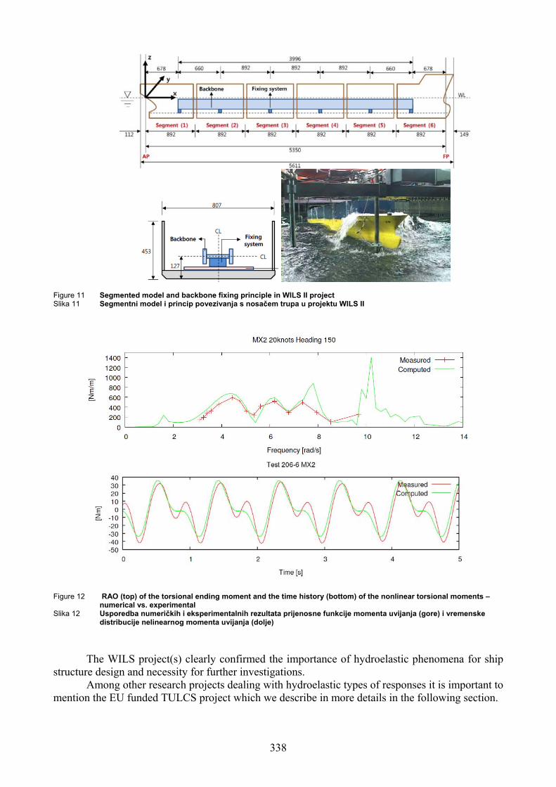
Figure 11 Segmented model and backbone fixing principle in WILS II project Slika 11 Segmentni model i princip povezivanja s nosačem trupa u projektu WILS II
Figure 12 RAO (top) of the torsional ending moment and the time history (bottom) of the nonlinear torsional moments – numerical vs. experimental
Slika 12 Usporedba numeričkih i eksperimentalnih rezultata prijenosne funkcije momenta uvijanja (gore) i vremenske distribucije nelinearnog momenta uvijanja (dolje)
The WILS project(s) clearly confirmed the importance of hydroelastic phenomena for ship
structure design and necessity for further investigations. Among other research projects dealing with hydroelastic types of responses it is important to
mention the EU funded TULCS project which we describe in more details in the following section.
338

5 TULCS project In 2009 a dedicated European project within FP7 was initiated with the intention to bring
more light onto the above discussed issues. The project was named TULCS (Tools for Ultra Large Container Ships) and the Consortium of the following 13 partners was composed: Bureau Veritas (BV) as coordinator, Marin, Compagnie Maritime d'Affrètement – Compagnie Générale Maritime (CMA-CGM), Canal de Experiencias Hidrodinamicas (CEHIPAR), Ecole Centrale Marseille (ECM), Technical University Delft (TUD), University of Zagreb (UZ), Technical University of Denmark (DTU), University of East Anglia (UEA), SIREHNA, WIKKI, HYDROCEAN, Brze Vise Bolje (BVB). In addition, the world biggest shipyard Hyundai Heavy Industry (HHI) is also participating in the project as a joint partner.
The project combines the numerical methods, model tests and full scale measurements within a dedicated methodology for analysis and exploitation of the results. On the numerical side the accent is put on the potential flow based numerical solvers even if the CFD methods are included in order to evaluate their practical applicability to these problems. Each critical part of the overall technical problem is considered within the dedicated Work Package (WP). The project is decomposed into the following working packages:
WP2 - Identification of the real operating conditions WP3 - Global quasi-static wave loading & responses WP4 - Global hydro-elastic loading & responses WP5 - Local hydrodynamic loading & responses - slamming WP6 - Model tests WP7 - Full scale measurements WP8 - Analysis and development of the rational design methodology. Detailed description and organization of the project is given in [23] and [24]. Here, the
activities are briefly summarized. The case study is the 9200 TEU ULCS Rigoletto owned by CMA-CGM and built by HHI. It
was very important to have the detailed design of the same ship for all the developments (numerical, experimental and full scale), which allowed for consistent analysis and exploitation of the different results. Within the WP2 special attention was given to the identification of the real operating conditions (CMA-CGM) and of the design requirements (HHI). A dedicated questionnaire was sent to more than 40 ship masters and useful information about the ship operational profile was collected (CMA-CGM). In the WP3 different developments of the numerical seakeeping methods for the case with forward speed (the problem still open) were undertaken (MARIN, BV and TUD). Practical tools were developed and coupled with the 3D FE structural models. In the WP4 an efficient procedure for hydroelastic coupling with a simplified non-uniform beam model and a full 3D FE model was developed and coupled with the seakeeping tools (BV & UNIZAG). Different, potential flow based, slamming models (2D and 3D) were developed in the WP5 (UEA, MARIN, ECM) and, at the same time, the CFD calculations were performed by SPH and VOF numerical methods (HYDROCEAN & WIKKI). The methodologies for their integration into the overall hydroelastic seakeeping tool in time domain were developed and their implementation is ongoing. In the WP6 two types of model tests were performed: ECM did the simplified hydroelastic model tests on a hyper-elastic body while CEHIPAR performed a large number of experiments on the elastic and rigid model of the Rigoletto for various operating conditions. Extensive full scale instrumentation (motion inertial unit, accelerometers, local and global strain gauges, wave radar system for sea state measurements…) was installed onboard the Rigoletto and useful data were collected (MARIN & Sirehna), Figure 13.
339

Figure 13. Schematic presentation of measuring points on the container ship Rigoletto Slika 13. Shematski prikaz mjernih točaka na kontejnerskom brodu Rigoletto
The analysis and comparisons of the different sorts of results are ongoing in the WP8 and the overall methodology for design is discussed (BV, DTU, UNIZAG, BVB). Within the project a special attention was given to the development of the practical user friendly tool which would include the project major developments and which could be used by the design engineers in their daily practice. This final TULCS tool was built by BVB within the BV HOMER hydro-structural framework, Figure 14.
Figure 14 Overall computation scheme of HOMER software Slika 14 Opći proračunski prikaz programskog paketa HOMER
It is worthwhile mentioning that during preparation and within the Project several doctoral
theses were completed [25,26,27,28]. They are related to developing of the beam model, consistent restoring stiffness and mathematical modelling of hydro-structure interaction, with significant contributions.
Within the TULCS project, the 1st International Workshop on Springing & Whipping [29] was organized and was open to the Institutions outside of the project. The workshop was very well attended, by all the actors from the shipbuilding process (classification societies, shipyards, ship operators, research institutes, universities…), and useful information was collected and used for
340

better identification of the project developments and project objectives. The 2nd Workshop, coinciding with the official end of the TULCS project, was held in Split from 8 to 10 of November 2012.
All aspects of the ULCS design were discussed and there were in total 31 lectures presented within the following sections:
1. General 2. Real life & uncertainties 3. Design methodologies 4. Seakeeping 5. Model tests 6. Full scale measurements 7. TULCS 8. Slamming 9. Hydroelastic beam model. Worldwide experts from the field attended the Workshop among them: W.G. Price, O.M.
Faltinsen, R. Riggs, J.J. Jensen, A.A. Korobkin, I. Senjanovic and many others, Figure 15. Participants from classification societies (Bureau Veritas, Lloyd's Register and Croatian Register of Shipping) gave the indications how these effects should be included into the design procedures in a rational way based on direct calculation procedures. The participants from the major Korean shipyards (HHI & DSME) gave to the workshop a very practical value and certitude that the tools and results which were discussed will be directly incorporated into the future ship designs. An interesting presentation was given by the Captain Igor Sikic who is the ship master on a 13300 TEU Container Ship. Indeed, the feedback from the real operational experience is extremely important for the success of the design methods based on the direct calculation approach where the use of realistic operating conditions is essential. Let us also mention an important participation of the University of Zagreb within the team of Prof. Senjanovic. A list of presentations is given in the Appendix together with the group photo of the participants.
6 Conclusions
The main purpose of the paper is to briefly present the state-of-the art and needs in structural
design of ultra large container ships, and the realized contribution through the Project TULCS. Hence, the different hydro-structural issues in ship design in the context of so-called direct
calculation procedures are discussed. Special accent was put on springing and whipping hydroelastic effects.
It is fair to say that the modelling of springing and whipping is still a challenge and that there is no fully satisfactory numerical tool able to deal with these issues consistently. At the same time, the other available tools such as model tests and full scale measurements have their own drawbacks (high cost, limited number of the covered cases, representatives of the beam model…) so that no definite opinion can be made on this subject for the moment. Anyhow, it seems to be clear that more attention should be given to these issues in the near future because there is clear evidence (numerical, model tests and full scale) that these hydroelastic types of structural responses exist and that their effects can be quite important both for fatigue and extreme response issues. In addition, the analysis of some recent accidents indicates that the whipping and springing are likely to be, at least partially, the reason for the structural failure.
It is important to note that, even without the inclusion of the hydroelastic effects, the classical quasi-static hydro-structure interactions are also not perfectly mastered today and their inclusion into the design procedures still appears not to be fully satisfactory. This is true both for the imperfections of the deterministic hydro-structure calculation models and (even more) for the overall methodology for their inclusion (representative sea states, operational conditions, probability levels…).
341

Figure 15 Participants of the 2nd International Workshop on Springing and Whipping of Ships Slika 15 Sudionici Druge radionice o pruženju i podrhtavanju broda
Finally, let us also mention one very important point which might become very important in the near future and which concerns the compatibility of the rule based approach and the direct calculation approach. Indeed, it would be reasonable to expect that the two approaches should give the same answer (yes or no) in terms of the acceptance of the particular ship structural design. However, due to the quite different background of the two approaches, it seems to be very hard to ensure the compatibility of the two approaches in the general case.
All this means that more research work will be necessary in the future in order to consistently assess all hydro-structure interaction phenomena, and to include them into the ship design procedures in a more rational way. Following the results and conclusions obtained within the WILS, TULCS and some other research projects not mentioned here, an important initiative on the continuation of the research on hydro-structure interactions was initiated by the Pusan National University under the support of the National Research Foundation of Korea within the GCRC-SOP (Global Core Research Centre – Ship and Offshore Plant). Bureau Veritas and University of Zagreb are actively participating in this project and their role is to further improve the methods and methodologies for the evaluation of hydro-structure interactions in seakeeping.
Acknowledgements The achievements presented in this paper are result of investigation supported by the European Commission under the FP7 Sustainable Surface Transport (SST), through the Project Tools for Ultra Large Container Ships (TULCS), SST-2008-RTD-1-234146 and this support is greatly acknowledged. The authors also acknowledge the support of the National Research Foundation of Korea (NRF) grant funded by the Korean Government (MEST) through GCRC-SOP (Grant No. 2011-0030670). Finally, the authors express their gratitude to the project partners and the workshop participants for their valuable contributions.
342

References
[1] Proceedings of International Conference on Design and Operation of Container Ships, RINA, London, 2008.
[2] MALENICA, Š., DERBANNE, Q.: “Hydro-elastic issues in the design of ultra large container ships – TULCS project”, Proceedings of the 6th International Conference on Hydroelasticity in Marine Technology, Tokyo, Japan, 2012, p. 233-246.
[3] SENJANOVIĆ, I., TOMAŠEVIĆ, S., VLADIMIR, N.: “An advanced theory of thin-walled girders with application to ship vibrations”, Marine Structures, Vol. 22, No. 3, 2009, p. 387-437.
[4] SENJANOVIĆ, I., RUDAN, S., VLADIMIR, N.: “Influence of shear on the torsion of thin-walled girders”, Transactions of FAMENA, Vol. 33, No. 2, 2009, p. 35-50.
[5] SENJANOVIĆ, I., VLADIMIR, N., CHO, D.S.: “Application of 1D FEM & 3D BEM hydroelastic model for stress concentration assessment in large container ships”, Brodogradnja, Vol. 63, No. 4, 2012, p. 307-317.
[6] SENJANOVIĆ, I., TOMAŠEVIĆ, S., RUDAN, S., SENJANOVIĆ, T.: “Role of transverse bulkheads in hull stiffness of large container ships”, Engineering Structures, Vol. 30, No. 9, 2008, p. 2492-2509.
[7] SENJANOVIĆ, I., VLADIMIR, N., TOMIĆ, M.: “Effective stiffness of the engine room structure in large container ships”, Brodogradnja, Vol. 62, No. 1, 2011, p. 15-27.
[8] …“STIFF”, User's Manual. FAMENA, Zagreb, 2011. [9] SENJANOVIĆ, I., VLADIMIR, N., TOMIĆ, M.: “Formulation of consistent restoring stiffness
in ship hydroelastic analysis”, Journal of Engineering Mathematics, Vol. 72, No. 1, 2012, p. 141-157.
[10] HUANG, L.L., RIGGS, H.R.: “The hydrostatic stiffness of flexible floating structure for linear hydroelasticity”, Marine Structures, Vol. 13, 2000, p. 91-106.
[11] SENJANOVIĆ, I., HADŽIĆ, N., TOMIĆ, M.: “Investigation of restoring stiffness in the hydroelastic analysis of slender marine structures”, Journal of Offshore Mechanics and Arctic Engineering, ASME, August 2011, Vol. 133/031107-1.
[12] SENJANOVIĆ, I., HADŽIĆ, N., VLADIMIR, N.: “Restoring stiffness in the hydroelastic analysis of marine structures”, Brodogradnja, Vol. 62., No. 3, 2011, p. 265-279.
[13] SENJANOVIĆ, I., HADŽIĆ, N., BIGOT, F.: “Finite element formulation of different restoring stiffness issues in the ship hydroelastic analysis and their influence on response”, Ocean Engineering, Vol. 59, 2013, p. 198-213.
[14] MALENICA, Š.: “Some aspects of hydrostatic calculations in linear seakeeping“, Proceedings of the 14th NAV Conference, Palermo, Italy, 2003.
[15] SIRETA, F.X., DERBANNE, Q., BIGOT, F., MALENICA, Š., BAUDIN, E.: “Hydroelastic response of a ship structural detail to seakeeping loads using a top-down scheme”, Proceedings of the 31st OMAE Conference, Rio de Janeiro, 2012.
[16] MALENICA, Š., TUITMAN, J.T., BIGOT, F., SIRETA, F.X., ”Some aspects of 3D linear hydroelastic models of springing“, International Conference on Hydrodynamics, Nantes, France, 2008.
[17] CUMMINS, W.E.: “The impulse response function and ship motions”, Schiffstecknik, 1962. [18] ZHAO, R., FALTINSEN, O.M., AARSENS, J.V.: “Water entry of arbitrary two dimensional
section with and without flow separation”, The 21st Symposium on Naval Hydrodynamics, 1996.
[19] PARUNOV, J., ĆORAK, M.: “Influence of environmental and operational uncertainties on wave bending moments of containerships”, William Froude Conference: Advances in Theoretical and Applied Hydrodynamics – Past and Future, RINA, Portsmouth, UK, 2010, p. 201-207.
343

[20] Bureau Veritas, NR583 - Methodology for direct hydro-structure calculations including springing and whipping, 2012.
[21] DERBANNE, Q., SIRETA, F.X., BIGOT, F., DE-HAUTECLOCQUE, G.: “Discussion on hydroelastic contribution to fatigue damage of containerships”, Proceedings of the 6th International Conference on Hydroelasticity in Marine Technology, Tokyo, Japan, 2012, p. 377-388.
[22] BIGOT, F., DERBANNE, Q., SIRETA, F.X., MALENICA, Š., TUITMAN, J.T.: “Global hydroelastic ship response, comparison of numerical model and WILS model tests”, Proceedings of ISOPE Conference, Hawaii, USA, 2011.
[23] MALENICA, Š., SENJANOVIĆ, I., DERBANNE, Q., VLADIMIR, N.: “On the EU FP7 Project: Tools for Ultra Large Container Ships – TULCS”, Brodogradnja, Vol. 62, No. 2, 2011, p. 177-187.
[24] SENJANOVIĆ, I., VLADIMIR, N., TOMIĆ, M., HADŽIĆ, N., MALENICA, Š.: “Some aspects of structural modelling and restoring stiffness in hydroelastic analysis of large container ships”, Ships and Offshore Structures, accepted for publication, 2013, DOI:10.1080/17445302.2012.762728.
[25] TOMAŠEVIĆ, S.: “Hydroelastic model of dynamic response of container ships in waves”, Ph.D. Thesis, University of Zagreb, Zagreb, 2007.
[26] TUITMAN, J.: “Hydroelastic response of ship structures to slamming induced whipping”, Ph.D. Thesis, TU Delft, Zagreb, 2010.
[27] VLADIMIR, N.: “Hydroelasticity and fatigue strength of large container ships”, Ph.D. Thesis, University of Zagreb, Zagreb, 2011.
[28] HADŽIĆ, N.: “Restoring stiffness in hydroelastic analysis of ship structures”, Ph.D. Thesis, University of Zagreb, Zagreb, 2012.
[29] MALENICA, Š., DERBANNE, Q., SENJANOVIĆ, I.: “Proceedings of the 1st Int. Workshop on Springing & Whipping of Ships”, Dubrovnik, Croatia, 2010. (http://www.fsb.unizg.hr/tulcs/).
Appendix – List of Workshop Lectures 1. Hydro structural issues in the design of ultra large container ships - TULCS Project
S. Malenica, Bureau Veritas, France 2. Theoretical prediction of springing and whipping excitation of ships
O.M. Faltinsen, Norwegian University of Science & Technology NTNU, Norway 3. Feasibility study on structural design of an Ultra Large Containership larger than 20,000 TEU
class B.K. Choi, Hyundai Heavy Industries, South Korea
4. Operation of ULCS – real life I. Sikic, CMA CGM, Croatia
5. Fatigue assessment based on measurement campaign onboard a very large containership M. Renaud, CMA CGM, France
6. Influence of aging on ultimate strength of the ships of Shipping, Croatia P. Jurisic, Croatian Register
7. “As-built” strength of ships K. Ziha, University of Zagreb, Croatia
8. t Structural reliability of ULCS – the concepJ. Parunov, University of Zagreb, Croatia
9. reme wave-induced responses in ships Stochastic procedures for extJ.J. Jensen, DTU, Denmark
10. ydroelastic response Direct calculations methodologies for hQ. Derbanne, Bureau Veritas, France
11. ontainer ships Fast parametric rolling simulations of c
344

A. Turk, University of Rijeka, Croatia 12. thod for seakeeping problems with forward speed
13. ping and springing of a large container ship IOST, South Korea
14.
measurements
20. e container ships determined by different
LCS developments
ulate whipping loads he Netherlands
UK
etagne, France
imulation of slamming impacts
l models nce
31. hipping effects and design assessment of Ultra Large Container Ships . Lee, Lloyd's Register, UK
On Rankine-Kelvin Hybride meI. Ten, Bureau Veritas, France Experimental investigation of torsion whipS.Y. Hong, MOERI, K
A. Marón, CEHIPAR, Spain Flexible model tests
15. tests and full scale M. Schiere, MARIN, The Netherlands Validation of TULCS tool with model
16. tate estimation J. Raymond, Sirehna, France Full scale measurements: sea s
17. Modal parameter estimation of ship global modes D. Dessi, INSEAN-CNR, Italy
18. Full scale measurements on 9200 TEU container vessel s J. Koning, MARIN, The Netherland
19. Validation of hydro-elastic whipping prediction using full scale measurements J. Tuitman, TNO, The Netherlands
nse of largComparative analysis of hydroelastic respoformulations of restoring stiffness in FEM technique
a N. Hadzic, University of Zagreb, Croati21. Nonlinear hydro-elastic model in time domain – TU
J. De Lauzon, Bureau Veritas, France 22. Approximate method to calc
G.K. Kapsenberg & M. Schiere, MARIN, T23. Working with TULCS tool
S. Bralic, Brze Vise Bolje d.o.o., Croatia 24. A model of body exit from water
A.A. Korobkin, University of East Anglia,25. Some aspects of oblique water entry for 3D bodies
Y.M. Scolan, ENSTA - Br26. On the approximation of the slamming force on 2D ship-like sections
S. Seng, DTU, Denmark 27. From validation to application of the SPH-flow solver for the s
N. Couty, Hydrocean, France 28. Transient impact response based on Timoshenko beam theory
H.R. Riggs, University of Hawaii, USA 29. Hydroelastic analysis of large container ships by beam structural model
N. Vladimir, University of Zagreb, Croatia 30. on tool for both beam and 3D FEM structuraUnified hydroelastic simulati
. Bigot, Bureau Veritas, FraFWY
345