Embed Size (px)
Citation preview

-1-
HYDRO-TOWER 100ODEON
100
IN-WALL TANK
INSTALLATION INSTRUCTIONS
/K-6284T-W/K-6285T/K-77666TK-6283T/K-8854T
K-6284T
�
�
�
�
�
�
�
Read installation guide in illustration and word filecarefully, and install the tank according to instructions inthe guide to avoid product damage and installationinconvenience caused by inappropriate operation.
All data contained is based upon the last productinformation available at the time of publication. KohlerCompany reserves the right to implement changes ofproduct characteristics, packaging and availability at anytime without further notice.
Do not apply erosive cleanser and solvent in the tank,which will damage tank spares and result in leakage in thetank. Kohler will not be responsible for any damagerelated to above mentioned cleanser or solvent.
Do not apply spares that are not provided by Kohler, andplease note that glass adhesive tape shall not be appliedto the installation of Kohler spares. Kohler will not beresponsible for any damage related to installation withspares not provided by Kohler.
Water temperature 1 C~45 C, Environmental Temperature
1 C~55 C.
Min water supply:0.02MPa(dynamic pressure),Max watersupply:0.74MPa(static pressure).
This product complies with GB26730-2011.
o o
o o
�
�
�
�
�
�
�
�
�
1 C~45 C 1 C~55 C
:0.02MPa( ), :0.74MPa()
GB26730-2011
o o o o
3/6 100
( ) ...............................................................K-6284T
3/4.5 100
( )...........................................................K-6284T-W
( )........................K-6285T
6 ....................................K-77666T
( ) ......................................K-6283T
( ) ......................................K-8854T
Ordering Information
3/6L HYDRO-TOWER 100 In-Wall Tank
(With Frame)...............................................................K-6284T
3/4.5L HYDRO-TOWER 100 In-Wall Tank
(With Frame) ..........................................................K-6284T-W
ODEON In-Wall Tank(Without Iron Rack) ..................K-6285T
ODEON In-wall Tank 6L W/O Frame........................K-77666T
RATIO In-Wall Tank Faceplate(Not Supplied)............K-6283T
BEVEL In-Wall Tank Faceplate(Not Supplied) ...........K-8854T
�
�
�
�
�
(K-6284T) 3/6L(K-6284T-W) 3/4.5L(K-6285T) 7.7 0.2L(K-77666T) 6L
K-6285T/K-77666T /
Function Explanation
�
�
�
�
�
Anti flow-backwards
Adjustment of inlet water level
Adjustment of flushing volume
Single/double gear
Assemble, disassemble and maintenance can be donewithout tools
flushingWater usage (K-6284T): 3/6LWater usage (K-6284T-W): 3/4.5LWater usage (K-6285T): 7.7 0.2LWater usage (K-77666T): 6LK-6285T/K-77666T Same water usage for both small/bigpush buttons
©
©
Copyright Kohler China Investment Co., Ltd. 2017
2017
KOHLER CHINA INVESTMENT CO., LTD NO.158, JIANG CHANG SAN ROAD,JING'AN DISTRICT, SHANGHAI, PRC POST CODE: 200436
( ) 158 200436
1316549-T01-A
-2-
�
�
�
�
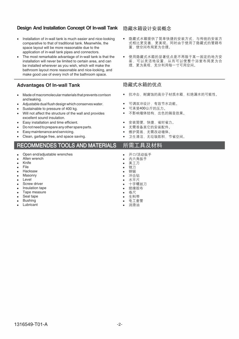
Installation of in-wall tank is much easier and nice-looking
comparative to that of traditional tank. Meanwhile, the
space layout will be more reasonable due to the
application of in-wall tank pipes and connectors.
The most remarkable advantage of in-wall tank is that the
installation will never be limited to certain area, and can
be installed wherever as you wish, which will make the
bathroom layout more reasonable and nice-looking, and
make good use of every inch of the bathroom space.
Design And Installation Concept Of In-wall Tank
�
�
�
�
�
�
�
�
400
Advantages Of In-wall Tank
�
�
�
�
�
�
�
�
Sustainable to pressure of 400 kg.
Will not affect the structure of the wall and provides
excellent sound insulation.
Easy installation and time efficient.
.
.
Clean, garbage free, and space .
Made ofmacromolecular materials thatprevents corrison
and leaking.
Adjustable dual flush design which conserves water.
Do notneed toprepare any other spare parts
Easymaintenance and servicing
saving
RECOMMENDES TOOLS AND MATERIALSRECOMMENDES TOOLS AND MATERIALS
�
�
�
�
�
�
�
�
�
�
�
�
�
Open end/adjustable wrenchesAllen wrenchKnifeFileHacksawMasonryLevelScrew driverInsulation tapeTape measureSeal tapeBushingLubricant
�
�
�
�
�
�
�
�
�
�
�
�
�
/
1316549-T01-A
-3-
05/7/13
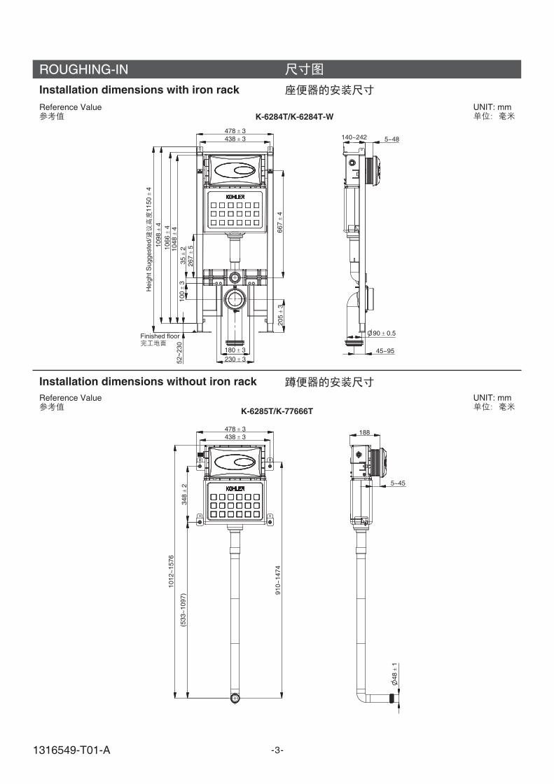
ROUGHING-IN
UNIT: mm
Installation dimensions with iron rack
Installation dimensions without iron rack
UNIT: mm
Reference Value
Reference Value
K-6284T/K-6284T-W
K-6285T/K-77666T
Finished floor
Heig
htS
uggeste
d/
1150
4
478 3
478 3
348
2
438 3
438 3
667
4
1098
4
35
2100
3
205
3
180 3
90 0.5
48
1
230 352~
230
267
51066
41048
4
140~242 5~48
45~95
188
5~45
1012~
1576
910~
1474
(533~
1097)
1316549-T01-A
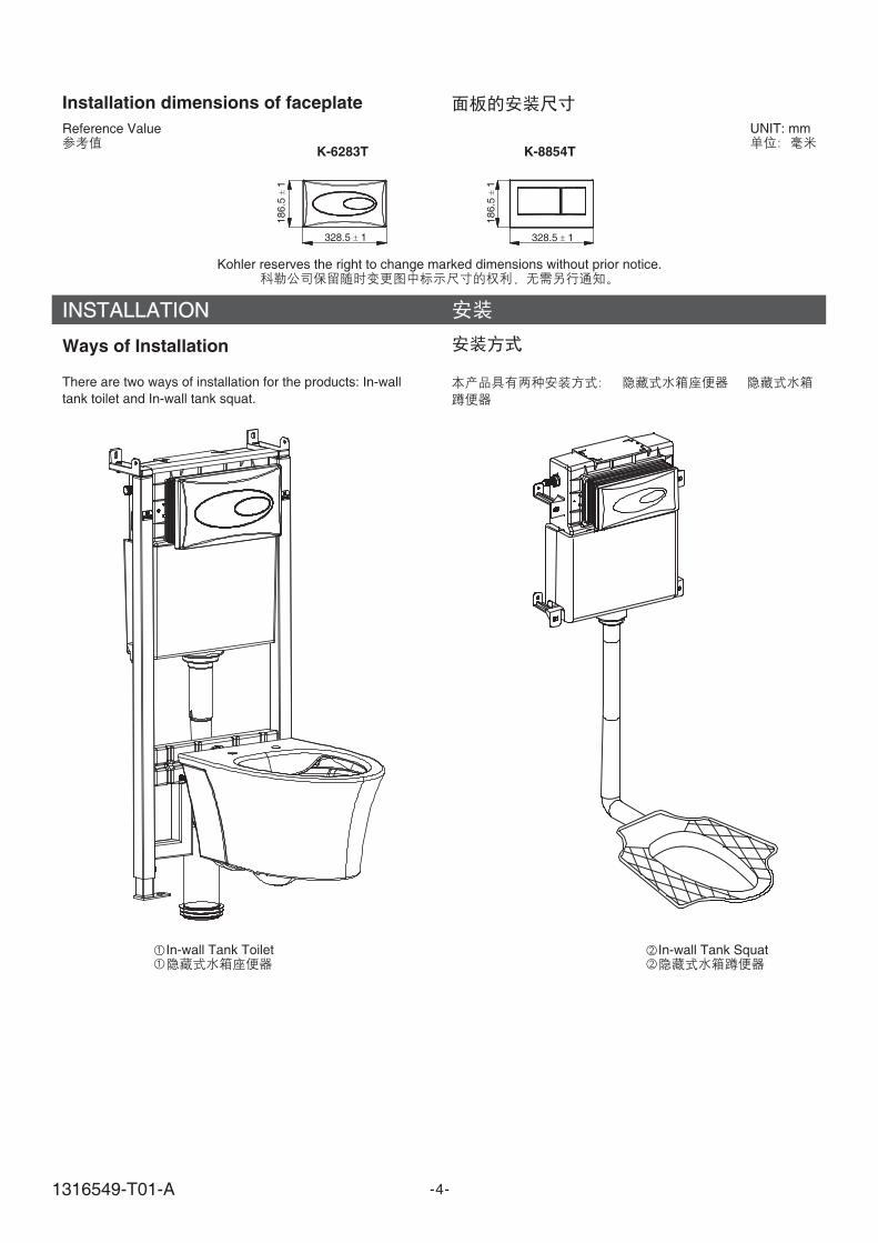
INSTALLATION
Ways of Installation
There are two ways of installation for the products: In-wall
tank toilet and In-wall tank squat.
In-wall Tank Squat
-4-
In-wall Tank Toilet
Installation dimensions of faceplate
UNIT: mmReference Value
Kohler reserves the right to change marked dimensions without prior notice.
328.5 1 328.5 1
186.5
1
186.5
1
K-6283T K-8854T
1316549-T01-A

Installation for In-wall Tank Toilet
A. Installation of In-wall Tank
1. Loose hex-head screw and adjust mounting bracket heightas shown in Fig A.Loose hex-head screw and adjust supporting feet height asshown in Fig B.
mounting bracket and supporting feet shall be adjustedper customer ideal height. Use leveler to ensure the balanceof steel bracket.
Note:
A.
1. A
B
-5-
Screw
MediumAllen Key
AdjustableBracket
A
B
Screw
Hex-headWrenchMounting
Bracket
2. Drill four holes with diameter of 10mm and depth of 80mmwith churn drilling as shown.A. Fill the bulge nail into the instruction hole on the wall, fix
the fixing frame to the bulge nail, adjust the gasket andtighten the nut.
B. Fill the bulge nail into the instruction hole, fix theadjustable bracket to the bulge nail, adjust the gasketand tighten the nut.
2. A B 10mm 80mm
A.
B.
Adjustable Bracket
MountingBracket
A
B
Bulge Screw
Bulge Screw
GasketGasket
Nut
Nut
1316549-T01-A
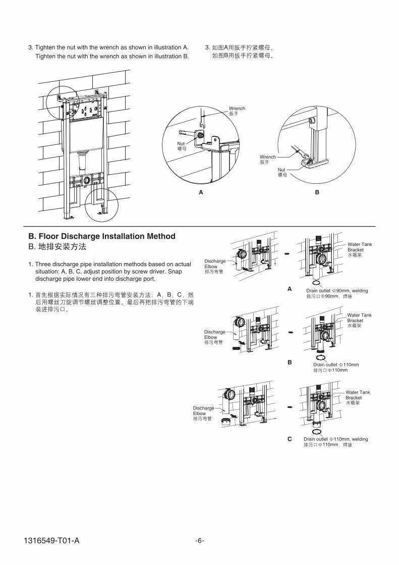
B. Floor Discharge Installation Method
B.
1. Three discharge pipe installation methods based on actual
situation: A, B, C, adjust position by screw driver. Snap
discharge pipe lower end into discharge port.
1. A B C
B
C
A
DischargeElbow
DischargeElbow
DischargeElbow
Water TankBracket
Water TankBracket
Water TankBracket
Drain outlet 90mm, welding90mm
Drain outlet 110mm110mm
Drain outlet 110mm, welding110mm
-6-
3. A
B
3. Tighten the nut with the wrench as shown in illustration A.
Tighten the nut with the wrench as shown in illustration B.
A B
Nut
Wrench
Nut
Wrench
1316549-T01-A
-7-
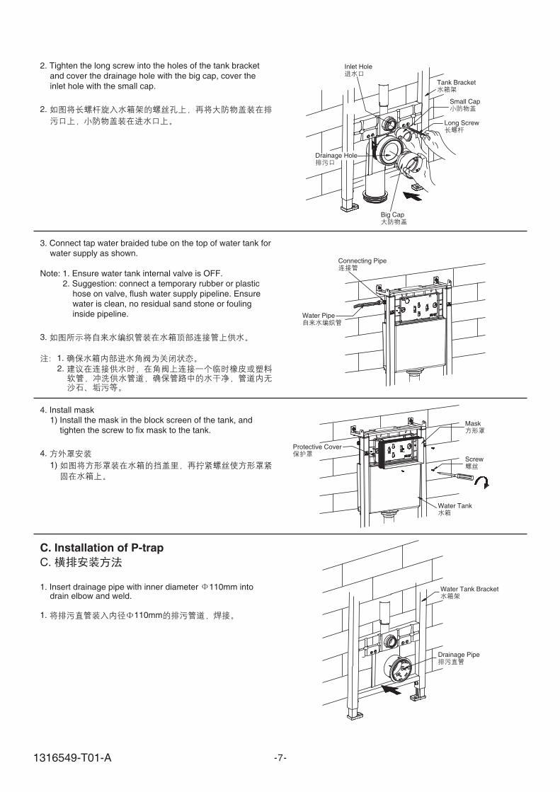
2. Tighten the long screw into the holes of the tank bracket
and cover the drainage hole with the big cap, cover the
inlet hole with the small cap.
2.
Inlet Hole
Drainage Hole
Big Cap
Tank Bracket
Small Cap
Long Screw
3. Connect tap water braided tube on the top of water tank forwater supply as shown.
Note: 1. Ensure water tank internal valve is OFF.2. Suggestion: connect a temporary rubber or plastic
hose on valve, flush water supply pipeline. Ensurewater is clean, no residual sand stone or foulinginside pipeline.
3.
1.
2.
Water Pipe
Connecting Pipe
Mask
Screw
Water Tank
Protective Cover
4. Install mask1) Install the mask in the block screen of the tank, and
tighten the screw to fix mask to the tank.
4.
1)
C. Installation of P-trap
C.
1. Insert drainage pipe with inner diameter 110mm intodrain elbow and weld.
1. 110mm
Water Tank Bracket
Drainage Pipe
1316549-T01-A

2. Tighten the long screw into the holes of the tank bracket
and cover the drainage hole with the big cap, cover the
inlet hole with the small cap.
2. Long Screw
Inlet Hole
Drainage Hole
Big Cap
Tank Bracket
Small Cap
3. When finishing the brickwork of the wall, take out the big
and small caps, and eliminate unwanted mask with a sharp
knife.
3.
1. Install the inlet pipe and outlet pipe to the lavatory asshown, and mark on the pipes at the back side of the tankwith a ruler and a pencil, and reserve appropriate spaceaccording to the distance from the back of the tank to theoutlet hole on the wall.
1.
Mask
Big Cap
Small Cap
Inlet Pipe
Outlet ipeP
-8-
D. Installation of Toilet
D.
1316549-T01-A
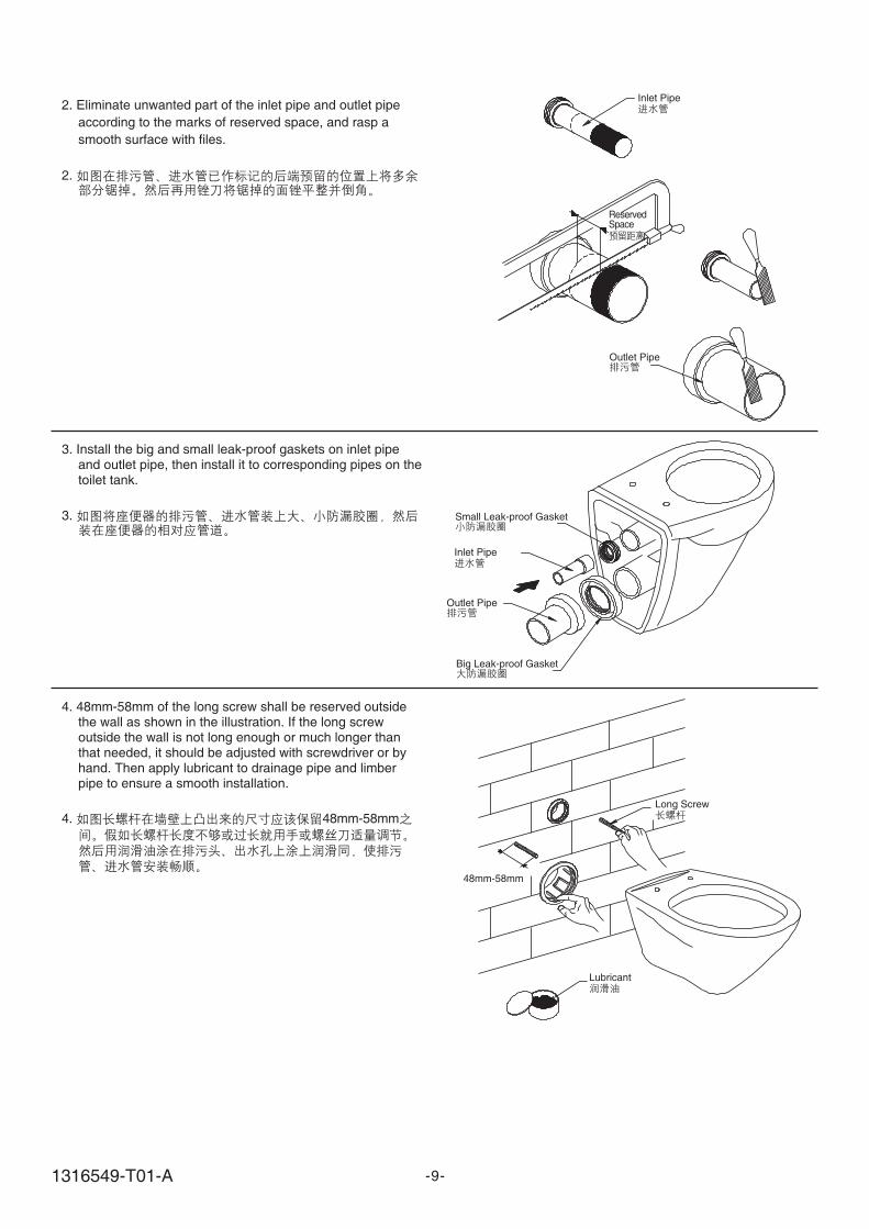
2. Eliminate unwanted part of the pipe and outlet pipe
according to the marks of reserved space, and rasp a
smooth surface with files.
inlet
2.
Inlet Pipe
ReservedSpace
Outlet ipeP
-9-
3. Install the big and small leak-proof gaskets on inlet pipeand outlet pipe, then install it to corresponding pipes on thetoilet tank.
3. Small Leak-proof Gasket
Inlet Pipe
Outlet ipeP
Big Leak-proof Gasket
4. 48mm-58mm of the long screw shall be reserved outsidethe wall as shown in the illustration. If the long screwoutside the wall is not long enough or much longer thanthat needed, it should be adjusted with screwdriver or byhand. Then apply lubricant to drainage pipe and limberpipe to ensure a smooth installation.
4. 48mm-58mmLong Screw
Lubricant
48mm-58mm
1316549-T01-A
-10-
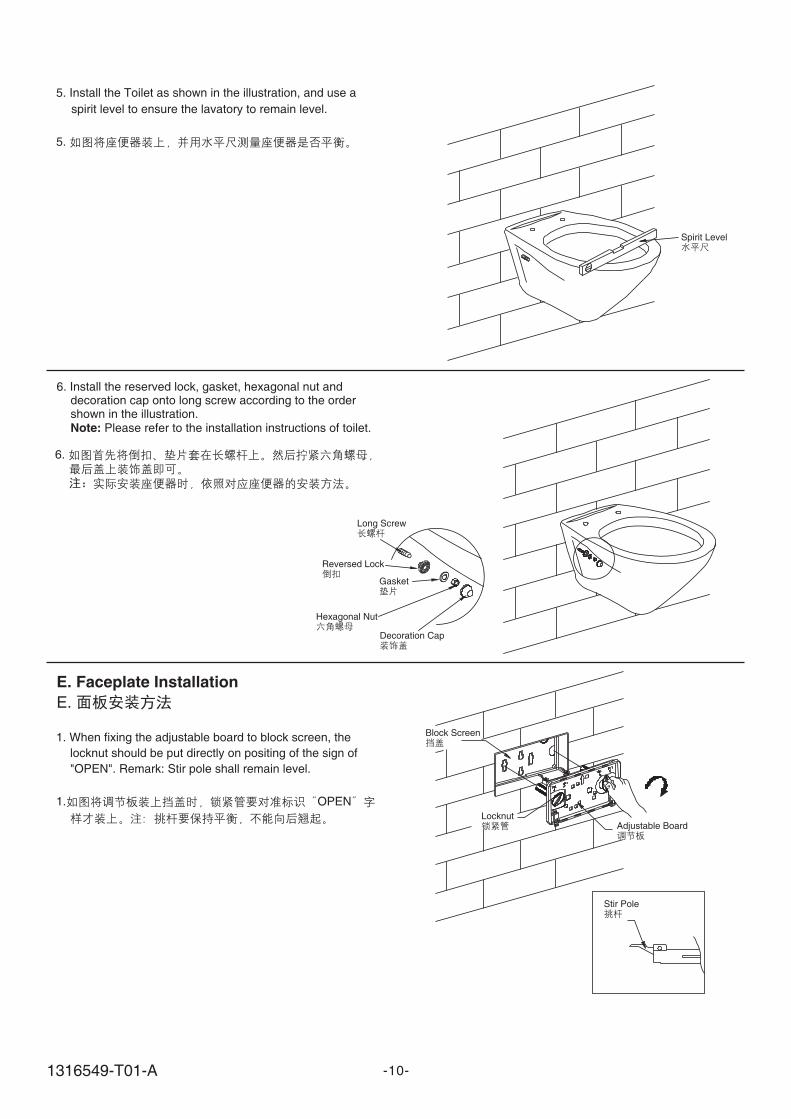
1. When fixing the adjustable board to block screen, the
locknut should be put directly on positing of the sign of
OPEN . Remark: Stir pole shall remain level." "
1. OPEN
Block Screen
LocknutAdjustable Board
Stir Pole
Gasket
Long Screw
Reversed Lock
Hexagonal Nut
Decoration Cap
6. Install the reserved lock, gasket, hexagonal nut anddecoration cap onto long screw according to the ordershown in the illustration.
Please refer to the installation instructions of toilet.Note:
6.
5. Install the Toilet as shown in the illustration, and use a
spirit level to ensure the lavatory to remain level.
5.
Spirit Level
E. Faceplate Installation
E.
1316549-T01-A

2. Fix the adjustable board on the wall by tightening the
locknut as shown in the illustration. And the locknut should
be directly put on the position of the sign of
LOCK . (Indications are marked on the adjustable board,
please refer to indications in installation)
" "
2.
LOCK (
)
3. Install the faceplate as shown in the illustration. Put the
lock on the faceplate directly on the reversed lock on
adjustable board, then push the faceplate and lock it. The
installation shall begin from bottom to top.
3.
4. In-wall tank toilet is ready to be put into use.
4.
Lock
Adjustable Board
Reversed Lock
Faceplate
Adjustable Board
Locknut
Full FlushButton Half Flush
Button
-11-
Finished Installation Illustration
1316549-T01-A

Installation for In-wall Tank Squat
A. Installation of In-wall Tank
1. Mark on the wall for appropriate position for fixing bracket,and drill four holes with diameter of 10mm and depth of80mm with churn drilling as shown in illustration, and fill inthe holes with bulge screw and tighten the screw to set thefixing bracket.
Note: Ensure the fixing bracket to remain level.
A.
1.
10mm 80mm
Screw
-12-
O
Fixing Bracket
Bulge Screw
Gasket
Spring
Nut
2. Put the tank onto the fixing bracket as shown in the right
figure and adjust the tank to level . Then tighten screws
with hex-head key. Note: it is a must to keep the tank level.
Connect the inlet hose with tank inlet pipe.
Note: 1. Ensure water tank internal valve is OFF.
2. Suggestion: connect a temporary rubber or plastic
hose on valve, flush water supply pipeline. Ensure
water is clean, no residual sand stone or fouling
inside pipeline.
2.
1.
2.
Level
Tank
TightenLoosen
Medium Allen Key
Connecting Pipe
Water Pipe
1316549-T01-A

3. Install the mask in the block screen of the tank, and tighten
the screw to fix the mask to the tank.
3.
4. Fix the leak-proof gasket to syphon as shown in illustration,
and adjust the syphon to appropriate position to be fixed to
the infall of squat.
4.
5. When finishing the brickwork, eliminate unwanted part of
the mask.
5.
Mask
Leak-proof Gasket
Syphon
Sharp Knife
Screw
Mask
-13-
Block Shield
1316549-T01-A
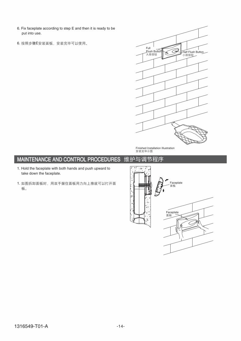
6. Fix faceplate according to step E and then it is ready to be
put into use.
1. Hold the faceplate with both hands and push upward to
take down the faceplate.
1.
6. E
FullFlush Button Half Flush Button
MAINTENANCE AND CONTROL PROCEDURESMAINTENANCE AND CONTROL PROCEDURES
Finished Installation Illustration
Faceplate
Faceplate
-14-1316549-T01-A
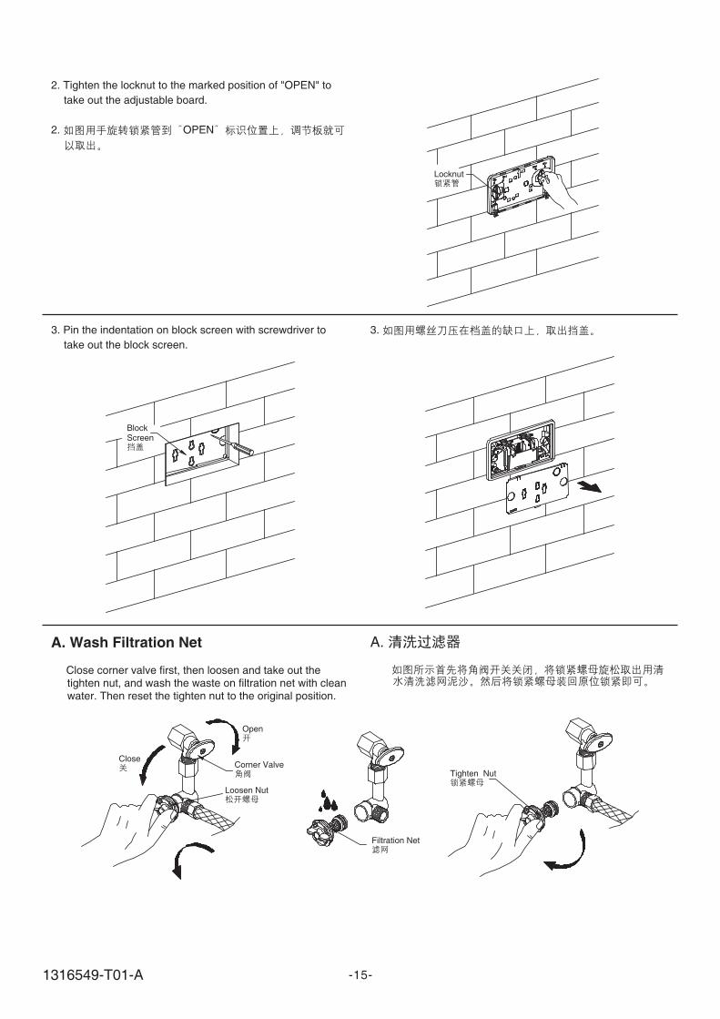
2. Tighten the locknut to the marked position of OPEN to
take out the adjustable board.
" "
2. OPEN
Locknut
3. Pin the indentation on block screen with screwdriver to
take out the block screen.
3.
BlockScreen
A. Wash Filtration Net
Close corner valve first, then loosen and take out thetighten nut, and wash the waste on filtration net with cleanwater. Then reset the tighten nut to the original position.
A.
Open
CloseCorner Valve
Tighten Nut
Filtration Net
Loosen Nut
-15-1316549-T01-A
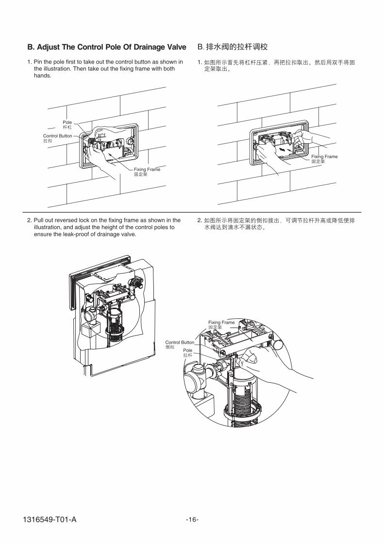
B.
1.
B. Adjust The Control Pole Of Drainage Valve
1. Pin the pole first to take out the control button as shown inthe illustration. Then take out the fixing frame with bothhands.
Pole
Control Button
Fixing Frame
2. Pull out reversed lock on the fixing frame as shown in the
illustration, and adjust the height of the control poles to
ensure the leak-proof of drainage valve.
2.
-16-
Fixing Frame
Fixing Frame
Control Button
Pole
1316549-T01-A
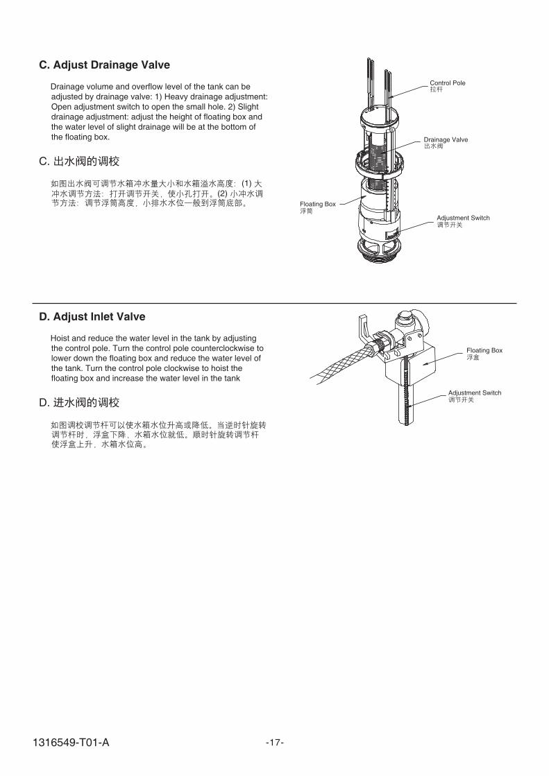
D. Adjust Inlet Valve
Hoist and reduce the water level in the tank by adjusting
the control pole. Turn the control pole counterclockwise to
lower down the floating box and reduce the water level of
the tank. Turn the control pole clockwise to hoist the
floating box and increase the water level in the tank
D.
C. Adjust Drainage Valve
Drainage volume and overflow level of the tank can be
adjusted by drainage valve: 1) Heavy drainage adjustment:
Open adjustment switch to open the small hole. 2) Slight
drainage adjustment: adjust the height of floating box and
the water level of slight drainage will be at the bottom of
the floating box.
C.
(1)
(2)
Control Pole
Drainage Valve
Adjustment Switch
Floating Box
-17-
Floating Box
Adjustment Switch
1316549-T01-A
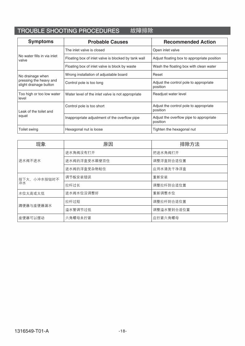
TROUBLE SHOOTING PROCEDURESTROUBLE SHOOTING PROCEDURES
No water fills in via inletvalve
The inlet valve is closed Open inlet valve
Floating box of inlet valve is blocked by tank wall Adjust floating box to appropriate position
Floating box of inlet valve is block by waste Wash the floating box with clean water
Wrong installation of adjustable board Reset
Control pole is too long Adjust the control pole to appropriateposition
Water level of the inlet valve is not appropriate
No drainage whenpressing the heavy andslight drainage button
Too high or too low waterlevel
Leak of the toilet andsquat
Symptoms Probable Causes Recommended Action
Control pole is too short
Inappropriate adjustment of the overflow pipe
Toilet swing Hexagonal nut is loose
Readjust water level
Adjust the control pole to appropriateposition
Adjust the overflow pipe to appropriateposition
Tighten the hexagonal nut
-18-1316549-T01-A


![Roman odeon en[1]](https://img.pdfslide.net/doc/110x75/557e9f8cd8b42a1d048b535c/roman-odeon-en1.jpg)


![Roman odeon el[1]](https://img.pdfslide.net/doc/110x75/557ea10dd8b42ac5658b47dc/roman-odeon-el1.jpg)