Embed Size (px)
Citation preview

1Revision date: 12.08.16
STK# DIMENSIONS
113541 202" W x 39" H x 144" L*
*Dimensions have been rounded and are approximate.Frame only. Does not include NFT channels or drain plumbing.
Designed to grow healthy plants without soil using mineral-nutrient solutions.
©2016 Growers SupplyAll Rights Reserved. Reproduction is prohibited without permission.
HydroCycle 6" Pro NFT Lettuce Systems
2 Revision date: 12.08.16
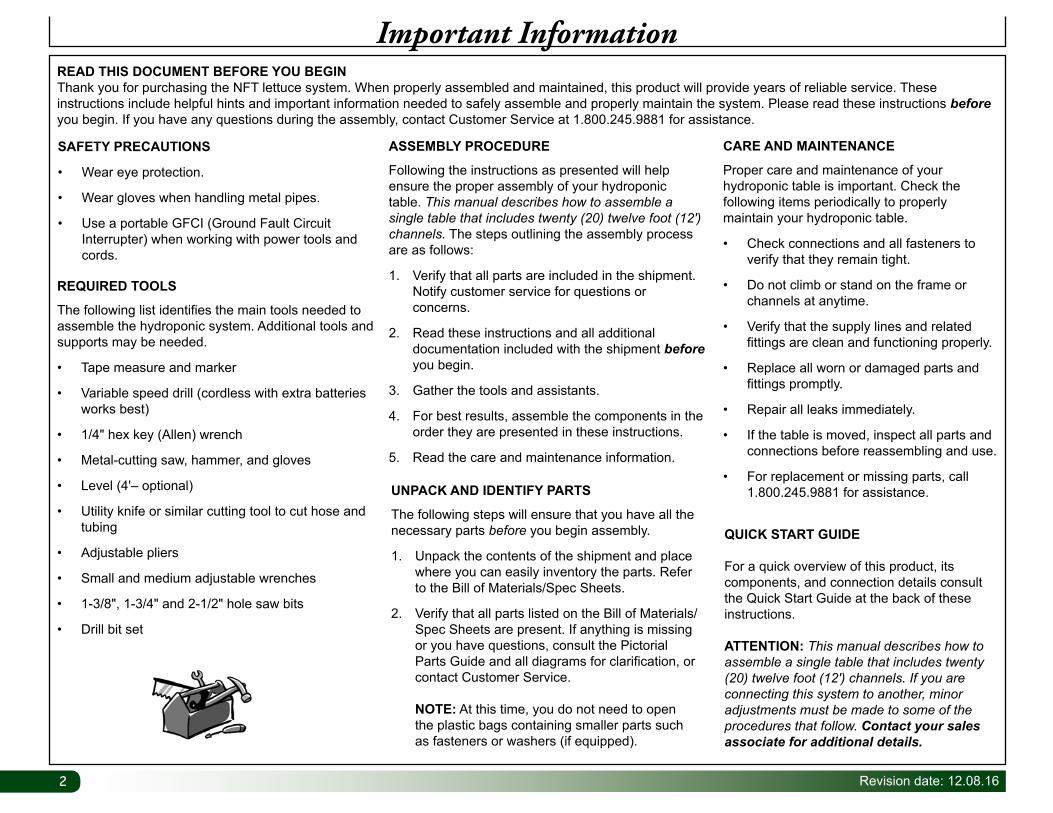
READ THIS DOCUMENT BEFORE YOU BEGINThank you for purchasing the NFT lettuce system. When properly assembled and maintained, this product will provide years of reliable service. These instructions include helpful hints and important information needed to safely assemble and properly maintain the system. Please read these instructions before you begin. If you have any questions during the assembly, contact Customer Service at 1.800.245.9881 for assistance.
ASSEMBLY PROCEDURE
Following the instructions as presented will help ensure the proper assembly of your hydroponic table. This manual describes how to assemble a single table that includes twenty (20) twelve foot (12') channels. The steps outlining the assembly process are as follows:
1. Verify that all parts are included in the shipment. Notify customer service for questions or concerns.
2. Read these instructions and all additional documentation included with the shipment before you begin.
3. Gather the tools and assistants.
4. For best results, assemble the components in the order they are presented in these instructions.
5. Read the care and maintenance information.
CARE AND MAINTENANCE
Proper care and maintenance of your hydroponic table is important. Check the following items periodically to properly maintain your hydroponic table.
• Check connections and all fasteners to verify that they remain tight.
• Do not climb or stand on the frame or channels at anytime.
• Verify that the supply lines and related fittings are clean and functioning properly.
• Replace all worn or damaged parts and fittings promptly.
• Repair all leaks immediately.
• If the table is moved, inspect all parts and connections before reassembling and use.
• For replacement or missing parts, call 1.800.245.9881 for assistance.
Important Information
SAFETY PRECAUTIONS
• Wear eye protection.
• Wear gloves when handling metal pipes.
• Use a portable GFCI (Ground Fault Circuit Interrupter) when working with power tools and cords.
UNPACK AND IDENTIFY PARTS
The following steps will ensure that you have all the necessary parts before you begin assembly.
1. Unpack the contents of the shipment and place where you can easily inventory the parts. Refer to the Bill of Materials/Spec Sheets.
2. Verify that all parts listed on the Bill of Materials/Spec Sheets are present. If anything is missing or you have questions, consult the Pictorial Parts Guide and all diagrams for clarification, or contact Customer Service.
NOTE: At this time, you do not need to open the plastic bags containing smaller parts such as fasteners or washers (if equipped).
QUICK START GUIDE For a quick overview of this product, its components, and connection details consult the Quick Start Guide at the back of these instructions.
ATTENTION: This manual describes how to assemble a single table that includes twenty (20) twelve foot (12') channels. If you are connecting this system to another, minor adjustments must be made to some of the procedures that follow. Contact your sales associate for additional details.
REQUIRED TOOLS
The following list identifies the main tools needed to assemble the hydroponic system. Additional tools and supports may be needed.
• Tape measure and marker
• Variable speed drill (cordless with extra batteries works best)
• 1/4" hex key (Allen) wrench
• Metal-cutting saw, hammer, and gloves
• Level (4'– optional)
• Utility knife or similar cutting tool to cut hose and tubing
• Adjustable pliers
• Small and medium adjustable wrenches
• 1-3/8", 1-3/4" and 2-1/2" hole saw bits
• Drill bit set
3Revision date: 12.08.16
Important Information
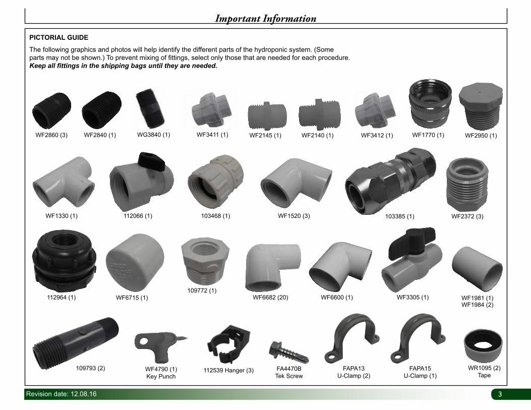
PICTORIAL GUIDE
The following graphics and photos will help identify the different parts of the hydroponic system. (Some parts may not be shown.) To prevent mixing of fittings, select only those that are needed for each procedure. Keep all fittings in the shipping bags until they are needed.
112964 (1) WF6715 (1)
109793 (2)
109772 (1)WF6682 (20) WF6600 (1)
WF2372 (3)WF1330 (1) 112066 (1) 103468 (1) WF1520 (3) 103385 (1)
WF2860 (3) WF2840 (1) WG3840 (1) WF3411 (1) WF2145 (1) WF2140 (1) WF1770 (1)WF3412 (1) WF2950 (1)
WF3305 (1) WF1981 (1)WF1984 (2)
FAPA15U-Clamp (1)
FAPA13U-Clamp (2)
WR1095 (2)Tape
WF4790 (1)Key Punch
FA4470BTek Screw
112539 Hanger (3)
4 Revision date: 12.08.16
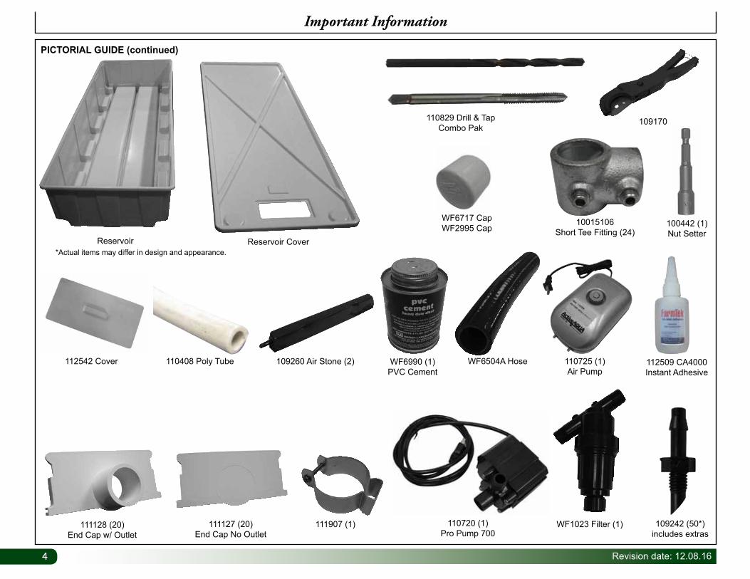
109260 Air Stone (2)
111128 (20)End Cap w/ Outlet
110720 (1)Pro Pump 700
110725 (1)Air Pump
111127 (20)End Cap No Outlet
WF1023 Filter (1)
WF6990 (1)PVC Cement
10015106Short Tee Fitting (24)
110408 Poly Tube112542 Cover WF6504A Hose
PICTORIAL GUIDE (continued)
Important Information
Reservoir*Actual items may differ in design and appearance.
Reservoir Cover
100442 (1)Nut Setter
109242 (50*)includes extras
112509 CA4000 Instant Adhesive
109170110829 Drill & Tap Combo Pak
WF6717 CapWF2995 Cap
111907 (1)
5Revision date: 12.08.16
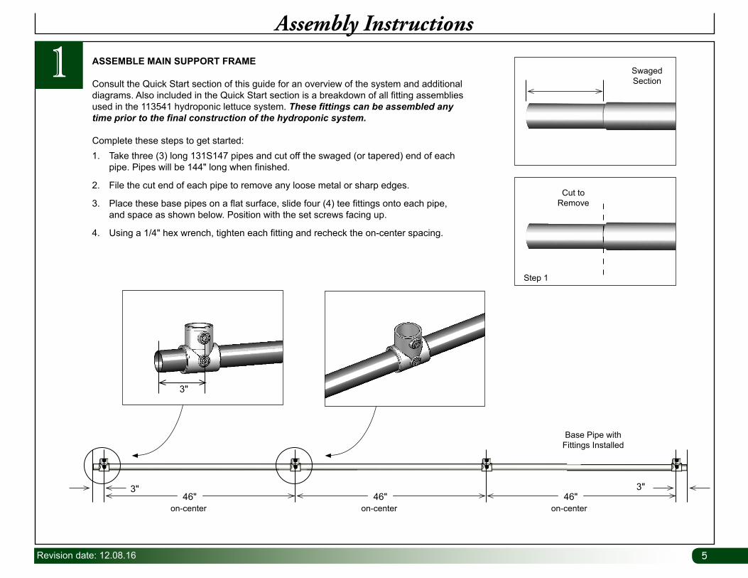
Base Pipe with Fittings Installed
on-center on-center on-center
3"
3" 3"46" 46" 46"
1Assembly Instructions
1. Take three (3) long 131S147 pipes and cut off the swaged (or tapered) end of each pipe. Pipes will be 144" long when finished.
2. File the cut end of each pipe to remove any loose metal or sharp edges.
3. Place these base pipes on a flat surface, slide four (4) tee fittings onto each pipe, and space as shown below. Position with the set screws facing up.
4. Using a 1/4" hex wrench, tighten each fitting and recheck the on-center spacing.
ASSEMBLE MAIN SUPPORT FRAME
Consult the Quick Start section of this guide for an overview of the system and additional diagrams. Also included in the Quick Start section is a breakdown of all fitting assemblies used in the 113541 hydroponic lettuce system. These fittings can be assembled any time prior to the final construction of the hydroponic system.
Complete these steps to get started:
Cut to Remove
Step 1
Swaged Section
66 Revision date: 12.08.16
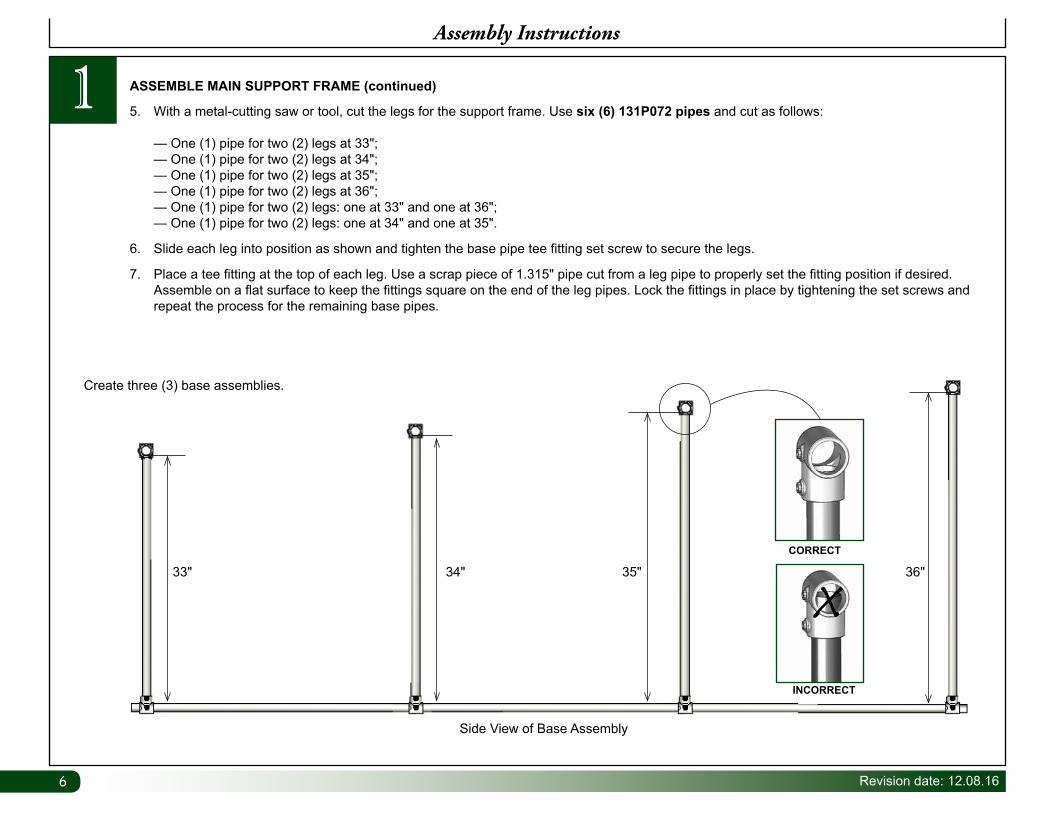
5. With a metal-cutting saw or tool, cut the legs for the support frame. Use six (6) 131P072 pipes and cut as follows: — One (1) pipe for two (2) legs at 33"; — One (1) pipe for two (2) legs at 34"; — One (1) pipe for two (2) legs at 35"; — One (1) pipe for two (2) legs at 36"; — One (1) pipe for two (2) legs: one at 33" and one at 36"; — One (1) pipe for two (2) legs: one at 34" and one at 35".
6. Slide each leg into position as shown and tighten the base pipe tee fitting set screw to secure the legs.
7. Place a tee fitting at the top of each leg. Use a scrap piece of 1.315" pipe cut from a leg pipe to properly set the fitting position if desired. Assemble on a flat surface to keep the fittings square on the end of the leg pipes. Lock the fittings in place by tightening the set screws and repeat the process for the remaining base pipes.
ASSEMBLE MAIN SUPPORT FRAME (continued)1
Side View of Base Assembly
INCORRECT
CORRECT
33" 34" 35" 36"
Assembly Instructions
Create three (3) base assemblies.
7Revision date: 12.08.16
21" to center of leg pipe
Leg
A
Ground Level
202" Cross Support
80"On-Center
80"On-Center
Leg
End View of Support Frame
AStep 13
FA4470B
Assembly Instructions
1 ASSEMBLE MAIN SUPPORT FRAME (continued)
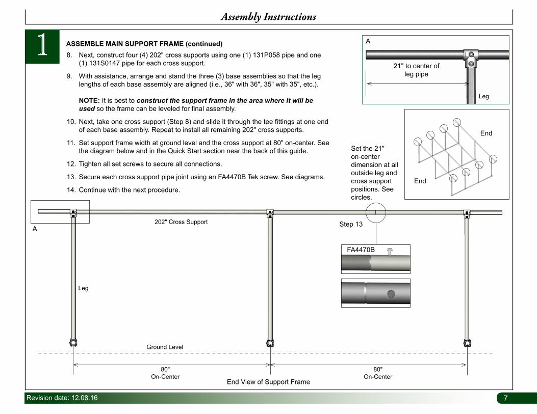
Set the 21" on-center dimension at all outside leg and cross support positions. See circles.
End
End
8. Next, construct four (4) 202" cross supports using one (1) 131P058 pipe and one (1) 131S0147 pipe for each cross support.
9. With assistance, arrange and stand the three (3) base assemblies so that the leg lengths of each base assembly are aligned (i.e., 36" with 36", 35" with 35", etc.). NOTE: It is best to construct the support frame in the area where it will be used so the frame can be leveled for final assembly.
10. Next, take one cross support (Step 8) and slide it through the tee fittings at one end of each base assembly. Repeat to install all remaining 202" cross supports.
11. Set support frame width at ground level and the cross support at 80" on-center. See the diagram below and in the Quick Start section near the back of this guide.
12. Tighten all set screws to secure all connections.
13. Secure each cross support pipe joint using an FA4470B Tek screw. See diagrams.
14. Continue with the next procedure.
88 Revision date: 12.08.16
Assembly Instructions
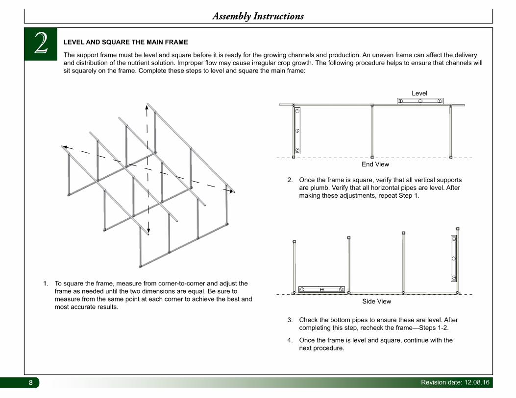
2 LEVEL AND SQUARE THE MAIN FRAME
The support frame must be level and square before it is ready for the growing channels and production. An uneven frame can affect the delivery and distribution of the nutrient solution. Improper flow may cause irregular crop growth. The following procedure helps to ensure that channels will sit squarely on the frame. Complete these steps to level and square the main frame:
1. To square the frame, measure from corner-to-corner and adjust the frame as needed until the two dimensions are equal. Be sure to measure from the same point at each corner to achieve the best and most accurate results.
2. Once the frame is square, verify that all vertical supports are plumb. Verify that all horizontal pipes are level. After making these adjustments, repeat Step 1.
3. Check the bottom pipes to ensure these are level. After completing this step, recheck the frame—Steps 1-2.
4. Once the frame is level and square, continue with the next procedure.
End View
Level
Side View
9Revision date: 12.08.16
3Assembly Instructions
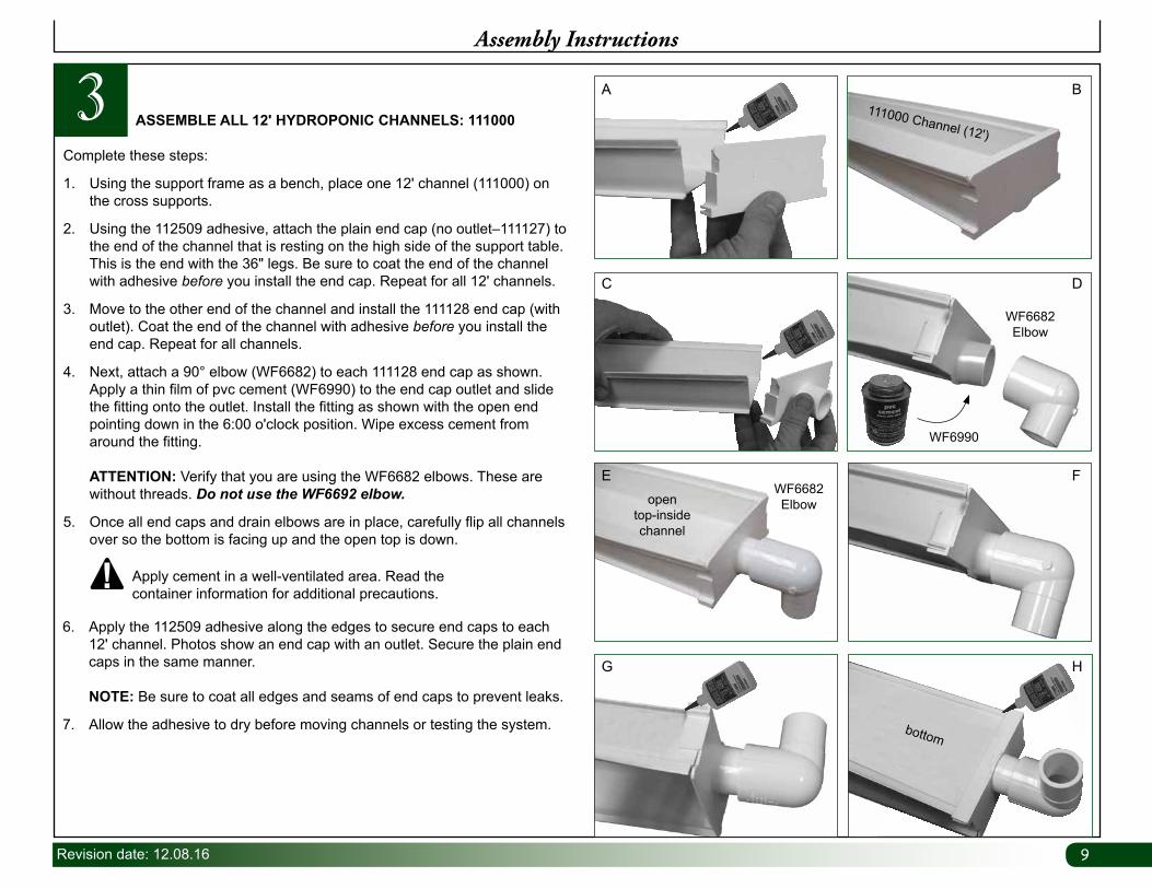
ASSEMBLE ALL 12' HYDROPONIC CHANNELS: 111000
Complete these steps:
1. Using the support frame as a bench, place one 12' channel (111000) on the cross supports.
2. Using the 112509 adhesive, attach the plain end cap (no outlet–111127) to the end of the channel that is resting on the high side of the support table. This is the end with the 36" legs. Be sure to coat the end of the channel with adhesive before you install the end cap. Repeat for all 12' channels.
3. Move to the other end of the channel and install the 111128 end cap (with outlet). Coat the end of the channel with adhesive before you install the end cap. Repeat for all channels.
4. Next, attach a 90° elbow (WF6682) to each 111128 end cap as shown. Apply a thin film of pvc cement (WF6990) to the end cap outlet and slide the fitting onto the outlet. Install the fitting as shown with the open end pointing down in the 6:00 o'clock position. Wipe excess cement from around the fitting. ATTENTION: Verify that you are using the WF6682 elbows. These are without threads. Do not use the WF6692 elbow.
5. Once all end caps and drain elbows are in place, carefully flip all channels over so the bottom is facing up and the open top is down.
6. Apply the 112509 adhesive along the edges to secure end caps to each 12' channel. Photos show an end cap with an outlet. Secure the plain end caps in the same manner. NOTE: Be sure to coat all edges and seams of end caps to prevent leaks.
7. Allow the adhesive to dry before moving channels or testing the system.
Apply cement in a well-ventilated area. Read the container information for additional precautions.
A B
C D
G
WF6682 Elbow
WF6990
111000 Channel (12')
WF6682 Elbowopen
top-inside channel
bottom
E F
H
1010 Revision date: 12.08.16
4Assembly Instructions
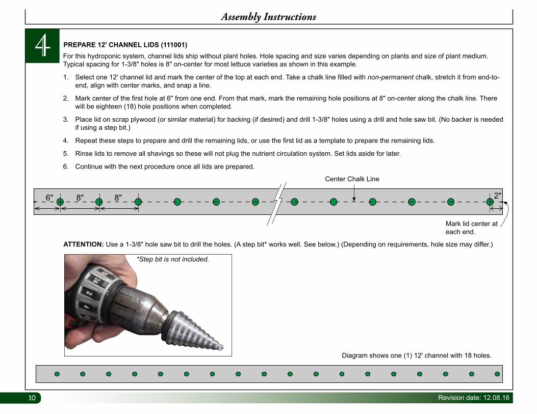
ATTENTION: Use a 1-3/8" hole saw bit to drill the holes. (A step bit* works well. See below.) (Depending on requirements, hole size may differ.)
6" 2"8" 8"
Mark lid center at each end.
Center Chalk Line
PREPARE 12' CHANNEL LIDS (111001) For this hydroponic system, channel lids ship without plant holes. Hole spacing and size varies depending on plants and size of plant medium. Typical spacing for 1-3/8" holes is 8" on-center for most lettuce varieties as shown in this example.
1. Select one 12' channel lid and mark the center of the top at each end. Take a chalk line filled with non-permanent chalk, stretch it from end-to-end, align with center marks, and snap a line.
2. Mark center of the first hole at 6" from one end. From that mark, mark the remaining hole positions at 8" on-center along the chalk line. There will be eighteen (18) hole positions when completed.
3. Place lid on scrap plywood (or similar material) for backing (if desired) and drill 1-3/8" holes using a drill and hole saw bit. (No backer is needed if using a step bit.)
4. Repeat these steps to prepare and drill the remaining lids, or use the first lid as a template to prepare the remaining lids.
5. Rinse lids to remove all shavings so these will not plug the nutrient circulation system. Set lids aside for later.
6. Continue with the next procedure once all lids are prepared.
*Step bit is not included.
Diagram shows one (1) 12' channel with 18 holes.
11Revision date: 12.08.16
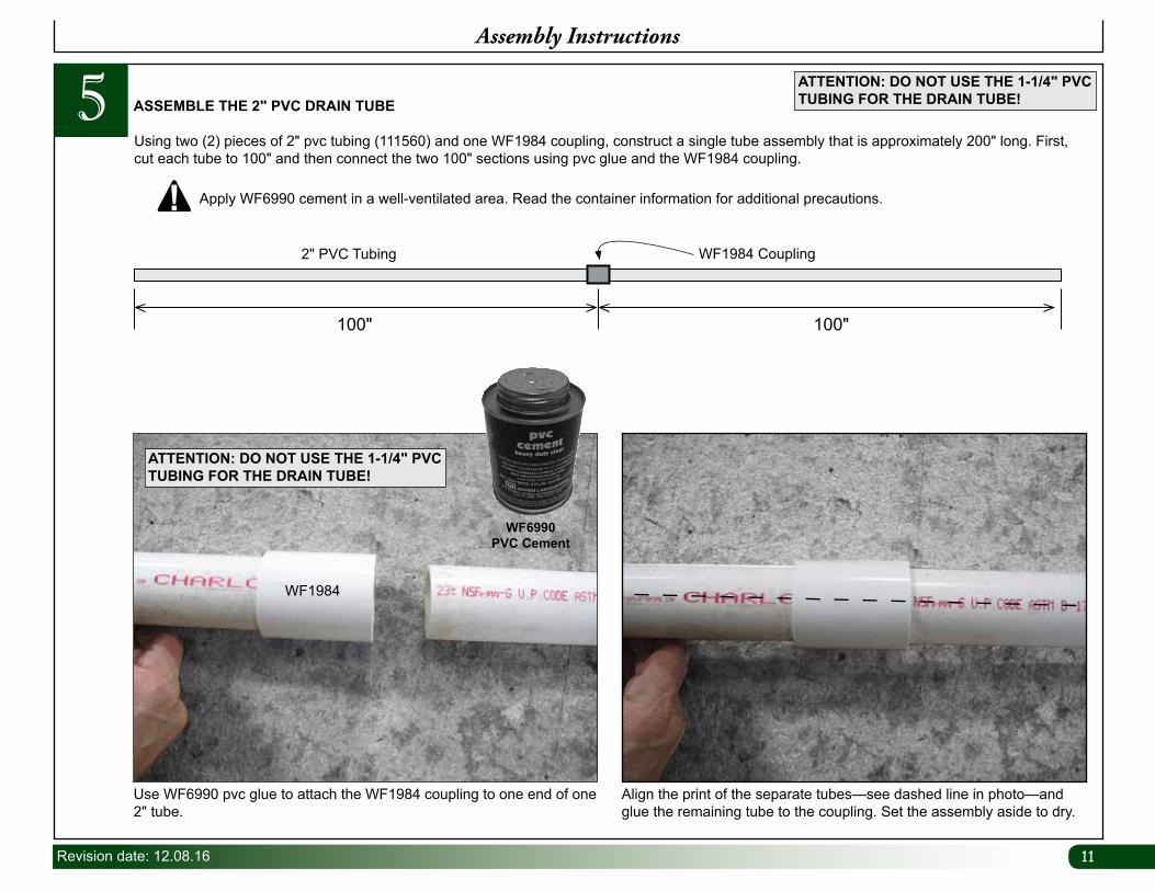
Using two (2) pieces of 2" pvc tubing (111560) and one WF1984 coupling, construct a single tube assembly that is approximately 200" long. First, cut each tube to 100" and then connect the two 100" sections using pvc glue and the WF1984 coupling.
ASSEMBLE THE 2" PVC DRAIN TUBE
Apply WF6990 cement in a well-ventilated area. Read the container information for additional precautions.
ATTENTION: DO NOT USE THE 1-1/4" PVC TUBING FOR THE DRAIN TUBE!
Use WF6990 pvc glue to attach the WF1984 coupling to one end of one 2" tube.
Align the print of the separate tubes—see dashed line in photo—and glue the remaining tube to the coupling. Set the assembly aside to dry.
WF1984
ATTENTION: DO NOT USE THE 1-1/4" PVC TUBING FOR THE DRAIN TUBE!
100" 100"
WF1984 Coupling2" PVC Tubing
WF6990PVC Cement
5Assembly Instructions
1212 Revision date: 12.08.16
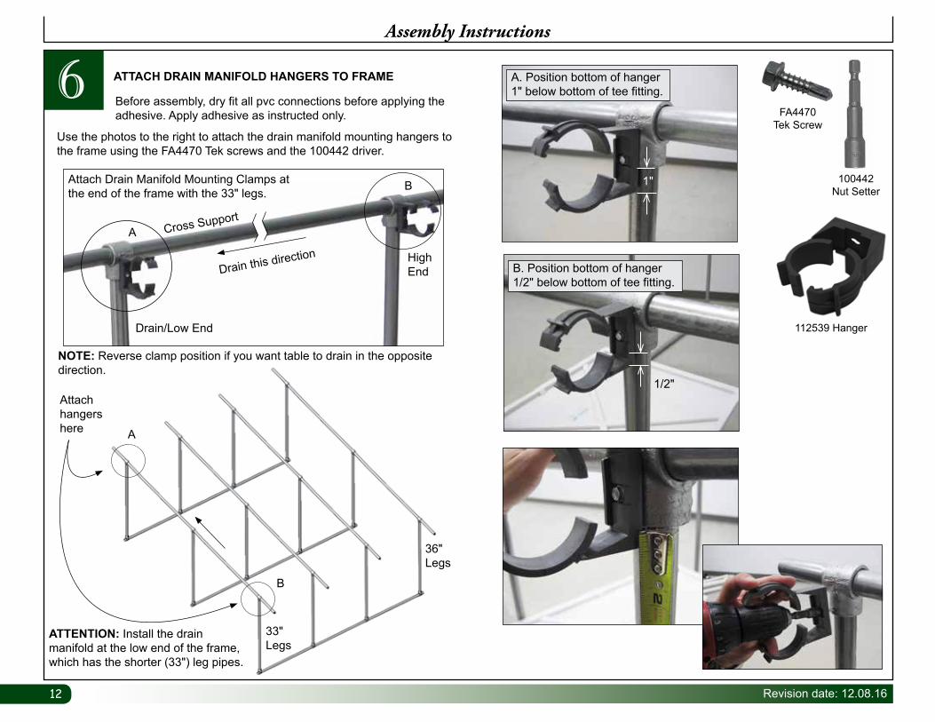
ATTENTION: Install the drain manifold at the low end of the frame, which has the shorter (33") leg pipes.
33" Legs
36" Legs
Attach hangers here A
B
6Assembly Instructions
Before assembly, dry fit all pvc connections before applying the adhesive. Apply adhesive as instructed only.
Use the photos to the right to attach the drain manifold mounting hangers to the frame using the FA4470 Tek screws and the 100442 driver.
ATTACH DRAIN MANIFOLD HANGERS TO FRAME
NOTE: Reverse clamp position if you want table to drain in the opposite direction.
112539 Hanger
100442 Nut Setter
FA4470 Tek Screw
1"
A. Position bottom of hanger 1" below bottom of tee fitting.
1/2"
B. Position bottom of hanger 1/2" below bottom of tee fitting.
High End
Drain/Low End
Drain this direction
Cross SupportA
BAttach Drain Manifold Mounting Clamps at the end of the frame with the 33" legs.
13Revision date: 12.08.16
Assembly Instructions
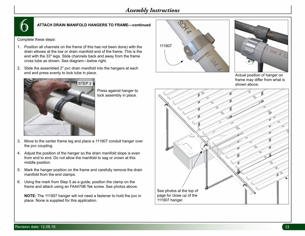
6 ATTACH DRAIN MANIFOLD HANGERS TO FRAME—continued
111907
See photos at the top of page for close up of the 111907 hanger.
Actual position of hanger on frame may differ from what is shown above.
Complete these steps:
1. Position all channels on the frame (if this has not been done) with the drain elbows at the low or drain manifold end of the frame. This is the end with the 33" legs. Slide channels back and away from the frame cross tube as shown. See diagram—below right.
2. Slide the assembled 2" pvc drain manifold into the hangers at each end and press evenly to lock tube in place.
3. Move to the center frame leg and place a 111907 conduit hanger over the pvc coupling.
4. Adjust the position of the hanger so the drain manifold slope is even from end to end. Do not allow the manifold to sag or crown at this middle position.
5. Mark the hanger position on the frame and carefully remove the drain manifold from the end clamps.
6. Using the mark from Step 5 as a guide, position the clamp on the frame and attach using an FA4470B Tek screw. See photos above. NOTE: The 111907 hanger will not need a fastener to hold the pvc in place. None is supplied for this application.
Press against hanger to lock assembly in place.
STEP 2
1414 Revision date: 12.08.16
7Assembly Instructions
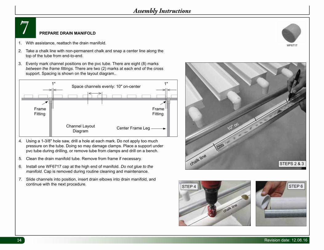
PREPARE DRAIN MANIFOLD
WF67171. With assistance, reattach the drain manifold.
2. Take a chalk line with non-permanent chalk and snap a center line along the top of the tube from end-to-end.
3. Evenly mark channel positions on the pvc tube. There are eight (8) marks between the frame fittings. There are two (2) marks at each end of the cross support. Spacing is shown on the layout diagram..
4. Using a 1-3/8" hole saw, drill a hole at each mark. Do not apply too much pressure on the tube. Doing so may damage clamps. Place a support under pvc tube during drilling, or remove tube from clamps and drill on a bench.
5. Clean the drain manifold tube. Remove from frame if necessary.
6. Install one WF6717 cap at the high end of manifold. Do not glue to the manifold. Cap is removed during routine cleaning and maintenance.
7. Slide channels into position, insert drain elbows into drain manifold, and continue with the next procedure.
1"1"
Channel Layout Diagram
Center Frame Leg
Frame Fitting
Frame Fitting
Space channels evenly: 10" on-center
STEP 4
chalk line
STEP 6
chalk line
STEPS 2 & 3
10" oc
15Revision date: 12.08.16
8Assembly Instructions
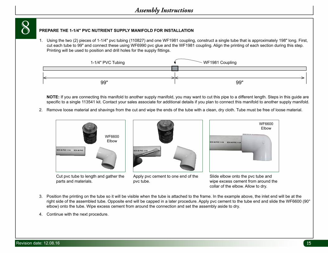
1. Using the two (2) pieces of 1-1/4" pvc tubing (110827) and one WF1981 coupling, construct a single tube that is approximately 198" long. First, cut each tube to 99" and connect these using WF6990 pvc glue and the WF1981 coupling. Align the printing of each section during this step. Printing will be used to position and drill holes for the supply fittings.
PREPARE THE 1-1/4" PVC NUTRIENT SUPPLY MANIFOLD FOR INSTALLATION
99" 99"
WF1981 Coupling1-1/4" PVC Tubing
NOTE: If you are connecting this manifold to another supply manifold, you may want to cut this pipe to a different length. Steps in this guide are specific to a single 113541 kit. Contact your sales associate for additional details if you plan to connect this manifold to another supply manifold.
2. Remove loose material and shavings from the cut and wipe the ends of the tube with a clean, dry cloth. Tube must be free of loose material.
Apply pvc cement to one end of the pvc tube.
Cut pvc tube to length and gather the parts and materials.
WF6600 Elbow
Slide elbow onto the pvc tube and wipe excess cement from around the collar of the elbow. Allow to dry.
WF6600 Elbow
SCH 40 PVC 1-1/4 SCH 40 PVC 1-1/4
SCH 40 PVC 1-1/4 PVSCH 40 PVC 1-1/4 SCH 40 PVC
3. Position the printing on the tube so it will be visible when the tube is attached to the frame. In the example above, the inlet end will be at the right side of the assembled tube. Opposite end will be capped in a later procedure. Apply pvc cement to the tube end and slide the WF6600 (90° elbow) onto the tube. Wipe excess cement from around the connection and set the assembly aside to dry.
4. Continue with the next procedure.
1616 Revision date: 12.08.16
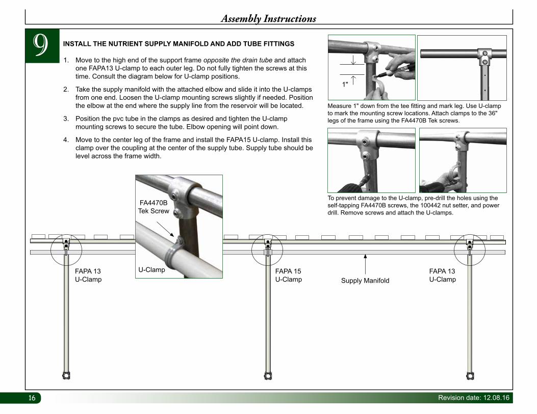
9Assembly Instructions
1. Move to the high end of the support frame opposite the drain tube and attach one FAPA13 U-clamp to each outer leg. Do not fully tighten the screws at this time. Consult the diagram below for U-clamp positions.
2. Take the supply manifold with the attached elbow and slide it into the U-clamps from one end. Loosen the U-clamp mounting screws slightly if needed. Position the elbow at the end where the supply line from the reservoir will be located.
3. Position the pvc tube in the clamps as desired and tighten the U-clamp mounting screws to secure the tube. Elbow opening will point down.
4. Move to the center leg of the frame and install the FAPA15 U-clamp. Install this clamp over the coupling at the center of the supply tube. Supply tube should be level across the frame width.
INSTALL THE NUTRIENT SUPPLY MANIFOLD AND ADD TUBE FITTINGS
To prevent damage to the U-clamp, pre-drill the holes using the self-tapping FA4470B screws, the 100442 nut setter, and power drill. Remove screws and attach the U-clamps.
Measure 1" down from the tee fitting and mark leg. Use U-clamp to mark the mounting screw locations. Attach clamps to the 36" legs of the frame using the FA4470B Tek screws.
1"
Supply ManifoldFAPA 13U-Clamp
FAPA 15U-Clamp
FAPA 13U-Clamp
U-Clamp
FA4470B Tek Screw
17Revision date: 12.08.16
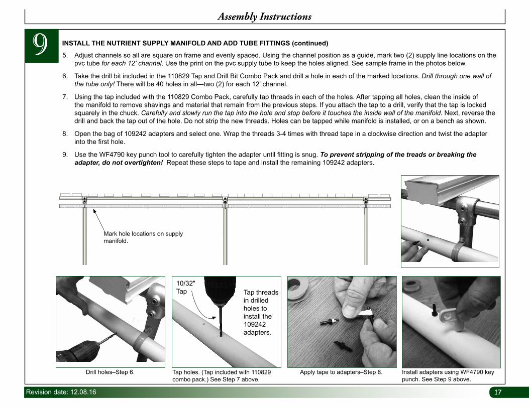
9 5. Adjust channels so all are square on frame and evenly spaced. Using the channel position as a guide, mark two (2) supply line locations on the pvc tube for each 12' channel. Use the print on the pvc supply tube to keep the holes aligned. See sample frame in the photos below.
6. Take the drill bit included in the 110829 Tap and Drill Bit Combo Pack and drill a hole in each of the marked locations. Drill through one wall of the tube only! There will be 40 holes in all—two (2) for each 12' channel.
7. Using the tap included with the 110829 Combo Pack, carefully tap threads in each of the holes. After tapping all holes, clean the inside of the manifold to remove shavings and material that remain from the previous steps. If you attach the tap to a drill, verify that the tap is locked squarely in the chuck. Carefully and slowly run the tap into the hole and stop before it touches the inside wall of the manifold. Next, reverse the drill and back the tap out of the hole. Do not strip the new threads. Holes can be tapped while manifold is installed, or on a bench as shown.
8. Open the bag of 109242 adapters and select one. Wrap the threads 3-4 times with thread tape in a clockwise direction and twist the adapter into the first hole.
9. Use the WF4790 key punch tool to carefully tighten the adapter until fitting is snug. To prevent stripping of the treads or breaking the adapter, do not overtighten! Repeat these steps to tape and install the remaining 109242 adapters.
INSTALL THE NUTRIENT SUPPLY MANIFOLD AND ADD TUBE FITTINGS (continued)
Assembly Instructions
Drill holes–Step 6. Apply tape to adapters–Step 8. Install adapters using WF4790 key punch. See Step 9 above.
Tap holes. (Tap included with 110829 combo pack.) See Step 7 above.
Tap threads in drilled holes to install the 109242 adapters.
10/32" Tap
Mark hole locations on supply manifold.
1818 Revision date: 12.08.16
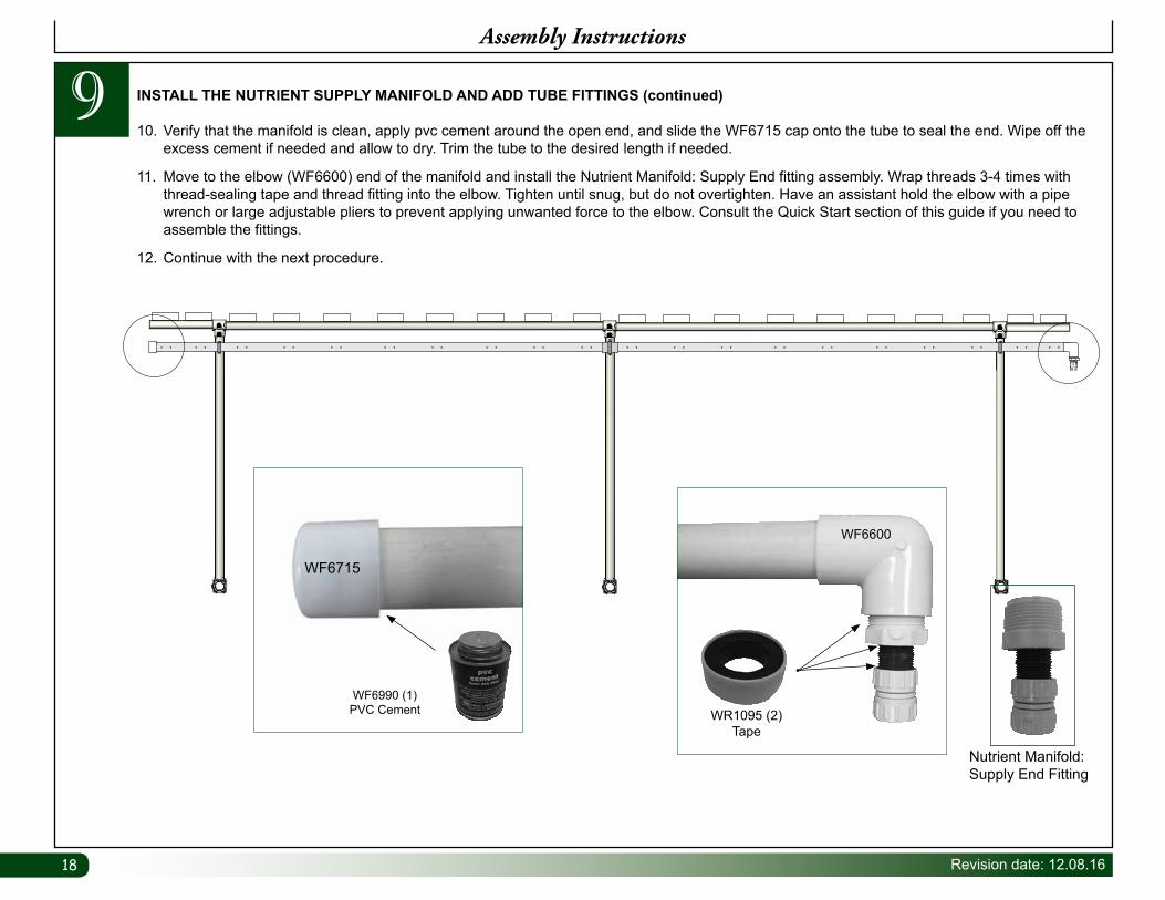
10. Verify that the manifold is clean, apply pvc cement around the open end, and slide the WF6715 cap onto the tube to seal the end. Wipe off the excess cement if needed and allow to dry. Trim the tube to the desired length if needed.
11. Move to the elbow (WF6600) end of the manifold and install the Nutrient Manifold: Supply End fitting assembly. Wrap threads 3-4 times with thread-sealing tape and thread fitting into the elbow. Tighten until snug, but do not overtighten. Have an assistant hold the elbow with a pipe wrench or large adjustable pliers to prevent applying unwanted force to the elbow. Consult the Quick Start section of this guide if you need to assemble the fittings.
12. Continue with the next procedure.
INSTALL THE NUTRIENT SUPPLY MANIFOLD AND ADD TUBE FITTINGS (continued)
Assembly Instructions
WF6990 (1)PVC Cement
WF6715
Nutrient Manifold:Supply End Fitting
WR1095 (2)Tape
WF6600
9
19Revision date: 12.08.16
Assembly Instructions
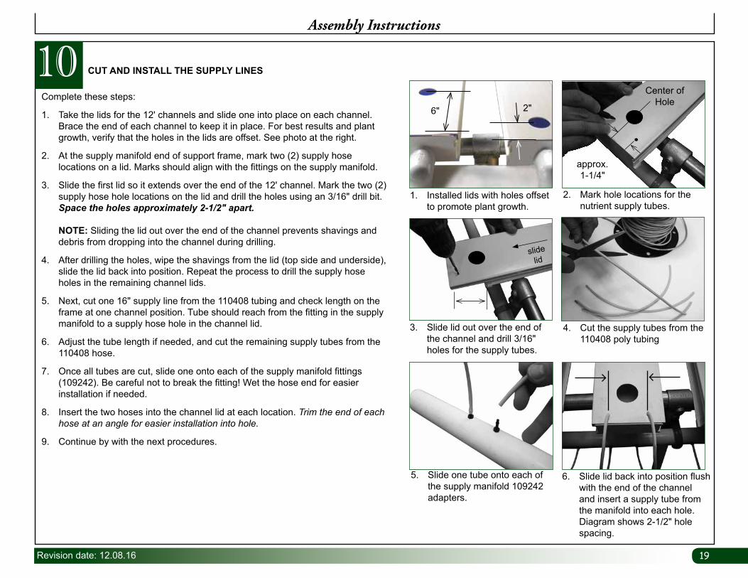
Complete these steps:
1. Take the lids for the 12' channels and slide one into place on each channel. Brace the end of each channel to keep it in place. For best results and plant growth, verify that the holes in the lids are offset. See photo at the right.
2. At the supply manifold end of support frame, mark two (2) supply hose locations on a lid. Marks should align with the fittings on the supply manifold.
3. Slide the first lid so it extends over the end of the 12' channel. Mark the two (2) supply hose hole locations on the lid and drill the holes using an 3/16" drill bit. Space the holes approximately 2-1/2" apart. NOTE: Sliding the lid out over the end of the channel prevents shavings and debris from dropping into the channel during drilling.
4. After drilling the holes, wipe the shavings from the lid (top side and underside), slide the lid back into position. Repeat the process to drill the supply hose holes in the remaining channel lids.
5. Next, cut one 16" supply line from the 110408 tubing and check length on the frame at one channel position. Tube should reach from the fitting in the supply manifold to a supply hose hole in the channel lid.
6. Adjust the tube length if needed, and cut the remaining supply tubes from the 110408 hose.
7. Once all tubes are cut, slide one onto each of the supply manifold fittings (109242). Be careful not to break the fitting! Wet the hose end for easier installation if needed.
8. Insert the two hoses into the channel lid at each location. Trim the end of each hose at an angle for easier installation into hole.
9. Continue by with the next procedures.
CUT AND INSTALL THE SUPPLY LINES
1. Installed lids with holes offset to promote plant growth.
3. Slide lid out over the end of the channel and drill 3/16" holes for the supply tubes.
5. Slide one tube onto each of the supply manifold 109242 adapters.
2. Mark hole locations for the nutrient supply tubes.
4. Cut the supply tubes from the 110408 poly tubing
6. Slide lid back into position flush with the end of the channel and insert a supply tube from the manifold into each hole. Diagram shows 2-1/2" hole spacing.
slide lid
approx. 1-1/4"
Center of Hole
106" 2"
2020 Revision date: 12.08.16
11Assembly Instructions
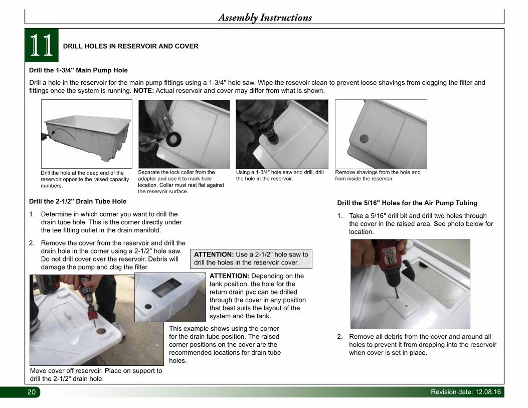
DRILL HOLES IN RESERVOIR AND COVER
Drill the 5/16" Holes for the Air Pump Tubing
1. Take a 5/16" drill bit and drill two holes through the cover in the raised area. See photo below for location.
2. Remove all debris from the cover and around all holes to prevent it from dropping into the reservoir when cover is set in place.
Drill a hole in the reservoir for the main pump fittings using a 1-3/4" hole saw. Wipe the resevoir clean to prevent loose shavings from clogging the filter and fittings once the system is running. NOTE: Actual reservoir and cover may differ from what is shown.
Drill the hole at the deep end of the reservoir opposite the raised capacity numbers.
Separate the lock collar from the adaptor and use it to mark hole location. Collar must rest flat against the reservoir surface.
Using a 1-3/4" hole saw and drill, drill the hole in the reservoir.
Remove shavings from the hole and from inside the reservoir.
Drill the 1-3/4" Main Pump Hole
ATTENTION: Use a 2-1/2" hole saw to drill the holes in the reservoir cover.
ATTENTION: Depending on the tank position, the hole for the return drain pvc can be drilled through the cover in any position that best suits the layout of the system and the tank.
Move cover off reservoir. Place on support to drill the 2-1/2" drain hole.
Drill the 2-1/2" Drain Tube Hole
1. Determine in which corner you want to drill the drain tube hole. This is the corner directly under the tee fitting outlet in the drain manifold.
2. Remove the cover from the reservoir and drill the drain hole in the corner using a 2-1/2" hole saw. Do not drill cover over the reservoir. Debris will damage the pump and clog the filter.
This example shows using the corner for the drain tube position. The raised corner positions on the cover are the recommended locations for drain tube holes.
21Revision date: 12.08.16
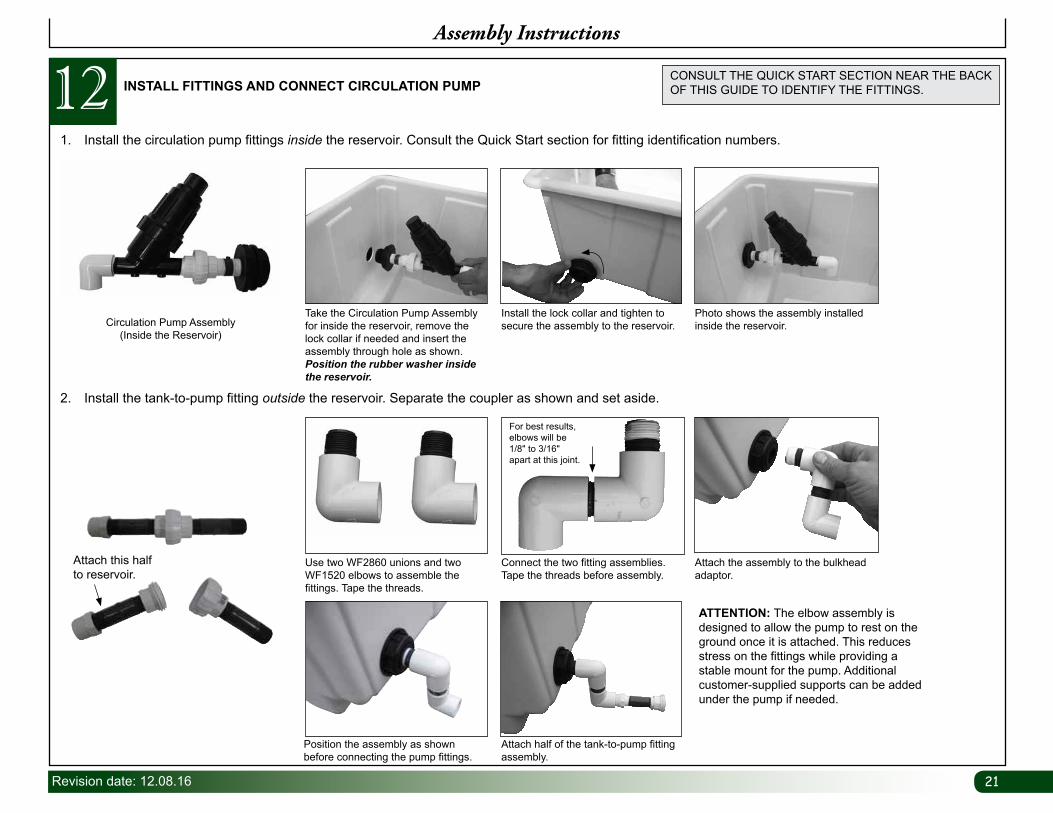
INSTALL FITTINGS AND CONNECT CIRCULATION PUMP121. Install the circulation pump fittings inside the reservoir. Consult the Quick Start section for fitting identification numbers.
Assembly Instructions
CONSULT THE QUICK START SECTION NEAR THE BACK OF THIS GUIDE TO IDENTIFY THE FITTINGS.
Attach this half to reservoir.
2. Install the tank-to-pump fitting outside the reservoir. Separate the coupler as shown and set aside.
Position the assembly as shown before connecting the pump fittings.
Circulation Pump Assembly(Inside the Reservoir)
Attach half of the tank-to-pump fitting assembly.
Take the Circulation Pump Assembly for inside the reservoir, remove the lock collar if needed and insert the assembly through hole as shown. Position the rubber washer inside the reservoir.
Photo shows the assembly installed inside the reservoir.
Install the lock collar and tighten to secure the assembly to the reservoir.
ATTENTION: The elbow assembly is designed to allow the pump to rest on the ground once it is attached. This reduces stress on the fittings while providing a stable mount for the pump. Additional customer-supplied supports can be added under the pump if needed.
Use two WF2860 unions and two WF1520 elbows to assemble the fittings. Tape the threads.
Attach the assembly to the bulkhead adaptor.
Connect the two fitting assemblies. Tape the threads before assembly.
For best results, elbows will be 1/8" to 3/16" apart at this joint.
2222 Revision date: 12.08.16
Assembly Instructions
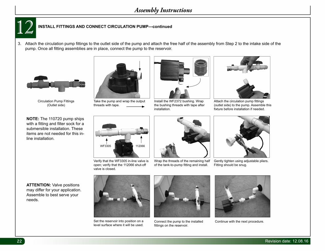
INSTALL FITTINGS AND CONNECT CIRCULATION PUMP—continued12
NOTE: The 110720 pump ships with a fitting and filter sock for a submersible installation. These items are not needed for this in-line installation.
ATTENTION: Valve positions may differ for your application. Assemble to best serve your needs.
3. Attach the circulation pump fittings to the outlet side of the pump and attach the free half of the assembly from Step 2 to the intake side of the pump. Once all fitting assemblies are in place, connect the pump to the reservoir.
Verify that the WF3305 in-line valve is open; verify that the 112066 shut-off valve is closed.
Gently tighten using adjustable pliers. Fitting should be snug.
Wrap the threads of the remaining half of the tank-to-pump fitting and install.
Set the reservoir into position on a level surface where it will be used.
Connect the pump to the installed fittings on the reservoir.
Continue with the next procedure.
Circulation Pump Fittings(Outlet side)
WF3305 112066
Take the pump and wrap the output threads with tape.
Attach the circulation pump fittings (outlet side) to the pump. Assemble this fixture before installation if needed.
Install the WF2372 bushing. Wrap the bushing threads with tape after installation.
23Revision date: 12.08.16
13Assembly Instructions
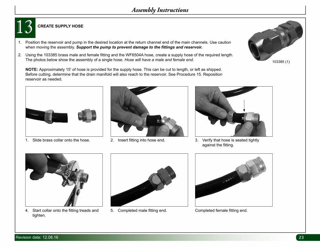
CREATE SUPPLY HOSE
1. Position the reservoir and pump in the desired location at the return channel end of the main channels. Use caution when moving the assembly. Support the pump to prevent damage to the fittings and reservoir.
2. Using the 103385 brass male and female fitting and the WF6504A hose, create a supply hose of the required length. The photos below show the assembly of a single hose. Hose will have a male and female end. NOTE: Approximately 15' of hose is provided for the supply hose. This can be cut to length, or left as shipped. Before cutting, determine that the drain manifold will also reach to the reservoir. See Procedure 15. Reposition reservoir as needed.
4. Start collar onto the fitting treads and tighten.
5. Completed male fitting end. Completed female fitting end.
1. Slide brass collar onto the hose. 2. Insert fitting into hose end. 3. Verify that hose is seated tightly against the fitting.
103385 (1)
2424 Revision date: 12.08.16
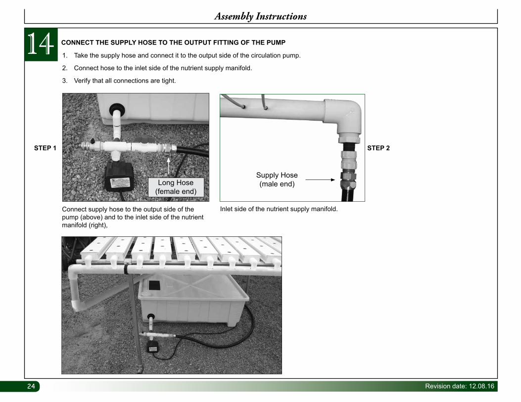
14Assembly Instructions
CONNECT THE SUPPLY HOSE TO THE OUTPUT FITTING OF THE PUMP
1. Take the supply hose and connect it to the output side of the circulation pump.
2. Connect hose to the inlet side of the nutrient supply manifold.
3. Verify that all connections are tight.
STEP 1 STEP 2
Connect supply hose to the output side of the pump (above) and to the inlet side of the nutrient manifold (right),
Inlet side of the nutrient supply manifold.
Supply Hose (male end)Long Hose
(female end)
25Revision date: 12.08.16
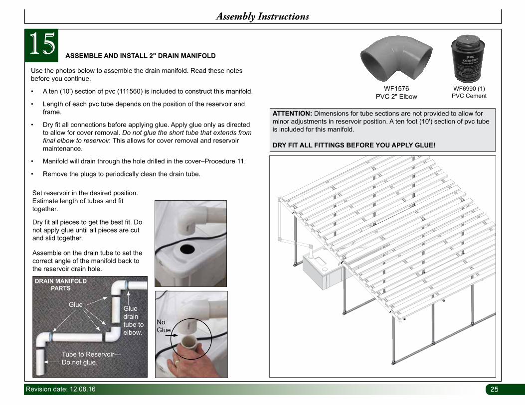
15Assembly Instructions
Use the photos below to assemble the drain manifold. Read these notes before you continue.
• A ten (10') section of pvc (111560) is included to construct this manifold.
• Length of each pvc tube depends on the position of the reservoir and frame.
• Dry fit all connections before applying glue. Apply glue only as directed to allow for cover removal. Do not glue the short tube that extends from final elbow to reservoir. This allows for cover removal and reservoir maintenance.
• Manifold will drain through the hole drilled in the cover–Procedure 11.
• Remove the plugs to periodically clean the drain tube.
ASSEMBLE AND INSTALL 2" DRAIN MANIFOLD
WF6990 (1)PVC Cement
ATTENTION: Dimensions for tube sections are not provided to allow for minor adjustments in reservoir position. A ten foot (10') section of pvc tube is included for this manifold.
DRY FIT ALL FITTINGS BEFORE YOU APPLY GLUE!
Set reservoir in the desired position. Estimate length of tubes and fit together.
No Glue
Dry fit all pieces to get the best fit. Do not apply glue until all pieces are cut and slid together.
Assemble on the drain tube to set the correct angle of the manifold back to the reservoir drain hole.
Glue Glue drain tube to elbow.
Tube to Reservoir—Do not glue.
DRAIN MANIFOLD PARTS
WF1576 PVC 2" Elbow
2626 Revision date: 12.08.16
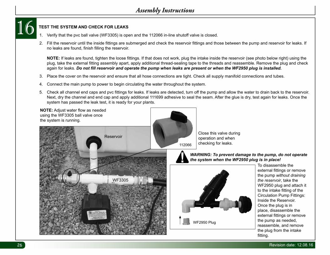
TEST THE SYSTEM AND CHECK FOR LEAKS16 1. Verify that the pvc ball valve (WF3305) is open and the 112066 in-line shutoff valve is closed.
2. Fill the reservoir until the inside fittings are submerged and check the reservoir fittings and those between the pump and reservoir for leaks. If no leaks are found, finish filling the reservoir. NOTE: If leaks are found, tighten the loose fittings. If that does not work, plug the intake inside the reservoir (see photo below right) using the plug, take the external fitting assembly apart, apply additional thread-sealing tape to the threads and reassemble. Remove the plug and check again for leaks. Do not fill reservoir and operate the pump when leaks are present or when the WF2950 plug is installed.
3. Place the cover on the reservoir and ensure that all hose connections are tight. Check all supply manifold connections and tubes.
4. Connect the main pump to power to begin circulating the water throughout the system.
5. Check all channel end caps and pvc fittings for leaks. If leaks are detected, turn off the pump and allow the water to drain back to the reservoir. Next, dry the channel and end cap and apply additional 111699 adhesive to seal the seam. After the glue is dry, test again for leaks. Once the system has passed the leak test, it is ready for your plants.
Assembly Instructions
WF3305
Reservoir
NOTE: Adjust water flow as needed using the WF3305 ball valve once the system is running.
To disassemble the external fittings or remove the pump without draining the reservoir, take the WF2950 plug and attach it to the intake fitting of the Circulation Pump Fittings: Inside the Reservoir. Once the plug is in place, disassemble the external fittings or remove the pump as needed, reassemble, and remove the plug from the intake fitting.
WF2950 Plug
WARNING: To prevent damage to the pump, do not operate the system when the WF2950 plug is in place!
Close this valve during operation and when checking for leaks. 112066
27Revision date: 12.08.16
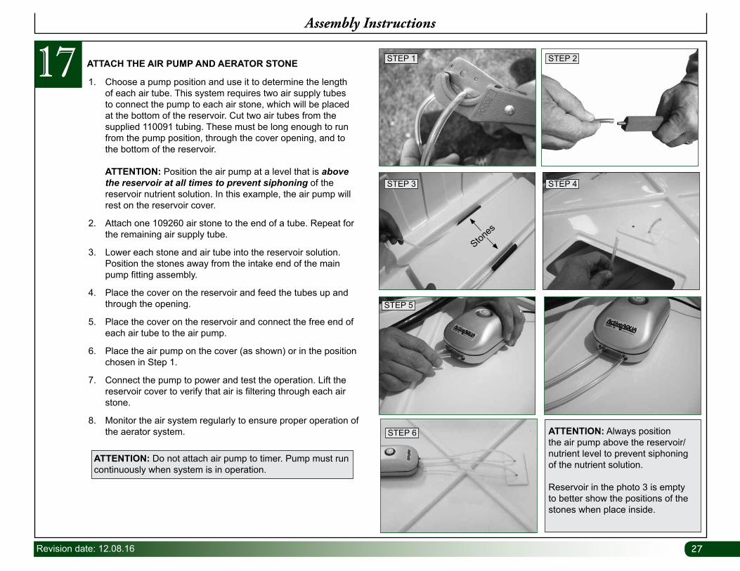
17Assembly Instructions
1. Choose a pump position and use it to determine the length of each air tube. This system requires two air supply tubes to connect the pump to each air stone, which will be placed at the bottom of the reservoir. Cut two air tubes from the supplied 110091 tubing. These must be long enough to run from the pump position, through the cover opening, and to the bottom of the reservoir. ATTENTION: Position the air pump at a level that is above the reservoir at all times to prevent siphoning of the reservoir nutrient solution. In this example, the air pump will rest on the reservoir cover.
2. Attach one 109260 air stone to the end of a tube. Repeat for the remaining air supply tube.
3. Lower each stone and air tube into the reservoir solution. Position the stones away from the intake end of the main pump fitting assembly.
4. Place the cover on the reservoir and feed the tubes up and through the opening.
5. Place the cover on the reservoir and connect the free end of each air tube to the air pump.
6. Place the air pump on the cover (as shown) or in the position chosen in Step 1.
7. Connect the pump to power and test the operation. Lift the reservoir cover to verify that air is filtering through each air stone.
8. Monitor the air system regularly to ensure proper operation of the aerator system. ATTENTION: Always position
the air pump above the reservoir/nutrient level to prevent siphoning of the nutrient solution.
Reservoir in the photo 3 is empty to better show the positions of the stones when place inside.
ATTACH THE AIR PUMP AND AERATOR STONE STEP 1
STEP 3
STEP 6
STEP 2
STEP 4
STEP 5
Stones
ATTENTION: Do not attach air pump to timer. Pump must run continuously when system is in operation.
2828 Revision date: 12.08.16
18Assembly Instructions
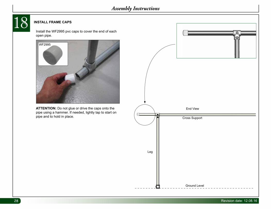
INSTALL FRAME CAPS
Install the WF2995 pvc caps to cover the end of each open pipe.
ATTENTION: Do not glue or drive the caps onto the pipe using a hammer. If needed, lightly tap to start on pipe and to hold in place.
WF2995
Ground Level
End View
Leg
Cross Support
29Revision date: 12.08.16
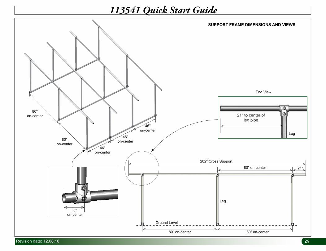
113541 Quick Start GuideSUPPORT FRAME DIMENSIONS AND VIEWS
46"on-center
80"on-center
80"on-center
3"on-center
46"on-center
46"on-center
80" on-center
80" on-center 21"
Ground Level
Leg
202" Cross Support
80" on-center
End View
21" to center of leg pipe
Leg
30 Revision date: 12.08.16
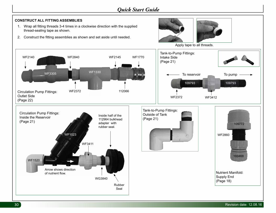
Quick Start Guide
1. Wrap all fitting threads 3-4 times in a clockwise direction with the supplied thread-sealing tape as shown.
2. Construct the fitting assemblies as shown and set aside until needed.
CONSTRUCT ALL FITTING ASSEMBLIES
Tank-to-Pump Fittings:Outside of Tank(Page 21)
WF2860
109772
103468
Nutrient Manifold: Supply End(Page 18)
WF2372 WF3412
109793 109793
Tank-to-Pump Fittings: Intake Side(Page 21)
To reservoir To pump
Apply tape to all threads.
WF1330
WF2372 112066
WF2840 WF2145 WF1770WF2140
WF3305
Circulation Pump Fittings: Outlet Side(Page 22)
WF1520
WF1023
Rubber Seal
Inside half of the 112964 bulkhead adapter with rubber seal.
Arrow shows direction of nutrient flow.
WG3840
Circulation Pump Fittings: Inside the Reservoir(Page 21)
WF3411
31Revision date: 12.08.16
Additional Information
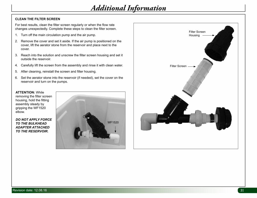
For best results, clean the filter screen regularly or when the flow rate changes unexpectedly. Complete these steps to clean the filter screen.
1. Turn off the main circulation pump and the air pump.
2. Remove the cover and set it aside. If the air pump is positioned on the cover, lift the aerator stone from the reservoir and place next to the cover.
3. Reach into the solution and unscrew the filter screen housing and set it outside the reservoir.
4. Carefully lift the screen from the assembly and rinse it with clean water.
5. After cleaning, reinstall the screen and filter housing.
6. Set the aerator stone into the reservoir (if needed), set the cover on the reservoir and turn on the pumps.
CLEAN THE FILTER SCREEN
ATTENTION: While removing the filter screen housing, hold the fitting assembly steady by gripping the WF1520 elbow.
DO NOT APPLY FORCE TO THE BULKHEAD ADAPTER ATTACHED TO THE RESERVOIR.
Filter Screen Housing
Filter Screen
WF1520
32 Revision date: 12.08.16
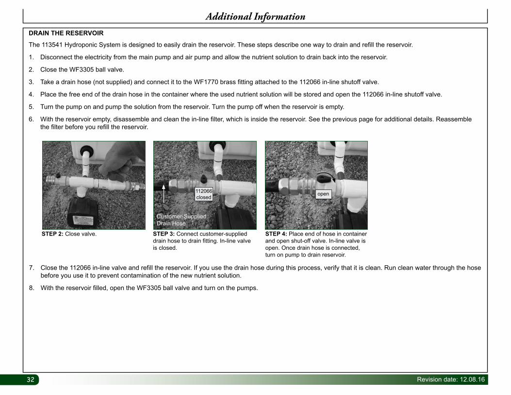
The 113541 Hydroponic System is designed to easily drain the reservoir. These steps describe one way to drain and refill the reservoir.
1. Disconnect the electricity from the main pump and air pump and allow the nutrient solution to drain back into the reservoir.
2. Close the WF3305 ball valve.
3. Take a drain hose (not supplied) and connect it to the WF1770 brass fitting attached to the 112066 in-line shutoff valve.
4. Place the free end of the drain hose in the container where the used nutrient solution will be stored and open the 112066 in-line shutoff valve.
5. Turn the pump on and pump the solution from the reservoir. Turn the pump off when the reservoir is empty.
6. With the reservoir empty, disassemble and clean the in-line filter, which is inside the reservoir. See the previous page for additional details. Reassemble the filter before you refill the reservoir.
DRAIN THE RESERVOIR
Additional Information
7. Close the 112066 in-line valve and refill the reservoir. If you use the drain hose during this process, verify that it is clean. Run clean water through the hose before you use it to prevent contamination of the new nutrient solution.
8. With the reservoir filled, open the WF3305 ball valve and turn on the pumps.
STEP 2: Close valve. STEP 3: Connect customer-supplied drain hose to drain fitting. In-line valve is closed.
STEP 4: Place end of hose in container and open shut-off valve. In-line valve is open. Once drain hose is connected, turn on pump to drain reservoir.
Customer-SuppliedDrain Hose
112066 closed
open
33Revision date: 12.08.16
Additional Information
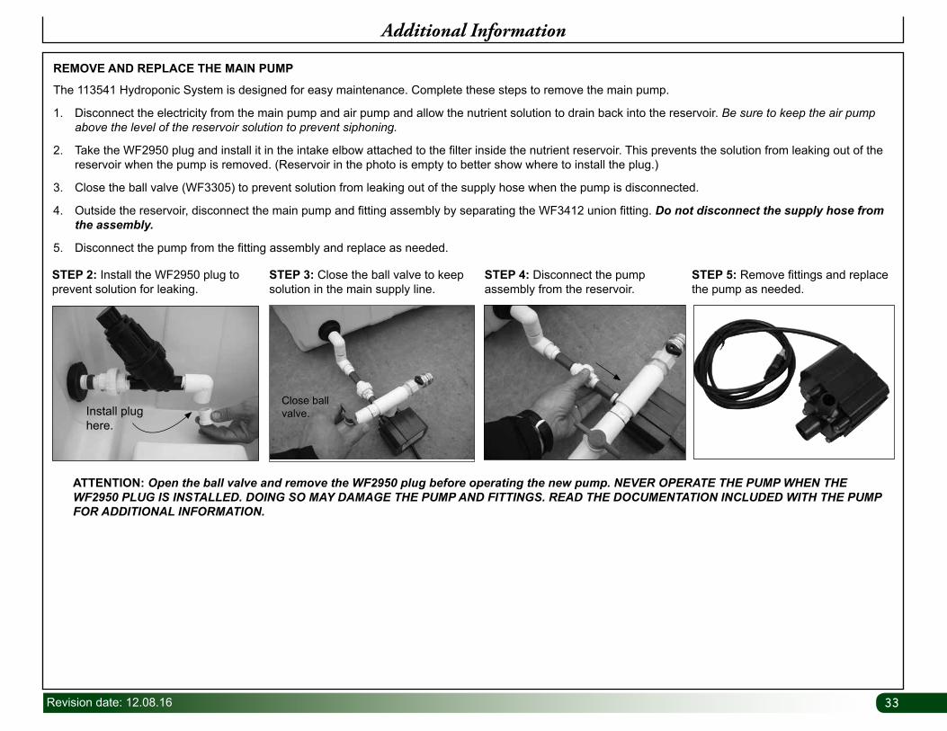
The 113541 Hydroponic System is designed for easy maintenance. Complete these steps to remove the main pump.
1. Disconnect the electricity from the main pump and air pump and allow the nutrient solution to drain back into the reservoir. Be sure to keep the air pump above the level of the reservoir solution to prevent siphoning.
2. Take the WF2950 plug and install it in the intake elbow attached to the filter inside the nutrient reservoir. This prevents the solution from leaking out of the reservoir when the pump is removed. (Reservoir in the photo is empty to better show where to install the plug.)
3. Close the ball valve (WF3305) to prevent solution from leaking out of the supply hose when the pump is disconnected.
4. Outside the reservoir, disconnect the main pump and fitting assembly by separating the WF3412 union fitting. Do not disconnect the supply hose from the assembly.
5. Disconnect the pump from the fitting assembly and replace as needed.
REMOVE AND REPLACE THE MAIN PUMP
ATTENTION: Open the ball valve and remove the WF2950 plug before operating the new pump. NEVER OPERATE THE PUMP WHEN THE WF2950 PLUG IS INSTALLED. DOING SO MAY DAMAGE THE PUMP AND FITTINGS. READ THE DOCUMENTATION INCLUDED WITH THE PUMP FOR ADDITIONAL INFORMATION.
STEP 2: Install the WF2950 plug to prevent solution for leaking.
STEP 3: Close the ball valve to keep solution in the main supply line.
STEP 4: Disconnect the pump assembly from the reservoir.
STEP 5: Remove fittings and replace the pump as needed.
Install plug here.
Close ball valve.
34 Revision date: 12.08.16
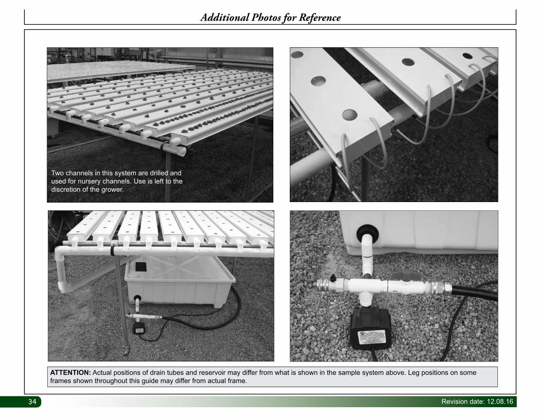
Additional Photos for Reference
ATTENTION: Actual positions of drain tubes and reservoir may differ from what is shown in the sample system above. Leg positions on some frames shown throughout this guide may differ from actual frame.
Two channels in this system are drilled and used for nursery channels. Use is left to the discretion of the grower.

35Revision date: 12.08.16
PAGE RESERVED FOR CUSTOMER NOTES AND RECORDS