Embed Size (px)
Citation preview

HYDRODYNAMICS OF THE ELECTRICAL DISCHARGE MACHINING PROCESS (EDM) Patrick Haas, Prof. HES hepia-cmefe

2 http://www.cmefe.ch
HEPIA-CMEFE GROUP

3 http://www.cmefe.ch
Dominique Aegerter (Moto2)
Avintia (MotoGP)
Drone de mesure de la pollution
HEPIA-CMEFE GROUP

4 http://www.cmefe.ch
AUDIT OF F1 TEAMS ! 2010-13 hepia-cmefe is an official partner of the Formula
One Teams Association (FOTA) ! Roberto Putzu and Patrick Haas act as auditors regarding
the implementation of the « Aerodynamic testing and CFD simulation Regulation » Formula One Teams
Association
Force India
HEPIA-CMEFE GROUP

5 http://www.cmefe.ch
F1 WIND TUNNEL CHARACTERISTICS
! Regulation adopted for cost restrictions ! ! 60% scale models max. ! 50 m/s maximal air speed ! Rolling road (belt) ! Boundary layer succion ! Test for several angles of pitch, yaw and roll ! More than 500 complete runs (offsets and all angles) per
month, in addition to CFD work
Aerodynamic Testing Restrictions (FOTA)
HEPIA-CMEFE GROUP

6 http://www.cmefe.ch
CFD CAPABILITIES OF F1 TEAMS
! The calculation power of CFD jobs regarding the car external aerodynamics is limited
! Up to 1’500 CFD jobs per month (50 per day mean!)
! Up to 18 h for a full car job on the cluster
Aerodynamic CFD Restrictions (FOTA)
Sauber F1
HEPIA-CMEFE GROUP
7 http://www.cmefe.ch
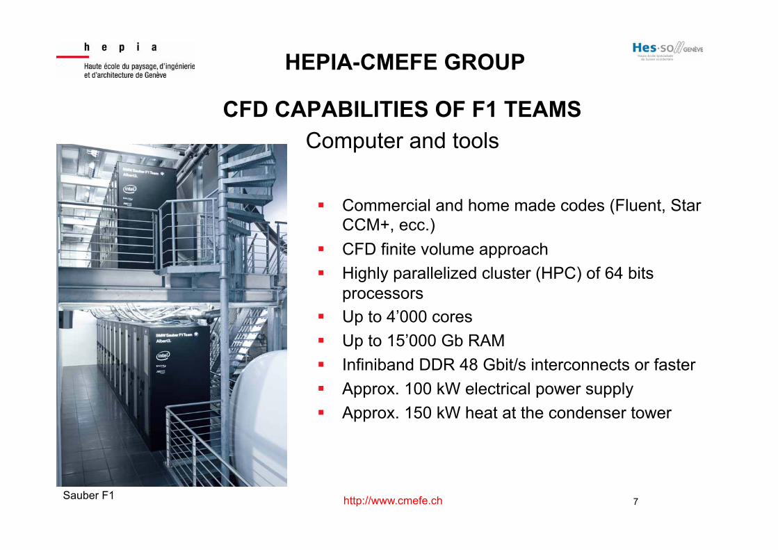
CFD CAPABILITIES OF F1 TEAMS Computer and tools
! Commercial and home made codes (Fluent, Star CCM+, ecc.)
! CFD finite volume approach ! Highly parallelized cluster (HPC) of 64 bits
processors ! Up to 4’000 cores ! Up to 15’000 Gb RAM ! Infiniband DDR 48 Gbit/s interconnects or faster ! Approx. 100 kW electrical power supply ! Approx. 150 kW heat at the condenser tower
Sauber F1
HEPIA-CMEFE GROUP

8 http://www.cmefe.ch
HYDRODYNAMICS OF THE ELECTRICAL DISCHARGE MACHINING PROCESS (EDM)
« Use of electrical discharges to remove material »
The processes available today are the following :
! EDM die-sinking (ex. credit card injection moulds)
! Wire-EDM (ex. extrusion moulds)
! EDM hole drilling (ex. engine injectors diam. < 0.100 mm)
! EDM milling (ex. complex parts, small, hard material). New method developed by Agie Charmiles with hepia (Prof. J. Richard)

9 http://www.cmefe.ch
SOME BACKGROUND : THE EDM PROCESS
1. Application of a potential between the electrode and the material
2. A ionized channel is created
3. A plasma is formed. The spark generator decrease the potential to stabilize the current.
4. After an imposed time, the current is stopped. A plasma implosion is created (low pressure in the plasma zone). Dielectric cooling effect.
5. Liquefied material is removed from the surface.
3 4 5
When the plasma disappears, liquefied material is ejected in the dielectric. Solid particles are formed.

10 http://www.cmefe.ch
THE EDM PROCESS
Views of craters
11 http://www.cmefe.ch
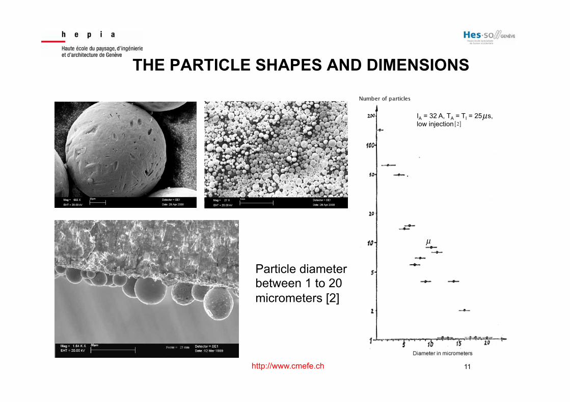
THE PARTICLE SHAPES AND DIMENSIONS
IA = 32 A, TA = TI = 25 s, low injection 2[ ]
µ
µ
Particle diameter between 1 to 20 micrometers [2]

12 http://www.cmefe.ch
WHY HYDRODYNAMICS IS A KEY FACTOR ?
! The spark starts at the location where the dielectric resistance is the smallest (gap, fluid conductivity, ecc.)
! The EDM process can work only if the next spark moves
to the smallest gap location (another location !) ! There is a necessity to find a way to regenerate the
dielectric and to clean the gap, removing the particles. Although, the spark stays all the time at the same location and the process can not work.
The production speed is partially governed by hydrodynamics. Project motivation (CFD, test rig, on site production tests)

13 http://www.cmefe.ch
THE DIE SINKING SCENARIO
The production scenario is : 1. Spark cycles are generated for a while 2. The spark generator detect the presence of
particles (analysis of the current and potential curves) and control the CNC
3. When the quantity of particles is too high, the cleaning process starts : « the electrode is moved up and down to generate a flow through the lateral gap and in the cavity »
14 http://www.cmefe.ch
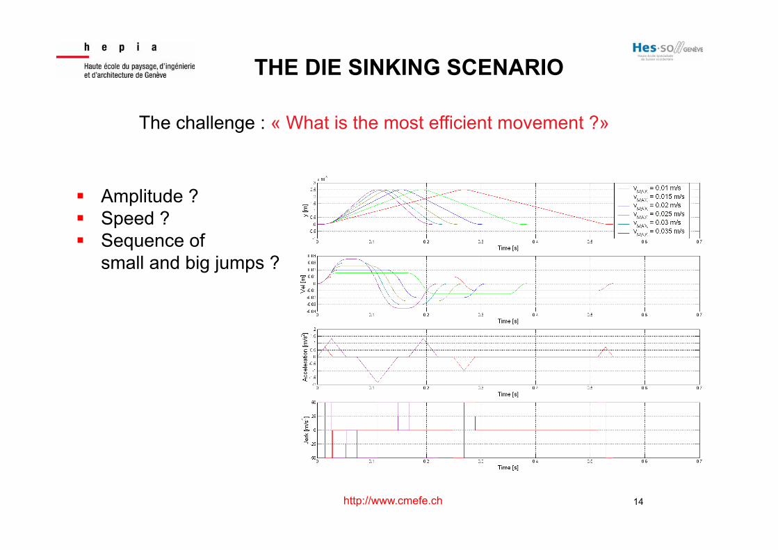
THE DIE SINKING SCENARIO
The challenge : « What is the most efficient movement ?»
! Amplitude ? ! Speed ? ! Sequence of
small and big jumps ?

15 http://www.cmefe.ch
NON-DIMENTIONAL NUMBERS FOR SIMILTUDES
– Reynolds number (inertia vs viscosity effects): – Weber number (inertia vs surface tension effects): – Bond number (gravity vs surface tension effects): – Froude number (inertia vs gravity effects): – Morton number (inertia vs interfacial energy):
Physics: - Viscous flow (injection or parts in motion) - Transport of particles - Gas bubble production
- Bubble movement with possible aggregation

16 http://www.cmefe.ch
GAS BUBBLES EFFECT
Forces acting on a bubble:
• Gas weigth
• Surface tension
• Drag force
• Lift force
• Inertia (or added mass)
• Archimede
• Momentum rate of change
Bubble flow modes
Perreira Dias (4)
17 http://www.cmefe.ch
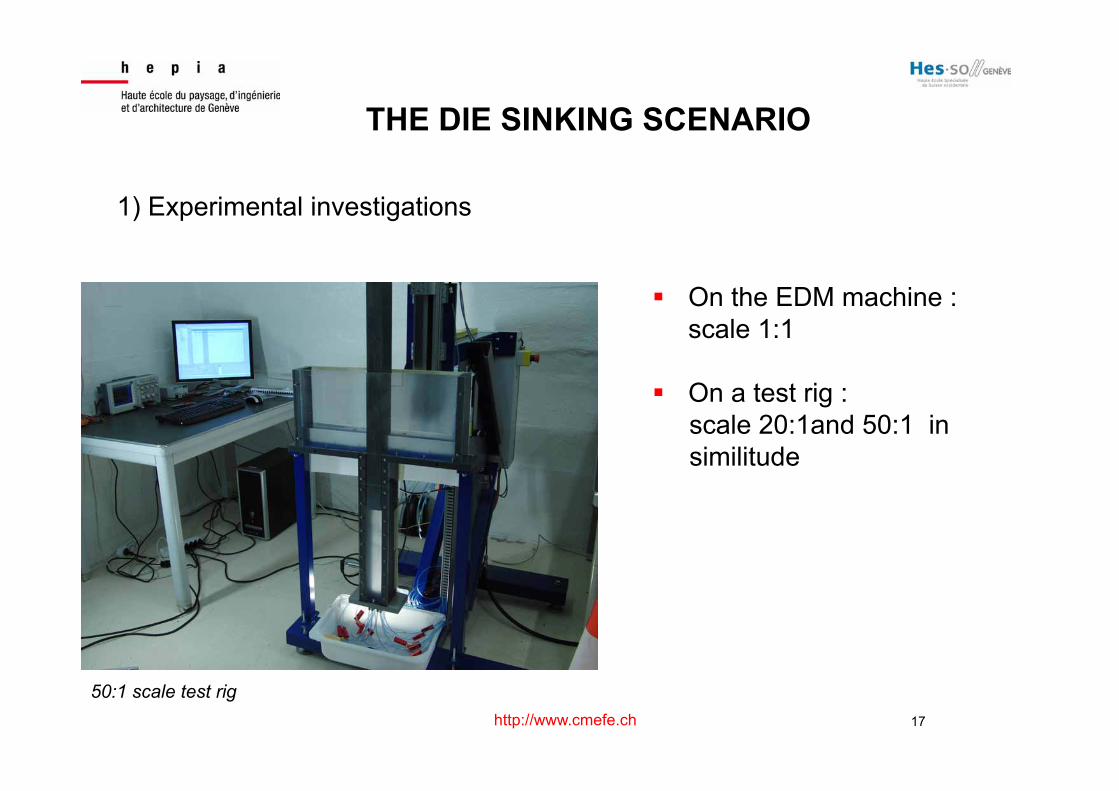
THE DIE SINKING SCENARIO
1) Experimental investigations
! On the EDM machine : scale 1:1
! On a test rig : scale 20:1and 50:1 in similitude
50:1 scale test rig

18 http://www.cmefe.ch
THE DIE SINKING SCENARIO
2) CFD investigations (Fluent) ! Transient model ! 2D and 3D studies ! RANS k-w turbulence model
Some CFD models

19 http://www.cmefe.ch
1. At the beginning of the movement, two symetrical vortices are generated
THE DIE SINKING FLOW ANALYSIS

20 http://www.cmefe.ch
THE DIE SINKING FLOW ANALYSIS
2. The electrode going up, the aspect ratio of the two vortices increases
21 http://www.cmefe.ch
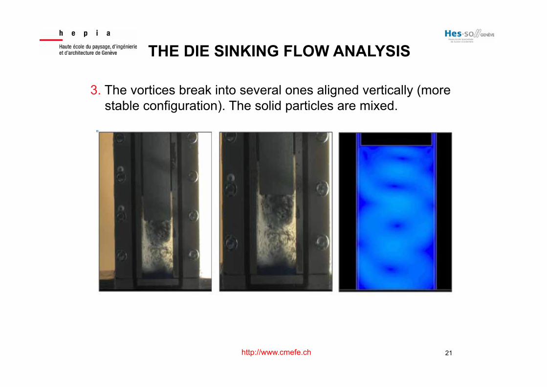
THE DIE SINKING FLOW ANALYSIS
3. The vortices break into several ones aligned vertically (more stable configuration). The solid particles are mixed.

22 http://www.cmefe.ch
THE DIE SINKING FLOW ANALYSIS
4. When the electrode is near 5 to 10 times the width of the cavity, the intensities of the vortices decrease and the particles start to fall. It is not interesting to go higher with the electrode.

23 http://www.cmefe.ch
THE DIE SINKING FLOW ANALYSIS
5. When the electrode goes down, some particles stay under the horizontal part, the others are ejected through the vertical gap.

24 http://www.cmefe.ch

25 http://www.cmefe.ch

26 http://www.cmefe.ch
THE DIE SINKING FLOW ANALYSIS

27 http://www.cmefe.ch
THE WIRE EDM PROCESS ! A dielectric injection is applied continously by 1 or 2 nozzles ! Idea : We can improve the production by working on the nozzle design ! We used 3 approaches: theoretical, experimental and CFD
Material
Upper nozzle and wire guide
Dielectric injection Wire in movement (mecanichal tension and electrical potential)
Lower nozzle and wire guide
Dielectric

28 http://www.cmefe.ch
THE DESIGN OF WIRE EDM NOZZLE 1) Experimental investigations
Pressure measurements in the gap

29 http://www.cmefe.ch
-800
-700
-600
-500
-400
-300
-200
-100
0
100
0 5 10 15 20 25 30 35 40 45
P-Pa
tm (m
bar)
Depth (mm)
Measured pressure in fontcion of depth (z = 0.25 mm) 50 mm high part
a
b
c
d
e
f
g
THE DESIGN OF WIRE EDM NOZZLE

30 http://www.cmefe.ch
THE DESIGN OF WIRE EDM NOZZLE
Annular vortices are generated
31 http://www.cmefe.ch
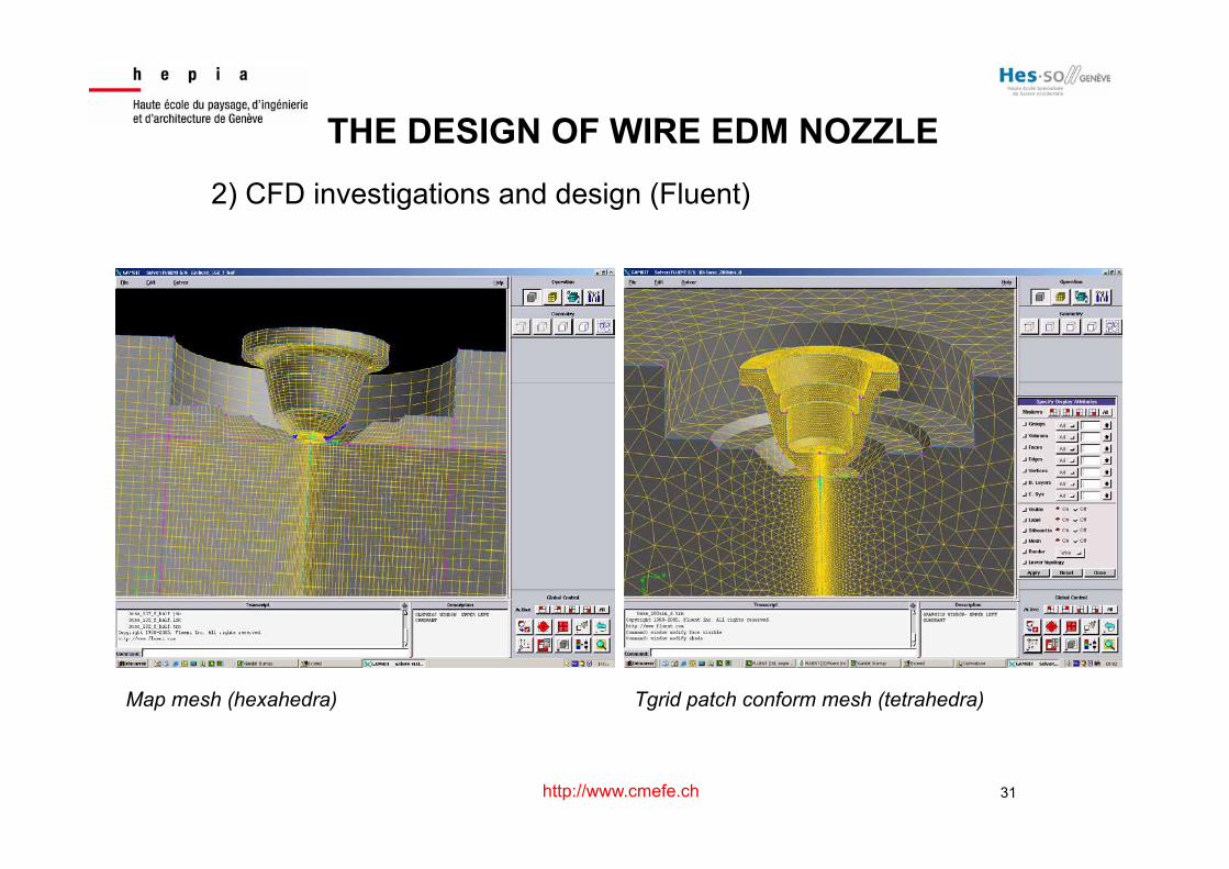
THE DESIGN OF WIRE EDM NOZZLE 2) CFD investigations and design (Fluent)
Map mesh (hexahedra) Tgrid patch conform mesh (tetrahedra)

32 http://www.cmefe.ch
THE WIRE EDM SCENARIO
! Free jet in the dielectric (without part)
Jet speed in m/s

33 http://www.cmefe.ch
• Jet during production (with part) The maximal speed can reach 30 m/s The flow is unstable at the slot entry
Jet speed in m/s
CFD INVESTIGATIONS
Flow understanding leads to nozzle design optimisation

34 http://www.cmefe.ch
! Some nozzle prototypes have been produced using rapid prototyping techniques
3D systems machine
PRODUCTION OF PROTOTYPES
Protoype nozzle in resin

35 http://www.cmefe.ch
! Very high speed jets give flow induced vibrations acting on the wire. The best nozzle found is one still having a part of pressure energy at the end. Difficulties to design a standard nozzle !
! The distance between the nozzle and the part remains a production parameter !
! The production speed obtained practically on a WEDM machine is then dependent of the part geometry (not only the part thickness)
FINAL RESULTS
! Production speed measurements have shown an increase until 20% if an efficient nozzle design is used
! New ways for the gap cleaning are under
investigations. They include a nozzle design / wire movement optimisation.
36 http://www.cmefe.ch
Thanks, questions ?
Patrick Haas, Prof. HES hepia – cmefe Groupe de compétences en mécanique des fluides et procédés énergétiques