Embed Size (px)
Citation preview
Hydroelectric power plants Hydroelectric power plants can drive from a water stream or accumulation reservoir.
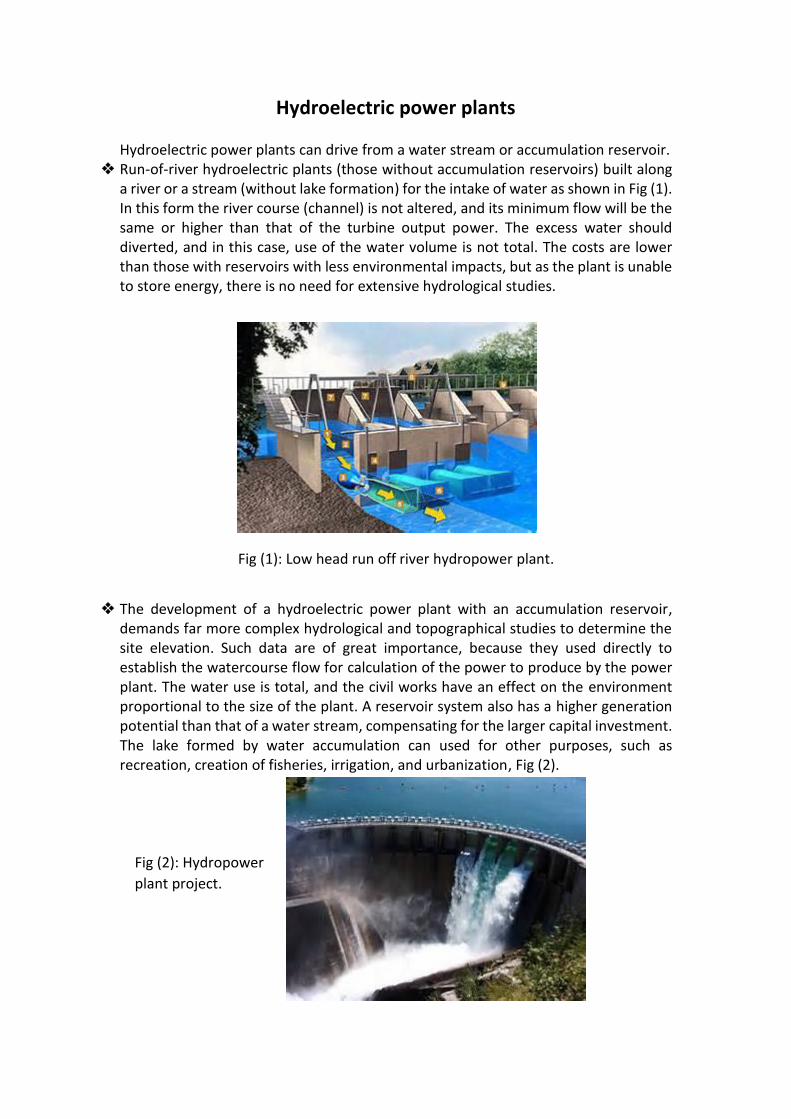
Run-of-river hydroelectric plants (those without accumulation reservoirs) built along a river or a stream (without lake formation) for the intake of water as shown in Fig (1). In this form the river course (channel) is not altered, and its minimum flow will be the same or higher than that of the turbine output power. The excess water should diverted, and in this case, use of the water volume is not total. The costs are lower than those with reservoirs with less environmental impacts, but as the plant is unable to store energy, there is no need for extensive hydrological studies.
Fig (1): Low head run off river hydropower plant.
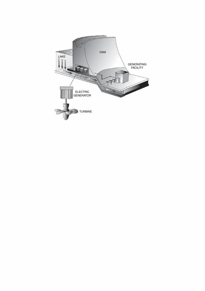
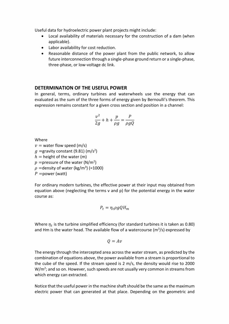
The development of a hydroelectric power plant with an accumulation reservoir, demands far more complex hydrological and topographical studies to determine the site elevation. Such data are of great importance, because they used directly to establish the watercourse flow for calculation of the power to produce by the power plant. The water use is total, and the civil works have an effect on the environment proportional to the size of the plant. A reservoir system also has a higher generation potential than that of a water stream, compensating for the larger capital investment. The lake formed by water accumulation can used for other purposes, such as recreation, creation of fisheries, irrigation, and urbanization, Fig (2).
Fig (2): Hydropower
plant project.
Useful data for hydroelectric power plant projects might include:
Local availability of materials necessary for the construction of a dam (when applicable).
Labor availability for cost reduction.
Reasonable distance of the power plant from the public network, to allow future interconnection through a single-phase ground return or a single-phase, three-phase, or low-voltage dc link.
DETERMINATION OF THE USEFUL POWER In general, terms, ordinary turbines and waterwheels use the energy that can evaluated as the sum of the three forms of energy given by Bernoulli’s theorem. This expression remains constant for a given cross section and position in a channel:
𝑣2
2𝑔+ ℎ +
𝑝
𝜌𝑔=
𝑃
𝜌𝑔𝑄
Where 𝑣 = water flow speed (m/s) 𝑔 =gravity constant (9.81) (m/s2) ℎ = height of the water (m) 𝑝 =pressure of the water (N/m2) 𝜌 =density of water (kg/m3) (=1000) 𝑃 =power (watt) For ordinary modern turbines, the effective power at their input may obtained from equation above (neglecting the terms v and p) for the potential energy in the water course as:
𝑃𝑡 = 𝜂𝑡𝜌𝑔𝑄𝐻𝑚 Where 𝜂𝑡 is the turbine simplified efficiency (for standard turbines it is taken as 0.80) and Hm is the water head. The available flow of a watercourse (m3/s) expressed by
𝑄 = 𝐴𝑣 The energy through the intercepted area across the water stream, as predicted by the combination of equations above, the power available from a stream is proportional to the cube of the speed. If the stream speed is 2 m/s, the density would rise to 2000 W/m2; and so on. However, such speeds are not usually very common in streams from which energy can extracted. Notice that the useful power in the machine shaft should be the same as the maximum electric power that can generated at that place. Depending on the geometric and
material dimensions used in the machines and piping of the power plant, this electric power can be determined in kilowatts (η=0.6; 𝜌=1000 kg/m3; g=9.81 m/s2), approximately, by
𝑃 = 6𝑄𝐻 𝑘𝑊/𝑚2 Where H is the gross head (m), that is, the difference between the levels of the crests of water in the reservoir (dam) and the river at the powerhouse site. The pump flow and pumping manometric height can calculated, respectively, by
𝑄𝑏 = 0.75 𝑄 and
𝐻𝑏 = 0.55𝐻
Specification of Pipe Losses There are four basic causes of losses in pipes conducting water or any viscous fluid from a higher potential point, say a water dam, to a lower potential point, such as a hydraulic turbine. The four causes are the specific mass 𝜌 of the fluid (kg/m), the average speed v(m/s), the pipe diameter D(meters), and the viscosity coefficient µ (kg/m.s), all related quantitatively by the Reynolds number:
𝑅 =𝜌𝑣𝐷
µ
For the specific case of water, which is the basis for all hydraulic turbines, 𝜌=1000 kg/m and µ=10-3kg/m.s at 20oC. The Reynolds number is a nondimensional number; it does not depend on a system of units. The number used to establish the speed limit at which a fluid can run in a pipe without turbulent flow. It is common practice to establish R within the following limits: for R=2000 and below, the flow is laminar; for R from 2000 to 3000, the flow is unstable; and for R above 3000, the flow is turbulent. Pipe losses are extremely sensitive to the diameter of the pipe not only by affecting the Reynolds number inversely but also by contributing to the increase in velocity of the fluid and the associated losses. It is a complex task to quantify these contributions mathematically, so it is usual in hydrology studies to unite all losses in a head equivalent hi. The equivalent is defined as a term proportional to the pipe length and friction and to the kinetic energy given by Bernoulli’s expression and inversely proportional to the pipe diameter. This expression known as the Darcy–Weisbach formula:
ℎ𝑖 = 𝜆𝑙
𝐷
𝑣2
2𝑔
The friction factor λ is provided by the pipe manufacturer. The final value of practical interest is then effective hydraulic gradient, expressed as
∇ℎ =ℎ + ℎ𝑖
𝑙
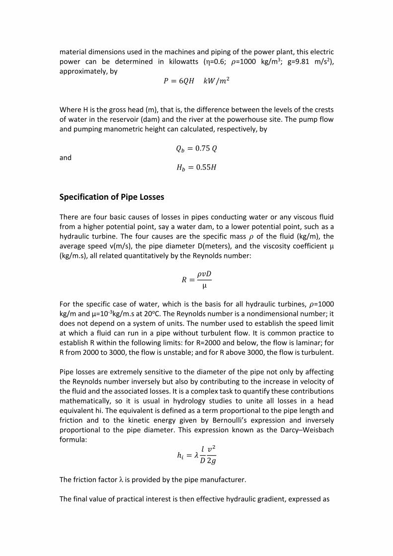
WATERWHEELS Waterwheels are quite primitive and simple machines, usually built of wood or steel, with shovels of steel blades fixed regularly around their circumference as shown Fig (3). The water pushes the shovels tangentially around the wheel. The water does not exert thrust action or shock on the shovels as is the case with turbines. The water thrusting on the shovels develops torque on the shaft, and the wheel rotates. As one can infer, such machines are relatively massive, work with low angular speeds, and are of low efficiency, due to losses by friction, turbidity, incomplete filling of the buckets (or cubes), and other causes. In the case of bucket wheels, considering input and output at the same atmospheric pressure (∆𝑝 =0.0), the effective shaft power becomes
𝑃𝑝 = 𝜂𝜌𝑔𝑄𝐻𝑚
Where η is the efficiency (practical value =0.60) and Hm is the head difference between crests (upper surface) of the water stream at the input and output of the channel. Notice that, the upper bucket wheel diameter is the minimum head of the water required to move it, whereas the lower bucket wheel is adapted for smaller heights. The use of waterwheels for electric power generation presents some important advantages:
1. production and conservation goals are easily met; 2. operation is not affected by dirty water or by solids in suspension; and 3. their motor torque value is aided in a certain way with an increase in load
because during the decreased rotation under load, the buckets have more time to fill with water and thus increase the moment applied on the machine shaft.
The largest disadvantage of waterwheels is 1. Their low angular speed of operation, which causes the generator to work with
speed multipliers at high reduction rates, thus resulting in appreciable losses of energy.
2. When the system needs any speed regulation, which could complicate such a simple energy-generating system.
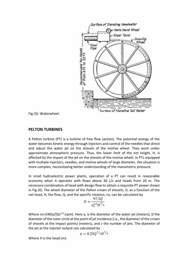
Fig (3): Waterwheel.
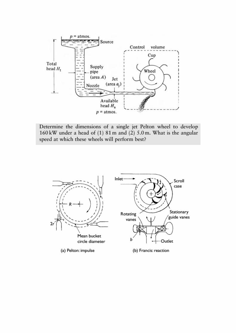
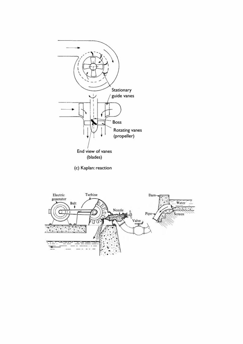
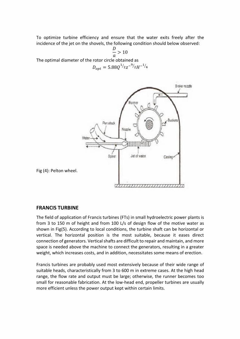
PELTON TURBINES A Pelton turbine (PT) is a turbine of free flow (action). The potential energy of the water becomes kinetic energy through injectors and control of the needles that direct and adjust the water jet on the shovels of the motive wheel. They work under approximate atmospheric pressure. Thus, the lower limit of the net height, H, is affected by the impact of the jet on the shovels of the motive wheel. In PTs equipped with multiple injectors, needles, and motive wheels of large diameter, the situation is more complex, necessitating better understanding of the manometric pressure. In small hydroelectric power plants, operation of a PT can result in reasonable economy when it operates with flows above 30 L/s and heads from 20 m. The necessary combination of head with design flow to obtain a requisite PT power shown in Fig (4). The wheel diameter of the Pelton crown of shovels, D, as a function of the net head, H, the flow, Q, and the specific rotation, ns, can be calculated by
𝐷 =97.5𝑄
𝑛𝑠0.9𝐻
14⁄
Where ns=240(a/D)z1/2 (rpm). Here a, is the diameter of the water jet (meters), D the diameter of the rotor circle at the point of jet incidence (i.e., the diameter of the crown of shovels at the impact points) (meters), and z the number of jets. The diameter of the jet at the injector output can calculated by
𝑎 = 0.55𝑄1
2⁄ 𝐻1
4⁄ Where H is the head (m).
To optimize turbine efficiency and ensure that the water exits freely after the incidence of the jet on the shovels, the following condition should below observed:
𝐷
𝑎> 10
The optimal diameter of the rotor circle obtained as
𝐷𝑜𝑝𝑡 = 5.88𝑄1
2⁄ 𝑧−92⁄ 𝐻−1
4⁄
Fig (4): Pelton wheel.
FRANCIS TURBINE
The field of application of Francis turbines (FTs) in small hydroelectric power plants is from 3 to 150 m of height and from 100 L/s of design flow of the motive water as shown in Fig(5). According to local conditions, the turbine shaft can be horizontal or vertical. The horizontal position is the most suitable, because it eases direct connection of generators. Vertical shafts are difficult to repair and maintain, and more space is needed above the machine to connect the generators, resulting in a greater weight, which increases costs, and in addition, necessitates some means of erection. Francis turbines are probably used most extensively because of their wide range of suitable heads, characteristically from 3 to 600 m in extreme cases. At the high head range, the flow rate and output must be large; otherwise, the runner becomes too small for reasonable fabrication. At the low-head end, propeller turbines are usually more efficient unless the power output kept within certain limits.
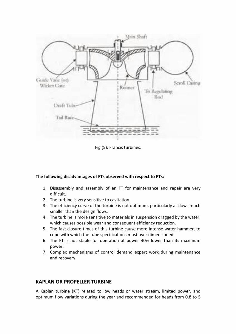
Fig (5): Francis turbines. The following disadvantages of FTs observed with respect to PTs:
1. Disassembly and assembly of an FT for maintenance and repair are very difficult.
2. The turbine is very sensitive to cavitation. 3. The efficiency curve of the turbine is not optimum, particularly at flows much
smaller than the design flows. 4. The turbine is more sensitive to materials in suspension dragged by the water,
which causes possible wear and consequent efficiency reduction. 5. The fast closure times of this turbine cause more intense water hammer, to
cope with which the tube specifications must over dimensioned. 6. The FT is not stable for operation at power 40% lower than its maximum
power. 7. Complex mechanisms of control demand expert work during maintenance
and recovery.
KAPLAN OR PROPELLER TURBINE
A Kaplan turbine (KT) related to low heads or water stream, limited power, and optimum flow variations during the year and recommended for heads from 0.8 to 5
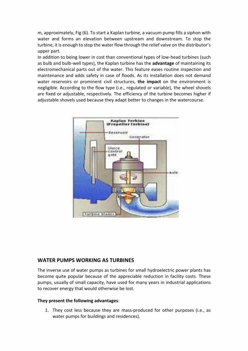
m, approximately, Fig (6). To start a Kaplan turbine, a vacuum pump fills a siphon with water and forms an elevation between upstream and downstream. To stop the turbine, it is enough to stop the water flow through the relief valve on the distributor’s upper part. In addition to being lower in cost than conventional types of low-head turbines (such as bulb and bulb-well types), the Kaplan turbine has the advantage of maintaining its electromechanical parts out of the water. This feature eases routine inspection and maintenance and adds safety in case of floods. As its installation does not demand water reservoirs or prominent civil structures, the impact on the environment is negligible. According to the flow type (i.e., regulated or variable), the wheel shovels are fixed or adjustable, respectively. The efficiency of the turbine becomes higher if adjustable shovels used because they adapt better to changes in the watercourse.
WATER PUMPS WORKING AS TURBINES
The inverse use of water pumps as turbines for small hydroelectric power plants has become quite popular because of the appreciable reduction in facility costs. These pumps, usually of small capacity, have used for many years in industrial applications to recover energy that would otherwise be lost. They present the following advantages:
1. They cost less because they are mass-produced for other purposes (i.e., as water pumps for buildings and residences).
2. Their acquisition time is minimal because they have a wide variety of commercial standards and are available in hardware stores and related shops.
However, they have a few disadvantages: They have slightly reduced efficiency compared to the same head height used for water pumping, and they are sensitive to the cavitation characteristics and operating range.