Embed Size (px)
Citation preview

RBI Water Heaters 2007 DOC #RBIFIIIHN
260 N. Elm St.
Westfield, MA 01085
04/24/15 1
RBI Futera III Series Firmware Revision Sheet
Revision 3.51- 3.52 4-24-2015 Release
1. Removed the running restriction when calling a Base Load boiler from a Member boiler. The
Member boiler does not need to be firing in order to call a Base Load boiler. Provisions on the
Base Load boiler should be checked to allow a system pump to run and any dampers to
open. Failsafe using the Base Load boiler from the Member is automatic. Whenever the Member fails,
the Base Load boiler will be enabled as long as the Member can do so.
The Master boiler still requires a heat demand input in order to control a Base Load boiler
connected to it. Though, the Master boiler does not need to be running. This is to ensure that the
system pump and damper will be enabled for the system. The System pump and Damper control
are the main reasons to connect the Base Load boiler to the Master.
Failsafe on the Master boiler will occur if there is a Heat Demand input present, there are no
available boilers to fire, and the Master has failed.
2. The Spare 4 interlock (USER) is now used to facilitate a condensate switch.
Revision 3.50 11-12-2014 Release
1. Fixed an issue when using the HeatNet control on a stand-alone boiler. The local pump could
remain on after the heating cycle has completed. The local pump will now always shut off
when the heating cycle completes.
Revision 3.48-3.49 9-July – 2014 Release
1. The ADVANCED SETUP:MODULAR BOILER SET:ADD BOILER DELAY setting
showed 120 seconds instead of 30 seconds. This was a display issue, the 120 seconds
displayed is actually 30 seconds. The setting now shows 30 seconds for intervals.
Revision 3.47 2– April – 2014 Pre-Release
2. Limited the SETUP:AUX FUNCTIONS:HEAT EXCHANGER:TEMP < 140F setting to go
no lower than 135F.
3. Fixed an issue with saving the MIN OFF TIME. Values larger than 4 minutes were not saved.
Revision 3.46 7 – March – 2014 Pre-Release
1. Added the fault error codes to the upper byte of the BOILER STAGECONTROL bits. This is
to allow HeatNet online to properly decode a fault.
2. Increased the maximum ADD BOILER delay time from 15 minutes to 1 hour due to requests.
3. Added the ability for a boiler to take itself offline from HeatNet when the return water
temperature is below a threshold. This feature would primarily be used to keep non
condensing boilers from firing in a condensing situation. It may be used with the priority 1 &
2 modes to keep only condensing boilers running when return temperatures are low.

RBI Water Heaters 2007 DOC #RBIFIIIHN
260 N. Elm St.
Westfield, MA 01085
04/24/15 2
If the boiler is isolated by a pump/valve, a HeatNet V3 board can be used as a Master boiler to
supply the return temperature. The V3 board has the ability to measure the system return temp
and send it to each boiler via the HeatNet network. The version 2 board (this firmware) can
then use it to view the system return temperature and make itself, not available to fire by
HeatNet. While the boiler is in this “not available” state, it can still be fired locally and
failsafe is still available.
If the Master boiler is a version 2 board the Master will always transmit its return temperature
to all boilers. If the Master is set to Priority 1 and all other non-condensing boilers are set to
Priority 2 the Master should always remain on if there is a call for heat. This requires that the
Priority 1 boiler be set up to start first and stop last. This method should always send a valid
return temperature to the Member boilers. This method can also be used with a version 3
board, but a system return sensor is preferred if available.
When this condition is in effect, the STATUS screen will indicate “blr offline”.
SETUP:AUX FUNCTIONS:HEAT EXCHANGER:LOW TEMP:
OFF No check is made to the return temperature – boiler remains online
RETURN Uses the boilers own return sensor (No pump /valve present)
SYS RETURN Uses the System Return temp received from the Master Boiler.
SETUP:AUX FUNCTIONS:HEAT EXCHANGER:TEMP < 140F
Adjustable threshold temperature below which the boiler will take itself offline.
1 degree F of hysteresis is provided so as to not toggle offline-online at threshold temp.
Revision 3.45 20 – August – 2013 Pre-Release
1. Fixed an issue with taking the Member boiler offline. If a Member boiler is running in
Lowfire or being directly Modulated using a 4-20mA or 0-10V signal, the Master would still
see the boiler as available to fire. This has been corrected.
Revision 3.44 29 – July – 2013 Pre-Release
1. The previous version had an issue when the extended post purge of the blower would not keep
combustion damper open long enough. The Combustion Air Damper now closes
immediately after the extended post purge ends.
Revision 3.42 24 – June – 2013 Release
1. Minimized a Calibration display error when switching to running mode from calibration
mode. Also fixed a display error when switching from Heat Demand to Low Fire. The Low
Fire value will now be displayed.
2. Reduced code size to allow for PVC, and Spanish/Russian version builds.
Revision 3.41 6 – November – 2012 Release
1. The previous version introduced a timing issue that caused USB drive firmware updates to
fail on some boards. In order to update the firmware, it is necessary to use a USB cable and
the HeatNet Firmware Update PC software. This issue is fixed with this release.

RBI Water Heaters 2007 DOC #RBIFIIIHN
260 N. Elm St.
Westfield, MA 01085
04/24/15 3
Revision 3.401 24 – January – 2012 Release
1. When using a single boiler with a base load boiler the Linked/Common damper did not
operate properly. This issue is fixed with this release.
2. When using a base load boiler and there is no Member or Master boiler available to fire, the
Modulation % setting to start the base load boiler will not work. This is due to the Modulation
value going to 0 when all boilers are in a failed condition. With this release, the Master’s base
load boiler will automatically fire if the Master boiler sees this condition. This new feature
will not work if a stand-alone/ Member boiler (no header sensor) is used with a base load
boiler.
3. During a UV sensor 24 Hour shutdown test, the Fail bit would be temporarily set in the
Modbus status register. This has been corrected with this release.
Revision 3.39 18 – AUGUST – 2011 Release
1. Extended the adjustment range of MIN RUNTIME to 750 hours (31 days) in ADVANCED
SETUP:FIRING MODE:MIN RUNTIME. The old setting was limited to 10 days when
TRUE ROTATION MODE is used.
2. Added the 0-10Vdc control signal output J4.3 (signal) and J4.7 (ground). This signal is output
by the Master boiler as a percent function of the number of boilers running and can be used to
set the speed of a System Pump using a Variable Frequency Drive. Two wires are required
and need to be inserted into the J4.3 and J4.7 positions to access this signal.
Note: This signal has a step response and is not linear to the system or boiler’s input firing
rate.
The output signal is proportionally mapped to % using the equation:
%VFD = (boilers running/total boilers)
The %VFD represents the stepped percentage of boilers running where:
0Vdc = 0% to 10Vdc = 100%
If there are (6) boilers in a system and (2) are running, the control signal = 33% or 3.3Vdc.
This signal could then be applied to a system pump’s VFD to control the speed of the pump
relative to how many boilers are firing. The VFD would need to be set appropriately to allow
the correct flow through each boiler.
In low volume systems sudden temperature changes may occur when the flow is stepped up or
down by a large percentage. In these situations the ADAPTIVE MOD may need to be
disabled and the ORIGINAL KN method used. Other adjustments may also be required (see
manual).
Currently, no failsafe mode is available in the event the Master boiler’s control fails. If this
method is employed, a failsafe boiler could be used to override the control signal and enable
the system pump’s VFD using some external wiring.
Revision 3.38 10 - JUNE– 2010 Release
1. Allow Spanish language build.

RBI Water Heaters 2007 DOC #RBIFIIIHN
260 N. Elm St.
Westfield, MA 01085
04/24/15 4
2. Changed the minimum temperature setting from 150F to 190F on the SETUP:OUTDOOR
AIR RESET:SET OA SETPOINTS:WATER TEMP at HIGH OA TEMP. This change was
done to allow greater range.
3. Added the ability to change the DHW water setpoint along with viewing other variables via
Modbus, BACnet, and LonWorks.
1) Added Read/Write DHW Setpoint. The DHW setpoint is located address 40018.
2) Updated description of Setpoint Timer (a write to any read/write variable now
reloads).
3) Updated description of System Modulation
4) Added Boiler## Status4 Flags
5) Added Boiler## DHW Temperatures
6) Added Boiler## Modulations
7) Added Operating Setpoint
See online Modbus register documentation.
4. Added a Modulation Maximum hold off when using the AA terminal for High Fire and when
using the 4-20 mA input for direct modulation. When these demands for heat are used, the
maximum modulation the boiler can obtain when first starting is equal to the; ADVANCED
SETUP: MODULAR BOILER SET: MOD MAX – LAST FIRE:. The timer value
ADVANCED SETUP: MODULAR BOILER SET:ADD BOILER DELAY is used in
conjunction to limit the modulation for this amount of time. Once the boiler has fired and the
ADD BOILER DELAY time expires, the full modulation is available. This change is a
protective means for extending the life of the heat exchanger which may consistently be
exposed to thermal stress.
Revision 3.37 P 19 - Nov– 2010 Release
1. This firmware version is only available for Fusion boilers, and allows the use of an approved
PVC vent pipe. It requires a flue temperature sensor and high limit mounted to a vent pipe
adaptor which is available from the factory. The flue temperature sensor must be wired to
J10B, pins 3 and 4 marked “Spare 2”. The boiler will not operate if the flue temperature
sensor is not connected.
The control monitors the flue temperature and attempts to keep it below an operating limit
by reducing the boiler’s input. The control will limit the boiler’s input starting at a flue
temperature of 179°F. If the flue temperature continues to rise, the input will be further
reduced to a maximum of the MIN FIRE until the control limit of 184°F is reached and the
boiler shuts down. Once the flue temperature falls below 174°F the boiler will recycle. If
the high limit of 195°F (+0, -5%) is reached the boiler will shut down and a manual reset
will be required.
Revision 3.37 9 - Jun– 2010 Release
1. An issue exists when using a Flash Drive to update the firmware. Due to an end of life
component in positions U20 and U2, a substitute was used. This firmware version applies to
version 2.x control boards manufactured between 3/8/10 to 6/7/10. If the U20 component is
manufactured by Microchip (part number and symbol on chip: 25LC256, ), this
firmware release needs to be downloaded via USB cable and a PC/laptop. The Flash Drive
RBI Water Heaters 2007 DOC #RBIFIIIHN
260 N. Elm St.
Westfield, MA 01085
04/24/15 5
loader may not work with earlier firmware versions if this chip is present. This release
corrects this issue.
Revision 3.36 29 - Mar– 2010 Release
1. Corrected an issue when writing the setpoint using Modbus, LonWorks, or BACnet. If the
setpoint is written repeatably within a few minutes, a condition may arise where the real time
clock will not increment the time. This has been corrected with this release.
Revision 3.35 19 - MAR – 2010 Release
1. Added the ability to control a local pump using a Variable Frequency Drive. To enable this
feature: SETUP:PUMP OPTIONS:LOCAL PUMP PUMP/VALVE OPTION:LOCAL
PUMP VFD: ON. Setting this Option to ON will map the control signal on J4 pins 1+ and
5- to the modulation rate. (2) wires need to be run from J4.1+ and J4.5- to the VFD’s input
connection. Ensure that the J18 shunt jumper on the control board is in position PWM/0-10.
This will allow the local pump to run at speeds relative to the firing rate of the boiler
2. Added a failsafe mechanism for Base Loading using the J4 relay. If there are no boilers
available to fire and there are no boilers in local override, and there is a call for heat, The J4
Base Load relay will close. If a boiler becomes available and needs to fire, the Base Load
boiler will remain firing until the temperature exceeds the band.
3. Added the ‘E’ suffix after the file name to indicate that the version is English menus. The
‘R’ version will indicate Russian.
Revision 3.34 25 - JAN – 2010 Release
1. Corrected a display issue caused in Version 3.43 when there is no call for heat and the
System Flow switch is open. The message “HEAT:OPL*” would be displayed. This has
been corrected to display “STANDBY”. Also: When a delayed open interlock was in process
of timing out “HEAT:OPL” was displayed until the delay expired. This was corrected to
display “HEAT:INTLK” until the interlock fault delay time completed.
2. Corrected a display issue during Warm Weather shutdown. “HEAT:OPL” would be
displayed if the operating limit was tripped and Warm Weather Shutdown was entered. The
“HEAT:OPLM” would be displayed until WWS exited. This has been corrected.
3. A condition exists where the Heat Net control will close the last interlock to start the ignition
control and the START interlock relay K3 or K1’s contact would stick open. While this is
rare, the boiler will lock out and require a manual power cycle. This failure mechanism would
be displayed as “HEAT:WAIT” forever or until power cycled.
In order to minimize this impact and downtime, a retry algorithm of (5) attempts has been
added. If this condition occurs, an ‘*’ will be displayed and the status screen will display
“retry strt” indicating it has attempted a restart to “un-stick by electrically tapping” on the K3
and K1 relays. During this restart period, the restart timer is loaded with the local pump post
purge time + 3 seconds. This is to ensure the water flow through the boiler has ceased and the
flow switch is open, thus removing the power to the K3 interlock relay. If this does not work,
the control will attempt up to (4) more retries before locking out. This method to electrically
tap the K3 relay may not work completely in systems without local valves/pumps since a way
of opening the interlock circuit needs to occur. The K1 relay will always get “tapped”.

RBI Water Heaters 2007 DOC #RBIFIIIHN
260 N. Elm St.
Westfield, MA 01085
04/24/15 6
If this condition occurs on Member boilers the Run Screen will display STANDBY * and
the Status Screen will display “rtry start” each time the retry occurs and will lockout with the
“CALL SERVICE” message displayed.
A log entry of "START FAILED, RETRY " will also be entered for each attempt.
4. Identified an issue where the Outdoor Air sensor and other sensors failed as OPEN or
SHORTED when they were not present (version 1 control boards, BLUE). Fast AC line
power cycling/brownout resets may cause the control to erroneously detect a phantom chip on
a version 1 board that is only present on version 2 boards. Detection of version 1 and version
2 boards has been adjusted to account for this condition. This issue does not exist on version 2
boards.
5. Corrected a display issue while in the Run Screen with DELTA TEMP. Base temperature
calculations are always performed in degrees F and then converted to degrees C. If the
temperature scale is set to C, the difference F temperature was being converted to C. Now the
DELTA TEMP is calculated as the difference temperature in degrees C rounded to the nearest
degree.
This display issue was also present in the HEAT EXCHANGER:EXCHGR DELTA menu
and the fault message when the delta T was exceeded.
6. Fixed a display issue when erasing the temperature pointer in the main screen.
7. Added the MIN RUNTIME to the ADVANCED SETUP:FIRING MODE. This setting replaces
the USE LEAD BOILER menu item. Prior to this change, when using TRUE Runtime or
MIXED fire rotation, the boilers were rotated based on how many seconds elapsed between
boilers (typically a 3 minute difference). This was determined to cause boilers to rotate too
quickly. This change will allow a boiler to rotate only once it has exceeded the time in hours
set in MIN RUNTIME. This change allows a boiler that has already fired and warmed up to
fire again when it’s minimum runtime has not been met. Some limitations may be in effect
and the most optimal boiler to fire next with the least runtime may not occur.
The “USE LEAD BOILER” menu is replaced by setting the SETUP:BOILERS:LEAD
BOILER to a 0 (equivalent to NO) and will disable the use of the LEAD BOILER. Setting it
to a boiler number will enable that Lead Boiler. If the heating application uses the Lead
boiler, the lead boiler may need to be set, since the default value after loading this revision is
SETUP:BOILERS:LEAD BOILER 0.
Revision 3.33 16 - JAN – 2010 Release
This revision brings (2) major features to the Heat Net control.
A. The first feature uses Heat Net to allow mixing of CONDENSING, NON-
CONDENSING, BASE LOAD, or other combination of (2) functional boiler
types. This feature provides conditional firing based on a “priority set” of boilers
utilizing (2) priority levels.
B. The second feature allows BASE LOADING of boilers without Heat Net. This
feature provides the ability to control (1) base load boiler using an OPTION
relay (version 2.x controls only). It can also be used with ‘A’ above for more
control configurations.

RBI Water Heaters 2007 DOC #RBIFIIIHN
260 N. Elm St.
Westfield, MA 01085
04/24/15 7
The Heat Net method of BASE LOADING also provides for TRUE RUNTIME
rotation, fault detection/reporting, conditional firing of multiple non-condensing
boilers with multiple condensing boilers, and modulating of non-condensing
base load boilers.
1. The first feature: A MIXED boiler priority method may be used to control condensing and
non-condensing, base load, or other boiler sets in a system for optimal performance and
economy. A boiler set can be constructed by simply setting the FIRING PRIORITY on each
boiler (to be in the set) at the same priority. Setting all (example)condensing boilers to the
highest priority of 1, and then setting all (example)non-condensing boilers to a priority of 2,
will create (2) sets of boilers, one condensing and the other non-condensing. Once this is
done, the set of condensing boilers will have a firing order that has a higher priority and is
independent of the other non-condensing set with the lower priority. The boiler set with the
highest priority can then be fired based on the conditional settings menu. The lower priority
set will follow.
A boiler’s firing priority can be designated as such in: “ADVANCED
SETUP:SYSTEM:BOILER TYPE:FIRING PRIORITY : 1” menu on each boiler. A priority
of ‘1’ is the highest priority, a ‘2’ the lowest (default is always 2).
In the above example condensing boilers and non-condensing boilers are used, but other
combinations may also be used. Another example could use (2) small boilers and set them to
Priority 1 and then use (3) large boilers and set them to Priority 2. Using these priority
settings (with the conditions menu), the small boilers can run first during the shoulder months
and the larger boilers can fire last during the colder season (base loading set).
Before the MIXED method can be used, the firing mode on the Master boiler must be set to
MIXED. ADVANCED SETUP:FIRING MODE: MODE: MIXED. Pressing the SELECT key
when the cursor is pointing to MIXED will enter the conditions menu. The Start and Stop
conditions for starting and stopping priority boiler sets may be configured here. Temperatures
are adjustable.
Once the conditions menu has been entered, the firing order and stop order of the priority 1
boiler set can be selected based on up to (3) conditions each in the conditional settings menu.
All conditional settings apply to the priority 1 boiler set. When the conditional settings do not
apply to the priority 1 set, the conditional settings will apply to the priority 2 boiler set. The
following is an example using mixed condensing and non condensing boilers:
Condensing boilers may be configured to fire first (set to PRIORITY 1) when:
Prior Priority 1
Condensing (Set)
Prior Priority 2
Non-Condensing (Set)
Master 2 3 4 5
FIRING MODE (MASTER)
MIXED10HRs
MODE
MIN OFF TIMEMIN RUNTIME:
0mPREDICT START : YES
BOILER TYPE (All Boilers in Set)
: 12000,000
FIRING PRIORITY
CONDENSINGBTU IN
YESMASS LOW
BOILER TYPE (All Boilers in Set)
:22000,000
FIRING PRIORITY
CONDENSINGBTU IN
NOMASS LOW

RBI Water Heaters 2007 DOC #RBIFIIIHN
260 N. Elm St.
Westfield, MA 01085
04/24/15 8
A. The Return water temperature is below 130F and condensing occurs.
B. The Outside Air Temperature is above a setpoint determined by the system
configuration. This setpoint ensures that the more efficient condensing boilers
run during shoulder months (Spring and Fall) when minimal heating is required.
Below this setpoint, larger boilers should be brought on first to “base load” the
system.
C. Greater efficiency is required.
Condensing boilers may be configured to stop first (set to PRIORITY 1) when:
A. The Return water temperature is above 130F and condensing is minimized, thus
leaving the larger lower cost boilers running to carry the load.
B. The Outside Air Temperature is below a setpoint determined by the system
configuration. This setpoint ensures that the larger non-condensing boilers run
during the coldest months when maximum heating is required. Above this
setpoint smaller condensing boilers should be brought on first to run the system
as efficiently as possible.
C. Maximum heating is required
START PRIORITY 1 SET: Selections (always the lowest runtime first):
FIRST: The condensing boilers (Priority 1) are always started FIRST
OA T > 15F: The condensing boilers (Priority 1) are started when the OA
temperature is greater than the Mixed Boiler Outdoor Air
Temperature setting.
RET < 140F: The condensing boilers (Priority 1) are started when the Return
water temperature is less than the Mixed Boiler Return temperature
setting.
Note: The condensing boiler set (Priority 1) has a higher priority to
fire when one of these conditions is met.
STOP PRIORITY 1 SET: Selections (always the highest runtime first):
LAST: The condensing boilers (Priority 1) are always stopped LAST.
OA T < 15F: The condensing boilers (Priority 1) are stopped first when the OA
temperature is less than Mixed Boiler Outdoor Air Temperature.
RET > 140F: The condensing boilers (Priority 1) are stopped first when the
Return water temperature is greater than the Mixed Boiler Return
temperature.
Note: The condensing boiler set (Priority 1) has a higher priority to
stop when one of these conditions are met.
START PRIORITY 1SET : FIRST
°OA T < 15STOP PRIORITY 1SET :
RBI Water Heaters 2007 DOC #RBIFIIIHN
260 N. Elm St.
Westfield, MA 01085
04/24/15 9
Any combination of Start Conditions and Stop Conditions can be used to optimize the mixing
of condensing (Priority 1) and non-condensing boilers (Priority 2) for best
performance/economy.
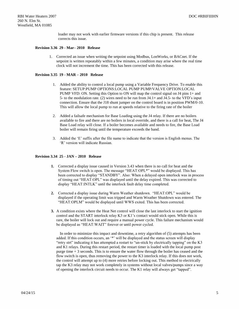
The default settings for the start and stop conditions of the condensing set are:
The default start setting always starts the condensing boilers (Priority 1 example) first, except
for the lead boiler setting. The lead boiler will always start first if enabled, unless there is a
boiler already running (this includes a Member boiler in LOCAL). The default stop condition
setting always stops the condensing boilers (Priority 1) last.
Base load boilers can be mixed in the same way as condensing and non-condensing boilers.
The base load boiler(s) can be prioritized in one set (say, priority 2) and non-base load boilers
(priority 1) the other set. The non-base load boilers can then be set to fire first and once they
are all firing, the base load boiler would fire.
To minimize the cycling of a large base load boiler, consider using the stop condition. Change
it to the OA T < 15F (Outside Air Temperature) condition. This setting may be used to stop
the priority 1 boiler set when the OA T drops below the OA T setpoint, thus leaving the large
base loaded boiler on and shutting off the condensing boilers first. This is also true when
using the OA T setting to start the priority 1 boiler set when the OA T is above the start
setpoint. To use temperatures as start and stop conditions the system design temperatures
must be known.
Starting Boilers:
When a boiler is to be fired (water temp is below the heating band), the Master checks the
Heat Net boilers it has available. The Master boiler then looks at which boilers are returning
priority firing status (set on a boiler in: (ADVANCED SETUP:SYSTEM:BOILER
TYPE:PRIORITY : 1). If the Start condition is met (ADVANCED SETUP:FIRING MODE:
MODE: MIXED:SET FIRS T(example), the Master or Member boiler that is configured as
PRIORITY 1, with the lowest runtime, will be fired FIRST(example).. As long as the start
condition is met, all PRIORITY 1 set of boilers will fire based on runtime. Once all
PRIORITY 1 set of boilers have fired, the PRIORITY 2 set of boilers will fire based on
runtime. If the Start condition changes and/or is not met (such as with: OA T or RET temp),
the PRIORITY 2 set of boilers will fire first/next based on runtime.
Stopping Boilers:
When a boiler is to be stopped (water temp is above the heating band), the Master checks the
Heat Net boilers it has available. The Master boiler then looks at which boilers are returning
priority firing status (set on a boiler in: (ADVANCED SETUP:FIRING MODE: MODE:
MIXED:SET LAST(example) If the Stop condition is met, the Master or Member boiler that
is configured as PRIORITY 1 with the highest runtime will be stopped LAST (example). As
long as the stop condition is met, all remaining PRIORITY 1 set of boilers will stop based on
runtime. If the Stop condition changes and/or is not met (such as with: OA T or RET temp),
the PRIORITY 2 set of boilers will stop first/next based on their highest runtime.
2. Added the ability to control (1) base load boiler using the K8 Relay contacts on J4 pins 2 & 6.
In order to connect to this plug, (2) wires with pins are required and inserted in J4. This ability
START PRIORITY 1FIRSTSET :
STOP PRIORITY 1LASTSET :

RBI Water Heaters 2007 DOC #RBIFIIIHN
260 N. Elm St.
Westfield, MA 01085
04/24/15 10
requires these (2) flying leads (loose wires available from the factory) to be inserted into J4,
pins 2 & 6. These (2) wires then make up the Normally Open contacts. . This feature also
requires a rev 2.x control board and can be used on Master or Member boilers. It is not
applicable in version 1.x control boards (no relay). The relay K8, with contact connections on
J4.2 & J4.6 has a rating of: 0.1 to 1 Amp.
If the base load boiler is of the modulating type, a 4-20mA signal is also provided on J4 pins 1
and 5. J18 will then need to be set to 4-20mA. Two additional wires (available from the
factory) will need to be added to the J4 pins at 1 & 5. Pin 1 is the + output of the 4-20mA
transmitter, and pin 5 is the – output. This modulating control signal is used to modulate the
base load boiler along with the Heat Net boilers in parallel. The ADAPTIVE MOD does not
function when the base load boiler is added to lower the modulation rate of all boilers. The
PID will adapt to the newly fired base load boiler and lower its modulation rate with the
increase in water temperature.
Enable the base load feature by setting:
2. ADVANCED SETUP:SYSTEM:OPTION to BASE LOAD. This setting instructs
the OPTION Relay to be used as control for a Base Load Boiler.
3. The ADVANCED SETUP:BASE LOAD BOILERS: BASE LOAD BOILERS: to 1.
Currently allows (1) base load boiler.
4. The START & STOP qualifier condition to the method discussed below.
5. The DELAY TIME to the amount of time required after the start qualifier condition
has been met to start the boiler.
If a MINIMUM OFF time of the Base Load boiler is needed, the Base Load boiler will share
the MIN OFF TIME of this boiler. If the base load boiler was running and shuts off, the MIN
OFF TIME will need to expire before the boiler can start again. Once this time expires, the
DELAY TIME also needs to expire to start the boiler. This will help in minimizing short
cycle conditions and can be set at: ADVANCED SETUP:FIRING MODE: MODE:MIN OFF
TIME.
Preferred:
A modulating base load boiler that can accept a 4-20mA control signal is preferred. A 135
ohm input for the base load boiler will need a converter from 4-20mA to 135 ohm.
Stopping the Base Load boiler will require that the size of the Base Load boiler (ex:Hi/Lo) in
BTUs is known relative to the Heat Net boilers if the base load boiler is not of the modulating
type. Boiler selection is ideally; having more total BTUs in the Heat Net boilers than total
BTUs of the Base Load boiler. This will prevent short cycling. Example: (4) 2 million BTU
Heat Net boilers = 8 million BTUs and (1) 6 million BTU Base Load boiler. When all (4)
Heat Net boilers are running @ 99%, the Base Load boiler is called on (demand is approx. 8
Prior
BASE LOADING (MASTER)
95BASE LOAD BO I LERS :
STOP F I RSTSTART> MOD
10m i nsDELAY TI ME :
1
SYSTEM (MASTER)
BO I LER TYPE
OPT I O N : BASE LOADLOAD F I RMWARE

RBI Water Heaters 2007 DOC #RBIFIIIHN
260 N. Elm St.
Westfield, MA 01085
04/24/15 11
million BTUs). As the Base load boiler comes on it introduces 6 million BTUs and the Heat
Net boilers modulate down to 25% for a total output of 2 million BTUs and running at high
efficiency. The Heat Net boilers can now trim additionally to the load from 1.6 million BTUs
(20% mod) to another 8 million BTUs.
Not Preferred:
Example of having a larger Base Load boiler that is not of the modulating type: If there is a 6
Million BTU Base Load boiler running with (3) 2 million BTU Heat Net boilers, a short
cycling situation will arise when the (3) 2 million BTU boilers are running @ 99% and the
Base Load boiler is called on. At this point there is a need for approximately 6 million BTUs.
The (3) smaller boilers will then modulate down to low fire. At this point, the (3) smaller
boilers need to shut off or the Base load boiler needs to shut off. There is no overlap. A
selection for stopping the boiler now needs to be determined. Setting the Stop qualifier;
Modulation to 40% or a low fire rate will shut the Base Load boiler off and allow the (3)
smaller boilers to modulate up again (short cycle of the Base Load boiler; Use the Delay
Timer and Min OFF timer). Or, the Stop qualifier; OA T > xxF may also be used if the
system design temperature is known, and then let the Base Load boiler cycle off its limits,
whether a 2 stage, Hi/Lo, or modulating boiler. The default setting is for the Base Load boiler
to stop first once the water temperature exceeds the top of the heating band.
The base load boiler is controlled using a set of contacts to enable it (location J4).
Enabling/Disabling this relay contact can be done using any combination of (3) qualifiers to
start the boiler and (4) to stop the boiler. These qualifiers are:
A. Modulation %:
1. START menu item: The relay contact will close when the MOD % from
the Master boiler exceeds this value. ADVANCE SETUP:BASE
LOADING: START>MOD
2. STOP menu item: The relay contact will open when the MOD % from the
Master boiler falls below this value. ADVANCE SETUP:BASE
LOADING: STOP<MOD
NOTE: If the MOD value is set to a value higher than the ADVANCED
SETUP:MOD-MAX - LAST FIRE: STOP MOD MAX % all boilers
will be firing before this modulation rate is reached.
Setting the Modulation % to a start value greater than STOP MOD MAX
% will ensure that all available boilers are firing before the base load
boiler relay is enabled.
Setting the Modulation % to a stop value slightly above the min fire rate
% of the system will ensure that the base load boiler will stop before the
first condensing boiler stops. This is due to the Modulation rate being
close to the min modulation rate before the water temperature exceeds the
top of the heating band.
B. Outside Air Temperature:
1. START menu item: The relay contact will close when the OA T read
from the Outside Air Temperature sensor (if Equipped) falls below this
temperature. ADVANCE SETUP:BASE LOADING: START< OA T
2. STOP menu item: The relay contact will open when the OA T read from
the Outside Air Temperature sensor (if equipped) rises above this value.
ADVANCE SETUP:BASE LOADING: STOP> OA T

RBI Water Heaters 2007 DOC #RBIFIIIHN
260 N. Elm St.
Westfield, MA 01085
04/24/15 12
NOTE: If the OA T qualifier is used as the Start and Stop qualifier, ensure
that there is at least a few degrees difference for hysteresis.
C. Return Water Temperature:
1. START menu item: The relay contact will close when the RET read from
the Return Water Temperature sensor (if Equipped) falls below this
temperature. ADVANCE SETUP:BASE LOADING: START> RET
2. STOP menu item: The relay contact will open when the RET temperature
read from the Return Water Temperature sensor (if Equipped) rises above
this temperature. ADVANCE SETUP:BASE LOADING: STOP< RET
D. FIRST:
1. STOP menu item: The relay contact will open when the temperature
exceeds the heating band. This gives the result of stopping the Base Load
boiler First. Default setting
The DELAY TIME is also included to hold off starting the boiler until this delay time is met.
Once the start condition qualifier term is met, the DELAY TIME will start counting down.
When the time expires, the base load relay contacts will close. ADVANCE SETUP:BASE
LOADING:DELAY TIME. It is adjustable in a range of: 0 to 60 minutes.
8. An issue exists with displaying an operating limit condition on a Member boiler when the
Member boiler is in STANDBY. A tripped operator on a Member will report back to the
Master boiler that it cannot fire and display the HEAT:OPL on the Member. This will cause
the Master to remove the Call-For-Heat to this boiler. The Member boiler will then display
STANDBY with no indication of the tripped operator since the Master removed the Call-For-
Heat to this boiler. With this release a tripped operator will be displayed as HEAT:OPL*
instead of STANDBY if the Hardware Operating Limit interlock opens and STANDBY * if
the Software Operating Limit trips. The STATUS SCREEN will interpret the ‘*’ and display
the condition there.
Revision 3.32D 11 - NOV – 2009 Pre-Release for review
1. Fixed an issue with the adaptive modulation mode when a newly started member boiler does
not respond in mixed boiler systems; ADAPTIVE MOD:DROP DOWN:ONCALL selected.
This condition could hold the modulation percentage at the drop down percentage when the
newly started member boiler was the last boiler and did not respond with a running or fault
condition. A timeout period of the ADD BOILER DELAY time is used to release the drop
down fixed modulation percent and allow normal modulation if this situation occurs. The
boiler that did not respond has an operational issue and should be corrected, but will not be as
apparent now.
Ensure that the ADD BOILER DELAY TIME is at least long enough to allow a boiler to start
and allow modulation. This is typically greater than (1) minute. The release of the drop down
modulation % is contingent on the newly fired boiler returning its running status. The running
status will be sent once the newly fired boiler completes it’s main flame proving period.
2. Added a non volatile flag for enabling/disabling the SETPOINT TIMER. The prior versions
only allowed the timer to be disabled when the power was applied to the boiler or did not
allow disabling of the timer. The prior version would allow disabling the timer though, once
the boiler was power cycled, the SETPOINT TIMER would be re-enabled.

RBI Water Heaters 2007 DOC #RBIFIIIHN
260 N. Elm St.
Westfield, MA 01085
04/24/15 13
This version allows permanently setting the SETPOINT TIMER to OFF and would be used
when MODBUS/BACnet/LonWorks communications are implemented.
The feature is located in: ADVANCED SETUP:COMMUNICATIONS:SETPOINT TIMER.
If this value is set to OFF, the setpoint timer will be disabled and any changes to the setpoint
value through the Modbus communications port will be semi-permanent. When this value set
to OFF, the Setpoint Timer will not need to be written when the setpoint register is written.
If power to the boiler is lost, the setpoint will still revert back to the Local/System setpoint.
3. In the ADVANCED SETUP:COMMUNICATIONS menu, the PARITY name was changed
to DATA FORMAT with the selections of:
A. 8N1 8 bits, No Parity, 1 Stop bit
B. 8N2 8 bits, No Parity, 2 Stop bits
C. 8O1 8 bits, Odd Parity, 1 Stop bit
D. 8E1 8 bits, Even Parity, 1 Stop bit
4. Corrected a minor display issue in the BLRS FIRING screen. When the Master boiler is
firing, it displays an ‘M’ indicating this. Prior to this release, if the Master boiler faults, it
would display a ‘M’ and blink a ‘1’. This has been corrected to always display the ‘M’ and
blink.
5. Time qualified the User, Gas Pressure, VFD, Low Water Cutoff, Ignition Control, High Limit,
and Gas Valve Interlock/Alarm(s) for (2) seconds before they are reported. This change was
incorporated to minimize falsely reported fault conditions due to electrical noise, either
radiated or carried on the AC Line. When an interlock has been seen by the control inputs as
tripped, HEATING:INTLK will displayed until the interlock is qualified as tripped.
6. Narrowed the threshold for auto detection of the temperature sensors. During an AC LINE
brownout/power cycle condition, a residual voltage may remain on the open ended inputs
where the sensors are attached. This may cause the Heat Net Control to detect a sensor when
no sensor at that position was connected. A sensor which is not connected would then report a
fault. To work around this condition, a jumper wire would be connected across the sensor
input that does not have a sensor attached. Narrowing the threshold range for auto detection
will help minimize this condition when a jumper has not been installed.
Revision 3.32C 21 – OCT – 2009 Pre-Release
1. Corrected a bug when using the FIRING MODE:MIN OFF time and with the PUMP
OPTIONS:PUMP/VALVE OPTION set to ON. The Member Boiler reported to the Master that
the Member was in Local Override mode rather than Unavailable when the MIN OFF timer
was active. The result of this was that the local pump/valve would shut off on the Master even
though no valve was open on a Member.
This has been corrected with this release.
Revision 3.32B 8 – OCT – 2009 Pre-Release
1. A condition exists using Failsafe Mode and local valves. This condition may cause
deadheading. The conditions:
A. The SETUP:PUMP/VALVE OPTION is used and REMAINS ON: is set to ON.
B. A Member boiler is set to Failsafe mode (H-NET COMM LOST:ON).

RBI Water Heaters 2007 DOC #RBIFIIIHN
260 N. Elm St.
Westfield, MA 01085
04/24/15 14
C. Master boiler is shut down or it’s control fails.
When the Master boiler fails/shuts off, it will take 10 minutes for the Member boiler that is
operating in Failsafe Mode to enable it’s local valve. At this time no flow will take place
through the member boiler as the Master boiler’s valve closes. Deadheading will occur
without a bypass valve.
With this revision, when this condition occurs, the Member boiler that is operating in Failsafe
mode (H-NET COMM LOST:ON) will open the local valve after 30 seconds in anticipation
of entering Failsafe mode. It will remain open until the boiler is ready to fire in Failsafe
Mode (10 minutes). A normal post purge time on the pump will remain in effect.
2. The pre-release version 3.41 did not allow setting of the clock through the menu system . This
issue was caused by a code efficiency change. The ability to write to the clock has been
corrected with this release.
Revision 3.32A 7 – OCT – 2009 Pre-Release
1. Include build support for Russian text.
2. Added the MIN OFF TIME in menu ADVANCED SETUP:FIRE BOILERS:MIN OFF
TIME. The minimum off time is used to prevent short cycling of the boiler when a call-for-
heat is made and then removed within a short period of time. Its purpose is to provide a
minimum time the boiler remains OFF after a heating cycle completes. By setting the
MINIMUM OFF TIME to a value of (0 – 10) minutes, short cycling can be minimized.
Once a boiler cycle ends (Post Purge completes), the minimum off time begins counting
down. During this time, a call-for-heat if present, is held off.
Master: HEAT:WAIT will be displayed if a call is present, otherwise STANDBY *
until the timer expires. Then STANDBY will be displayed.
Member: The boiler will first indicate HEAT:WAIT until the master boiler detects that
the member is offline and unavailable to fire. Once the master sees the
member boiler is unavailable the master will remove its call-for-heat and the
member will indicate STANDBY *. The “ * STATUS ” screen will show
“Min off. Once the timer expires the member boiler will post its status as
available and STANDBY will be displayed.
3. Due to the addition of the MIN OFF TIME the FIRE BOILERS menu was rewritten. The
menu item MODE is the Fire mode and the selections have been abbreviated. FIRST ON
FIRST OFF is now FOFO, LAST ON FIRST OFF is now LOFO, TRUE RUNTIME is now
TRUE.
4. Fixed the default DHW DIFF value in SETUP:DOMESTIC HOT WATER:DHW DIFF when
using the centigrade temperature scale.
5. The ADVANCED SETUP:SYSTEM menu now contains a BOILER TYPE menu that will
allow a boiler to be classified by its input BTU size in increments of 10,000. It also allows
selecting whether it is CONDENSING, and what its relative MASS is. Currently these values
do need to be set at the field/jobsite, but will be used in future releases.
6. Internal: firmware program efficiency rewrite.
Revision 3.32 25- SEP – 2009 Pre-Release

RBI Water Heaters 2007 DOC #RBIFIIIHN
260 N. Elm St.
Westfield, MA 01085
04/24/15 15
1. Fixed a bug using a USB Flash Drive to update firmware when 1200 or 2400 BAUD is
selected in communication settings.
2. Allow shutting off the Predictive Start Algorithm. ADVANCED SETUP:FIRING MODE:
PREDICT START: YES will allow the boiler to start in or above the heating band when:
A. There are no boilers firing.
B. The water temperature is falling so fast that it will fall below the band
before the main valve opens.
The predictive start algorithm is used to try and keep the water temperature within the heating
band, but in some applications (parallel piping), the water temperature may drop suddenly and
then stabilize. If this occurs, the boiler can short cycle. Starting too soon and then exiting the
top of the band too soon causes the short cycle. If this menu item is set to “NO”, the
predictive algorithm is not executed and falling below the band is the only way a boiler may
start.
Revision 3.31 1- SEPT – 2009 Pre-Release
1. Added the MIN OFF TIME in menu ADVANCED SETUP:FIRE BOILERS:MIN OFF
TIME. The minimum off time is used to prevent short cycling of the boiler when a call-for-
heat is made and then removed within a short period of time. Its purpose is to provide a
minimum time the boiler remains OFF after a heating cycle completes. By setting the
MINIMUM OFF TIME to a value of (0 – 10) minutes, short cycling can be minimized.
Once a boiler cycle ends (Post Purge completes), the minimum off time begins counting
down. During this time, a call-for-heat if present, is held off.
Master: HEAT:WAIT will be displayed if a call is present, otherwise STANDBY *
until the timer expires. Then STANDBY will be displayed.
Member: The boiler will first indicate HEAT:WAIT until the master boiler detects that
the member is offline and unavailable to fire. Once the master sees the
member boiler is unavailable the master will remove its call-for-heat and the
member will indicate STANDBY *. The “ * STATUS ” screen will show
“Min off. Once the timer expires the member boiler will post its status as
available and STANDBY will be displayed.
2. Due to the addition of the MIN OFF TIME the FIRE BOILERS menu was rewritten. The
menu item MODE is the Fire mode and the selections have been abbreviated. FIRST ON
FIRST OFF is now FOFO, LAST ON FIRST OFF is now LOFO, TRUE RUNTIME is now
TRUE.
3. Fixed the default DHW DIFF value in SETUP:DOMESTIC HOT WATER:DHW DIFF when
using the centigrade temperature scale.
4. Allow 38k baud rate for Modbus communications. Previous releases only allowed 19.2k.
5. The ADVANCED SETUP:SYSTEM menu now contains a BOILER TYPE menu that will
allow a boiler to be classified by its input BTU size in increments of 10,000. It also allows
selecting whether it is CONDENSING, and what its relative MASS is. Currently these values
do need to be set at the field/jobsite, but will be used in future releases.
6. Internal: firmware program efficiency rewrite.

RBI Water Heaters 2007 DOC #RBIFIIIHN
260 N. Elm St.
Westfield, MA 01085
04/24/15 16
Revision 3.30 12- JULY – 2009 Pre-Release
1. When the HNET control is controlled by a building management system the Modbus Setpoint
timer implements a Fail Safe mechanism. If communications from the Management system is
lost, the boiler/system runs in Local mode. This timer always requires a value to be written to
it to keep from timing out and reverting to Local mode. Now, writing a 0 to the Setpoint
Timer will disable this Fail Safe mechanism.
2. Added the ability to enable the System Pump while in Warm Weather Shutdown. Prior to this
release, when the boiler/system entered Warm Weather Shutdown, the system pump was
disabled. The system pump did not have a priority mode. When the OA OVR input (override)
was closed (WWS active), the override would only allow the local pump to run. The system
pump is now allowed to run in WWS when the OR OVR override input is closed by setting
the following new feature to “ON”. This feature is located in the “SETUP: PUMP OPTIONS:
SYSTEM PUMP: OVR ENAB IN WWS?” ON. When set to OFF, the system pump will not
come on while in WWS with the OR OVR override input closed. This method allows a
priority mode with the system pump while in WWS.
Revision 3.29 24- MAR - 2009
1. Corrected a damper issue which would leave the Master boiler’s damper ON when Member
boilers have all stopped and the Master was the last to shut OFF (damper INDEPENDENT
mode).
2. Corrected a FLOW WAIT display issue when the Local Pump has stopped. The FLOW
WAIT message was displayed when there is no flow and the pump is off.
Revision 3.28 20 - MAR – 2009 Internal Release for Testing
1. Corrected a field reported bug when the Operating Limit Band overlaps the Heating band. The
Operating Limit Band should always be set higher than the Heat Band, but if a building
management system is in direct control of the setpoint, this situation can not be avoided. The
bug occurs when the Operating Limit Band reduces the modulation rate to avoid tripping the
Operating Limit, but at the same time, the PID may also be trying to reduce the modulation rate
while in the Heat Band. During this conflict, the modulation rate could fall below the minimum
set modulation and would cause “Air Flow Switch” faults on the Ignition Control. This conflict
is now handled.
On earlier releases, a temporary solution to this bug was to set the Operating Limit Band to
‘1’ and the Operating limit higher than the top of the Heat Band. Though, this could not handle
the externally controlled setpoint (4-20mA/0-10VDC).
2. Corrected the low fire hold to work as defined in the manual. Prior to this release, the first 10
seconds of the Modulate Delay Time overlapped the Main Flame proving time of 10 seconds.
This would result in the boiler never going to Low Fire after the flame proving time with the
Modulate Delay Time set to the default time of 10 seconds. Now the Boiler will hold at the
ignition rate (as before) for 10 seconds, and then drop to the Minimum rate for 10 seconds. The
Modulate Delay Time is adjustable and set in the ADVANCED:MODULAR BOILER SET
menu.
3. Corrected a damper issue when operating as a stand-alone boiler. During a fault condition the
damper may remain open rather than closing. The damper will now close when a fault
condition occurs, with only one boiler present.
RBI Water Heaters 2007 DOC #RBIFIIIHN
260 N. Elm St.
Westfield, MA 01085
04/24/15 17
4. Added log entries to the log when the failsafe mode is entered. Prior versions made no entries
when a boiler entered failsafe.
Revision 3.27 10 - MAR – 2009
1. Corrected a software protection bug with version 1.x controls and prior firmware releases. If
the FIII boiler has severe ignition problems (i.e. damaged insulator, HV cable, or sparking to
chassis) the ignition noise could cause the executed code to jump to the flash drive loader code
which is still resident on version 1.x controls. Once there, it would erase the existing
bootloader and program since none of the hardware was there to support it.
Revision 3.26 2 - MAR – 2009
****** NOT TO BE USED WITH VERSION 1.x CONTROLS *****
1. Corrected flow prove issue with pre-release Version 3.25. Version 3.25 was only released
for testing.
Revision 3.25 19- JAN – 2009 INTERNAL RELEASE
****** NOT TO BE USED WITH VERSION 1.x CONTROLS *****
1. Merged the FIII and the FIII XLF firmware so that the same firmware (V3.25) will run on both
boilers. Previously, separate firmware files were required for the FIII XLF and the FIII. This
includes the ability of the factory to set the turndown.
Revision 3.24 19- JAN – 2009
****** NOT TO BE USED WITH VERSION 1.x CONTROLS *****
1. There is no Post Purge on the System and Local pumps if a loss of flow occurs. With this
revision, if the flow switch was to trip due to a loss of flow the Post Purge cycle of the pumps
will occur.
The Post Purge was not done in all prior versions, and the pump would shut off within 3
seconds and wait 10 minutes to retry the pump. This was to allow some time for the pump to
cool down (with no power applied and assuming the pump failed) if the pump motor tripped its
breaker, and then attempt a restart. In the event that the flow switch failed, shutting off the
pump could cause the boiler to trip the High Limit and lockout. So, now the boiler will shut
down and complete a pump post purge, then shut the pumps off and wait the remainder of the
10 minute retry before trying to start again.
2. Renamed the MIN, IGN, and MAX OUT text in calibration mode to avoid confusion. The text
now states: MIN VFD, IGN VFD, MAX VFD. These values represent the percentage of signal
sent to the VFD.
Revision 3.23 1- DEC – 2008
1. Qualified the System and Local flow sensors so that they must prove flow for 2 seconds. This
was due to the sensitivity of the flow switch detection inputs. Some flow switches would flutter
and cause nuisance trips. Also, some environments that produce strong electrical noise would
cause nuisance trips.

RBI Water Heaters 2007 DOC #RBIFIIIHN
260 N. Elm St.
Westfield, MA 01085
04/24/15 18
2. Improved the way Domestic Hot Water is used with a dedicated DHW sensor and thermostat
input. There are now (5) DHW modes of operation. See: Control I&M manual.
Revision 3.2 8 – OCT – 2008 INTERNAL RELEASE
1. Added continuous daily runtime restart. This feature monitors the runtime of a boiler and if it
has exceeded 24 hours of continuous runtime, the boiler is restarted. A log entry “UV
SHUTDOWN TEST” will be made to indicate this.
2. Added the selection of a Lead Boiler in SETUP:BOILERS, allow the lead boiler to start first
in ADVANCED SETUP:FIRING MODE, and then rotate boilers based on runtime. This
provides a way to assign a designated lead boiler that will create a draft for common vented
systems.
3. During failsafe operation the Local Pump relay contact is enabled on the failsafe boiler as:
always ON. This is used to ensure a flow of water over the outlet sensor.
4. Added the Adaptive Modulation mode. ADAPTIVE MODULATION method is used for
bringing on new boilers by the MASTER. This menu is accessed in: ADVANCED
SETUP:ADAPTIVE MOD. This method helps prevent over firing of the system when boilers
are added.
When a new boiler is added, the Master boiler adjusts the system modulation rate lower to
compensate for the BTUs that will be introduced by the newly added boiler. Once the newly
added boiler fires and an adjustable timer expires, the Master resumes control of the
modulation in order to maintain setpoint temperature.
Revision 3.0-3.1 1 – JULY – 2008
1. This release includes support for Version 2.0 control board and its added features.
Revision 2.55 15 – APR – 2008
1. Fixed a display bug.
Condition:
The Master boiler’s inlet temperature is less than 130F,
The Master boiler’s warning message is displayed,
The master is in the heating band,
No boilers are firing,
Then the top running status line would display the minimum modulation RUN %
Correction: The Display will now display “HEATING”
Also, When the Master Boiler’s inlet temperature is less than 130F the warning message will
not be displayed until the boiler is firing. Before this release, the warning message was always
displayed.
2. Provided additional support for dampers that are individual or have a linked/common system
damper. Added a continuous retry time of 10 minutes and removed the lockout on a damper
failure. In the SETUP:AUX FUNCTIONS:COMBUST AIR DAMPER: you can now select the
damper TYPE:. There are two types of dampers that are supported now.
1. TYPE: LINKED/COMMON setting is used if only one damper is present. If the
damper fails to prove when using this setting, the boiler system will be shut down.
Every 10 minutes a retry of the damper will be attempted until it successfully opens.
RBI Water Heaters 2007 DOC #RBIFIIIHN
260 N. Elm St.
Westfield, MA 01085
04/24/15 19
2. TYPE:INDEPENDENT setting supports separate independent dampers controlled by
each boiler. If any damper fails to open, the other boilers in the system can still
function as long as their dampers open and prove. A damper retry of 10 minutes will
also be in effect if any damper fails to open and prove.
3. Factory diagnostic enhanced to exercise relays.
4. Added a new feature to the 4-20ma input. This feature allows the 4-20mA input to function at
the highest priority level (same as AA input). The feature gives an external control the ability to
interrupt heating that is being enabled by a HEAT DEMAND or HEAT NET. When this mode
is active the external control can set modulation directly using the 4-20mA input. Use the
ADVANCED SETUP:4-20mA INPUT:PRIORITY and set the 4-20mA input to HIGHEST
priority. This can only be set to HIGHEST if the SETPOINTS:SETPOINT SOURCE is set to
AUTO. Be aware that the control cannot be placed in LOCAL mode if this PRIORITY mode is
enabled and active.
Revision 2.54 20 – MAR – 2008
1. Provided additional support for dampers that are individual or have a linked/common system
damper. In the SETUP:AUX FUNCTIONS:COMBUST AIR DAMPER: you can now select
the damper TYPE:. There are two types of dampers that are supported now.
1. TYPE: LINKED/COMMON setting is used if only one damper is present. If the
damper fails to prove when using this setting the boiler system will be shut down.
Every 10 minutes a retry of the damper will be attempted until it successfully opens.
2. TYPE:INDEPENDENT setting supports separate independent dampers controlled by
each boiler. If any damper fails to open, the other boilers in the system can still
function as long as their dampers open and prove. A damper retry of 10 minutes will
also be in effect if any damper fails to open and prove.
Revision 2.53 13 – FEB – 2008
1. If the IRI gas valve proving package is installed, there may be not enough time to allow the IRI
circuit to prove gas before the “CALL FACTORY” message is displayed and the system locks
out (IRI circuit needs 15 to 25 secs to prove). The time now allowed for the IRI gas proving
circuit to prove has been extended to one minute.
2. Fixed an annoying audible alarm problem. When a fault occurs, an Alarm is started. If a call-
for-heat is still present and the fault clears, the audible alarm will also clear. But when the
boiler restarts and the main valve opens an audible alarm may sound for approx 1 minute with
no indication of a fault before clearing. This is intermittent and is a result of the prior alarm
fault being latched.
Revision 2.52 Pre-release 28 – JAN - 2008
1. When setting the Variable Flow Proving time to greater than 10 seconds (added in Version 2.5
pre-release) the CALL FACTORY message is displayed and the boiler locks out. This has been
corrected.
Revision 2.5 12-18-07
This revision incorporates field requests to improve serviceability and function.

RBI Water Heaters 2007 DOC #RBIFIIIHN
260 N. Elm St.
Westfield, MA 01085
04/24/15 20
1. Two special FAILSAFE MODES have been added to help protect systems from loss of heat
conditions. When using one of these modes ensure that you connect any DAMPER control,
or system pump control to safely allow operation with the assumption that the MASTER
boiler is DOWN. Be aware that the boiler may start without a call-for-heat in the FAILSAFE
MODES. These FAILSAFE MODES can be accessed through the SETUP:AUX
FUNCTIONS:FAILSAFE MODES.
1. H-NET COMM LOST: OFF ON
This mode allows a member boiler to run in LOCAL if the communications link via the
H-NET cable is lost. This includes the MASTER boiler losing it’s
Control/Communications board or the power on the MASTER is switched OFF. If this
MODE is set to ON, when the member boiler loses it’s link (heartbeat packet over the
H-NET cable) to the MASTER Boiler, this MEMBER will fire to the LOCAL setpoint.
NOTE: The heartbeat packet over the H-NET
cable needs to be lost for 10 minutes. The MEMBER boiler will continue to run at the LOCAL setpoint until communications
from the MASTER boiler is re-established.
2. LOW TEMP: OFF SUPPLY HEADER DHW RETURN
This mode may be used by the MASTER or MEMBER boiler and can be used as a type
of freeze protection. In this mode you may select which Sensor you wish to monitor, or
you may opt to turn this mode OFF. If you select a sensor, you may then associate
it with a temperature at which the boiler will turn ON and fire to setpoint when this
LOW TEMP temperature is reached. Once the setpoint is reached the boiler will turn
OFF.
2. Due to delays in proving flow when opening valves a new menu item has been added. This
menu is the FLOW PROVE. It may be accessed in SETUP:PUMP OPTIONS: and allows for
an adjustable flow proving time before the boiler can start. It is adjustable from 10 –240
seconds and should allow most valves to fully open while attempting to prove flow while they
are opening.
3. Air Switch (BLOWER) fault added. In the event that the blower is stuck in PRE PURGE for
more that 2 minutes, the message AIR SWITCH (BLOWER) will be displayed and the Boiler
will alarm and lockout. This has been added to prevent freeze-ups if the air switch were to fail.
4. The message CALL FACTORY will be displayed in the event the Ignition Control does not
complete a handshaking sequence with the H-NET control. The boiler will alarm and lockout.
5. The 4-20ma input mode has been expanded to allow more control by BMS systems. The
current method did not allow any flexibility and was not standard practice. This has been
corrected in this release. A new menu item has been added: ADVANCED SETUP:4-20ma
INPUT. Also, when selecting; SETUP:SETPOINTS:SETPOINT SOURCE and selecting 4-
20ma, the 4-20ma INPUT menu will be automatically entered.
You may now select the current at which the boiler will start. It is adjustable from 3.7ma to
5ma. A bit of hysteresis (differential) of .1ma is always in effect. So, if the starting ma =
4.10ma the boiler will start when the control current applied achieves this value of 4.10ma. The
boiler must drop .1ma below this to turn OFF, in this example 4.00ma. This hysteresis value is
not adjustable.
When using the 4-20ma setpoint control, a band may now be set at which the 4-20ma signal
will operate over to establish a remote setpoint. The lower setpoint is defined as 4ma
SETPOINT and the upper setpoint is defined as 20ma SETPOINT. The 4ma SETPOINT is
linked to the BOILER START x.xxma where this starting current is the lower setpoint. So if we

RBI Water Heaters 2007 DOC #RBIFIIIHN
260 N. Elm St.
Westfield, MA 01085
04/24/15 21
set the 4ma SETPOINT to 130F and the 20ma SETPOINT at 180F we will have established the
band. Once a starting control current of BOILER START 4.1ma is applied, the boiler will start
(4-20 REMOTE ENABLE INPUT CLOSED) and the setpoint will be set to 130F. If a control
current of 10ma is applied the boiler will track on a linear slope towards the 20ma SETPOINT
settling at a SETPOINT of ~149F. As the current increases to 20ma, the SETPOINT will
indicate 180F. The Default setting is 4ma SETPOINT: 50F and 20ma SETPOINT 220F for
backwards compatibility with the older version. NOTE: anytime a new firmware version is
uploaded to the control, these values return these defaults.
If using the direct modulation mode by applying a 4-20ma current only the BOILER START
x.xx setting applies.
Revision 2.4 Internal Release
Revision 2.3 7 – Nov- 2007
1. Changed the way in which the Heat Exchanger Delta T works when the ALARM TYPE is set
to FAULT. Previously if you set the HEAT EXCHANGER:ALARM TYPE to FAULT, the
Boiler would shut down when the Heat Exchanger Delta T increased beyond 40F. This would
act like a lockout and would require manual intervention to re-fire the boiler. The new method
is to shut down the boiler when this occurs, but when the Delta T drops by 10F, the boiler is
allowed to re-start if there is still a call-for-heat.
2. Separated the Outdoor Reset from the Warm Weather shutdown. They are now independent. A
menu item was added in the OUTDOOR AIR RESET menu to allow this. See the Manuals for
more information.
Revision 2.2 29 – OCT- 2007
1. Combustion Air Damper issue: If the Combustion Air Damper function is used with a common
system damper (not individual dampers assigned to each boiler) and the proving switch for the
damper is only brought to the Master boiler, a deficiency exists with proving the damper on
member boilers set to LOCAL. If a boiler is manually set to LOCAL, a proof of damper on that
boiler will not occur unless a relay is supplied that would supply a proof of damper and the
“COMBUSTION AIR IN USE?” is set to ON. Currently, any time that a member boiler is
placed to the LOCAL position while operating using H-NET, the master boiler will see this,
open the damper and prove the damper, but if the damper fails, the manually overridden
boiler will be unaware of the damper’s failure and continue to fire (unless it has been wired to
receive the prove switch from the damper, and “COMBUSTION AIR IN USE?” = ON).
In order to provide a means without adding an external relay to use a common damper, the
input designated as T4 on J12B is now used for this purpose. The inputs T3 and T4 and the
methods associated with them will be discontinued. T1 and T2 inputs will be used to fire the
boiler as if it were a 2 stage (Low fire and High fire). The in-between stage firing of 50% and
75% will not be supported.
J12B pin 7 can now accept a low voltage 24vac signal. This signal can be daisy chained to each
member boiler’s J12B pin 7 input using 1 wire. Each member boiler must have the Damper
enabled in the AUX FUNCTIONS menu so they can each prove the damper before firing while
in LOCAL or REMOTE.
Wiring is done beginning with the Master boiler. J12B Pins 7,8 are connected to the prove
switch of the combustion damper. Pin 8 is supplying 24 VAC and pin 7 is the sense input. A
second wire is connected to J12B pin 7 of the Master and the other end connected to the first

RBI Water Heaters 2007 DOC #RBIFIIIHN
260 N. Elm St.
Westfield, MA 01085
04/24/15 22
member boilers J12B pin 7. If another member boiler is present, connect another wire to the
J12B Pin 7 terminal of the first member and the other end to the second member boiler J12B
pin 7. Continue this method for each additional boiler.
2. If using Outdoor reset, and during summer shutdown, the System Pump will come on if the OA
RESET OVERRIDE input is enabled. This release does not enable the System Pump during
this condition.
3. Modified the H-NET boiler lost and found communications to be more tolerant. Some systems
exhibit randomly dropped boilers in electrically noisy environments when all boilers are still
present. This version attempts to correct this.
4. Adjusted the retry method for pump flow failures in order limit the amount of time the Master
can call a member boiler that is exhibiting flow failures with it’s flow prove switch. This event
would occur mainly when using the TRUE RUNTIME rotation.
5. Menu changes:
A. Removed the menu items PID and made it a factory adjustment only.
B. Renamed the LOCAL ADDRESS to H-NET ADDRESS and the CONSOLE ADDRESS
to MODBUS ADDRESS for clarity.
C. Removed the BOILER START TIME menu under MODULAR BOILER SET. This menu
was used for informational purposes and has been deemed, not needed.
D. Removed the EARLY STOP DEGREES menu under MODULAR BOILER SET. This
menu was used for informational purposes and has been deemed, not needed.
6. Fixed a bug with the silence switch. If the silence switch was pressed while the Beeper was
cycling between ON and OFF. A narrow window existed that could cause the beeper to stick
ON if the silence switch was pressed while in this window.
7. OA RESET sensor failure backup. Prior to this release, if the Outside Air sensor went bad
(opened or shorted) the Master boiler would shut down the system. With this release, if the
Outdoor Air sensor fails the Master boiler reverts to the System Setpoint setting and the system
will continue to run. The sensor error is displayed, audible alarm, and the Alarm relay contact
are closed.
Revision 2.1 18- AUG - 2007
1. Fixed Pump Post Purge time saved. When the Post Purge Time is set to other than default, after
a power cycle the default values were restored and the saved settings lost. The time can now be
changed and retained after a power cycle.
Revision 2.00 19 – JUNE – 2007 First Release
1. True Runtime Boiler Rotation added. This feature allows boiler rotation based on runtime.
Each boiler stores it’s own runtime. The Master polls this runtime from each boiler and fires
the boiler with the lowest runtime. The boiler with the most runtime is stopped first.
2. Allows the Master boiler to always be the first to fire. This is used in a common vent system
when a draft needs to be established first before firing other boilers.

RBI Water Heaters 2007 DOC #RBIFIIIHN
260 N. Elm St.
Westfield, MA 01085
04/24/15 23
3. 4-20mA remote setpoint control. A 4-20mA signal can be converted to a setpoint by a building
management system. This feature is primarily used when a BMS is controlling the Outdoor
Reset function.
4. Last pump/valve remains on. This feature is used to prevent deadheading in variable flow
systems by leaving the Master boiler’s pump/valve open if no boilers are firing.
5. Added the System Pump control. Along with the Local pump/valve (circ) a system pump
control relay was added along with a summer shutdown jog feature.