Embed Size (px)
Citation preview
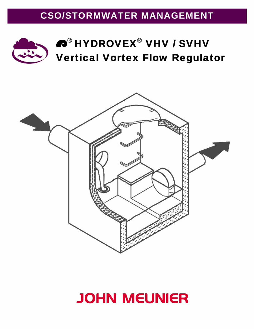
CSO/STORMWATER MANAGEMENT
® HYDROVEX® VHV / SVHV Vertical Vortex Flow Regulator
HYDROVEX® VHV / SVHV VERTICAL VORTEX FLOW REGULATOR
INTRODUCTION
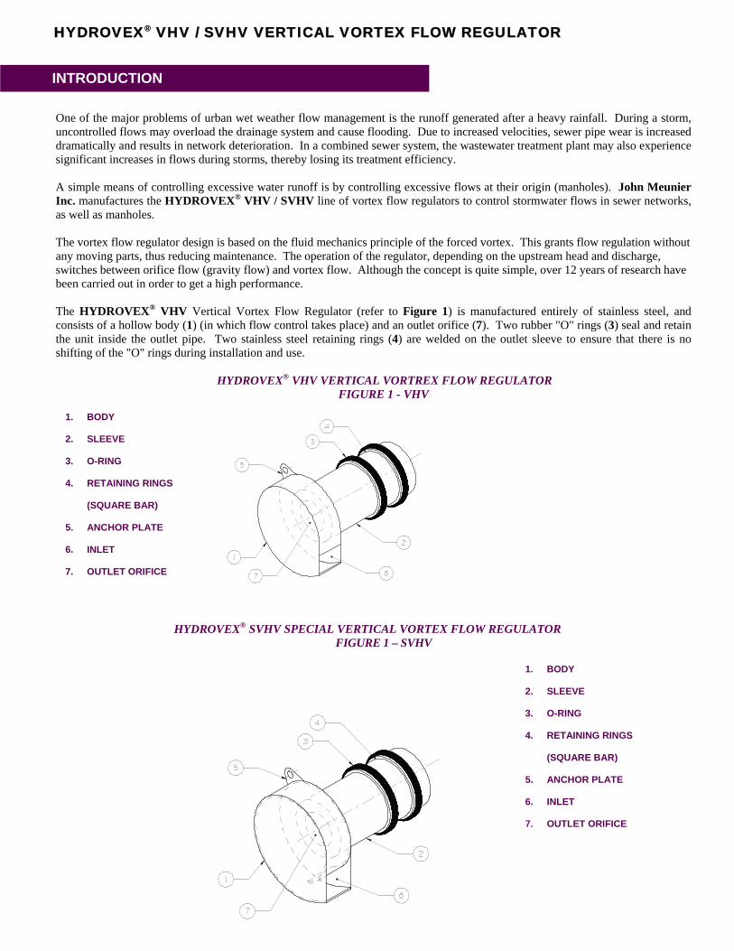
One of the major problems of urban wet weather flow management is the runoff generated after a heavy rainfall. During a storm, uncontrolled flows may overload the drainage system and cause flooding. Due to increased velocities, sewer pipe wear is increased dramatically and results in network deterioration. In a combined sewer system, the wastewater treatment plant may also experience significant increases in flows during storms, thereby losing its treatment efficiency. A simple means of controlling excessive water runoff is by controlling excessive flows at their origin (manholes). John Meunier Inc. manufactures the HYDROVEX® VHV / SVHV line of vortex flow regulators to control stormwater flows in sewer networks, as well as manholes. The vortex flow regulator design is based on the fluid mechanics principle of the forced vortex. This grants flow regulation without any moving parts, thus reducing maintenance. The operation of the regulator, depending on the upstream head and discharge, switches between orifice flow (gravity flow) and vortex flow. Although the concept is quite simple, over 12 years of research have been carried out in order to get a high performance. The HYDROVEX® VHV Vertical Vortex Flow Regulator (refer to Figure 1) is manufactured entirely of stainless steel, and consists of a hollow body (1) (in which flow control takes place) and an outlet orifice (7). Two rubber "O" rings (3) seal and retain the unit inside the outlet pipe. Two stainless steel retaining rings (4) are welded on the outlet sleeve to ensure that there is no shifting of the "O" rings during installation and use.
HYDROVEX® VHV VERTICAL VORTREX FLOW REGULATOR FIGURE 1 - VHV
1. BODY
2. SLEEVE
3. O-RING
4. RETAINING RINGS
(SQUARE BAR)
5. ANCHOR PLATE
6. INLET
7. OUTLET ORIFICE
HYDROVEX® SVHV SPECIAL VERTICAL VORTEX FLOW REGULATOR FIGURE 1 – SVHV
1. BODY
2. SLEEVE
3. O-RING
4. RETAINING RINGS
(SQUARE BAR)
7. OUTLET ORIFICE
6. INLET
5. ANCHOR PLATE
ADVANTAGES OF THE HYDROVEX® FLOW REGULATORS
• The HYDROVEX® VHV / SVHV line of flow regulators is manufactured entirely of stainless steel, making them durable and corrosion resistant.
• Having no moving parts, they require minimal maintenance. • The geometry of the HYDROVEX® VHV / SVHV flow regulators allows a control equal to an orifice
plate, having a cross section area 4 to 6 times smaller. This decreases the chance of blockage of the regulator, due to sediments and debris found in stormwater flows.
• Installation of the HYDROVEX® VHV / SVHV flow regulators is quick and straightforward and is
performed after all civil works are completed. • Installation requires no special tools or equipment and may be carried out by any contractor. • Installation may be carried out in existing structures.
HYDROVEX SELECTION CRITERIA VHV OR SVHV
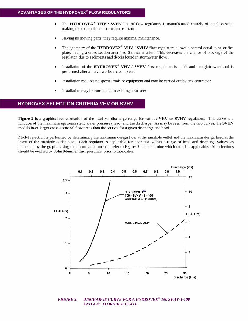
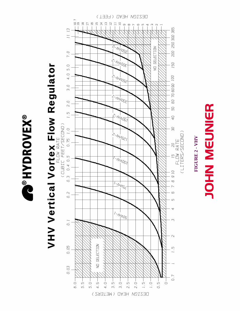
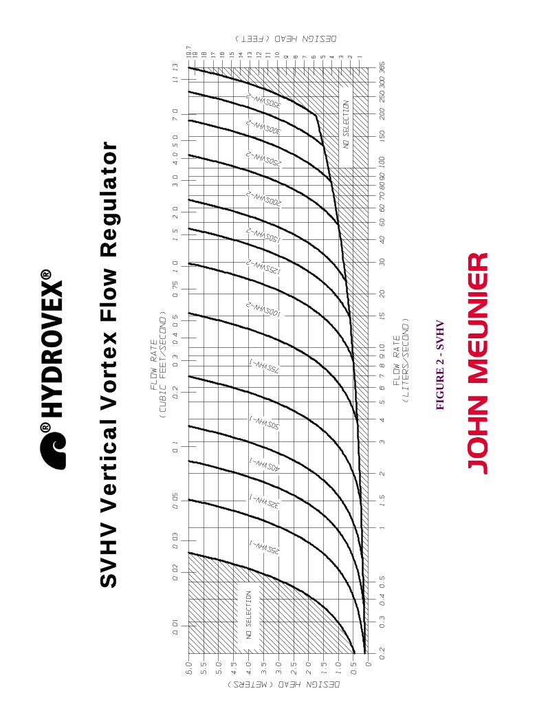
Figure 2 is a graphical representation of the head vs. discharge range for various VHV or SVHV regulators. This curve is a function of the maximum upstream static water pressure (head) and the discharge. As may be seen from the two curves, the SVHV models have larger cross-sectional flow areas than the VHV's for a given discharge and head. Model selection is performed by determining the maximum design flow at the manhole outlet and the maximum design head at the insert of the manhole outlet pipe. Each regulator is applicable for operation within a range of head and discharge values, as illustrated by the graph. Using this information one can refer to Figure 2 and determine which model is applicable. All selections should be verified by John Meunier Inc. personnel prior to fabrication
FIGURE 3: DISCHARGE CURVE FOR A HYDROVEX® 100 SVHV-1-100 AND A 4" Ø ORIFICE PLATE
VH
V V
erti
cal V
orte
x Fl
ow R
egul
ator
FIG
UR
E 2
- V
HV
FIG
UR
E 2
- SV
HV
SV
HV
Ver
tica
l Vor
tex
Flow
Reg
ulat
or
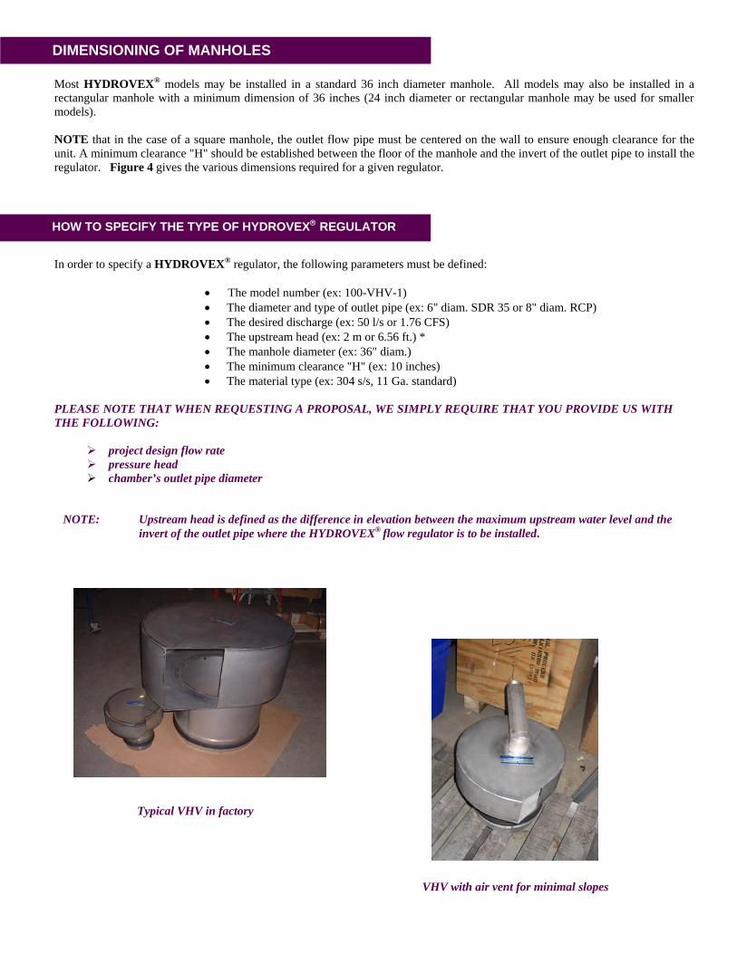
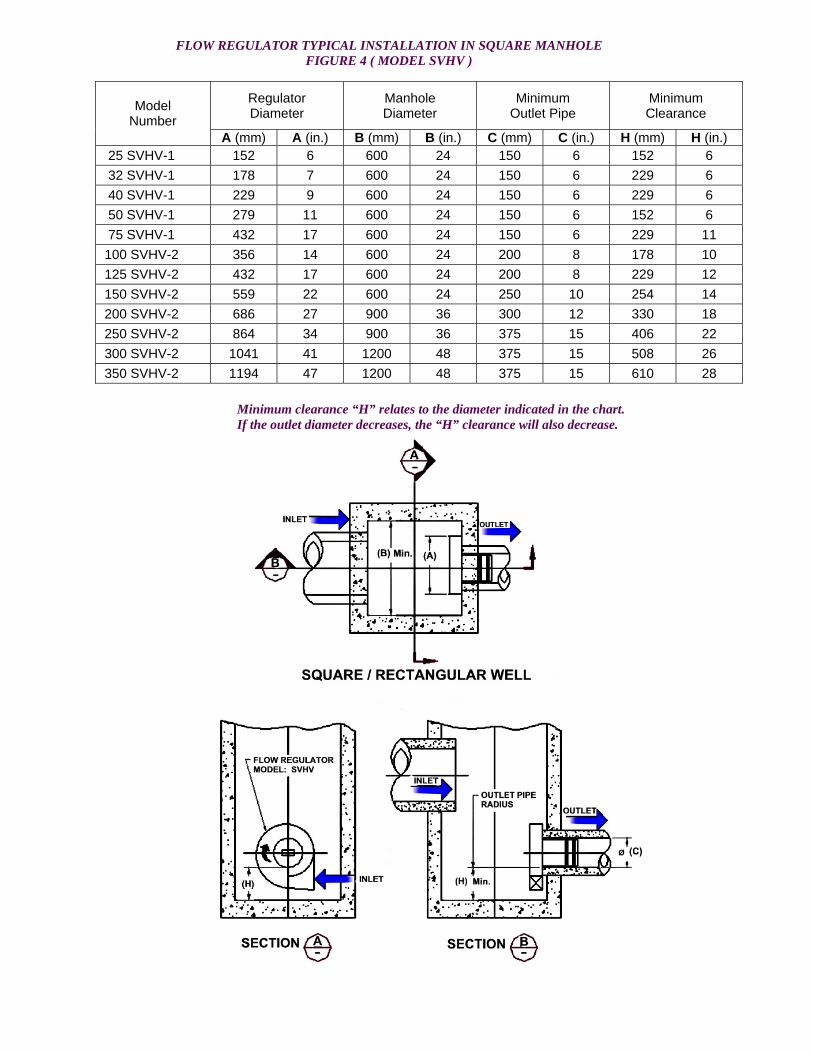
Most HYDROVEX® models may be installed in a standard 36 inch diameter manhole. All models may also be installed in a rectangular manhole with a minimum dimension of 36 inches (24 inch diameter or rectangular manhole may be used for smaller models). NOTE that in the case of a square manhole, the outlet flow pipe must be centered on the wall to ensure enough clearance for the unit. A minimum clearance "H" should be established between the floor of the manhole and the invert of the outlet pipe to install the regulator. Figure 4 gives the various dimensions required for a given regulator.
DIMENSIONING OF MANHOLES
HOW TO SPECIFY THE TYPE OF HYDROVEX® REGULATOR
In order to specify a HYDROVEX® regulator, the following parameters must be defined:
• The model number (ex: 100-VHV-1) • The diameter and type of outlet pipe (ex: 6" diam. SDR 35 or 8" diam. RCP) • The desired discharge (ex: 50 l/s or 1.76 CFS) • The upstream head (ex: 2 m or 6.56 ft.) * • The manhole diameter (ex: 36" diam.) • The minimum clearance "H" (ex: 10 inches) • The material type (ex: 304 s/s, 11 Ga. standard)
PLEASE NOTE THAT WHEN REQUESTING A PROPOSAL, WE SIMPLY REQUIRE THAT YOU PROVIDE US WITH THE FOLLOWING:
project design flow rate pressure head chamber’s outlet pipe diameter
NOTE: Upstream head is defined as the difference in elevation between the maximum upstream water level and the invert of the outlet pipe where the HYDROVEX® flow regulator is to be installed.
Typical VHV in factory
VHV with air vent for minimal slopes
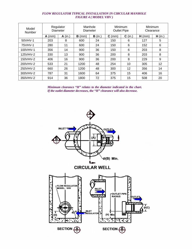
Regulator Diameter
Manhole Diameter
Minimum Outlet Pipe
Minimum Clearance Model
Number A (mm) A (in.) B (mm) B (in.) C (mm) C (in.) H (mm) H (in.)
50VHV-1 203 8 600 24 150 6 127 5 75VHV-1 280 11 600 24 150 6 152 6 100VHV-1 356 14 900 36 150 6 203 8 125VHV-2 330 13 900 36 200 8 203 8 150VHV-2 406 16 900 36 200 8 229 9 200VHV-2 533 21 1200 48 254 10 305 12 250VHV-2 660 26 1200 48 300 12 356 14 300VHV-2 787 31 1600 64 375 15 406 16 350VHV-2 914 36 1800 72 375 15 508 20
FLOW REGULATOR TYPICAL INSTALLATION IN CIRCULAR MANHOLE FIGURE 4 ( MODEL VHV )
Minimum clearance “H” relates to the diameter indicated in the chart. If the outlet diameter decreases, the “H” clearance will also decrease.
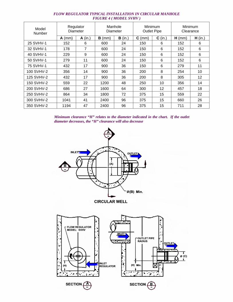
FLOW REGULATOR TYPICAL INSTALLATION IN CIRCULAR MANHOLE
FIGURE 4 ( MODEL SVHV ) Regulator
Diameter Manhole Diameter
Minimum Outlet Pipe
Minimum Clearance Model
Number A (mm) A (in.) B (mm) B (in.) C (mm) C (in.) H (mm) H (in.)
25 SVHV-1 152 6 600 24 150 6 152 6 32 SVHV-1 178 7 600 24 150 6 152 6
40 SVHV-1 229 9 600 24 150 6 152 6 50 SVHV-1 279 11 600 24 150 6 152 6 75 SVHV-1 432 17 900 36 150 6 279 11 100 SVHV-2 356 14 900 36 200 8 254 10 125 SVHV-2 432 17 900 36 200 8 305 12
150 SVHV-2 559 22 1200 48 250 10 356 14 200 SVHV-2 686 27 1600 64 300 12 457 18 250 SVHV-2 864 34 1800 72 375 15 559 22 300 SVHV-2 1041 41 2400 96 375 15 660 26 350 SVHV-2 1194 47 2400 96 375 15 711 28 Minimum clearance “H” relates to the diameter indicated in the chart. If the outlet
diameter decreases, the “H” clearance will also decrease

FLOW REGULATOR TYPICAL INSTALLATION IN SQUARE MANHOLE FIGURE 4 ( MODEL VHV )
Regulator Diameter
Manhole Diameter
Minimum Outlet Pipe
Minimum Clearance Model
Number A (mm) A (in.) B (mm) B (in.) C (mm) C (in.) H (mm) H (in.)
50VHV-1 203 8 600 24 150 6 127 5 75VHV-1 280 11 600 24 150 6 152 6
100VHV-1 356 14 600 24 150 6 203 8 125VHV-2 330 13 600 24 200 8 203 8 150VHV-2 406 16 600 24 200 8 229 9 200VHV-2 533 21 900 36 254 10 305 12 250VHV-2 660 26 900 36 300 12 356 14 300VHV-2 787 31 1200 48 375 15 406 16 350VHV-2 914 36 1200 48 375 15 508 20
Minimum clearance “H” relates to the diameter indicated in the chart. If the outlet diameter decreases, the “H” clearance will also decrease.
Regulator Diameter
Manhole Diameter
Minimum Outlet Pipe
Minimum Clearance Model
Number A (mm) A (in.) B (mm) B (in.) C (mm) C (in.) H (mm) H (in.)
25 SVHV-1 152 6 600 24 150 6 152 6 32 SVHV-1 178 7 600 24 150 6 229 6 40 SVHV-1 229 9 600 24 150 6 229 6 50 SVHV-1 279 11 600 24 150 6 152 6 75 SVHV-1 432 17 600 24 150 6 229 11 100 SVHV-2 356 14 600 24 200 8 178 10 125 SVHV-2 432 17 600 24 200 8 229 12 150 SVHV-2 559 22 600 24 250 10 254 14 200 SVHV-2 686 27 900 36 300 12 330 18 250 SVHV-2 864 34 900 36 375 15 406 22 300 SVHV-2 1041 41 1200 48 375 15 508 26 350 SVHV-2 1194 47 1200 48 375 15 610 28
FLOW REGULATOR TYPICAL INSTALLATION IN SQUARE MANHOLE FIGURE 4 ( MODEL SVHV )
Minimum clearance “H” relates to the diameter indicated in the chart. If the outlet diameter decreases, the “H” clearance will also decrease.
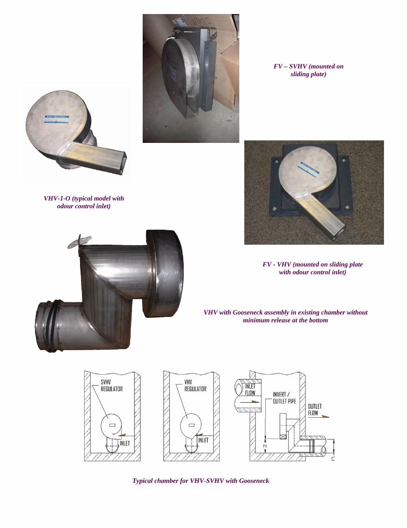
Typical chamber for VHV-SVHV with Gooseneck
FV – SVHV (mounted on sliding plate)
FV - VHV (mounted on sliding plate with odour control inlet)
VHV with Gooseneck assembly in existing chamber without minimum release at the bottom
VHV-1-O (typical model with odour control inlet)
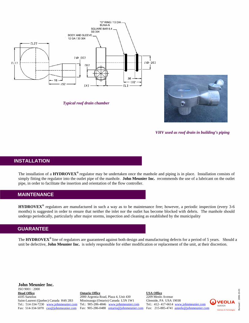
Typical roof drain chamber VHV used as roof drain in building’s piping
INSTALLATION
The installation of a HYDROVEX® regulator may be undertaken once the manhole and piping is in place. Installation consists of simply fitting the regulator into the outlet pipe of the manhole. John Meunier Inc. recommends the use of a lubricant on the outlet pipe, in order to facilitate the insertion and orientation of the flow controller.
MAINTENANCE
HYDROVEX® regulators are manufactured in such a way as to be maintenance free; however, a periodic inspection (every 3-6 months) is suggested in order to ensure that neither the inlet nor the outlet has become blocked with debris. The manhole should undergo periodically, particularly after major storms, inspection and cleaning as established by the municipality
GUARANTEE
The HYDROVEX® line of regulators are guaranteed against both design and manufacturing defects for a period of 5 years. Should a unit be defective, John Meunier Inc. is solely responsible for either modification or replacement of the unit, at their discretion.
John Meunier Inc. ISO 9001 : 2000
Rev
ised
: 2
008-
10-0
1
Head Office 4105 Sartelon Saint-Laurent (Quebec) Canada H4S 2B3 Tel.: 514-334-7230 www.johnmeunier.com Fax: 514-334-5070 [email protected]
Ontario Office 2000 Argentia Road, Plaza 4, Unit 430 Mississauga (Ontario) Canada L5N 1W1 Tel.: 905-286-4846 www.johnmeunier.com
USA Office 2209 Menlo Avenue Glenside, PA USA 19038 Tel.: 412- 417-6614 www.johnmeunier.com Fax: 215-885-4741 [email protected] Fax: 905-286-0488 [email protected]


![OVAL VORTEX FLOWMETER / THERMISTOR TYPE VORTEX … · 2019. 1. 10. · 3 OVAL VORTEX FLOWMETER GBD110E-6 FLOW RANGES The OVAL VORTEX FLOWMETER measures actual flow rate (m3/h[actual])](https://img.pdfslide.net/doc/110x75/5fec29af0bfeaf2fc470a314/oval-vortex-flowmeter-thermistor-type-vortex-2019-1-10-3-oval-vortex-flowmeter.jpg)