Embed Size (px)
Citation preview

ENGINEERING FOR SUSTAINABLE GROWTH
HY.GENON-SITE HYDROGENGENERATION SYSTEMCOST-EFFECTIVE STEAM METHANE REFORMING
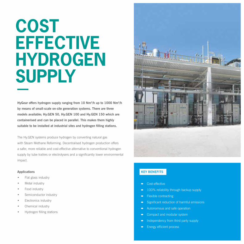
HyGear offers hydrogen supply ranging from 10 Nm3/h up to 1000 Nm3/h
by means of small-scale on-site generation systems. There are three
models available; Hy.GEN 50, Hy.GEN 100 and Hy.GEN 150 which are
containerised and can be placed in parallel. This makes them highly
suitable to be installed at industrial sites and hydrogen filling stations.
The Hy.GEN systems produce hydrogen by converting natural gas
with Steam Methane Reforming. Decentralised hydrogen production offers
a safer, more reliable and cost-effective alternative to conventional hydrogen
supply by tube trailers or electrolysers and a significantly lower environmental
impact.
Applications
• Flat glass industry
• Metal industry
• Food industry
• Semiconductor industry
• Electronics industry
• Chemical industry
• Hydrogen filling stations
COST EFFECTIVE HYDROGEN SUPPLY
KEY BENEFITS
Cost-effective
100% reliability through backup supply
Flexible contracting
Significant reduction of harmful emissions
Autonomous and safe operation
Compact and modular system
Independency from third party supply
Energy efficient process

TECHNOLOGY
Advanced reforming
HyGear uses its proprietary reforming technology to generate a hydrogen
rich stream from natural gas. To ensure long lifetime, high system efficiency
and avoid catalyst deactivation, the natural gas is stripped from sulphur
before it is led into the reformer.
Effective (V)PSA technology
HyGear uses Vacuum Pressure Swing Adsorption technology. This is
more energy and cost efficient than traditional gas separation systems.
The (V)PSA consists of four parallel active vessels, enabling a continuous
cleaning process. In the (V)PSA, the hydrogen is separated from other
gaseous species under elevated pressure by using differences in adsorption
properties.
Optimised energy efficiency
By re-using the waste gases and waste heat of the process, the energy
efficiency of the Hy.GEN is optimised to the highest level. No external fuel
gases are needed for the reform reaction and steam generation.
The off-gas from the (V)PSA is used as input for the burner that provides
heat for the reforming reaction. The residual heat is used for generating
steam, which is mixed with natural gas for the steam reforming process.
Connectivity
The system includes gas desulphurisation and water purification and can
therefore be connected directly to the natural gas and feed water lines. Other
required connections are electricity for controls and auxiliaries, hydrogen and
nitrogen for system start-up and compressed air for valve operation.
The steam (H2O) produced from waste heat is added to
the desulphurised gas and led into the reformer. The heat
and catalytic properties of the reformer cause the following
reaction: CH4 + H2O 3H2 + CO.
The remaining carbon monoxide is then converted in the
Water Gas Shift assembly (WGS) to produce more hydrogen:
CO + H2O CO2 + H2.
The gases then enter the PSA where the hydrogen is
separated from other gaseous species under elevated pressure
using differences in adsorption properties.
The cleaned hydrogen is then stored in the buffer vessel
and can be used as an industrial gas or energy source.
NATURAL GAS
DESULPHURISATIONSYSTEM
STEAM
WATER
PSA
H2O CO H2
HYDROGENBUFFER
CO2CH4
CO2BURNER
REFORMER
OFF GAS STORAGE
WGS

1. Ventilation fan
2. Desulphurisation vessel
3. PSA-vessels
4. Off-gas storage
5. Hydrogen storage
6. Water separator for vacuum pump
7. Vacuum pump
8. Coolant heater
9. Reformate cooler
10. Electronics cabinet
11. Steam generator
12. Reformer unit
13. Low temperature shift
14. Coolant expansion vessel
15. Burner air blower
16. Water purification system
WHAT’S INSIDE
8
9
10
11
12
13
14
15
16
1
3
6
5
4
7
2

SPECIFICATIONS
IF YOU REQUIRE OTHER SPECIFICATIONS, CONTACT US TO ASSIST YOU WITH THE MOST OPTIMAL SOLUTION.
MODEL Hy.GEN 50 Hy.GEN 100 Hy.GEN 150
OUTPUT
Nominal hydrogen flow*Dependent on hydrogen purity
Max. 47 Nm3/h Max. 94 Nm3/h Max. 141 Nm3/h
Hydrogen purity range 99.5% - 99.9999% 99.5% - 99.9999% 99.5% - 99.9999%
Pressure range 1.5 - 7.0 bar(g) 1.5 - 7.0 bar(g) 1.5 - 7.0 bar(g)
TYPICAL CONSUMPTION DATA
Natural gas Max. 23 Nm3/h Max. 46 Nm3/h Max. 69 Nm3/h
Electricity 14.5 kWe 26.0 kWe 29.5 kWe
Water 100 L/h 200 L/h 300 L/h
Compressed air Max. 1.5 Nm3/h Max. 3.0 Nm3/h Max. 4.5 Nm3/h
DIMENSIONS
Size 20 ft 40 ft 40 ft
Weight 7,300 kg 12,000 kg 15,000 kg
OPERATING CONDITIONS
Start up time (warm) Max. 30 min Max. 30 min Max. 30 min
Start up time (cold) Max. 3 h Max. 3 h Max. 3 h
Modulation (H2 product flow) 0 - 100 % 0 - 100 % 0 - 100 %
Modulation reformer (output) 10 - 100 % 10 - 100 % 10 - 100 %
Ambient temperature range -20 °C to +40 °C -20 °C to +40 °C -20 °C to +40 °C
All data and values are indicative and based on nominal and non-frost conditions.
Values might differ due to local circumstances and feedstock characteristics.
Normal condition (Nm3) is defined at a temperature of 0OC and pressure of 1.013 bar(a).

FIND US
www.hygear.com
HEADOFFICENETHERLANDS
FIND US
Westervoortsedijk 73
6827 AV Arnhem
SEND US
P.O. Box 5280
6802 EG Arnhem
CONTACT US
T +31 88 9494 300
W www.hygear.com
SALES
T +31 88 9494 308
USA
T +31 88 9494 304
Europe
T +31 88 9494 300
Asia
T +65 6909 3064
HyGear Asia Pte. Ltd.
133 Cecil Street
#09-01B Keck Seng Tower
Singapore 069535