Embed Size (px)
Citation preview
E-M-HF4-V1_14 Rotronic AG Bassersdorf, Switzerland
Document code Unit
Instruction Manual
Document Type
HygroFlex HF4 Humidity Temperature Transmitters: User Guide
Document title Page 1 of 34
© 2008; Rotronic AG E-M-HF4-V1_14
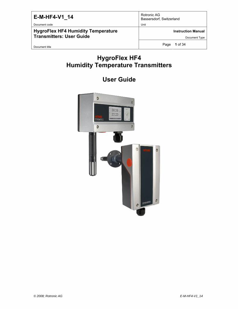
HygroFlex HF4 Humidity Temperature Transmitters
User Guide
E-M-HF4-V1_14 Rotronic AG Bassersdorf, Switzerland
Document code Unit
Instruction Manual
Document Type
HygroFlex HF4 Humidity Temperature Transmitters: User Guide
Document title Page 2 of 34
© 2008; Rotronic AG E-M-HF4-V1_14
Table of contents
1 Overview ..............................................................................................................................................3 2 Models..................................................................................................................................................4 2.1 Ordering codes .................................................................................................................................4 2.2 Mechanical configurations and dimensions ......................................................................................7 2.3 Display and keypad option ...............................................................................................................8 3 General description.............................................................................................................................8 3.1 Power supply ....................................................................................................................................8 3.2 Measured parameters ......................................................................................................................8 3.3 Calculated parameters .....................................................................................................................9 3.4 Analog output signals (HF42 and HF43) ..........................................................................................9 3.5 Digital interface (HF45)...................................................................................................................10 3.6 Service connector...........................................................................................................................11 3.7 Sensor protection (dust filter)..........................................................................................................11 4 User configurable settings and functions.......................................................................................11 4.1 Function overview...........................................................................................................................12 4.2 Factory default settings ..................................................................................................................13 5 Mechanical installation .....................................................................................................................15 5.1 General guidelines..........................................................................................................................15 5.2 HF4 enclosure ................................................................................................................................15 5.3 Installation of the HF4 type D (through wall mount)........................................................................15 5.4 Installation of the HF4 type W (surface mount)...............................................................................16 6 Electrical installation ........................................................................................................................17 6.1 General wiring guidelines ...............................................................................................................17 6.2 Guidelines for RS-485 wiring (HF45)..............................................................................................18 6.3 Cable grip and cable specifications ................................................................................................18 6.4 Wiring .............................................................................................................................................18 7 Operation ...........................................................................................................................................22 7.1 Minimum load requirements for the HF43 with voltage outputs ......................................................22 7.2 HF42 and HF43 transmitters (analog outputs)................................................................................22 7.3 HF45 (digital output) .......................................................................................................................23 7.4 Internal menu (optional keypad and display) ..................................................................................24 7.5 Displayed parameters (optional keypad and display) .....................................................................24 8 Maintenance ......................................................................................................................................25 8.1 Service cable ..................................................................................................................................25 8.2 Location of the service connector (mini USB type) .........................................................................25 8.3 Periodic calibration check...............................................................................................................25 8.4 Cleaning or replacing the dust filter ................................................................................................26 8.5 Validation of the output signals transmission..................................................................................26 9 Firmware updates..............................................................................................................................26 10 Technical data ...................................................................................................................................27 10.1 Specifications .................................................................................................................................27 10.2 Dew point accuracy ........................................................................................................................29 11 Accessories .......................................................................................................................................30 11.1 Configuration and communication software....................................................................................30 11.2 Service cables ................................................................................................................................30 11.3 USB / RS-485 converter cable........................................................................................................31 11.4 Mounting hardware.........................................................................................................................31 11.5 Calibration accessories ..................................................................................................................32 11.6 Spare filters ....................................................................................................................................32 12 Supporting documents .....................................................................................................................33 13 Document releases ...........................................................................................................................34
E-M-HF4-V1_14 Rotronic AG Bassersdorf, Switzerland
Document code Unit
Instruction Manual
Document Type
HygroFlex HF4 Humidity Temperature Transmitters: User Guide
Document title Page 3 of 34
© 2008; Rotronic AG E-M-HF4-V1_14
Applicability: This manual applies to all instruments of the HF4 series with firmware version 1.x, where 1.x can be 1.0, 1.1, etc. Changes to the last digit of the version number reflect minor firmware changes that do not affect the manner in which the instrument should be operated.
1 Overview The HF4 transmitter measures temperature, relative humidity and the dew or frost point. The HF4 series is designed for fixed installation in HVAC and light industrial applications where a high measurement accuracy is required at conditions within the range of 0 to 100 %RH and -50 to 100C (-58 to 212F). The electronics operating range is limited to -40…60 °C (-10…60°C with the optional LC display). The HF4 features well proven sensors and a robust housing. Digital signal processing ensures consistent product performance and also facilitates the task of field maintenance with features such as potentiometer free – digital calibration. Based on the ROTRONIC AirChip 3000 digital technology the HF4 series offers the following functions: User configurable settings Calculation of the dew or frost point Humidity temperature calibration and adjustment Simulator mode Automatic humidity sensor test and drift compensation Fail safe mode Data recording The ability for the user to easily update the AirChip 3000 firmware means that instruments of the HF4 series can be kept up-to-date regarding any future functionality improvement. HF4 transmitters with analog output signals: two types of electronic circuit are available: HF42: 2-wire, loop powered (4…20 mA current signal) and HF43: 3-wire (voltage or current signal). Both circuit types provide linear analog outputs signals for transmission over a length of cable to a remote display, recorder, controller or data processing unit and can be used to measure humidity only, temperature only or both parameters. HF4 transmitters with digital output: the HF45 is available with the following digital interface options: RS-485, USB + RS-485 or Ethernet (TCP/IP) + RS-485. Use of a digital interface allows the simultaneous reading of relative humidity, temperature and calculated parameter. The communication protocol used by the RS-485 interface offers several options that can be configured by the user. This includes a Modbus compatible protocol.
E-M-HF4-V1_14 Rotronic AG Bassersdorf, Switzerland
Document code Unit
Instruction Manual
Document Type
HygroFlex HF4 Humidity Temperature Transmitters: User Guide
Document title Page 4 of 34
© 2008; Rotronic AG E-M-HF4-V1_14
2 Models
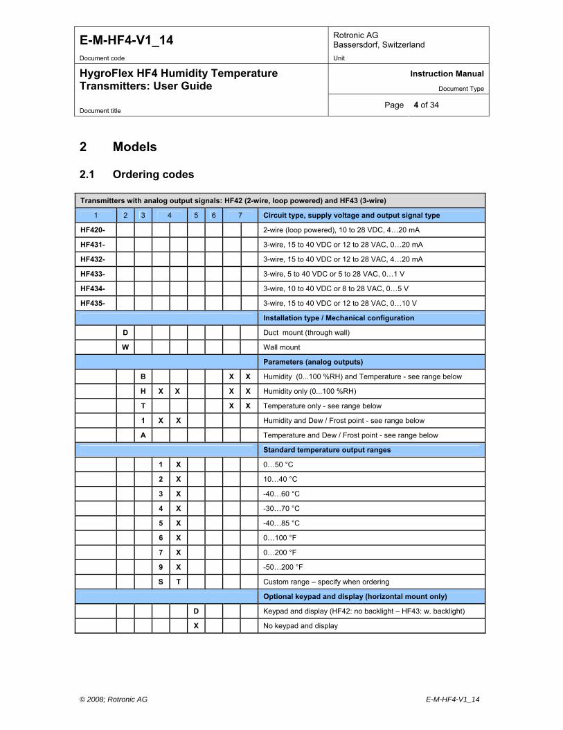
2.1 Ordering codes
Transmitters with analog output signals: HF42 (2-wire, loop powered) and HF43 (3-wire)
1 2 3 4 5 6 7 Circuit type, supply voltage and output signal type
HF420- 2-wire (loop powered), 10 to 28 VDC, 4…20 mA
HF431- 3-wire, 15 to 40 VDC or 12 to 28 VAC, 0…20 mA
HF432- 3-wire, 15 to 40 VDC or 12 to 28 VAC, 4…20 mA
HF433- 3-wire, 5 to 40 VDC or 5 to 28 VAC, 0…1 V
HF434- 3-wire, 10 to 40 VDC or 8 to 28 VAC, 0…5 V
HF435- 3-wire, 15 to 40 VDC or 12 to 28 VAC, 0…10 V
Installation type / Mechanical configuration
D Duct mount (through wall)
W Wall mount
Parameters (analog outputs)
B X X Humidity (0...100 %RH) and Temperature - see range below
H X X X X Humidity only (0...100 %RH)
T X X Temperature only - see range below
1 X X Humidity and Dew / Frost point - see range below
A Temperature and Dew / Frost point - see range below
Standard temperature output ranges
1 X 0…50 °C
2 X 10…40 °C
3 X -40…60 °C
4 X -30…70 °C
5 X -40…85 °C
6 X 0…100 °F
7 X 0…200 °F
9 X -50…200 °F
S T Custom range – specify when ordering
Optional keypad and display (horizontal mount only)
D Keypad and display (HF42: no backlight – HF43: w. backlight)
X No keypad and display
E-M-HF4-V1_14 Rotronic AG Bassersdorf, Switzerland
Document code Unit
Instruction Manual
Document Type
HygroFlex HF4 Humidity Temperature Transmitters: User Guide
Document title Page 5 of 34
© 2008; Rotronic AG E-M-HF4-V1_14
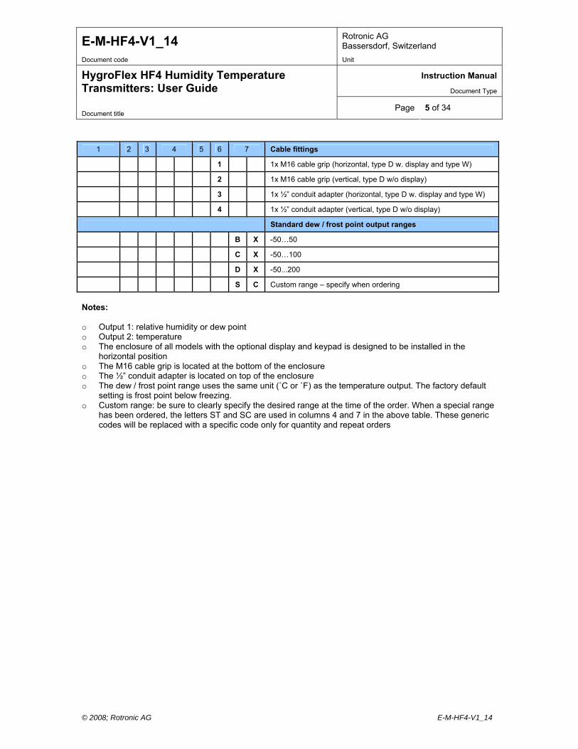
1 2 3 4 5 6 7 Cable fittings
1 1x M16 cable grip (horizontal, type D w. display and type W)
2 1x M16 cable grip (vertical, type D w/o display)
3 1x ½” conduit adapter (horizontal, type D w. display and type W)
4 1x ½” conduit adapter (vertical, type D w/o display)
Standard dew / frost point output ranges
B X -50…50
C X -50…100
D X -50...200
S C Custom range – specify when ordering
Notes: o Output 1: relative humidity or dew point o Output 2: temperature o The enclosure of all models with the optional display and keypad is designed to be installed in the
horizontal position o The M16 cable grip is located at the bottom of the enclosure o The ½” conduit adapter is located on top of the enclosure o The dew / frost point range uses the same unit (˚C or ˚F) as the temperature output. The factory default
setting is frost point below freezing. o Custom range: be sure to clearly specify the desired range at the time of the order. When a special range
has been ordered, the letters ST and SC are used in columns 4 and 7 in the above table. These generic codes will be replaced with a specific code only for quantity and repeat orders
E-M-HF4-V1_14 Rotronic AG Bassersdorf, Switzerland
Document code Unit
Instruction Manual
Document Type
HygroFlex HF4 Humidity Temperature Transmitters: User Guide
Document title Page 6 of 34
© 2008; Rotronic AG E-M-HF4-V1_14
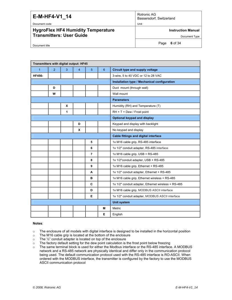
Transmitters with digital output: HF45
1 2 3 4 5 6 Circuit type and supply voltage
HF456- 3-wire, 5 to 40 VDC or 12 to 28 VAC
Installation type / Mechanical configuration
D Duct mount (through wall)
W Wall mount
Parameters
X Humidity (RH) and Temperature (T)
1 RH + T + Dew / Frost point
Optional keypad and display
D Keypad and display with backlight
X No keypad and display
Cable fittings and digital interface
5 1x M16 cable grip, RS-485 interface
6 1x 1/2" conduit adapter, RS-485 interface
7 1x M16 cable grip, USB + RS-485
8 1x 1/2"conduit adapter, USB + RS-485
9 1x M16 cable grip, Ethernet + RS-485
A 1x 1/2" conduit adapter, Ethernet + RS-485
B 1x M16 cable grip, Ethernet wireless + RS-485
C 1x 1/2" conduit adapter, Ethernet wireless + RS-485
D 1x M16 cable grip, MODBUS ASCII interface
E 1x 1/2" conduit adapter, MODBUS ASCII interface
Unit system
M Metric
E English
Notes: o The enclosure of all models with digital interface is designed to be installed in the horizontal position o The M16 cable grip is located at the bottom of the enclosure o The ½” conduit adapter is located on top of the enclosure o The factory default setting for the dew point calculation is the frost point below freezing o The same terminal block is used for either the Modbus interface or the RS-485 interface. A MODBUS
network and a RS-485 network are physically identical and differ only in the communication protocol being used. The default communication protocol used with the RS-485 interface is RO-ASCII. When ordered with the MODBUS interface, the transmitter is configured by the factory to use the MODBUS ASCII communication protocol
E-M-HF4-V1_14 Rotronic AG Bassersdorf, Switzerland
Document code Unit
Instruction Manual
Document Type
HygroFlex HF4 Humidity Temperature Transmitters: User Guide
Document title Page 7 of 34
© 2008; Rotronic AG E-M-HF4-V1_14
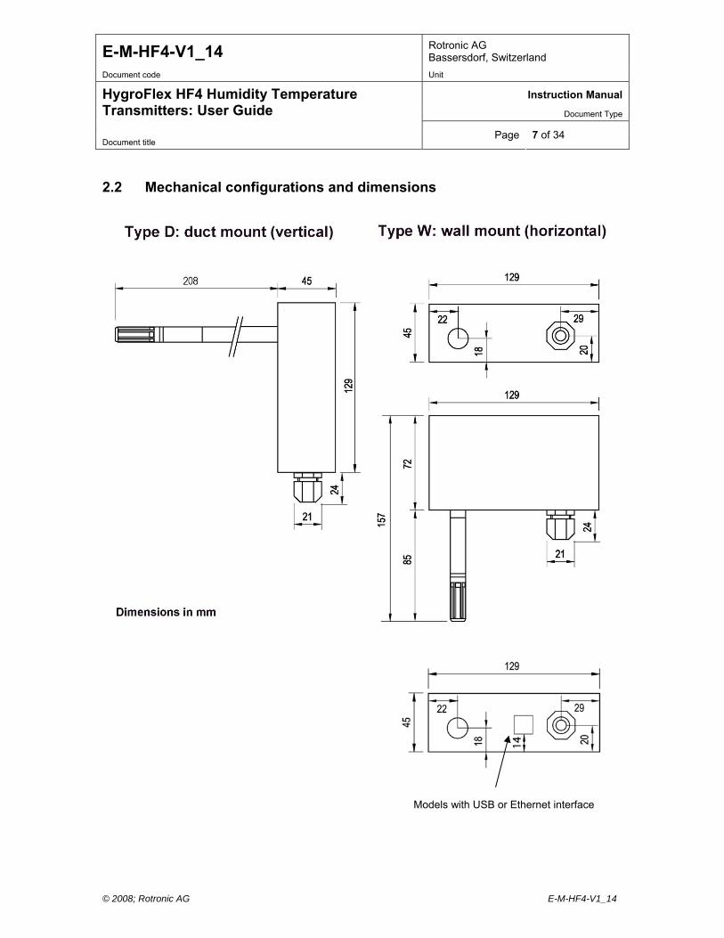
2.2 Mechanical configurations and dimensions
Models with USB or Ethernet interface

E-M-HF4-V1_14 Rotronic AG Bassersdorf, Switzerland
Document code Unit
Instruction Manual
Document Type
HygroFlex HF4 Humidity Temperature Transmitters: User Guide
Document title Page 8 of 34
© 2008; Rotronic AG E-M-HF4-V1_14
ht.
s to
2.3 Display and keypad option
The LC display option for the HF43 and HF45 has abacklight. The LC display option for the HF42 does not have a backlig
The upper line corresponds to relative humidity or dew / frost point and the bottom line correspondtemperature.
The display can be configured to show a trend indicator on each line: : increasing value : decreasing value In the event of an alarm the display shows the symbol [ ! ] to the right of the value. For instructions see the following HW4 manual: E-M-HW4v2-F2-003.
3 General description
3.1 Power supply Depending on the circuit type, the HF4 requires the following power supply: a) HF42 (2-wire, loop powered): 10…28 VDC - depending on the load connected to the output(s). The
minimum supply voltage can be determined as follows: V min = 10 V + (0.02 x Load*) *Load resistance in ohms. For the maximum load of 500 , the minimum supply voltage is 10 + (0.02 x 500) = 20 VDC. With both output circuits closed, the maximum current consumption is 40 mA.
b) HF43 (3-wire with analog outputs): 15 to 40 VDC (see note below) or 12 to 28 VAC. With both output circuits closed, the maximum current consumption is 50 mA. Note: depending on the type of output signal, the HF43 will operate with the following minimum voltage 0…1 V outputs: 5 VDC or 5 VAC 0…5 V outputs: 10 VDC or 8 VAC 0…10 V outputs: 15 VDC or 12 VAC 0…20 mA or 4 …20 mA outputs: 6 VDC or 5 VAC with 0 load 15 VDC or 12 VAC with 500 load
c) HF45 (3-wire) with digital outputs: 5 to 40 VDC or 12 to 28 VAC. Maximum current consumption: Model with USB interface: 50 mA Model with Ethernet (TCP/IP) interface: 300 mA
3.2 Measured parameters The HF4 measures relative humidity with a ROTRONIC Hygromer® IN1 capacitive sensor and temperature with a Pt100 RTD.
E-M-HF4-V1_14 Rotronic AG Bassersdorf, Switzerland
Document code Unit
Instruction Manual
Document Type
HygroFlex HF4 Humidity Temperature Transmitters: User Guide
Document title Page 9 of 34
© 2008; Rotronic AG E-M-HF4-V1_14
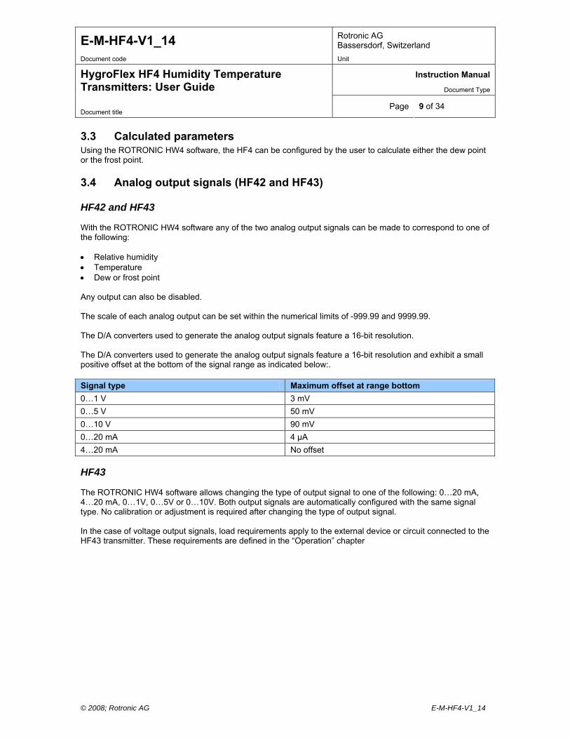
3.3 Calculated parameters Using the ROTRONIC HW4 software, the HF4 can be configured by the user to calculate either the dew point or the frost point.
3.4 Analog output signals (HF42 and HF43) HF42 and HF43 With the ROTRONIC HW4 software any of the two analog output signals can be made to correspond to one of the following: Relative humidity Temperature Dew or frost point Any output can also be disabled. The scale of each analog output can be set within the numerical limits of -999.99 and 9999.99. The D/A converters used to generate the analog output signals feature a 16-bit resolution. The D/A converters used to generate the analog output signals feature a 16-bit resolution and exhibit a small positive offset at the bottom of the signal range as indicated below:. Signal type Maximum offset at range bottom
0…1 V 3 mV
0…5 V 50 mV
0…10 V 90 mV
0…20 mA 4 µA
4…20 mA No offset HF43 The ROTRONIC HW4 software allows changing the type of output signal to one of the following: 0…20 mA, 4…20 mA, 0…1V, 0…5V or 0…10V. Both output signals are automatically configured with the same signal type. No calibration or adjustment is required after changing the type of output signal. In the case of voltage output signals, load requirements apply to the external device or circuit connected to the HF43 transmitter. These requirements are defined in the “Operation” chapter
E-M-HF4-V1_14 Rotronic AG Bassersdorf, Switzerland
Document code Unit
Instruction Manual
Document Type
HygroFlex HF4 Humidity Temperature Transmitters: User Guide
Document title Page 10 of 34
© 2008; Rotronic AG E-M-HF4-V1_14
3.5 Digital interface (HF45) a) RS-485 serial interface The HF45 has always a RS-485 serial interface. When the number of available network ports is limited, this interface can be used to connect together up to 64 devices in a multi-dropped arrangement. In principle, an unlimited number of such networks can be monitored with the HW4 software, but each RS-485 multi-drop network is limited to 64 devices. The HF45 can be used either as a slave or a master, without special configuration. The master is automatically the device that is directly connected to a network (PC or LAN) by means of a USB port or TCP/IP port. RS-485 Compatibility: The communication protocol used by the HF45 and other AirChip 3000 products is not compatible with the protocol used by the previous generation of ROTRONIC instruments. Do not connect legacy products and AirChip 3000 products to the same RS-485 multi-drop network. b) USB or Ethernet interface The HF45 is also available with the following interface combinations: USB + RS-485 or Ethernet +RS-485. In that case the protection grade of the HF4 enclosure is no longer IP65 / NEMA 4 rated. c) Communication protocol options The measurement data can be read without having to use the ROTRONIC HW4 software. Starting with firmware version 1.3, the HF4 offers the following communication protocol options (ASCII) which can be selected by connecting the HF4 to a PC running the ROTRONIC HW4 software (version 2.1.1 or higher): o RO-ASCII: this is the standard (default) communication protocol used by all AirChip 3000 devices and by
the HW4 software. In principle, this protocol supports all of the AirChip 3000 functions but some of the functions require a certain amount of computations to be carried out by an external device such as a PC.
o Custom: this communication protocol can be used to provide compatibility of the HF4 with an existing communication system. The Custom communication protocol is limited to reading measurement data from the HF4. Functions such as device configuration, humidity and temperature adjustment, etc. are not supported. The Custom protocol is applicable to all AirChip 3000 devices with a digital interface and allows RS-485 networking
o Modbus: the Modbus protocol available with the HF4 is limited to reading measurement data from the HF4. Functions such as device configuration, humidity and temperature adjustment, etc. are not supported by the Modbus protocol.
When using either the RO-ASCII or the Custom protocol, the HF4 can be set to send data automatically after each refresh cycle without requiring a data request. When this mode is enabled, the receiving device must be listening at all times in order to get the measurement data. For details, see document E-M-AC3000-CP

E-M-HF4-V1_14 Rotronic AG Bassersdorf, Switzerland
Document code Unit
Instruction Manual
Document Type
HygroFlex HF4 Humidity Temperature Transmitters: User Guide
Document title Page 11 of 34
© 2008; Rotronic AG E-M-HF4-V1_14
3.6 Service connector The service connector (UART interface with a mini-USB type connector) allows connecting the HF4 either to a PC running the ROTRONIC HW4 software or to a probe input of another instrument that is compatible with the HygroClip 2 (HC2) probes. In both cases a service cable is required. See “Maintenance” for the location of the service connector and for the type of service cable to be used. Connecting the HF4 to a PC is used to configure the HF4, gain access to the HF4 functions such as
humidity and temperature adjustment, read data from the HF4 on the PC and update the AirChip 3000 firmware.
Connecting the HF4 to the probe input of another instrument is useful only when the other instrument has
its own display and keypad, and has an internal menu equivalent to the menu of the HP23 hand-held calibrator. The connection allows showing the data measured by the HF4 on the other instrument display and also allows using the other instrument internal menu to do for example a humidity and temperature adjustment of the HF4.
o HF45 (digital outputs): the digital interface (USB, Ethernet and RS-485) offers the same functionality as
the service connector but does not allow connecting the HF4 to a HP23 hand-held calibrator.
3.7 Sensor protection (dust filter) The HF4 is supplied with a Polyethylene filter to protect the sensors against dust particles and high air velocity.
4 User configurable settings and functions The HF4 ships configured as specified on the customer order. Models with analog outputs can be installed and used just as any conventional humidity and temperature transmitter and most users will never need to use the HF4 configurable settings and functions. Models with a digital interface generally require some configuration by the user. Making use of the HF4 configurable settings and functions is entirely up to the user and the appropriate settings depend on the user application. We have provided below a short description of the HF4 functions and also indicated the factory default settings.
E-M-HF4-V1_14 Rotronic AG Bassersdorf, Switzerland
Document code Unit
Instruction Manual
Document Type
HygroFlex HF4 Humidity Temperature Transmitters: User Guide
Document title Page 12 of 34
© 2008; Rotronic AG E-M-HF4-V1_14
4.1 Function overview
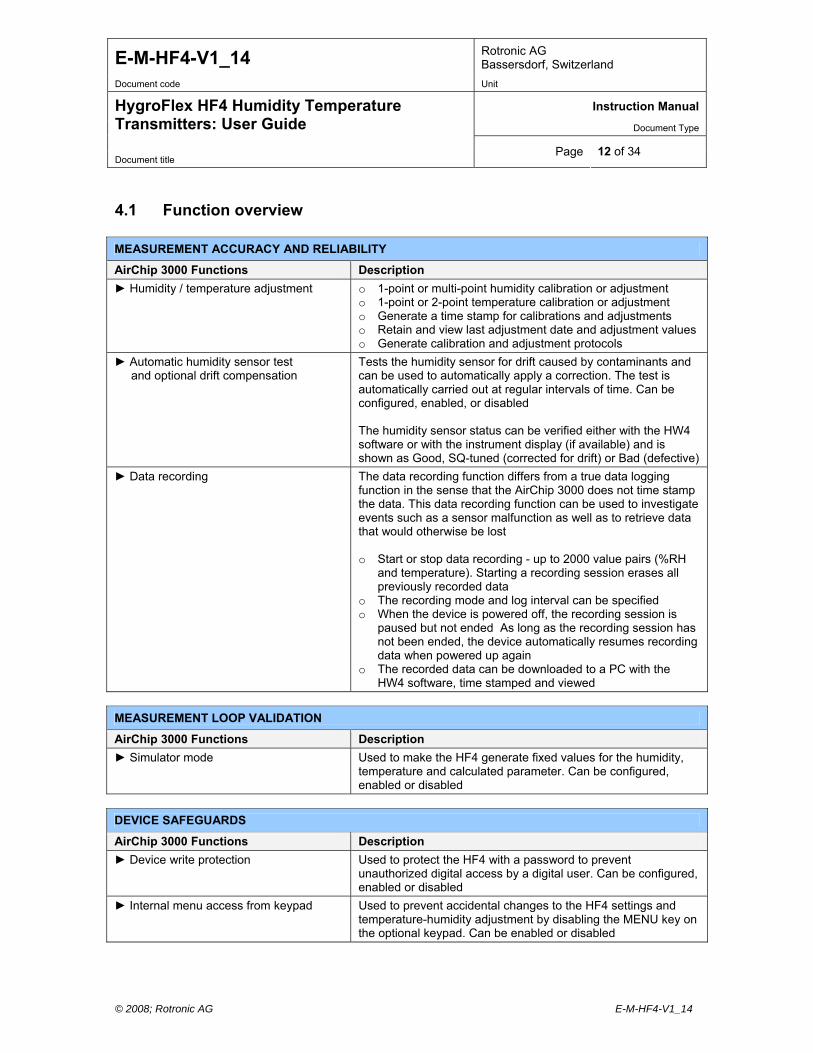
MEASUREMENT ACCURACY AND RELIABILITY
AirChip 3000 Functions Description
Humidity / temperature adjustment o 1-point or multi-point humidity calibration or adjustment o 1-point or 2-point temperature calibration or adjustment o Generate a time stamp for calibrations and adjustments o Retain and view last adjustment date and adjustment values o Generate calibration and adjustment protocols
Automatic humidity sensor test and optional drift compensation
Tests the humidity sensor for drift caused by contaminants and can be used to automatically apply a correction. The test is automatically carried out at regular intervals of time. Can be configured, enabled, or disabled The humidity sensor status can be verified either with the HW4 software or with the instrument display (if available) and is shown as Good, SQ-tuned (corrected for drift) or Bad (defective)
Data recording The data recording function differs from a true data logging function in the sense that the AirChip 3000 does not time stamp the data. This data recording function can be used to investigate events such as a sensor malfunction as well as to retrieve data that would otherwise be lost o Start or stop data recording - up to 2000 value pairs (%RH
and temperature). Starting a recording session erases all previously recorded data
o The recording mode and log interval can be specified o When the device is powered off, the recording session is
paused but not ended As long as the recording session has not been ended, the device automatically resumes recording data when powered up again
o The recorded data can be downloaded to a PC with the HW4 software, time stamped and viewed
MEASUREMENT LOOP VALIDATION
AirChip 3000 Functions Description
Simulator mode Used to make the HF4 generate fixed values for the humidity, temperature and calculated parameter. Can be configured, enabled or disabled
DEVICE SAFEGUARDS
AirChip 3000 Functions Description
Device write protection Used to protect the HF4 with a password to prevent unauthorized digital access by a digital user. Can be configured, enabled or disabled
Internal menu access from keypad Used to prevent accidental changes to the HF4 settings and temperature-humidity adjustment by disabling the MENU key on the optional keypad. Can be enabled or disabled
E-M-HF4-V1_14 Rotronic AG Bassersdorf, Switzerland
Document code Unit
Instruction Manual
Document Type
HygroFlex HF4 Humidity Temperature Transmitters: User Guide
Document title Page 13 of 34
© 2008; Rotronic AG E-M-HF4-V1_14
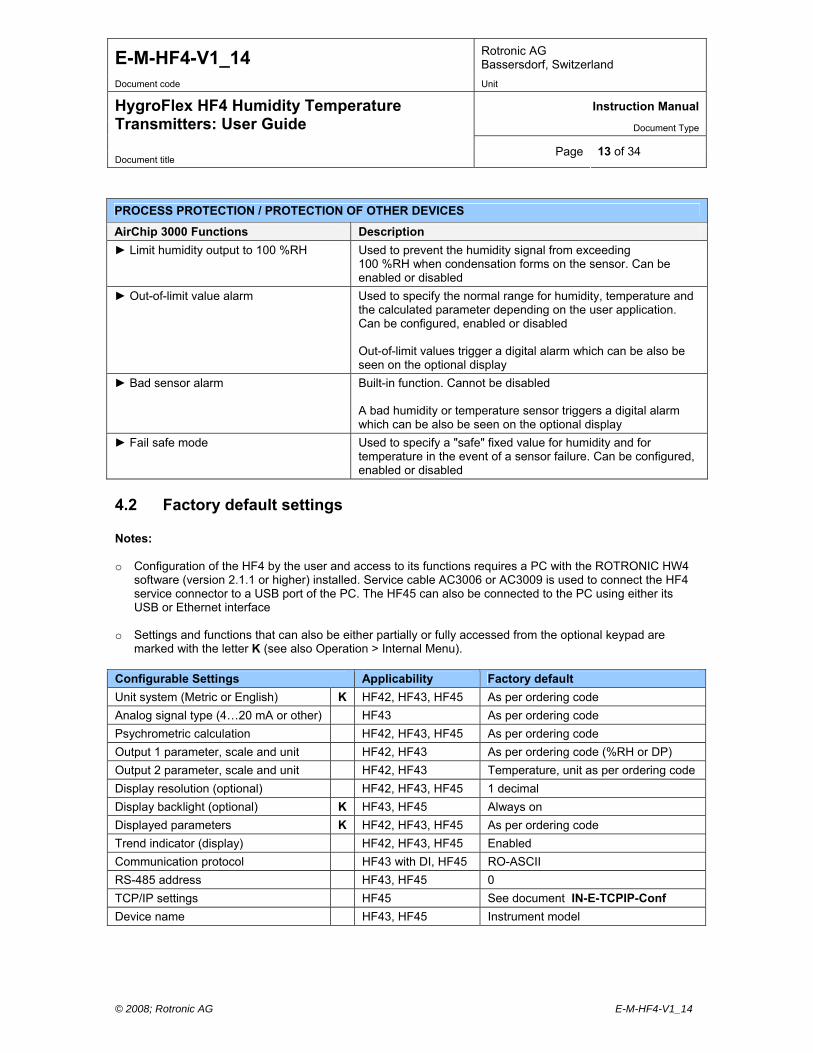
PROCESS PROTECTION / PROTECTION OF OTHER DEVICES
AirChip 3000 Functions Description
Limit humidity output to 100 %RH Used to prevent the humidity signal from exceeding 100 %RH when condensation forms on the sensor. Can be enabled or disabled
Out-of-limit value alarm Used to specify the normal range for humidity, temperature and the calculated parameter depending on the user application. Can be configured, enabled or disabled Out-of-limit values trigger a digital alarm which can be also be seen on the optional display
Bad sensor alarm Built-in function. Cannot be disabled A bad humidity or temperature sensor triggers a digital alarm which can be also be seen on the optional display
Fail safe mode Used to specify a "safe" fixed value for humidity and for temperature in the event of a sensor failure. Can be configured, enabled or disabled
4.2 Factory default settings Notes: o Configuration of the HF4 by the user and access to its functions requires a PC with the ROTRONIC HW4
software (version 2.1.1 or higher) installed. Service cable AC3006 or AC3009 is used to connect the HF4 service connector to a USB port of the PC. The HF45 can also be connected to the PC using either its USB or Ethernet interface
o Settings and functions that can also be either partially or fully accessed from the optional keypad are
marked with the letter K (see also Operation > Internal Menu). Configurable Settings Applicability Factory default
Unit system (Metric or English) K HF42, HF43, HF45 As per ordering code
Analog signal type (4…20 mA or other) HF43 As per ordering code
Psychrometric calculation HF42, HF43, HF45 As per ordering code
Output 1 parameter, scale and unit HF42, HF43 As per ordering code (%RH or DP)
Output 2 parameter, scale and unit HF42, HF43 Temperature, unit as per ordering code
Display resolution (optional) HF42, HF43, HF45 1 decimal
Display backlight (optional) K HF43, HF45 Always on
Displayed parameters K HF42, HF43, HF45 As per ordering code
Trend indicator (display) HF42, HF43, HF45 Enabled
Communication protocol HF43 with DI, HF45 RO-ASCII
RS-485 address HF43, HF45 0
TCP/IP settings HF45 See document IN-E-TCPIP-Conf
Device name HF43, HF45 Instrument model
E-M-HF4-V1_14 Rotronic AG Bassersdorf, Switzerland
Document code Unit
Instruction Manual
Document Type
HygroFlex HF4 Humidity Temperature Transmitters: User Guide
Document title Page 14 of 34
© 2008; Rotronic AG E-M-HF4-V1_14
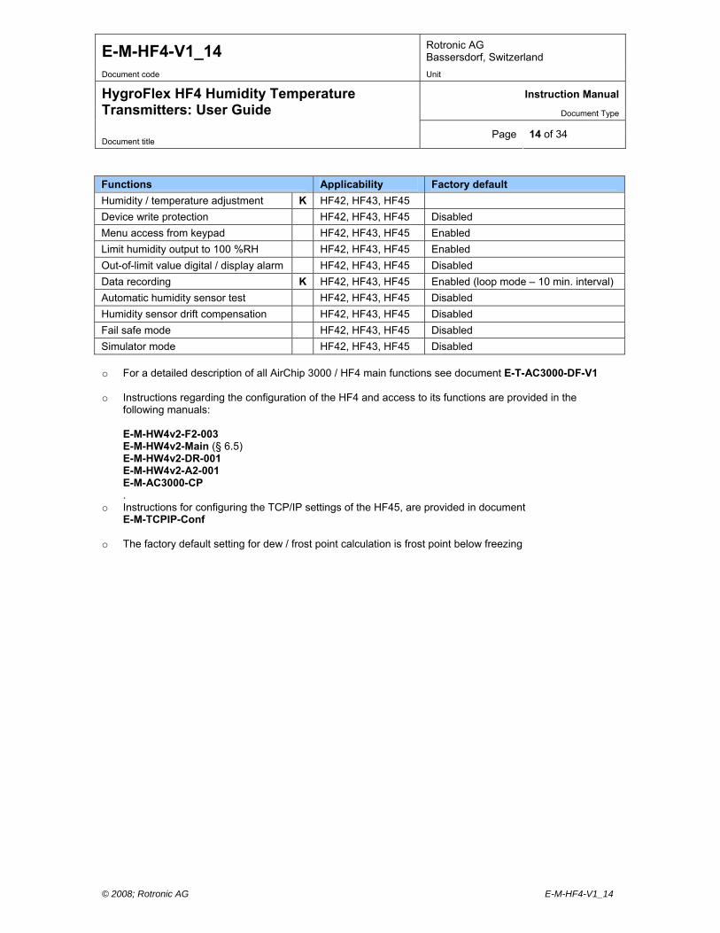
Functions Applicability Factory default
Humidity / temperature adjustment K HF42, HF43, HF45
Device write protection HF42, HF43, HF45 Disabled
Menu access from keypad HF42, HF43, HF45 Enabled
Limit humidity output to 100 %RH HF42, HF43, HF45 Enabled
Out-of-limit value digital / display alarm HF42, HF43, HF45 Disabled
Data recording K HF42, HF43, HF45 Enabled (loop mode – 10 min. interval)
Automatic humidity sensor test HF42, HF43, HF45 Disabled
Humidity sensor drift compensation HF42, HF43, HF45 Disabled
Fail safe mode HF42, HF43, HF45 Disabled
Simulator mode HF42, HF43, HF45 Disabled o For a detailed description of all AirChip 3000 / HF4 main functions see document E-T-AC3000-DF-V1
o Instructions regarding the configuration of the HF4 and access to its functions are provided in the
following manuals: E-M-HW4v2-F2-003 E-M-HW4v2-Main (§ 6.5) E-M-HW4v2-DR-001 E-M-HW4v2-A2-001 E-M-AC3000-CP .
o Instructions for configuring the TCP/IP settings of the HF45, are provided in document E-M-TCPIP-Conf
o The factory default setting for dew / frost point calculation is frost point below freezing

E-M-HF4-V1_14 Rotronic AG Bassersdorf, Switzerland
Document code Unit
Instruction Manual
Document Type
HygroFlex HF4 Humidity Temperature Transmitters: User Guide
Document title Page 15 of 34
© 2008; Rotronic AG E-M-HF4-V1_14
5 Mechanical installation
5.1 General guidelines Relative humidity is extremely dependent on temperature. Proper measurement of relative humidity requires that the probe and its sensors be at exactly the temperature of the environment to be measured. Because of this, the location where you choose to install the probe can have a significant effect on the performance of the instrument. The following guidelines should guarantee good instrument performance:
a) Select a representative location: install the probe where humidity, temperature and pressure conditions are representative of the environment to be measured.
b) Provide good air movement at the probe: air velocity of at least 200 ft/ minute (1 meter/second)
facilitates adaptation of the probe to changing temperature.
c) Avoid the following: (1) Close proximity of the probe to a heating element, a cooling coil, a cold or hot wall, direct exposure to sun rays, etc. (2) Close proximity of the probe to a steam injector, humidifier, direct exposure to precipitation, etc. (3) Unstable pressure conditions resulting from excessive air turbulence.
d) Immerse as much of the probe as possible in the environment to be measured.
e) Prevent the accumulation of condensation water at the level of the sensor leads. Install the
probe so that the probe tip is looking downward. If this is not possible, install the probe horizontally.
5.2 HF4 enclosure The HF4 enclosure consists of a base and a cover held together with 4 screws. To open the enclosure, use a metric 2.5 mm hex key. Prior to re-assembling the enclosure, verify that the red seal is sitting properly in its groove on the base.
5.3 Installation of the HF4 type D (through wall mount) Mounting position of the enclosure
Vertical: HF42 and HF43 type D without keypad and display
Horizontal: HF42 and HF43 type D with keypad and display HF45 type D
E-M-HF4-V1_14 Rotronic AG Bassersdorf, Switzerland
Document code Unit
Instruction Manual
Document Type
HygroFlex HF4 Humidity Temperature Transmitters: User Guide
Document title Page 16 of 34
© 2008; Rotronic AG E-M-HF4-V1_14
.4 Installation of the H
ounting position of the enclosure
ounting hardware
e HF4
ach screw. Insert a screw in each well and push to open the bottom of the well.
ng of 2 clamps that attach to the back of the enclosure with the screws provided.
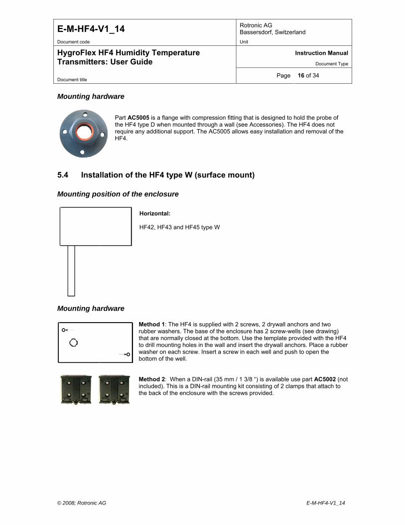
Mounting hardware
Part AC5005 is a flange with compression fitting that is designed to hold the probe of the HF4 type D when mounted through a wall (see Accessories). The HF4 does not require any additional support. The AC5005 allows easy installation and removal of theHF4.
5 F4 type W (surface mount) M
Horizontal:
42, HF43 and HF45 type W HF
M Method 1: The HF4 is supplied with 2 screws, 2 drywall anchors and two rubber washers. The base of the enclosure has 2 screw-wells (see drawing) that are normally closed at the bottom. Use the template provided with thto drill mounting holes in the wall and insert the drywall anchors. Place a rubber washer on e
Method 2: When a DIN-rail (35 mm / 1 3/8 “) is available use part AC5002 (not included). This is a DIN-rail mounting kit consisti
E-M-HF4-V1_14 Rotronic AG Bassersdorf, Switzerland
Document code Unit
Instruction Manual
Document Type
HygroFlex HF4 Humidity Temperature Transmitters: User Guide
Document title Page 17 of 34
© 2008; Rotronic AG E-M-HF4-V1_14
6 Electrical installation
6.1 General wiring guidelines Power supply wiring Heavy machinery and instrumentation should not share the same power supply wiring. If this cannot be avoided, noise filters and surge protectors should be used. Most UPS devices have those features already integrated. General guidelines for signal cables The following guidelines are derived from European Standard EN 50170 for the transmission of signals by copper wires. When planning an installation, the rules provided by EN 50170 should be followed under consideration of local circumstances to determine the position of machines and equipment. All ROTRONIC products are tested for Electromagnetic Compatibility according to EMC Directive 2004/106/EG and following European standards:
- EN 61000-6-1: 2001, EN 61000-6-2: 2005 - EN 61000-6-3: 2005, EN 61000-6-4: 2001 + A11
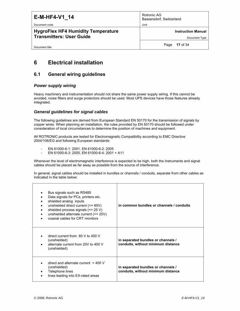
Whenever the level of electromagnetic interference is expected to be high, both the instruments and signal cables should be placed as far away as possible from the source of interference. In general, signal cables should be installed in bundles or channels / conduits, separate from other cables as indicated in the table below:
Bus signals such as RS485 Data signals for PCs, printers etc. shielded analog inputs unshielded direct current (<= 60V) shielded process signals (<= 25 V) unshielded alternate current (<= 25V) coaxial cables for CRT monitors
in common bundles or channels / conduits
direct current from 60 V to 400 V (unshielded)
alternate current from 25V to 400 V (unshielded)
in separated bundles or channels / conduits, without minimum distance
direct and alternate current > 400 V (unshielded)
Telephone lines lines leading into EX-rated areas
in separated bundles or channels / conduits, without minimum distance

E-M-HF4-V1_14 Rotronic AG Bassersdorf, Switzerland
Document code Unit
Instruction Manual
Document Type
HygroFlex HF4 Humidity Temperature Transmitters: User Guide
Document title Page 18 of 34
© 2008; Rotronic AG E-M-HF4-V1_14
tal
Lightning protection Cabling in areas with a risk of lightning requires a lightning protection. For cabling underground in between buildings, we recommend the use of special fiber optic cables. If this is not possible, use copper cables that are suitable for underground installation.
6.2 Guidelines for RS-485 wiring (HF45) See document E-DV04-RS485.01: RS485 Network Installation and Start-up Guidelines
6.3 Cable grip and cable specifications The HF4 is supplied either with one M16 sealing cable grip or with a ½” conduit adapter. The M16 cable grip provides effective sealing only with cables having the proper outside diameter. Preferably, use a cable with an outside diameter of 6 to 7 mm (0.236 to 0.275 inch) with 18 AWG wires.
6.4 Wiring
6.4.1 HF42: 2-wire, loop powered transmitter Electrical diagram
The maximum permissible cable length connecting the HF42 to other devices is determined by the toresistance resulting from the addition of the cable resistance and that of the devices connected in series with the unit. This resistance should not exceed 500 ohms.
Terminal block diagram
Terminals Description
K2-2: T-OUT Temperature output (+) OUT-2
K2-1: V+ Power supply: 10…28 VDC (+)
K1-2: H-OUT Relative humidity or dew point (+) OUT-1
K1-1: V+ Power supply: 10…28 VDC (+)
Note: connect the + of the power supply to only one of the V+ terminals. The two terminals marked V+ are internally connected.
E-M-HF4-V1_14 Rotronic AG Bassersdorf, Switzerland
Document code Unit
Instruction Manual
Document Type
HygroFlex HF4 Humidity Temperature Transmitters: User Guide
Document title Page 19 of 34
© 2008; Rotronic AG E-M-HF4-V1_14
000 of
Measuring humidity or temperature only Unless configured to measure either humidity only or temperature only, proper operation of the HF42 requires both current loops to be closed. The HF42 can be directly ordered from the factory to measure either humidity or temperature only. When necessary, any unused output of the HF42 can be disabled with the ROTRONIC HW4 software. When the HF42 is configured with one of the two outputs disabled, close only the loop that is being used.
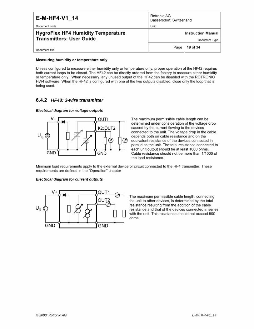
6.4.2 HF43: 3-wire transmitter Electrical diagram for voltage outputs
The maximum permissible cable length can bedetermined under consideration of the voltage dropcaused by the current flowing to the devicesconnected to the unit. The voltage drop in the cabledepends both on cable resistance and on theequivalent resistance of the devices connected in parallel to the unit. The total resistance connected toeach unit output should be at least 1000 ohms. Cable resistance should not be more than 1/1
the load resistance. Minimum load requirements apply to the external device or circuit connected to the HF4 transmitter. These requirements are defined in the “Operation” chapter Electrical diagram for current outputs
The maximum permissible cable length, connecting the unit to other devices, is determined by the totalresistance resulting from the addition of the cableresistance and that of the devices connected in serieswith the unit. This resistance should not exceed 500 ohms.
E-M-HF4-V1_14 Rotronic AG Bassersdorf, Switzerland
Document code Unit
Instruction Manual
Document Type
HygroFlex HF4 Humidity Temperature Transmitters: User Guide
Document title Page 20 of 34
© 2008; Rotronic AG E-M-HF4-V1_14
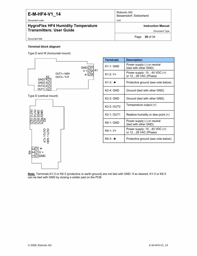
Terminal block diagram Type D and W (horizontal mount)
Terminals Description
K1-1: GND Power supply (-) or neutral (tied with other GND)
K1-2: V+ Power supply: 15…40 VDC (+) or 12…28 VAC (Phase)
K1-3: - Protective ground (see note below)
K2-4: GND Ground (tied with other GND)
K2-3: GND Ground (tied with other GND)
K2-2: OUT2 Temperature output (+)
K2-1: OUT1 Relative humidity or dew point (+)
K6-1: GND Power supply (-) or neutral (tied with other GND)
K6-1: V+ Power supply: 15…40 VDC (+) or 12…28 VAC (Phase)
K6-3: - Protective ground (see note below)
Type D (vertical mount)
Note: Terminals K1-3 or K6-3 (protective or earth ground) are not tied with GND. If so desired, K1-3 or K6-3 can be tied with GND by closing a solder pad on the PCB
E-M-HF4-V1_14 Rotronic AG Bassersdorf, Switzerland
Document code Unit
Instruction Manual
Document Type
HygroFlex HF4 Humidity Temperature Transmitters: User Guide
Document title Page 21 of 34
© 2008; Rotronic AG E-M-HF4-V1_14
Measuring humidity or temperature only Operation of the HF43 does not require both current loops to be closed. When using the HF43 to measure either humidity only or temperature only, close only the loop that is being used. Using the ROTRONIC HW4 software, any unused output of the HF43 can be disabled.
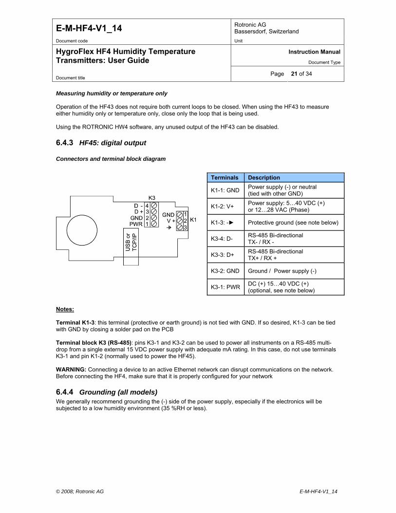
6.4.3 HF45: digital output Connectors and terminal block diagram
Terminals Description
K1-1: GND Power supply (-) or neutral (tied with other GND)
K1-2: V+ Power supply: 5…40 VDC (+) or 12…28 VAC (Phase)
K1-3: - Protective ground (see note below)
K3-4: D- RS-485 Bi-directional TX- / RX -
K3-3: D+ RS-485 Bi-directional TX+ / RX +
K3-2: GND Ground / Power supply (-)
K3-1: PWR DC (+) 15…40 VDC (+) (optional, see note below)
Notes: Terminal K1-3: this terminal (protective or earth ground) is not tied with GND. If so desired, K1-3 can be tied with GND by closing a solder pad on the PCB Terminal block K3 (RS-485): pins K3-1 and K3-2 can be used to power all instruments on a RS-485 multi-drop from a single external 15 VDC power supply with adequate mA rating. In this case, do not use terminals K3-1 and pin K1-2 (normally used to power the HF45). WARNING: Connecting a device to an active Ethernet network can disrupt communications on the network. Before connecting the HF4, make sure that it is properly configured for your network
6.4.4 Grounding (all models) We generally recommend grounding the (-) side of the power supply, especially if the electronics will be subjected to a low humidity environment (35 %RH or less).
E-M-HF4-V1_14 Rotronic AG Bassersdorf, Switzerland
Document code Unit
Instruction Manual
Document Type
HygroFlex HF4 Humidity Temperature Transmitters: User Guide
Document title Page 22 of 34
© 2008; Rotronic AG E-M-HF4-V1_14
7 Operation
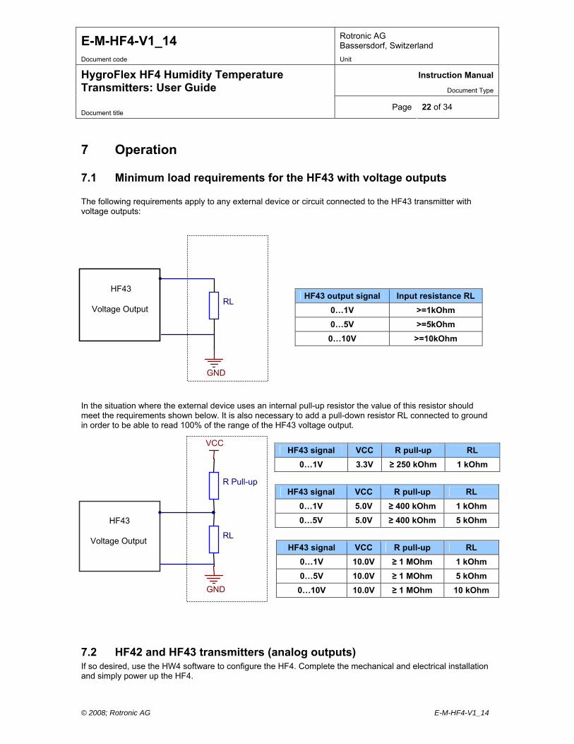
7.1 Minimum load requirements for the HF43 with voltage outputs The following requirements apply to any external device or circuit connected to the HF43 transmitter with voltage outputs: In the situation where the external device uses an internal pull-up resistor the value of this resistor should meet the requirements shown below. It is also necessary to add a pull-down resistor RL connected to ground in order to be able to read 100% of the range of the HF43 voltage output.
7.2 HF42 and HF43 transmitters (analog outputs) If so desired, use the HW4 software to configure the HF4. Complete the mechanical and electrical installation and simply power up the HF4.
HF43 output signal Input resistance RL
0…1V >=1kOhm
0…5V >=5kOhm
0…10V >=10kOhm
HF43 signal VCC R pull-up RL
0…1V 3.3V ≥ 250 kOhm 1 kOhm
HF43 signal VCC R pull-up RL
0…1V 5.0V ≥ 400 kOhm 1 kOhm
0…5V 5.0V ≥ 400 kOhm 5 kOhm
HF43 signal VCC R pull-up RL
0…1V 10.0V ≥ 1 MOhm 1 kOhm
0…5V 10.0V ≥ 1 MOhm 5 kOhm
0…10V 10.0V ≥ 1 MOhm 10 kOhm
RL
GND
HF43
Voltage Output
R Pull-up
RL
GND
VCC
Voltage Output
HF43
E-M-HF4-V1_14 Rotronic AG Bassersdorf, Switzerland
Document code Unit
Instruction Manual
Document Type
HygroFlex HF4 Humidity Temperature Transmitters: User Guide
Document title Page 23 of 34
© 2008; Rotronic AG E-M-HF4-V1_14
7.3 HF45 (digital output) Configuration and full access to all HF45 functions requires a PC with the ROTRONIC HW4 software installed. Starting with firmware version 1.3, the HF45 offers several communication protocol options that allow users to read the measurement data without the HW4 software. When using the standard RO-ASCII protocol, access to some of the HF45 functions is also possible without HW4. For details, see document E-M-AC3000-CP. IMPORTANT: Depending on the type of digital interface, either the PC or the HF45 must be configured by the user as indicated below. a) USB network connection Prior to connecting the HF45 to a USB port you must install the ROTRONIC USB driver on the HW4 PC. For instructions see the HW4 manual E-M-HW4v2-Main (§ 6.3) b) Ethernet (TCP/IP) network connection (wired or wireless) Prior to connecting the HF45 to an active Ethernet network you must configure the HF45 TCP/IP settings. For instructions see the HW4 manual E-M-HW4v2-Main (§ 6.4) and technical note E-M-TCPIP-Conf WARNING: Connecting a device to an active Ethernet network can disrupt communications on the network. Before connecting the HF4, make sure that it is properly configured for your network c) RS-485 serial interface (multi-drop) Instructions for using the HF45 with a RS-485 network are provided in the following manuals: E-M-HW4v2-Main (§ 6.5), E-M-HW4v2-F2-003 and E-DV04-RS485.01. Notes: o Instruments connected to the same RS-485 network must use the same baud rate and each instrument
must be given a unique RS-485 address o RS-485 Compatibility: The communications protocol used by the HF45 and other AirChip 3000 products
is not compatible with the protocol used by the previous generation of ROTRONIC products. Do not connect legacy products and AirChip 3000 products to the same RS-485 multi-drop network.
The specifications of the RS-485 interface are as follows: Baud rate : 19200 Parity : none Data bits : 8 Stop bits : 1

E-M-HF4-V1_14 Rotronic AG Bassersdorf, Switzerland
Document code Unit
Instruction Manual
Document Type
HygroFlex HF4 Humidity Temperature Transmitters: User Guide
Document title Page 24 of 34
© 2008; Rotronic AG E-M-HF4-V1_14
7.4 Internal menu (optional keypad and display) Note: Unauthorized access to the menu can be prevented by disabling the “display menu” setting (use the HW4 software > Device Manager > Display)
Menu navigation keys + / - Change value up / down
ENTER key: menu item selection
MENU key: open / close menu Main Menu Menu Items Selections / Information Notes
Settings
Record On / Off Data recording (max. 2000 values)
Unit °C / °F Temperature / dew or frost point
Back Light Key Press / On / Off Display backlight mode
Device Information
Version Firmware version
Serial Nbr Serial number
Address RS-485 address
Type Device type
Name Device name User defined
SensorTest Humidity sensor status Off / Good / SQ-Tuned / Bad
Humidity Adjust
RefValue Humidity reference value ± 0.1 %RH steps
<Adjust> 1-point adjustment only (offset)
Temperature Adjust
RefValue Temperature reference value ± 0.1 ˚C steps
<Adjust> 1-point adjustment only (offset) o Record: both the recording mode (start / stop and the log interval cannot be changed from the menu and
are as configured with the ROTRONIC HW4 software o SensorTest: Off means that the humidity sensor has not been tested due to the configuration settings of
the test. For a description of the automatic humidity sensor test and drift compensation (SQ-tuning) see documents E-T-AC3000-DF-V1 and E-M-HW4v2-F2-003
7.5 Displayed parameters (optional keypad and display) When the menu is not active, press the ENTER key to change which parameters are shown on the display:
o Relative humidity and temperature o Dew / frost point and temperature (when the calculated parameter is enabled)
E-M-HF4-V1_14 Rotronic AG Bassersdorf, Switzerland
Document code Unit
Instruction Manual
Document Type
HygroFlex HF4 Humidity Temperature Transmitters: User Guide
Document title Page 25 of 34
© 2008; Rotronic AG E-M-HF4-V1_14
8 Maintenance
8.1 Service cable Cable AC3006 is used to connect the HF4 to a USB port of a PC running the ROTRONIC HW4 software. As an alternative, cable AC2001 is used to connect the HF4 to a probe input of the HP23 hand-held
calibrator. For service purposes, the HP23 offers essentially the same functionality as the HW4 software.
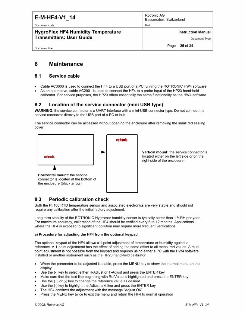
8.2 Location of the service connector (mini USB type) WARNING: the service connector is a UART interface with a mini-USB connector type. Do not connect the service connector directly to the USB port of a PC or hub. The service connector can be accessed without opening the enclosure after removing the small red sealing cover.
HF32
Vertical mount: the service connector islocated either on the left side or on theright side of the enclosure.
Horizontal mount: the service connector is located at the bottom of the enclosure (black arrow)
8.3 Periodic calibration check Both the Pt 100 RTD temperature sensor and associated electronics are very stable and should not require any calibration after the initial factory adjustment. Long term stability of the ROTRONIC Hygromer humidity sensor is typically better than 1 %RH per year. For maximum accuracy, calibration of the HF4 should be verified every 6 to 12 months. Applications where the HF4 is exposed to significant pollution may require more frequent verifications. a) Procedure for adjusting the HF4 from the optional keypad The optional keypad of the HF4 allows a 1-point adjustment of temperature or humidity against a reference. A 1-point adjustment has the effect of adding the same offset to all measured values. A multi-point adjustment is not possible from the keypad and requires using either a PC with the HW4 software installed or another instrument such as the HP23 hand-held calibrator. When the parameter to be adjusted is stable, press the MENU key to show the internal menu on the
display Use the (-) key to select either H-Adjust or T-Adjust and press the ENTER key Make sure that the text line beginning with RefValue is highlighted and press the ENTER key Use the (+) or (-) key to change the reference value as desired Use the (-) key to highlight the Adjust text line and press the ENTER key The HF4 confirms the adjustment with the message “Adjust OK” Press the MENU key twice to exit the menu and return the HF4 to normal operation
E-M-HF4-V1_14 Rotronic AG Bassersdorf, Switzerland
Document code Unit
Instruction Manual
Document Type
HygroFlex HF4 Humidity Temperature Transmitters: User Guide
Document title Page 26 of 34
© 2008; Rotronic AG E-M-HF4-V1_14
Notes: o The calibration point is automatically deleted from the probe memory after an adjustment o Because the HF4 has no real time clock, the date of the adjustment is not written to the HF4. If
retaining the adjustment date is important, use the HW4 software to adjust the HF4. b) Procedure for adjusting the HF4 with the ROTRONIC HW4 software: Use cable AC3006 to connect the service connector of the HF4 to a USB port of a PC with the HW4
software installed. Note that the ROTRONIC USB driver must be installed on the PC as explained in the HW4 manual E-M-HW4v2-Main. In the case of the HF45, a connection with the PC can be established via the USB (ROTRONIC USB driver) or Ethernet interface.
Start HW4 on the PC and search for the HF4 (HW4 Main Menu Bar > Devices and Groups > Search for USB Masters).
After finding the HF4 with HW4, expand the device tree to see the HF4 functions. Select Probe Adjustment.
For further instructions see HW4 manual E-M-HW4v2-A2-001
8.4 Cleaning or replacing the dust filter Depending on the application, the dust filter may require cleaning from time to time, Cleaning should be done without removing the filter from the probe. Clean the filter with a fine brush. If this is not sufficient, the filter should be replaced. To do this, unscrew the filter from the probe. Before putting on a new dust filter, check the alignment of both sensors with the probe. The wires that connect the sensors to the probe are very thin and bend easily. If this happens, correct the alignment by holding the sensor very gently with a pair of small flat nosed pliers.
8.5 Validation of the output signals transmission If so desired, transmission of the HF4 output signals can be validated by using the simulator function. The HW4 software is required to enable and configure this function. When this function is enabled the HF4 generates fixed digital and analog signals as specified by the user. For instructions see document E-M-HW4v2-F2-003
9 Firmware updates Firmware updates will be available on the ROTRONIC website for downloading. Firmware files are given a name that shows both to which device the file applies and the version number of the firmware. All firmware files have the extension HEX. Procedure for updating the firmware: Use cable AC3006 to connect the service connector of the HF4 to a USB port of a PC with the
ROTRONIC HW4 software installed. Note that the ROTRONIC USB driver must be installed on the PC as explained in the HW4 manual E-M-HW4v2-Main. In the case of the HF45, a connection with the PC can be established via the USB (ROTRONIC USB driver) or Ethernet interface.
Copy the firmware update file from the ROTRONIC website to the PC. Start HW4 software on the PC and search for the HF4 (HW4 Main Menu Bar > Devices and Groups
> Search for USB Masters). After finding the HF4, expand the device tree to see the HF4 functions. Select Device Manager. In
the Device Manager menu bar select Tools > Firmware Update. For instructions see document E-M-HW4v2-F2-003
E-M-HF4-V1_14 Rotronic AG Bassersdorf, Switzerland
Document code Unit
Instruction Manual
Document Type
HygroFlex HF4 Humidity Temperature Transmitters: User Guide
Document title Page 27 of 34
© 2008; Rotronic AG E-M-HF4-V1_14
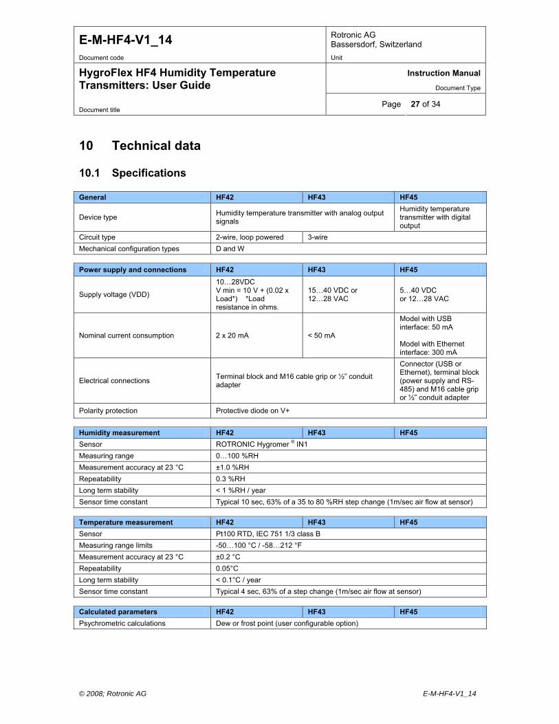
10 Technical data
10.1 Specifications General HF42 HF43 HF45
Device type Humidity temperature transmitter with analog output signals
Humidity temperature transmitter with digital output
Circuit type 2-wire, loop powered 3-wire
Mechanical configuration types D and W
Power supply and connections HF42 HF43 HF45
Supply voltage (VDD)
10…28VDC V min = 10 V + (0.02 x Load*) *Load resistance in ohms.
15…40 VDC or 12…28 VAC
5…40 VDC or 12…28 VAC
Nominal current consumption 2 x 20 mA < 50 mA
Model with USB interface: 50 mA Model with Ethernet interface: 300 mA
Electrical connections Terminal block and M16 cable grip or ½” conduit adapter
Connector (USB or Ethernet), terminal block (power supply and RS-485) and M16 cable grip or ½” conduit adapter
Polarity protection Protective diode on V+
Humidity measurement HF42 HF43 HF45
Sensor ROTRONIC Hygromer ® IN1
Measuring range 0…100 %RH
Measurement accuracy at 23 °C ±1.0 %RH
Repeatability 0.3 %RH
Long term stability < 1 %RH / year
Sensor time constant Typical 10 sec, 63% of a 35 to 80 %RH step change (1m/sec air flow at sensor)
Temperature measurement HF42 HF43 HF45
Sensor Pt100 RTD, IEC 751 1/3 class B
Measuring range limits -50…100 °C / -58…212 °F
Measurement accuracy at 23 °C ±0.2 °C
Repeatability 0.05°C
Long term stability < 0.1°C / year
Sensor time constant Typical 4 sec, 63% of a step change (1m/sec air flow at sensor)
Calculated parameters HF42 HF43 HF45
Psychrometric calculations Dew or frost point (user configurable option)
E-M-HF4-V1_14 Rotronic AG Bassersdorf, Switzerland
Document code Unit
Instruction Manual
Document Type
HygroFlex HF4 Humidity Temperature Transmitters: User Guide
Document title Page 28 of 34
© 2008; Rotronic AG E-M-HF4-V1_14
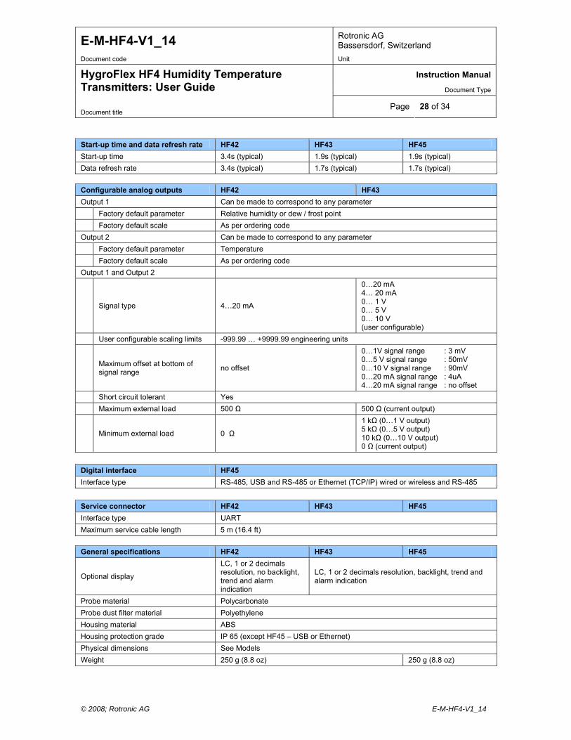
Start-up time and data refresh rate HF42 HF43 HF45
Start-up time 3.4s (typical) 1.9s (typical) 1.9s (typical)
Data refresh rate 3.4s (typical) 1.7s (typical) 1.7s (typical)
Configurable analog outputs HF42 HF43
Output 1 Can be made to correspond to any parameter
Factory default parameter Relative humidity or dew / frost point
Factory default scale As per ordering code
Output 2 Can be made to correspond to any parameter
Factory default parameter Temperature
Factory default scale As per ordering code
Output 1 and Output 2
Signal type 4…20 mA
0…20 mA 4… 20 mA 0… 1 V 0… 5 V 0… 10 V (user configurable)
User configurable scaling limits -999.99 … +9999.99 engineering units
Maximum offset at bottom of signal range
no offset
0…1V signal range : 3 mV 0…5 V signal range : 50mV 0…10 V signal range : 90mV 0…20 mA signal range : 4uA 4…20 mA signal range : no offset
Short circuit tolerant Yes
Maximum external load 500 Ω 500 Ω (current output)
Minimum external load 0 Ω
1 kΩ (0…1 V output) 5 kΩ (0…5 V output) 10 kΩ (0…10 V output) 0 Ω (current output)
Digital interface HF45
Interface type RS-485, USB and RS-485 or Ethernet (TCP/IP) wired or wireless and RS-485
Service connector HF42 HF43 HF45
Interface type UART
Maximum service cable length 5 m (16.4 ft)
General specifications HF42 HF43 HF45
Optional display
LC, 1 or 2 decimals resolution, no backlight, trend and alarm indication
LC, 1 or 2 decimals resolution, backlight, trend and alarm indication
Probe material Polycarbonate
Probe dust filter material Polyethylene
Housing material ABS
Housing protection grade IP 65 (except HF45 – USB or Ethernet)
Physical dimensions See Models
Weight 250 g (8.8 oz) 250 g (8.8 oz)
E-M-HF4-V1_14 Rotronic AG Bassersdorf, Switzerland
Document code Unit
Instruction Manual
Document Type
HygroFlex HF4 Humidity Temperature Transmitters: User Guide
Document title Page 29 of 34
© 2008; Rotronic AG E-M-HF4-V1_14
Conformity with standards HF42 HF43 HF45
CE / EMC immunity EMC Directive 2004/108/EG: EN 61000-6-1: 2001, EN 61000-6-2: 2005 EN 61000-6-3: 2005, EN 61000-6-4: 2001 + A11
Solder type Lead free (RoHS directive)
Fire protection class Corresponds to UL94-HB
FDA / GAMP directives compatible
Environmental limits HF42 HF43 HF45
Storage and transit -50…+70 °C / -20...+70 °C (models with display), 0…100 %RH, non condensing
Operating limits at electronics -40 … +60 °C / -10….60 °C (models with display), 0…100 %RH, non condensing
Temperature limits at probe -50…+100 °C (valid for type D)
Maximum humidity at sensor 100 %RH up to 80 °C (176 °F) 75 %RH at 100 °C (212 °F)
Maximum air velocity at probe 20 m/s (3,935 ft /min)
Critical environments Humidity sensor: as per DV04-14.0803.02 - Critical chemicals
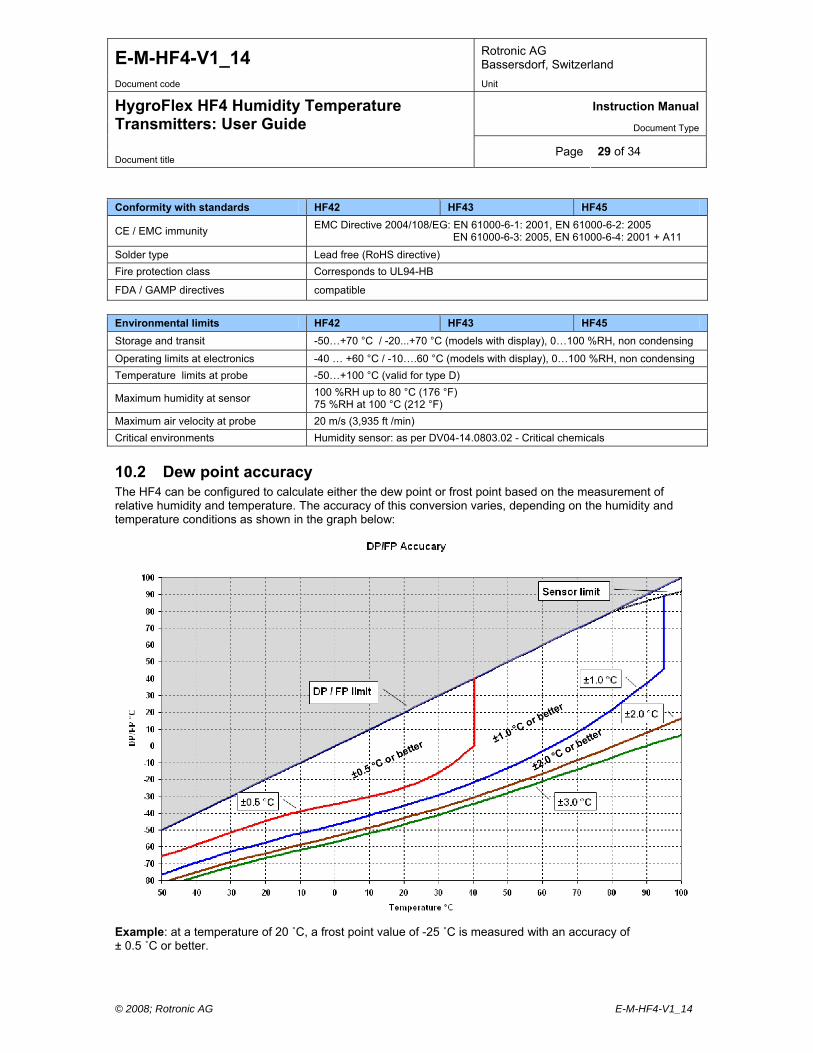
10.2 Dew point accuracy The HF4 can be configured to calculate either the dew point or frost point based on the measurement of relative humidity and temperature. The accuracy of this conversion varies, depending on the humidity and temperature conditions as shown in the graph below:
Example: at a temperature of 20 ˚C, a frost point value of -25 ˚C is measured with an accuracy of ± 0.5 ˚C or better.
E-M-HF4-V1_14 Rotronic AG Bassersdorf, Switzerland
Document code Unit
Instruction Manual
Document Type
HygroFlex HF4 Humidity Temperature Transmitters: User Guide
Document title Page 30 of 34
© 2008; Rotronic AG E-M-HF4-V1_14
11 Accessories
11.1 Configuration and communication software The ROTRONIC HW4 software (version 2.1.0 or higher) allows configuring the HF4. HW4 is compatible with Windows XP, Vista and NT4 with SP6a or higher. For more details see separate instruction manual provided with the software.
Order Code Description
HW4-E HW4 software, Standard Edition ( single user)
HW4-P HW4 Professional Edition, ERES regulations compliant (FDA / GAMP), multi user
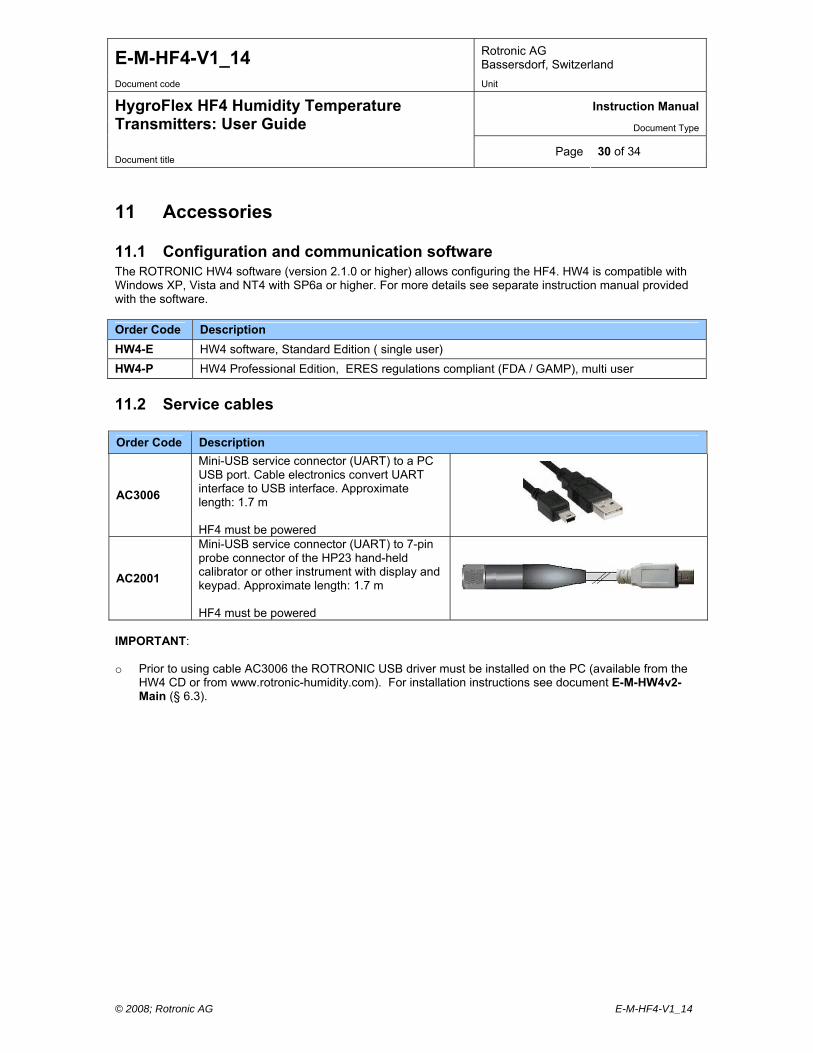
11.2 Service cables
Order Code Description
AC3006
Mini-USB service connector (UART) to a PC USB port. Cable electronics convert UART interface to USB interface. Approximate length: 1.7 m HF4 must be powered
AC2001
Mini-USB service connector (UART) to 7-pin probe connector of the HP23 hand-held calibrator or other instrument with display and keypad. Approximate length: 1.7 m HF4 must be powered
IMPORTANT: o Prior to using cable AC3006 the ROTRONIC USB driver must be installed on the PC (available from the
HW4 CD or from www.rotronic-humidity.com). For installation instructions see document E-M-HW4v2-Main (§ 6.3).

E-M-HF4-V1_14 Rotronic AG Bassersdorf, Switzerland
Document code Unit
Instruction Manual
Document Type
HygroFlex HF4 Humidity Temperature Transmitters: User Guide
Document title Page 31 of 34
© 2008; Rotronic AG E-M-HF4-V1_14
11.3 USB / RS-485 converter cable
Order Code Description
AC3010
USB / RS-485 converter. Allows connecting the RS-485 port of a HF45 transmitter with digital option to the USB port of a PC. Within the RS-485 network, the HF45 behaves as a slave.
IMPORTANT: Prior to using cable AC3010, the ROTRONIC USB driver must be installed on the PC (available from the HW4 CD or from www.rotronic-humidity.com). For installation instructions see document E-M-HW4v2-Main (§ 6.3).
11.4 Mounting hardware
Order Code Description
AC5002
DIN-rail mounting kit (consists of 2 clamps that attach to the back of the enclosure with the screws provided). DIN-rail (35 mm / 1 3/8”) not included
AC5005
Mounting flange with compression fitting for (15 mm / 0.6” diameter probe). Use for though wall installation of the HF4 type D Maximum temperature 100 °C (212°F)
AC5001
Sleeve for adapting a 15 mm / 0.6” diameter probe to a 25 mm / 1.0 “ diameter through-wall mounting hole (HF42 and HF43 type D, vertical mounting position) Facilitates the replacement of older products with a 25 mm probe diameter
E-M-HF4-V1_14 Rotronic AG Bassersdorf, Switzerland
Document code Unit
Instruction Manual
Document Type
HygroFlex HF4 Humidity Temperature Transmitters: User Guide
Document title Page 32 of 34
© 2008; Rotronic AG E-M-HF4-V1_14
11.5 Calibration accessories
Order Code Description
EA00-SCS 0.5 %RH humidity std, SCS cert., pack of 5
EA05-SCS 5 %RH humidity std, SCS cert., pack of 5
EA10-SCS 10 %RH humidity std, SCS cert., pack of 5
EA20-SCS 20 %RH humidity std, SCS cert., pack of 5
EA35-SCS 35 %RH humidity std, SCS cert., pack of 5
EA50-SCS 50 %RH humidity std, SCS cert., pack of 5
EA65-SCS 65 %RH humidity std, SCS cert., pack of 5
EA80-SCS 80 %RH humidity std, SCS cert., pack of 5
EA95-SCS 95 %RH humidity std, SCS cert., pack of 5
ER-15 Calibration device for 15mm diameter probes
For instructions regarding the ROTRONIC humidity standards and calibration devices see document E-M-CalBasics.
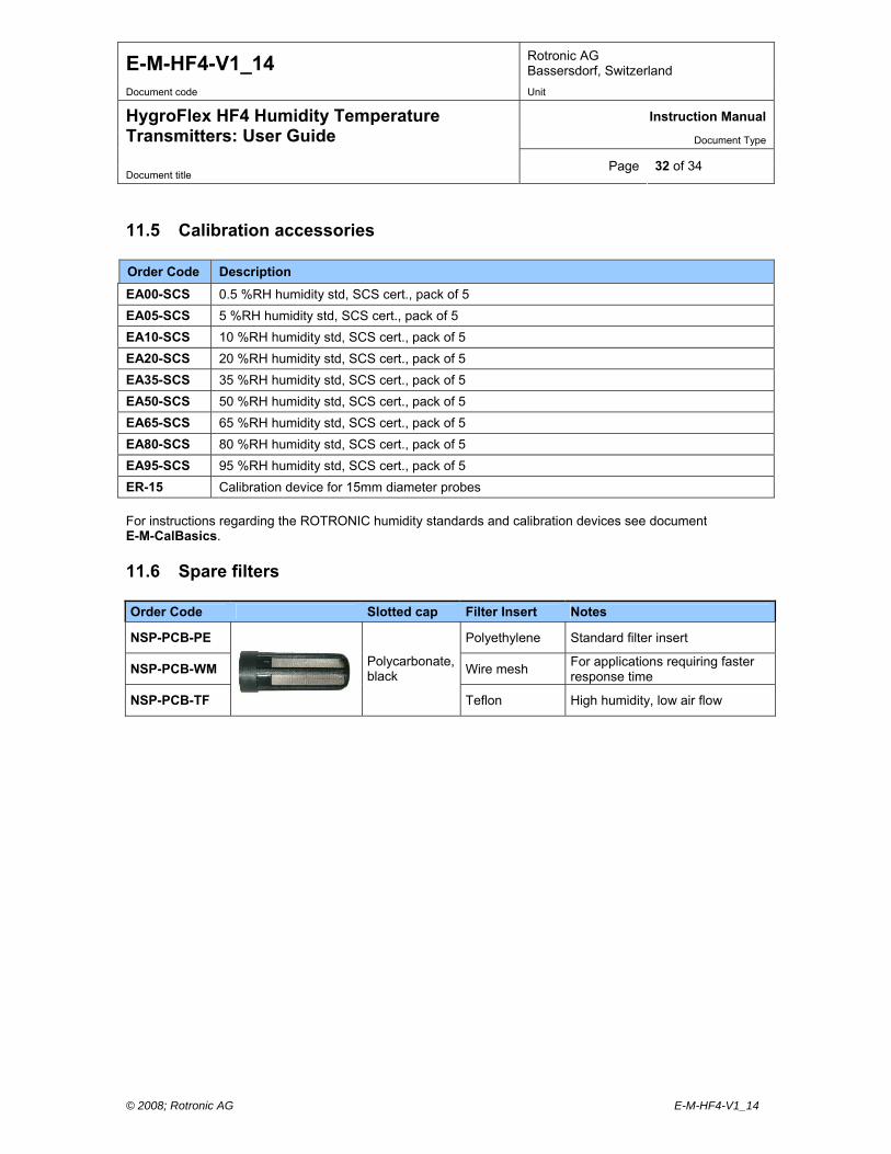
11.6 Spare filters
Order Code Slotted cap Filter Insert Notes
NSP-PCB-PE Polyethylene Standard filter insert
NSP-PCB-WM Wire mesh For applications requiring faster response time
NSP-PCB-TF
Polycarbonate, black
Teflon High humidity, low air flow
E-M-HF4-V1_14 Rotronic AG Bassersdorf, Switzerland
Document code Unit
Instruction Manual
Document Type
HygroFlex HF4 Humidity Temperature Transmitters: User Guide
Document title Page 33 of 34
© 2008; Rotronic AG E-M-HF4-V1_14
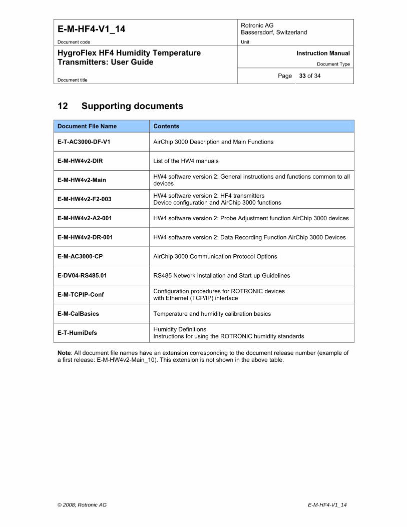
12 Supporting documents
Document File Name Contents
E-T-AC3000-DF-V1 AirChip 3000 Description and Main Functions
E-M-HW4v2-DIR List of the HW4 manuals
E-M-HW4v2-Main HW4 software version 2: General instructions and functions common to all devices
E-M-HW4v2-F2-003 HW4 software version 2: HF4 transmitters Device configuration and AirChip 3000 functions
E-M-HW4v2-A2-001 HW4 software version 2: Probe Adjustment function AirChip 3000 devices
E-M-HW4v2-DR-001 HW4 software version 2: Data Recording Function AirChip 3000 Devices
E-M-AC3000-CP AirChip 3000 Communication Protocol Options
E-DV04-RS485.01 RS485 Network Installation and Start-up Guidelines
E-M-TCPIP-Conf Configuration procedures for ROTRONIC devices with Ethernet (TCP/IP) interface
E-M-CalBasics Temperature and humidity calibration basics
E-T-HumiDefs Humidity Definitions Instructions for using the ROTRONIC humidity standards
Note: All document file names have an extension corresponding to the document release number (example of a first release: E-M-HW4v2-Main_10). This extension is not shown in the above table.
E-M-HF4-V1_14 Rotronic AG Bassersdorf, Switzerland
Document code Unit
Instruction Manual
Document Type
HygroFlex HF4 Humidity Temperature Transmitters: User Guide
Document title Page 34 of 34
© 2008; Rotronic AG E-M-HF4-V1_14
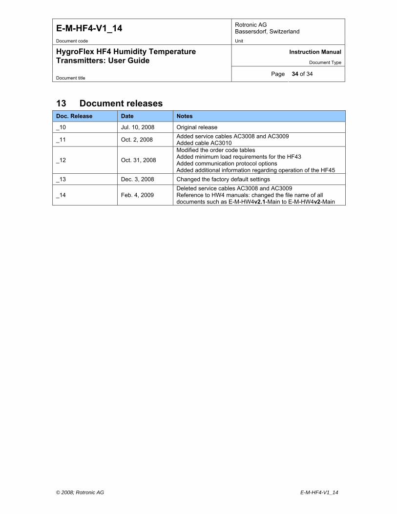
13 Document releases Doc. Release Date Notes
_10 Jul. 10, 2008 Original release
_11 Oct. 2, 2008 Added service cables AC3008 and AC3009 Added cable AC3010
_12 Oct. 31, 2008
Modified the order code tables Added minimum load requirements for the HF43 Added communication protocol options Added additional information regarding operation of the HF45
_13 Dec. 3, 2008 Changed the factory default settings
_14 Feb. 4, 2009 Deleted service cables AC3008 and AC3009 Reference to HW4 manuals: changed the file name of all documents such as E-M-HW4v2.1-Main to E-M-HW4v2-Main