Embed Size (px)
Citation preview

HyperMesh Basic Training
Volume 2

For technical support, contact us at: PHONE (248) 614-2425. Mon – Thurs: 8:00 AM to 7:00 PM (EST).
Fri: 8:00 AM to 5:00 PM (EST). Select HyperMesh Support FAX (248) 614-2411 EMAIL [email protected] WEB www.altair.com FTP Site: ADDRESS ftp.altair.com or ftp2.altair.com LOGIN ftp PASSWORD <your email address>
Copyright © 2003 Altair Engineering, Inc., All rights reserved.
Altair® HyperMesh® Basic Training – Day 2
Trademark Acknowledgments: Altair HyperMesh is a registered trademark of Altair Engineering, Inc. All other trademarks and registered trademarks are the property of their respective owners. Comments concerning the training material may be made to [email protected].
HM_day2_60_rev1.doc

Altair Engineering HyperMesh Basic Training – Day 2 i
Table of Contents
Day 2
Chapter 1: Automeshing ............................ .......................................................1
Exercise 1.1: Model Preparation...........................................................................................2
Exercise 1.2: Using the Automesh Panel / Interactive Mode .................................................4
Exercise 1.3: Using the Automesh Module / Density Sub-panel ............................................5
Exercise 1.4: Using the Automesh Module / Algorithm & Checks Sub-panels .......................7
Exercise 1.5: Using the Automesh Module/Type and Biasing Sub-panel .............................11
Exercise 1.6: Equivalencing Nodes ....................................................................................14
Exercise 1.7: Using chordal deviation.................................................................................15
Exercise 1.8: Understanding mesh parameters ..................................................................17
Exercise 1.9: Using the Automesh Panel / Automatic Mode ................................................19
Exercise 1.10: Remeshing surfaces ...................................................................................20
Chapter 2: Creating a 2-D Mesh.................... ..................................................23
Exercise 2.1: Importing IGES Data.....................................................................................23
Exercise 2.2: Setting up Material Properties .......................................................................24
Exercise 2.3: Creating Component Collectors.....................................................................25
2-D Modeling ....................................... ....................................................................................28
Exercise 2.4: Editing Geometry ..........................................................................................28
Exercise 2.5: Trimming A Surface ......................................................................................29
Exercise 2.6: Using the Spin Panel.....................................................................................31
Exercise 2.7: Meshing a Surface ........................................................................................33
Exercise 2.8: Using the Ruled Panel ..................................................................................34
Exercise 2.9: Using the Skin Panel.....................................................................................36
Exercise 2.10: Using the Spline Panel ................................................................................39
Exercise 2.11: Checking Elements and Models ..................................................................42
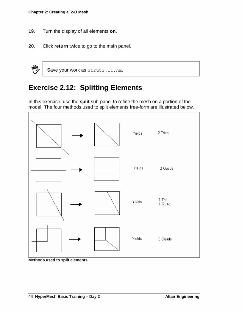
Exercise 2.12: Splitting Elements .......................................................................................44
Exercise 2.13: Checking Normals.......................................................................................46

Table of contents
HyperMesh Basic Training – Day 2 Altair Engineering ii
Chapter 3: Creating a 3-D Mesh.................... ..................................................49
Exercise 3.1: Using the Linear Solid Panel......................................................................... 49
Exercise 3.2: Using the Solid Map Panel............................................................................ 52
Exercise 3.3: Using the Element Offset Panel .................................................................... 53
Exercise 3.4: Checking Element Connectivity .................................................................... 55
Exercise 3.5: Reflecting Elements...................................................................................... 57
Exercise 3.6: Creating Load Collectors .............................................................................. 59
Exercise 3.7: Creating Pressures....................................................................................... 60
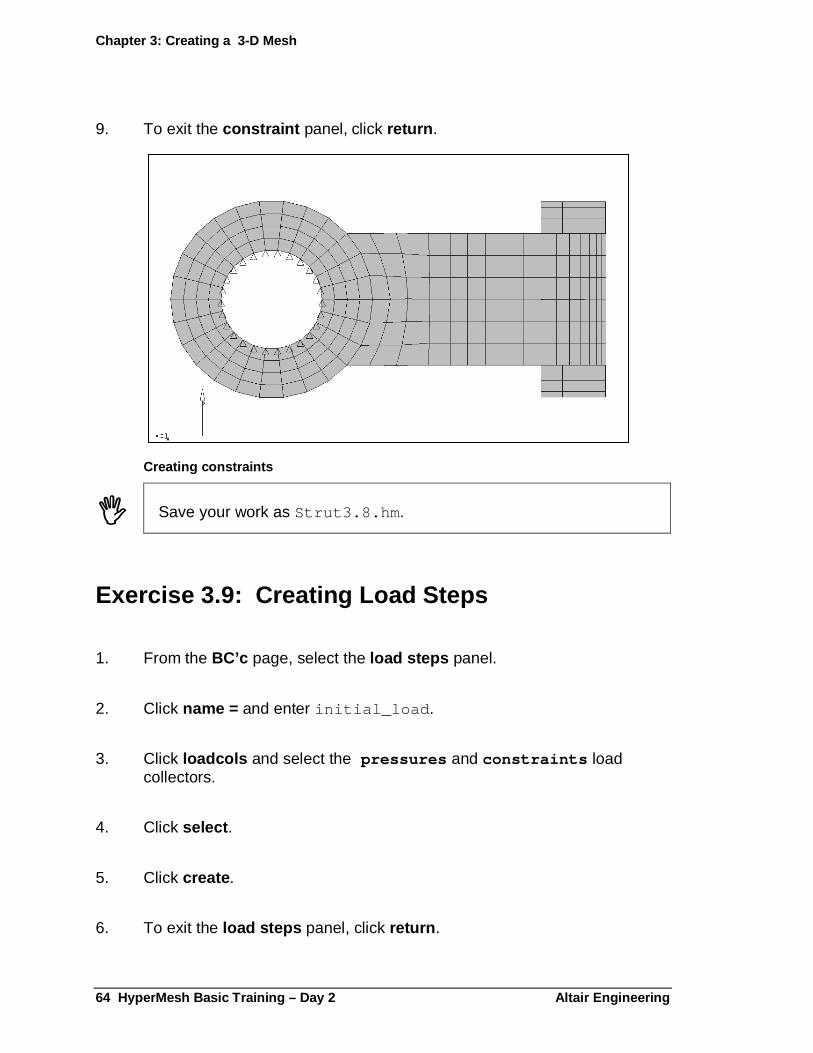
Exercise 3.8: Creating Constraints..................................................................................... 63
Exercise 3.9: Creating Load Steps..................................................................................... 64
Exercise 3.10: Creating an Output Request Control Card................................................... 65
Exercise 3.11: Writing the Analysis Deck ........................................................................... 65
Exercise 3.12: Running the OptiStruct Solver..................................................................... 66
Chapter 4: Post-Processing........................ ....................................................67
Analyzing Results................................... ................................................................................ 67
Exercise 4.1: Using Visualization Tools.............................................................................. 68
Exercise 4.2: Using the Deformed Panel............................................................................ 70
Exercise 4.3: Viewing a Replay File ................................................................................... 72
Exercise 4.4: Viewing the HTML Results Report ................................................................ 73
Chapter 5: Introduction to HyperView............. ..............................................75
The HyperView Screen Display....................... ....................................................................... 76
Exercise 1: Open a session file.......................................................................................... 77
The HyperView Menu................................. ............................................................................. 78
Exercise 2: Playing Animations........................................................................................... 80
Exercise 3: Using View Controls ........................................................................................ 82
Viewing Model Display Characteristics .............. ................................................................... 84
Exercise 4: Clearing the HyperView Session and reading in new files ................................ 84
Exercise 5: Adjusting the viewing attributes........................................................................ 85
Exercise 6: Using the Perspective panel ............................................................................ 88
Chapter 6: Generating H3D files and Post Processing Modal Analysis Results in HyperView ............................... ........................................................91
Exercise 1: Generating H3D files directly from OptiStruct .................................................... 91
Exercise 2: Viewing the HTML Results Report .................................................................... 94

Altair Engineering, Inc Introduction to HyperMesh iii
Exercise 3 : Translating the op2 file using the –h3d option.............................................96
Exercise 4 : Creating a H3D file containing the model information .......................................97
Exercise 5: Clearing the HyperView Session and reading in new files.................................98
Exercise 6: Displaying the Results Contour ........................................................................99
Exercise 7: Reviewing the Deformed Shape.....................................................................104
Exercise 8: Saving the H3D file ........................................................................................106
Exercise 9: Reviewing Multiple Modes..............................................................................109

Table of contents
HyperMesh Basic Training – Day 2 Altair Engineering iv

Altair Engineering HyperMesh Basic Training – Day 2 1
Chapter 1: Automeshing
The automesh panel is used to create a mesh on existing surfaces. There are two modes of meshing available, interactive and automatic . Model display is the same as in the geom cleanup panel, with edges shown according to their connectivity status. For convenience, the cleanup, add or remove points, and proj to edge sub-panels have been included which perform many of the functions found in the geom cleanup panel.
If the interactive method is chosen, after the surface(s) has been selected, the automeshing module is accessed. The sub-panels of the automeshing module include:
density Modifies edge densities
algorithm Selects the mesh and smooth algorithms
type Changes element type from quads to trias or mixed
biasing Applies biasing to the element densities along the surface edges
details Provides fine control over the meshing parameters of a single surface
check Checks element quality with user-specifications
With these panels, the user has a great deal of control over the mesh and resulting element quality.
The mesh params sub-panel, available on the automesh panel, allows you to build meshes using the element size and biasing or using chordal deviation. In order to use mesh parameter settings, you must set the element size = toggle to use mesh params . If the toggle is not set to this option, meshing operations performed in the interactive or automatic sub-panels ignore the settings in the mesh params sub-panel. The right half of the mesh params sub-panel contains options for the tria transition meshing algorithm. The left half contains the settings and options for chordal deviation meshing.
If you set the toggle to use element size and biasing , HyperMesh arranges the nodes that lie on surface edges equidistant from each other and at a spacing approximately equal to the specified element size. If you set the toggle to use chordal deviation , HyperMesh automatically adjusts the surface edge densities and biasing values based on the specified chordal deviation criteria.
Chapter 1: Automeshing
2 HyperMesh Basic Training – Day 2 Altair Engineering
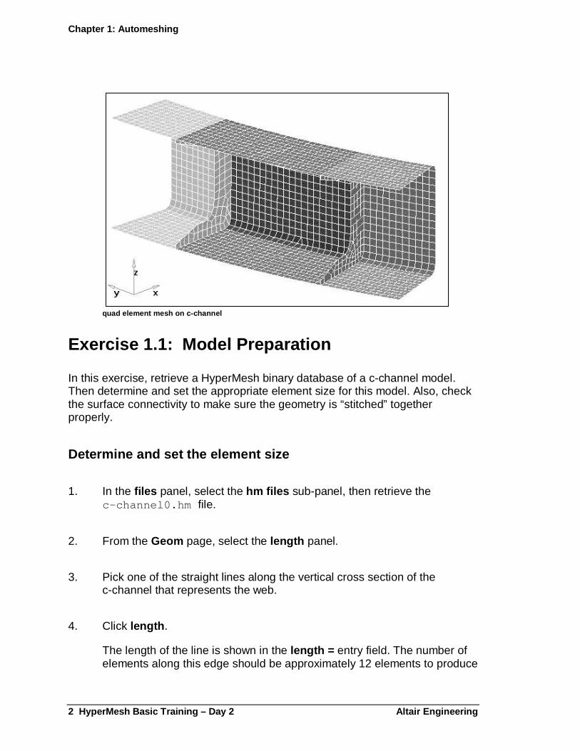
quad element mesh on c-channel
Exercise 1.1: Model Preparation
In this exercise, retrieve a HyperMesh binary database of a c-channel model. Then determine and set the appropriate element size for this model. Also, check the surface connectivity to make sure the geometry is “stitched” together properly.
Determine and set the element size
1. In the files panel, select the hm files sub-panel, then retrieve the c-channel0.hm file.
2. From the Geom page, select the length panel.
3. Pick one of the straight lines along the vertical cross section of the c-channel that represents the web.
4. Click length .
The length of the line is shown in the length = entry field. The number of elements along this edge should be approximately 12 elements to produce

Chapter 1: Automeshing
Altair Engineering HyperMesh Basic Training – Day 2 3
a quality mesh. To compute the element size divide the length by the desired number of elements.
5. Click return to exit the length panel.
6. From the Permanent Menu , select the global panel.
7. Click element size and enter 0.25.
This value is now the default for element size when HyperMesh creates a mesh on a surface. This value can be overridden inside the automesh panel and mesh seeds can be modified in the interactive meshing mode.
8. To exit the global panel, click return .
Checking surface connectivity
1. From the Macro Menu , under Display: gfx click per for performance graphics.
2. From the Macro Menu , under Display: vis opts click option 3 to shade the surfaces and display free, shared, and non-manifold edges.
All the interior edges of the model are either shared or non-manifold edges, as they should be. Therefore, the model is ready for meshing. If free edges appeared in the interior, problems with mesh connectivity could arise after meshing is complete.
3. From the Macro Menu , under Display: vis opts click 0 to return to the wire frame display.
� Save your work as c-channel.ex1 .01.hm .

Chapter 1: Automeshing
4 HyperMesh Basic Training – Day 2 Altair Engineering
Exercise 1.2: Using the Automesh Panel / Interactive Mode
1. From the 2D page, select the automesh panel.
2. Select the create mesh sub-panel.
3. Click surfs and select by collector .
4. Pick the leftend component collector and click select .
5. Activate the option reset meshing parameters to: by clicking in the box.
6. Set the left-upper toggle to elem size .
� In Exercise 1, the default element size was set to 0.25 in the global panel. If desired, the global element size could be over-ridden by changing the value here.
7. Set the lower switch to quads to create 4-noded quad elements.
8. To automatically organize the elements into the surfaces component collector, set the toggle to elements to surface’s comp .
9. To invoke the interactive automeshing mode, set the rightmost toggle to interactive .
10. Click mesh .
This activates the automeshing module. Node positions are indicated along surface edges. Each edge has a value associated with it that tells the number of elements to be created along that edge. These values can be modified as in the next exercise.

Chapter 1: Automeshing
Altair Engineering HyperMesh Basic Training – Day 2 5
Exercise 1.3: Using the Automesh Module / Density Sub-panel
Fitting the meshed surfaces to the screen
1. Click local view .
2. From the pop-up menu select fill .
3. Remove the mouse cursor from the pop-up window to exit local view .
Using the density sub-panel
1. Select the density sub-panel.
2. Click mesh to preview the mesh without adjusting any settings.
3. Click adjust edge to make it the current edge selector.
4. In the graphics area, try changing the edge element densities using the left mouse button and selecting on the edge element density numbers.
A click of the left mouse button increases the density by one and a click of the right mouse button decreases the density by one. A quick way to change the densities by a large amount is to click on the element density number, hold the left mouse button, and drag the mouse up or down. Dragging up increases the element density while similarly dragging down decreases it.
5. After modifying the edge element densities, click mesh to preview your changes.
6. Click element size = and enter 0.5 .
7. Click recalc edge to make it the current edge selector.

Chapter 1: Automeshing
6 HyperMesh Basic Training – Day 2 Altair Engineering
8. In the graphics area, click on one of the element density values.
This recalculates the element edge density for the selected edge to an element size of 0.5 (rounded to the nearest whole number).
9. After modifying the edge element densities, click mesh to preview your changes.
10. Click recalc all to set all the edges to element size 0.5 .
11. Click mesh to preview your changes.
12. Click element density = and enter 10 .
13. To make it the current edge selector, click set edge to .
14. In the graphics area, try changing the edge element densities using the left mouse button and selecting on the edge element density numbers.
This sets the element edge density for each edge selected to a value of 10.
15. After modifying the edge element densities, click mesh to preview your changes.
16. Set all the edges to an element density of 10 by clicking set all to .
17. To preview your changes, click mesh .
Obtain the finished mesh
1. Click element size and enter 0.25 .
2. To set all the edges to element size 0.25, click recalc all .
3. To preview your changes, click mesh .
Chapter 1: Automeshing
Altair Engineering HyperMesh Basic Training – Day 2 7
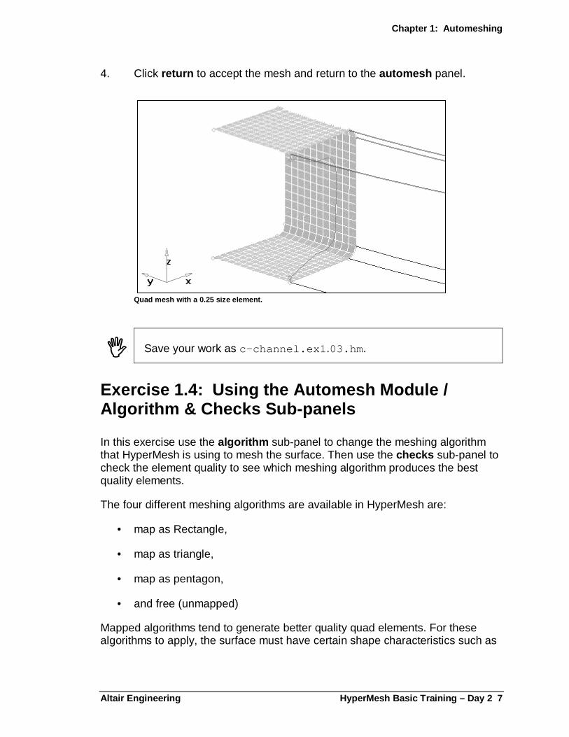
4. Click return to accept the mesh and return to the automesh panel.
Quad mesh with a 0.25 size element.
� Save your work as c-channel.ex1 .03.hm .
Exercise 1.4: Using the Automesh Module / Algorithm & Checks Sub-panels
In this exercise use the algorithm sub-panel to change the meshing algorithm that HyperMesh is using to mesh the surface. Then use the checks sub-panel to check the element quality to see which meshing algorithm produces the best quality elements.
The four different meshing algorithms are available in HyperMesh are:
• map as Rectangle,
• map as triangle,
• map as pentagon,
• and free (unmapped)
Mapped algorithms tend to generate better quality quad elements. For these algorithms to apply, the surface must have certain shape characteristics such as

Chapter 1: Automeshing
8 HyperMesh Basic Training – Day 2 Altair Engineering
rectangular, triangular or pentagonal. The free (unmapped) algorithm will mesh most any surface regardless of shape.
Using the algorithm sub-panel
1. In the disp panel, turn off the elements in the leftend collector.
2. In the automesh panel, click surfs and select by collector .
3. Pick the rib1 component collector and click select .
4. To invoke the automeshing module, click mesh .
5. To fit the meshed area to the screen, click, next to local view , f.
6. Select the algorithm sub-panel.
� The blue icon appearing on the surface identifies the meshing algorithm used to mesh the surface. If you choose multiple surfaces, an icon would appear on each surface. By default, HyperMesh chooses the algorithm based upon the selected surface’s geometry (in this case free (unmapped)).
Chapter 1: Automeshing
Altair Engineering HyperMesh Basic Training – Day 2 9
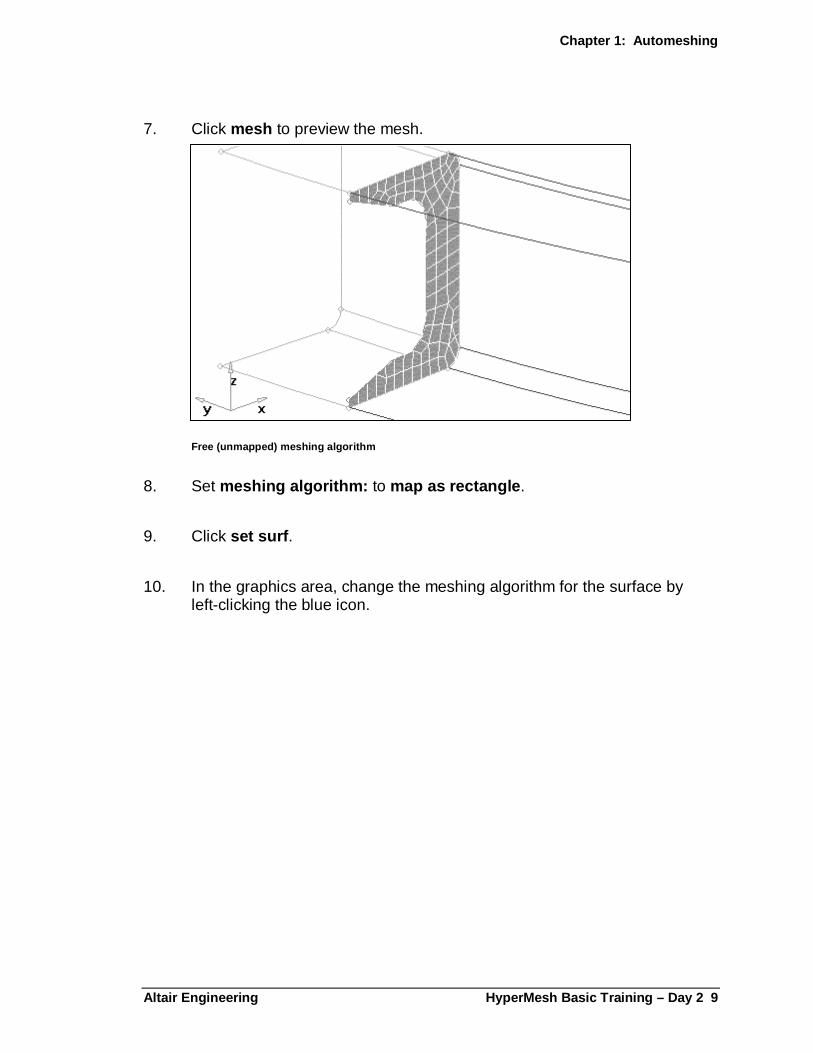
7. Click mesh to preview the mesh.
Free (unmapped) meshing algorithm
8. Set meshing algorithm: to map as rectangle .
9. Click set surf .
10. In the graphics area, change the meshing algorithm for the surface by left-clicking the blue icon.
Chapter 1: Automeshing
10 HyperMesh Basic Training – Day 2 Altair Engine ering
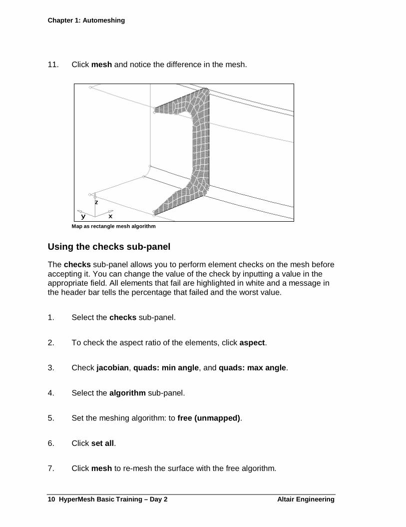
11. Click mesh and notice the difference in the mesh.
Map as rectangle mesh algorithm
Using the checks sub-panel
The checks sub-panel allows you to perform element checks on the mesh before accepting it. You can change the value of the check by inputting a value in the appropriate field. All elements that fail are highlighted in white and a message in the header bar tells the percentage that failed and the worst value.
1. Select the checks sub-panel.
2. To check the aspect ratio of the elements, click aspect .
3. Check jacobian , quads: min angle , and quads: max angle .
4. Select the algorithm sub-panel.
5. Set the meshing algorithm: to free (unmapped) .
6. Click set all .
7. Click mesh to re-mesh the surface with the free algorithm.

Chapter 1: Automeshing
Altair Engineering HyperMesh Basic Training – Day 2 11
8. Repeat steps 1 through 3 and notice the difference in element quality.
9. Click return to accept the mesh and return to the automesh panel.
� Save your work as c-channel.ex1 .04.hm .
Exercise 1.5: Using the Automesh Module/Type and Biasing Sub-panel
In this exercise use the type sub-panel to change the element configuration from quad to tria to mixed. Then use the biasing sub-panel to modify the node spacing along the surface edges.
Using the type sub-panel
1. In the display panel, turn off the elements in the rib1 collector.
2. In the automesh panel, click surfs and select by collector .
3. Pick rib2, middle, and rightend component collector and click select .
4. Click mesh to invoke the automeshing module.
5. Next to local view , click f to fit the meshed area.
6. To preview the mesh, click mesh .
7. Select the type sub-panel.
Similar to the algorithm sub-panel, a blue icon appears on each surface identifying the mesh type used to mesh the surface. Since the setting on the automesh panel was quads, all surfaces have a quad icon.
8. Set the element type: to trias .
9. Click set surf .
Chapter 1: Automeshing
12 HyperMesh Basic Training – Day 2 Altair Engine ering
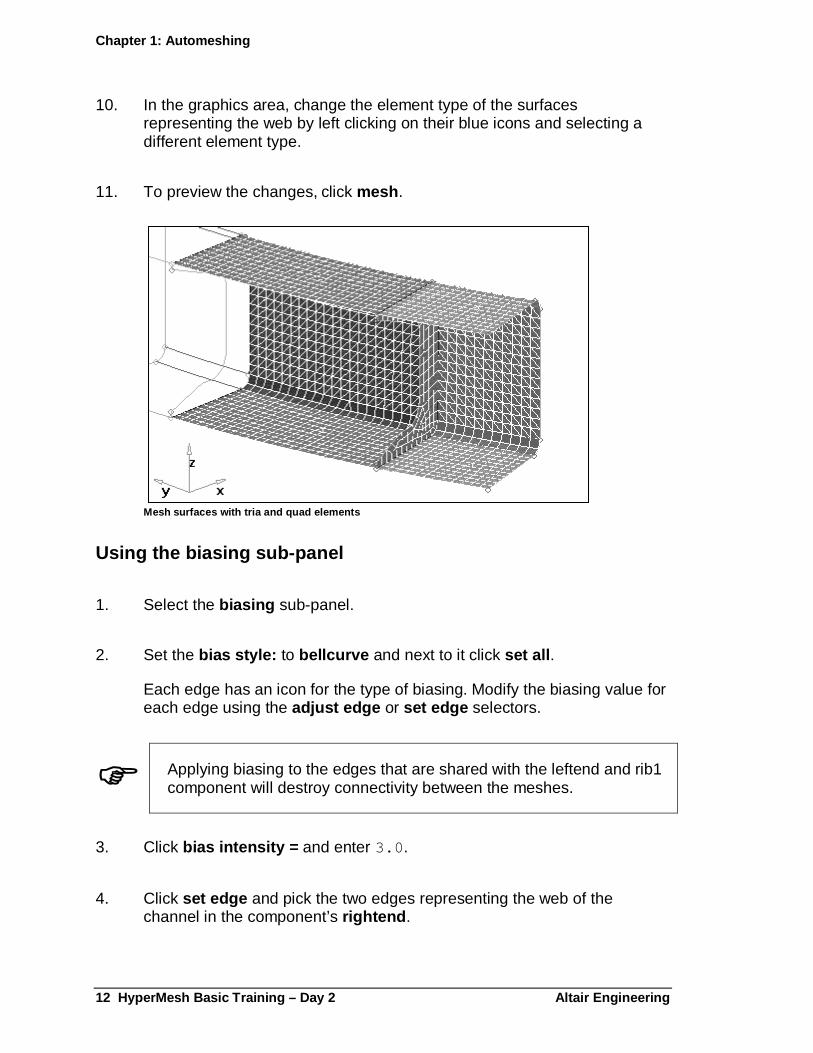
10. In the graphics area, change the element type of the surfaces representing the web by left clicking on their blue icons and selecting a different element type.
11. To preview the changes, click mesh .
Mesh surfaces with tria and quad elements
Using the biasing sub-panel
1. Select the biasing sub-panel.
2. Set the bias style: to bellcurve and next to it click set all .
Each edge has an icon for the type of biasing. Modify the biasing value for each edge using the adjust edge or set edge selectors.
� Applying biasing to the edges that are shared with the leftend and rib1 component will destroy connectivity between the meshes.
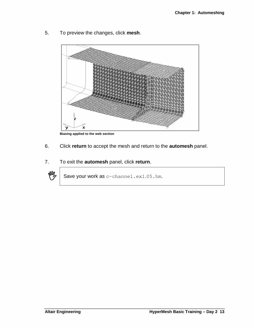
3. Click bias intensity = and enter 3.0 .
4. Click set edge and pick the two edges representing the web of the channel in the component’s rightend .
Chapter 1: Automeshing
Altair Engineering HyperMesh Basic Training – Day 2 13
5. To preview the changes, click mesh .
Biasing applied to the web section
6. Click return to accept the mesh and return to the automesh panel.
7. To exit the automesh panel, click return .
� Save your work as c-channel.ex1 .05.hm .
Chapter 1: Automeshing
14 HyperMesh Basic Training – Day 2 Altair Engine ering
Exercise 1.6: Equivalencing Nodes
In this exercise, to ensure connectivity between the elements you will equivalence any coincident nodes in the model. The equivalencing operation identifies any location where two or more nodes exist within the specified search tolerance. During equivalencing, one of the nodes will be retained, and the remaining nodes are redefined to use the retained node’s element definitions.
1. From the Macro Menu , under Display: elems click on . Then refit the model to the screen.
2. From the Tool page, select the edges panel.
3. Set the switch to comps and select all the component collectors.
4. Set the tolerance to 0.010 and click preview equiv .
Even though all the geometry was “stitched” together, performing the automeshing operations in different steps does not ensure the resulting elements will have shared nodes. However, when surfaces are meshed in a single automeshing procedure, such as those in rib2, middle and rightend, all the nodes are shared at the surface boundaries, ensuring connectivity.
5. To stitch the model together, click equivalence .
6. To exit the edges panel, click return .
� Save your work as c-channel.ex1 .06.hm .

Chapter 1: Automeshing
Altair Engineering HyperMesh Basic Training – Day 2 15
Exercise 1.7: Using chordal deviation
Chordal deviation is often used for metalforming analyses where large concentrations of elements are required at areas of high curvature. To read more about chordal deviation meshing, refer to the on-line help.
Deleting the elements
1. Press F2 on the keyboard to access the delete panel.
2. Set the switch to elems .
3. Click elems and select all .
4. Click delete entity .
5. To exit the delete panel, click return .
Creating the mesh using chordal deviation
1. From the 2D page, select the automesh panel.
2. Select the mesh params sub-panel.
3. Set the toggle to use chordal deviation .
4. Click min elem size = and enter 0.15 .
5. Click max elem size and enter 0.80 .
6. Click max deviation and enter 0.10 .
7. Click max angle = and enter 20.0 .
Chapter 1: Automeshing
16 HyperMesh Basic Training – Day 2 Altair Engine ering
8. Select the create mesh sub-panel.
9. Click surfs and select by collector .
10. Pick the leftend component collector and click select .
11. Click the reset mesh parameters option.
12. Set the left-upper toggle to use mesh params .
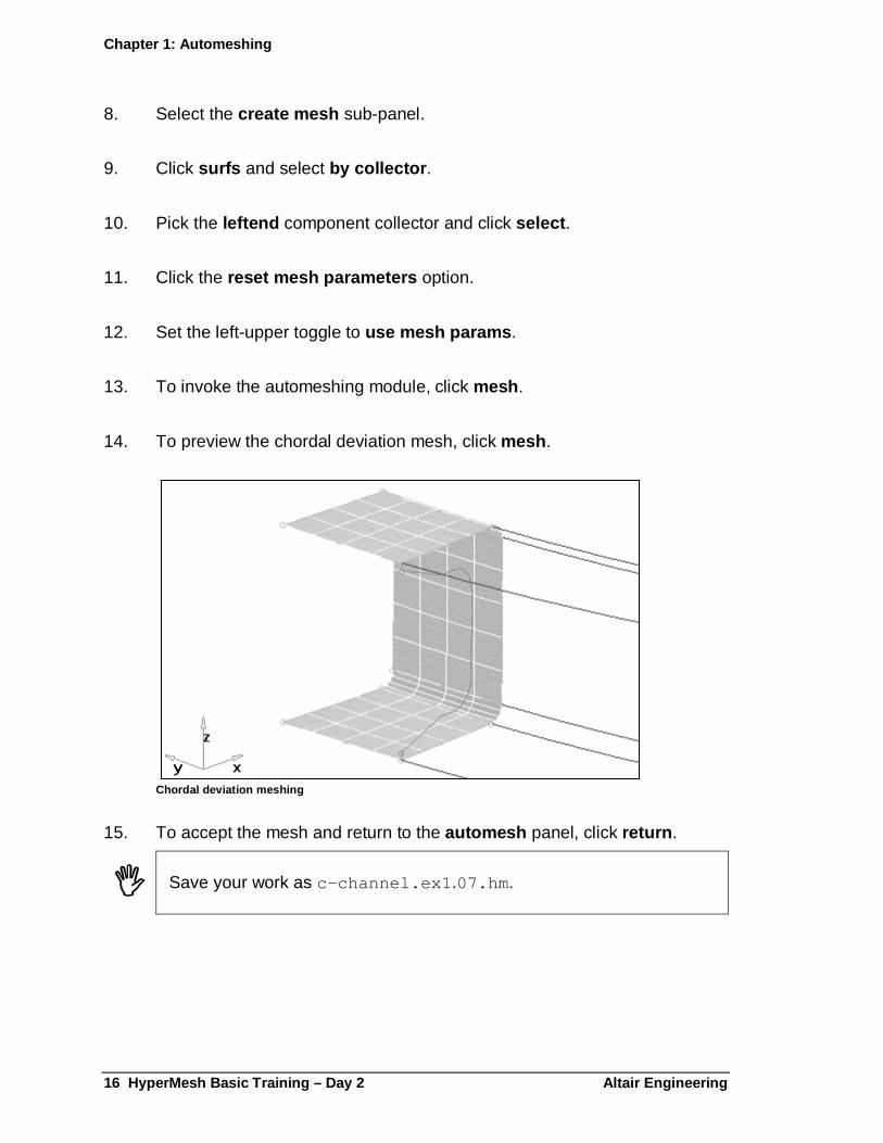
13. To invoke the automeshing module, click mesh .
14. To preview the chordal deviation mesh, click mesh .
Chordal deviation meshing
15. To accept the mesh and return to the automesh panel, click return .
� Save your work as c-channel.ex1 .07.hm .

Chapter 1: Automeshing
Altair Engineering HyperMesh Basic Training – Day 2 17
Exercise 1.8: Understanding mesh parameters
In this section, check the mesh parameters of a surface and learn how to reset them.
Meshing without resetting the surface mesh paramete rs
1. In the automesh panel, select the create mesh sub-panel.
2. Click surfs and select by collector .
3. Pick the middle and rightend component collectors and click select .
4. Deactivate the reset meshing parameters to: option.
5. Set the left-uppermost toggle to elem size = .
6. Click elem size = and enter 0.5 .
7. Set the lower switch to trias .
8. To invoke the automeshing module, click mesh .
9. To preview the mesh, click mesh .
Notice the mesh matches the one previously deleted for these surfaces since HyperMesh saves the meshing parameters for each surface and edge it has meshed.
The mesh seeding you see on the surface edge between the left end and the middle component reflects the original meshing of the left end. HyperMesh does this to maintain element connectivity for shared edges. When you want to alter the mesh seeding, check the reset mesh parameters option to recalculate the node placement based on the parameters specified.

Chapter 1: Automeshing
18 HyperMesh Basic Training – Day 2 Altair Engine ering
Using the details sub-panel to query surface mesh p arameters
1. Select the details sub-panel.
2. Click the icon in the center of the surface that represents the web of the channel in the right end component collector.
This changes the options in the menu panel to match the mesh parameter settings for that surface. It shows the element densities in the graphics area and updates the element type and algorithm in the menu area. To confirm this, we will check the bias settings next.
3. Set the toggle to biases and confirm that the biasing is 3.0 along the web as set in Exercise 1.5.
4. To exit the automesh module and return to the automesh panel without keeping the mesh, click abort .
Meshing and resetting the surface mesh parameters
1. Select the surfaces in the middle and rightend components
2. Reactivate the option reset meshing parameters to: .
3. To invoke the automeshing module, click mesh .

Chapter 1: Automeshing
Altair Engineering HyperMesh Basic Training – Day 2 19
4. To preview the mesh, click mesh .
Notice all the mesh parameters for the surfaces and edges are reset to reflect the element size of 0.5 and mapped with tria elements.
Tria mesh with density of 0.5.
5. To accept the mesh and return to the automesh panel, click return .
� Save your work as c-channel.ex1 .08.hm .
Exercise 1.9: Using the Automesh Panel / Automatic Mode
1. In the automesh panel, select the create mesh sub-panel.
2. Click surfs and select by collector .
3. Pick the rib1 and rib2 component collectors and click select .
4. Set the rightmost toggle to automatic .
Chapter 1: Automeshing
20 HyperMesh Basic Training – Day 2 Altair Engine ering
5. Click mesh to automatically mesh the surfaces.
Automatic mesh of the ribs
� Save your work as c-channel.ex1 .09.hm .
Exercise 1.10: Remeshing surfaces
In this exercise, re-mesh all of the surfaces. Use remesh to delete all the elements associated to the surfaces then re-mesh the model.
1. In the automesh panel, select the create mesh sub-panel.
2. Click surfs and select all .
3. Activate the option reset meshing parameters to: .
4. Set the left-upper toggle to elem size = .
5. Click elem size = and enter 0.25 .
Chapter 1: Automeshing
Altair Engineering HyperMesh Basic Training – Day 2 21
6. Set the lower switch to quads .
7. Set the rightmost toggle to automatic .
8. Click remesh .
Quad mesh
9. Click return to exit the automesh panel.
� Save your work as c-channel.ex1 .10.hm .

Chapter 1: Automeshing
22 HyperMesh Basic Training – Day 2 Altair Engine ering
Altair Engineering HyperMesh Basic Training – Day 2 23
Chapter 2: Creating a 2-D Mesh
In this section, create a finite element model of a strut by using the 2-D element creation panels.
Strut model
Exercise 2.1: Importing IGES Data
Importing the iges geometry data and specify the te mplate
1. From the files panel, select the import sub-panel.
2. Click the selector next to GEOM and select iges from the pop-up menu.

Chapter 2: Creating a 2-D Mesh
24 HyperMesh Basic Training – Day 2 Altair Enginee ring
3. Click the green import… button to bring up the file browser.
4. Locate the strut.iges file in your working directory, then click Open on the file browser to read the file into HyperMesh..
5. Select the template sub-panel
6. Click the green load… button to bring up the file browser. Select the optistruct directory and subsequently, the optistruct template file.
Selecting the OptiStruct template allows you to define OptiStruct specific attributes in your HyperMesh session.
7. To exit the files panel, click return .
8. From the Permanent Menu , go to the global panel.
9. Set the global element size to 15 .
10. Click return to exit the global panel
� Save your work as Strut2.01.hm .
Exercise 2.2: Setting up Material Properties
The material type of this model is steel. In this exercise, create a material collector.
1. Select the collectors panel.
2. Select the create sub-panel.
3. Set the collectors type to mats .
4. Click name = and enter steel .
Chapter 2: Creating a 2-D Mesh
Altair Engineering HyperMesh Basic Training – Day 2 25
5. Set creation method: to card image .
6. Click card image = and select MAT1.
7. Click create/edit .
8. Click E, click the data entry field, and enter 2.0e5 .
9. Click NU, click the data entry field, and enter 0.30 .
10. Click return .
� Save your work as Strut2.02.hm .
Exercise 2.3: Creating Component Collectors
To simplify the model building process, the strut model will be split into three sections, endA, the arm, and endB. In this exercise, three component collectors will be created to store 2d shell elements in endA, the arm, and endB and three more to store 3d solid elements in endA, the arm, and endB.
Creating the 2d shell element component collector f or endA
1. Set the collector type: to comps .
2. Click name = and enter 2D_endA.
3. Set creation method: to no card image .
The shell elements that will be built in this chapter will only be used for creating the 3d solid element mesh and will not be used for the analysis. Therefore, it is not necessary to assign these elements the OptiStruct card image and we can use the no card image option.
4. Click material = and select steel.
5. Click color and select a color from the pop-up menu.
Chapter 2: Creating a 2-D Mesh
26 HyperMesh Basic Training – Day 2 Altair Enginee ring
6. To create the component, click create .
Creating the 2d shell element component collector f or the arm
1. Click name = and enter 2D_arm.
2. Set the creation method: to no card image .
3. Click color and select a color from the pop-up menu.
4. Click create to create the component collector.
Creating the 2d shell element component collector f or endB
1. Click name = and enter 2D_endB.
2. Set the creation method: to no card image .
3. Click color and select a color from the pop-up menu.
4. To create the component collector, click create .
Creating the 3d solid element component collector f or endA
1. Click name = and enter 3D_endA.
2. Set creation method: to card image = .
3. Click card image = and select PSOLID.
4. Click material = and select steel.
5. Click color and select a color from the pop-up menu.

Chapter 2: Creating a 2-D Mesh
Altair Engineering HyperMesh Basic Training – Day 2 27
6. Click create .
� None of the fields on the OptiStruct PSOLID card can be edited, so there is no need to use the create/edit option when creating this collector.
Creating the 3d solid element component collector f or the arm
1. Click name = and enter 3D_arm.
2. Set the creation method: to same as .
This same as option allows the next component collector that you create to have the same card image as a previously defined component collector.
3. Click same as = and select 3D_endA.
4. Click color and select a color from the pop-up menu.
5. Click create .
Creating the 3d solid element component collector f or endB
1. Click name = and enter 3D_endB.
2. Set the creation method: to same as .
3. Click same as = and select 3D_endA .
4. Click color and select a color from the pop-up menu.
5. Click create .
6. To exit the collectors panel, click return .
� Save your work as strut.2.03.hm .
Chapter 2: Creating a 2-D Mesh
28 HyperMesh Basic Training – Day 2 Altair Enginee ring
2-D Modeling The following exercises show how to use several of the 2-D meshing panels. First use the geometry editing panels to prepare the model for meshing. Then use the spin , ruled , skin and spline panels to create shell elements. Last, check and edit the elements before proceeding to the 3-D meshing exercises.
Exercise 2.4: Editing Geometry
In this exercise, trim a line with another line by using the line edit panel.
1. From the Geom page, select the line edit panel.
2. Select the split at joint sub-panel.
3. The lines selector is active. Pick the straight line at the ends of the arcs at end A as the line to be split.
Once the line is selected, three vertices are identified as possible joints where the line may be split. Pick the joint in the most negative Y position to split the line at that point. See the image below.
Once the vertex is specified, the line is split.
Set up for splitting the line
Select this vertex as the point to split the line
Chapter 2: Creating a 2-D Mesh
Altair Engineering HyperMesh Basic Training – Day 2 29
4. Click return to exit the line edit panel.
� Save your work as Strut2.04.hm .
Exercise 2.5: Trimming A Surface
1. From the Geom page, select the surface edit panel.
2. Select the trim with line sub-panel.
3. Pick the surface to be trimmed.
Selecting the surface to trim
4. Click lines and pick the trim line.
5. Set sweep trim line to normal to surface .
6. Click tolerance = and enter 0.100 .
Chapter 2: Creating a 2-D Mesh
30 HyperMesh Basic Training – Day 2 Altair Enginee ring
7. Click trim .
8. Click return to exit the surface edit panel.
Deleting the surface
1. From the Tool page, select the delete panel or press F2 on the keyboard.
2. Set the entity selector to surfs .
3. Pick the small surface.
4. Click delete entity .
5. To exit the delete panel, click return .
Resulting model
� Save your work as Strut2.05.hm .

Chapter 2: Creating a 2-D Mesh
Altair Engineering HyperMesh Basic Training – Day 2 31
Exercise 2.6: Using the Spin Panel
1. From the global panel, click component = and select 2D_endA and return .
2. From the 2D page, select the spin panel.
3. Select the spin geoms sub-panel.
4. Set the entity selector to line list .
5. Pick the shorter line across the end of the arc (be sure line list is highlighted).
6. Set the direction selector to x axis to define the global yz plane.
7. Press F4 to access the distance panel.
8. Select the two nodes sub-panel.
9. Pick the nodes at the ends of the large half circle as N1 and N2.
In the graphics window, click and hold down the left mouse button until a square appears. Drag the square over the line on which you’d like to create a node. When the line highlights, release the mouse button. The line remains highlighted. Left click anywhere on the highlighted line to create a node.
10. Click nodes between = and enter 1.
11. Click nodes between .
12. Click return to exit the distance panel and return to the spin panel.
13. Pick the temp node at the center of the arc as the base node .
Chapter 2: Creating a 2-D Mesh
32 HyperMesh Basic Training – Day 2 Altair Enginee ring
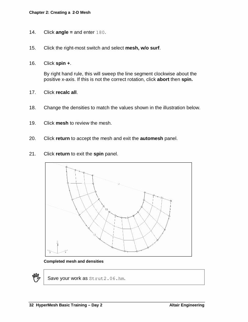
14. Click angle = and enter 180 .
15. Click the right-most switch and select mesh, w/o surf .
16. Click spin + .
By right hand rule, this will sweep the line segment clockwise about the positive x-axis. If this is not the correct rotation, click abort then spin.
17. Click recalc all .
18. Change the densities to match the values shown in the illustration below.
19. Click mesh to review the mesh.
20. Click return to accept the mesh and exit the automesh panel.
21. Click return to exit the spin panel.
Completed mesh and densities
� Save your work as Strut2.06.hm .

Chapter 2: Creating a 2-D Mesh
Altair Engineering HyperMesh Basic Training – Day 2 33
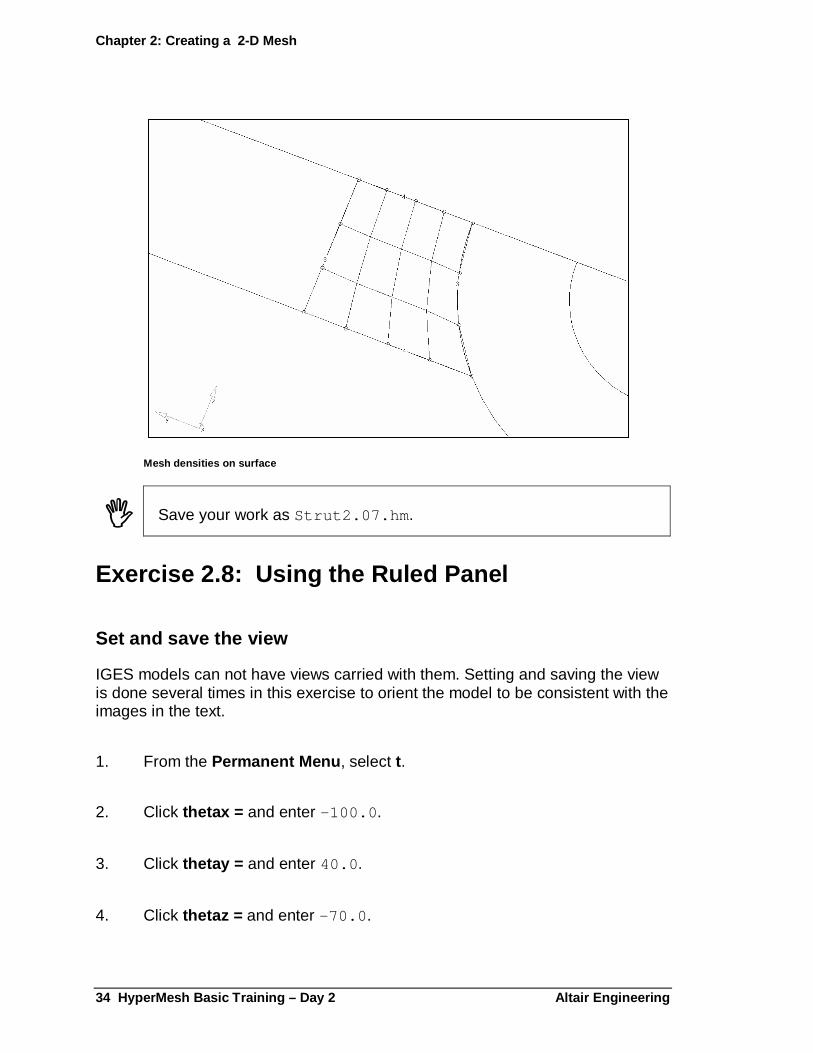
Exercise 2.7: Meshing a Surface
1. From the global panel, click component = and select 2D_arm and return .
2. From the 2D page, select the automesh panel.
3. Select the create mesh sub-panel.
4. Set the meshing method to interactive .
5. Set the entity selector to surfs .
6. Pick the surface to the right of End A.
7. Activate the reset meshing parameters to option.
8. Click elem size = and enter 15 .
9. Set the element type to quads .
10. Select elements to current component .
11. Click mesh .
12. Change the densities to match those in the illustration.
13. Click mesh to review the elements.
14. Click return to accept the mesh.
15. Click return to exit the automesh panel.
Chapter 2: Creating a 2-D Mesh
34 HyperMesh Basic Training – Day 2 Altair Enginee ring
Mesh densities on surface
� Save your work as Strut2.07.hm .
Exercise 2.8: Using the Ruled Panel
Set and save the view
IGES models can not have views carried with them. Setting and saving the view is done several times in this exercise to orient the model to be consistent with the images in the text.
1. From the Permanent Menu , select t.
2. Click thetax = and enter –100.0 .
3. Click thetay = and enter 40.0 .
4. Click thetaz = and enter –70.0 .

Chapter 2: Creating a 2-D Mesh
Altair Engineering HyperMesh Basic Training – Day 2 35
5. Click set angles .
6. Click return to exit the true view panel.
7. From the Permanent Menu , select view .
8. Click save 1 = .
The current position and orientation of the model is saved as view1.
9. Move the mouse outside the borders of the pop-up menu.
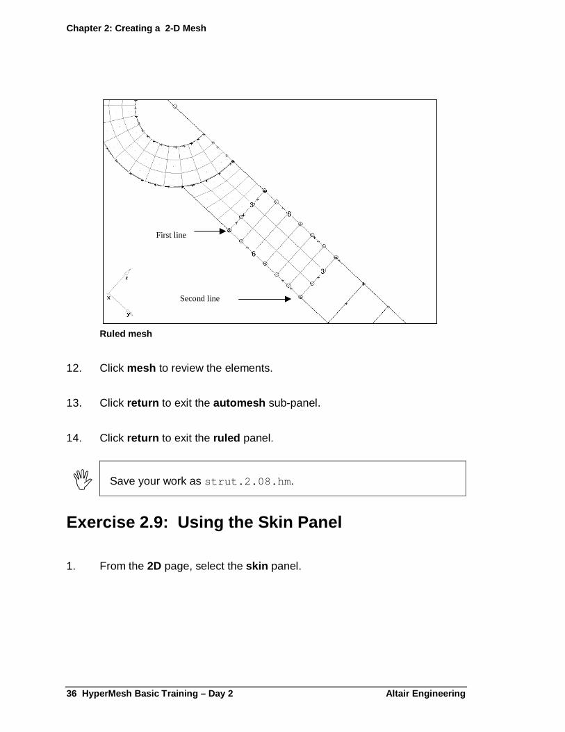
Creating a ruled mesh
1. From the 2D page, select the ruled panel.
2. Set the upper entity collector type to line list .
3. Pick the line bordering the existing surface mesh.
4. Set the lower entity collector type to line list .
5. Pick the next line on the arm.
6. Select mesh, w/o surf .
7. Activate the auto reverse option.
8. Click create .
9. Click element size = and enter 15.0 .
10. Click recall all .
11. Change the densities to match those in the illustration.
Chapter 2: Creating a 2-D Mesh
36 HyperMesh Basic Training – Day 2 Altair Enginee ring
Ruled mesh
12. Click mesh to review the elements.
13. Click return to exit the automesh sub-panel.
14. Click return to exit the ruled panel.
� Save your work as strut.2.08.hm .
Exercise 2.9: Using the Skin Panel
1. From the 2D page, select the skin panel.
First line
Second line
Chapter 2: Creating a 2-D Mesh
Altair Engineering HyperMesh Basic Training – Day 2 37
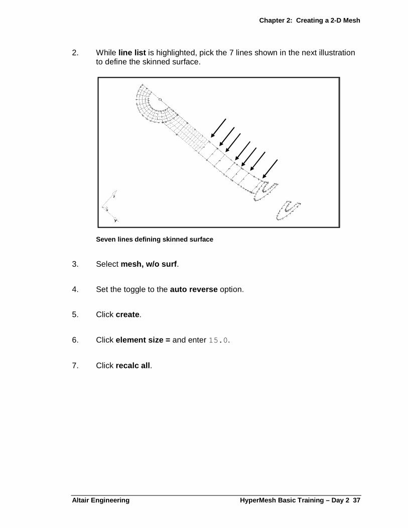
2. While line list is highlighted, pick the 7 lines shown in the next illustration to define the skinned surface.
Seven lines defining skinned surface
3. Select mesh, w/o surf .
4. Set the toggle to the auto reverse option.
5. Click create .
6. Click element size = and enter 15.0 .
7. Click recalc all .
Chapter 2: Creating a 2-D Mesh
38 HyperMesh Basic Training – Day 2 Altair Enginee ring
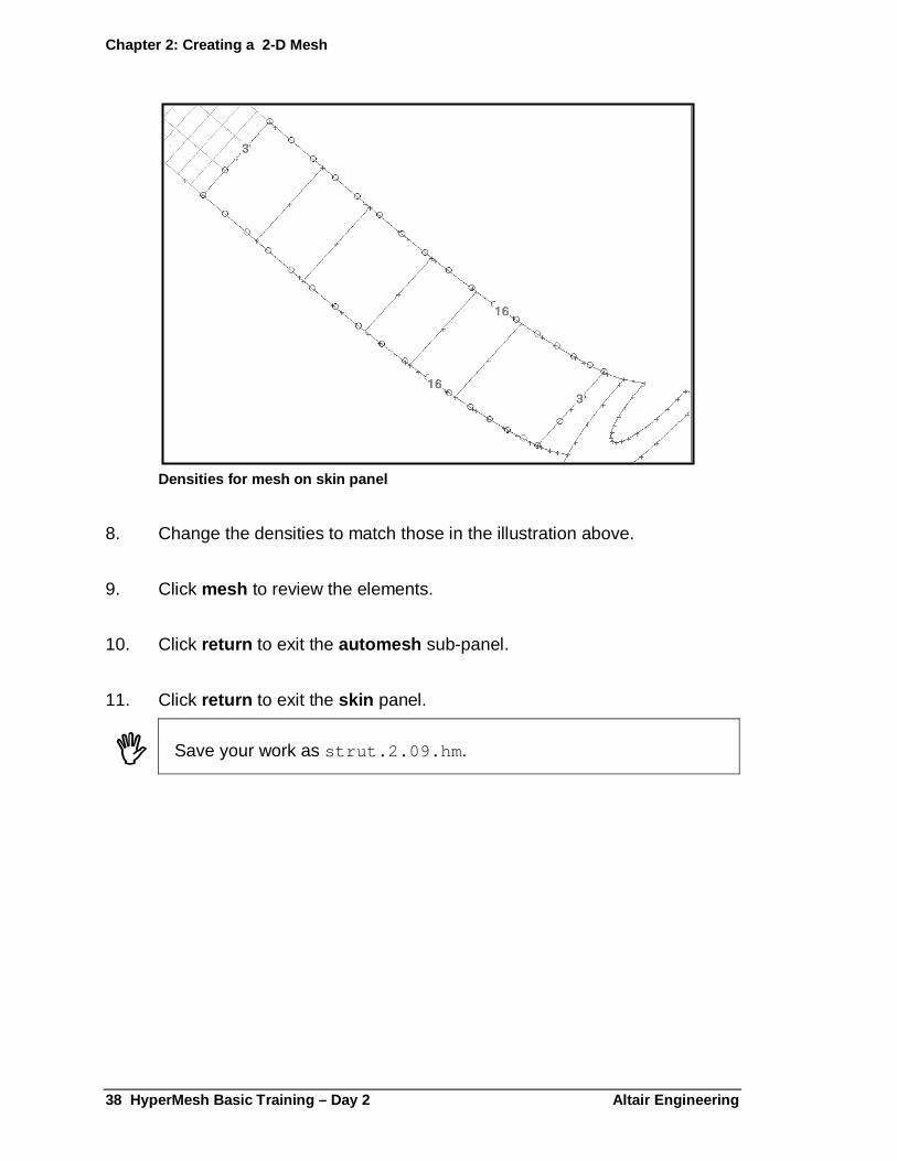
Densities for mesh on skin panel
8. Change the densities to match those in the illustration above.
9. Click mesh to review the elements.
10. Click return to exit the automesh sub-panel.
11. Click return to exit the skin panel.
� Save your work as strut.2.09.hm .

Chapter 2: Creating a 2-D Mesh
Altair Engineering HyperMesh Basic Training – Day 2 39
Exercise 2.10: Using the Spline Panel
In this exercise, use the spline panel to create a mesh. The spline function will create a surface and/or mesh from any area enclosed by a series of lines.
Setting the view and saving it
1. From the Permanent Menu , select t.
2. Click thetax = and enter –80 .
3. Click thetay = and enter 0.
4. Click thetaz = and enter –10 .
5. Click set angles .
6. Click return to exit the true view panel.
7. From the Permanent Menu , select view .
8. Click save 2 = .
9. Move the mouse outside the borders of the pop-up menu.
Creating the mesh
1. From the 2D page, select the spline panel.
2. With lines as the entity type, select the four lines bounding the remaining unmeshed region of the arm.
Even though the lines extend beyond the region that we wish to mesh, only the area enclosed by the lines will be used in the meshing operation. There is no need to trim the lines prior to meshing.
Chapter 2: Creating a 2-D Mesh
40 HyperMesh Basic Training – Day 2 Altair Enginee ring
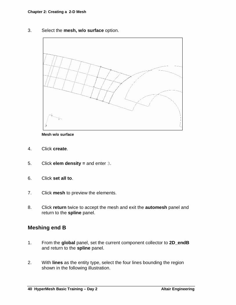
3. Select the mesh, w/o surface option.
Mesh w/o surface
4. Click create .
5. Click elem density = and enter 3.
6. Click set all to .
7. Click mesh to preview the elements.
8. Click return twice to accept the mesh and exit the automesh panel and return to the spline panel.
Meshing end B
1. From the global panel, set the current component collector to 2D_endB and return to the spline panel.
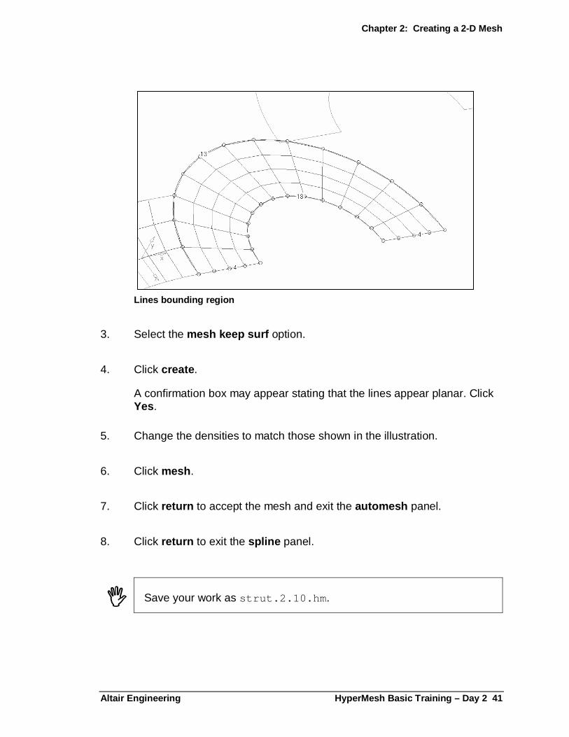
2. With lines as the entity type, select the four lines bounding the region shown in the following illustration.
Chapter 2: Creating a 2-D Mesh
Altair Engineering HyperMesh Basic Training – Day 2 41
Lines bounding region
3. Select the mesh keep surf option.
4. Click create .
A confirmation box may appear stating that the lines appear planar. Click Yes.
5. Change the densities to match those shown in the illustration.
6. Click mesh .
7. Click return to accept the mesh and exit the automesh panel.
8. Click return to exit the spline panel.
� Save your work as strut.2.10.hm .

Chapter 2: Creating a 2-D Mesh
42 HyperMesh Basic Training – Day 2 Altair Enginee ring
Exercise 2.11: Checking Elements and Models
In this exercise, check the quality and connectivity of the shell elements.
Checking the Jacobian of the shell elements
1. From the Permanent Menu , select the view panel and click restore1 .
2. From the Tool page, select the check elems panel.
3. Select the 2-D sub-panel.
4. Select the assign plot option.
5. Click jacobian .
A contour plot of the element Jacobian value displays. The color of the element corresponds to the value. Change the default threshold for failure, 0.7, by clicking in the number field and entering a new value.
6. Click return .
7. From the Tool page, select the edges panel.
8. Click comps and select 2D_endA , 2D_arm , and 2D_endB from the list of component collectors.
9. Click select .
10. Click find edges .
11. From the Macro Menu , click the geom off button to turn off the display of the geometry.
12. From the Permanent Menu , select the display panel.
Chapter 2: Creating a 2-D Mesh
Altair Engineering HyperMesh Basic Training – Day 2 43
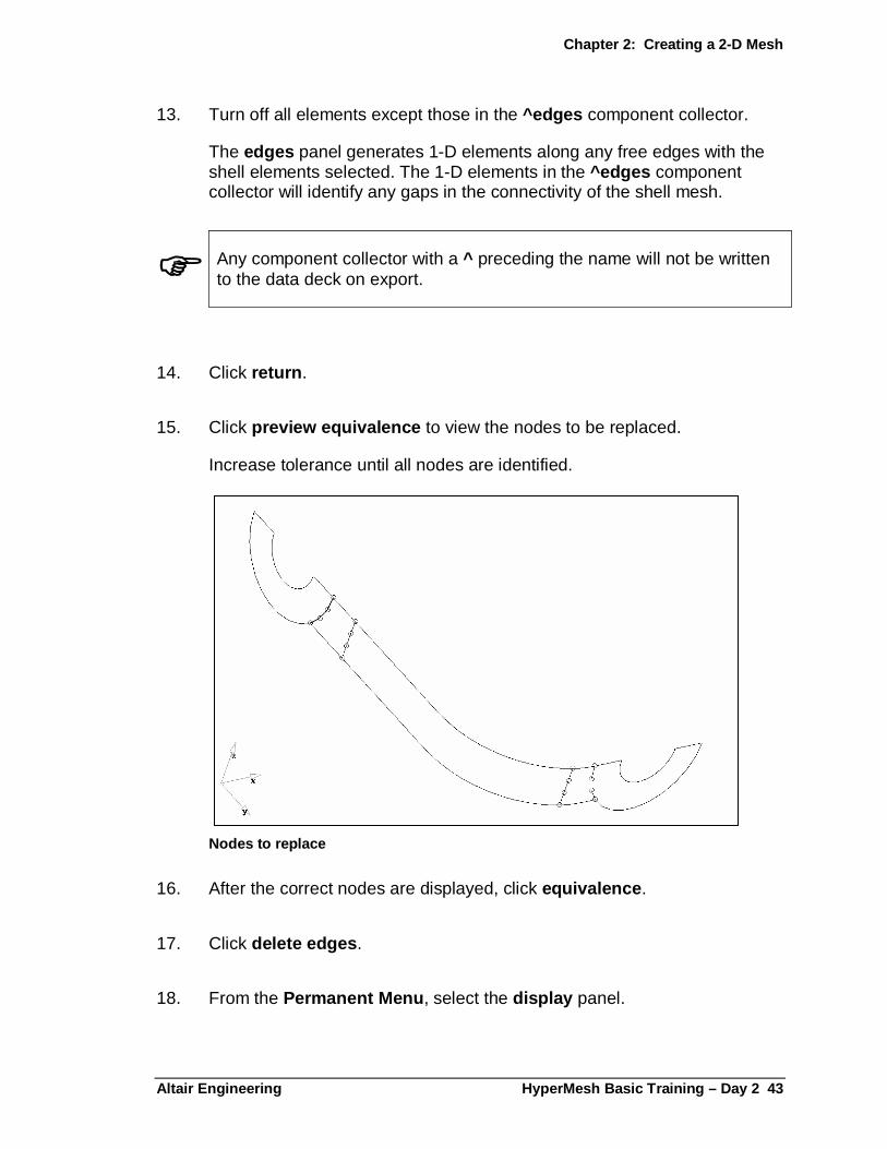
13. Turn off all elements except those in the ^edges component collector.
The edges panel generates 1-D elements along any free edges with the shell elements selected. The 1-D elements in the ^edges component collector will identify any gaps in the connectivity of the shell mesh.
� Any component collector with a ^ preceding the name will not be written to the data deck on export.
14. Click return .
15. Click preview equivalence to view the nodes to be replaced.
Increase tolerance until all nodes are identified.
Nodes to replace
16. After the correct nodes are displayed, click equivalence .
17. Click delete edges .
18. From the Permanent Menu , select the display panel.
Chapter 2: Creating a 2-D Mesh
44 HyperMesh Basic Training – Day 2 Altair Enginee ring
19. Turn the display of all elements on .
20. Click return twice to go to the main panel.
� Save your work as Strut2.11.hm .
Exercise 2.12: Splitting Elements
In this exercise, use the split sub-panel to refine the mesh on a portion of the model. The four methods used to split elements free-form are illustrated below.
Methods used to split elements
Chapter 2: Creating a 2-D Mesh
Altair Engineering HyperMesh Basic Training – Day 2 45
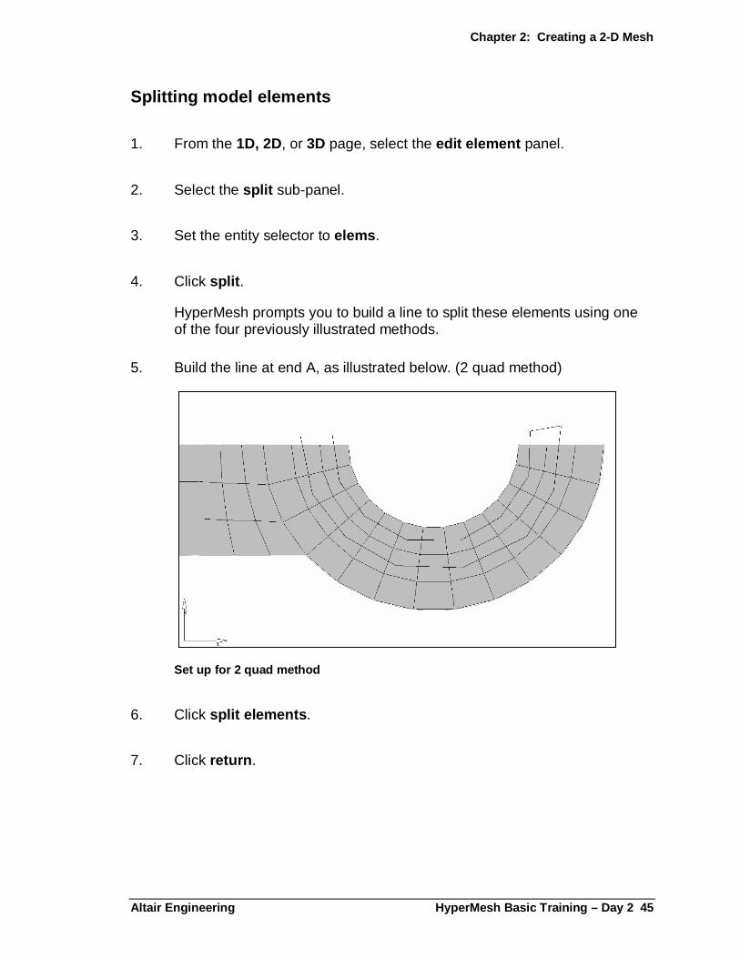
Splitting model elements
1. From the 1D, 2D, or 3D page, select the edit element panel.
2. Select the split sub-panel.
3. Set the entity selector to elems .
4. Click split .
HyperMesh prompts you to build a line to split these elements using one of the four previously illustrated methods.
5. Build the line at end A, as illustrated below. (2 quad method)
Set up for 2 quad method
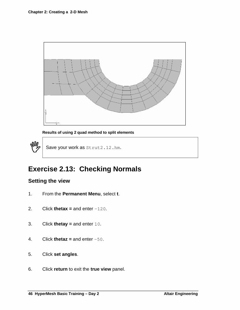
6. Click split elements .
7. Click return .
Chapter 2: Creating a 2-D Mesh
46 HyperMesh Basic Training – Day 2 Altair Enginee ring
Results of using 2 quad method to split elements
� Save your work as Strut2.12.hm .
Exercise 2.13: Checking Normals
Setting the view
1. From the Permanent Menu , select t.
2. Click thetax = and enter –120 .
3. Click thetay = and enter 10.
4. Click thetaz = and enter –50 .
5. Click set angles .
6. Click return to exit the true view panel.

Chapter 2: Creating a 2-D Mesh
Altair Engineering HyperMesh Basic Training – Day 2 47
7. From the Permanent Menu select view .
8. Click Save 3 =.
9. Move the mouse outside the borders of the pop-up menu.
Checking normals
1. From the Tool page, select the normals panel.
2. Select the elements sub-panel.
3. Set the entity selector to elems .
4. Click elems and select displayed .
5. Click display normals .
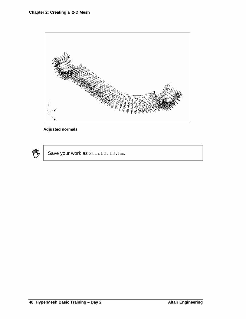
Arrows indicating the element normal direction are displayed. Because you used different methods to create the mesh, not all normals point in the same direction.
6. To adjust the normals, click the yellow elem box under orientation , then select one of the elements whose normal is pointing outward. Click adjust normals to modify the element normals. See image on the following page.
Chapter 2: Creating a 2-D Mesh
48 HyperMesh Basic Training – Day 2 Altair Enginee ring
Adjusted normals
� Save your work as Strut2.13.hm .
Altair Engineering HyperMesh Basic Training – Day 2 49
Chapter 3: Creating a 3-D Mesh
Exercise 3.1: Using the Linear Solid Panel
The linear solid panel creates a solid mesh of hexahedral or pentahedral elements between two similar surface meshes. Each surface mesh must have the same number and layout of elements (i.e. rows and columns) but the size and shape may differ.
Creating another layer of shell elements
1. From the Tool page, select the translate panel.
2. Set the entity selector to elems .
3. Click elems and select by collecto r.
4. Pick the 2D_endA component collector and click select .
5. Click elems and select save .
This saves the selected elements to a buffer region which will be retrieved later in the exercise.
6. Click elems and select duplicate .
7. Click original comp to copy the duplicate elements to 2D_endA .
8. Set the direction entity selector to x axis .
Chapter 3: Creating a 3-D Mesh
50 HyperMesh Basic Training – Day 2 Altair Enginee ring
9. Set the toggle to magnitude = and enter 48.0 .
10. Select translate - .
11. To exit the translate panel, select return .
Creating solid elements with the linear solid panel
1. From the global panel, set the current component collector to 3D_endA .
2. From the Permanent Menu , click view and select restore3 .
3. From the 3D page, select the linear solid panel.
4. Under from: click elems and select retrieve .
This retrieves the elements saved in the previous exercise from the buffer region.
5. Under to: click elems and select one of the elements from the 2D_endA component translated in the previous exercise.
6. Under to: click elems and pick by attached .
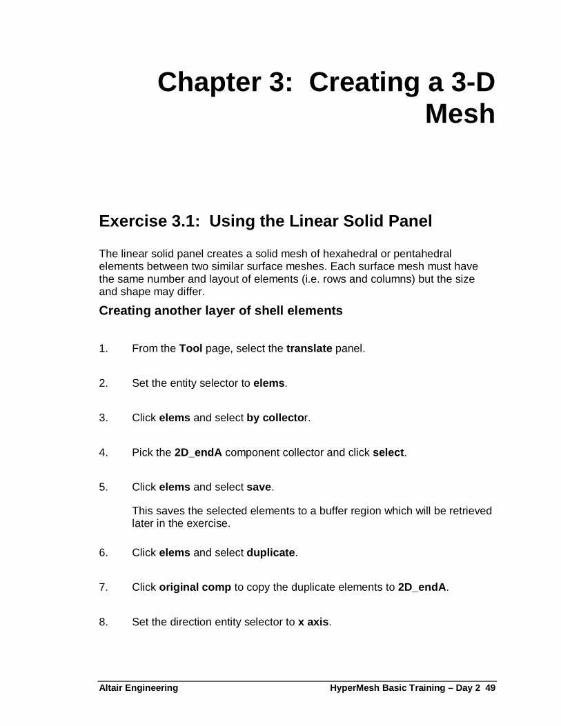
7. Under the upper alignment: direction entity selector, specify the nodes N1, N2, and N3 as shown in the diagram on the next page.
8. Under the lower alignment: direction entity selector, specify the nodes N1, N2, and N3 as shown in the diagram on the next page.
Chapter 3: Creating a 3-D Mesh
Altair Engineering HyperMesh Basic Training – Day2 51
Setting the alignments
9. Set the toggle to the distribute layers option to create evenly distributed solid layers.
10. Click density = and enter 3.
11. Click solids to create the solid elements.
12. To exit the linear solid panel, click return .
� Save your work as strut. 3.01.hm .
N1
N1 N2
N3
“from” allignment
N1 N2
N3 “to” allignment

Chapter 3: Creating a 3-D Mesh
52 HyperMesh Basic Training – Day 2 Altair Enginee ring
Exercise 3.2: Using the Solid Map Panel
The solid map panel allows you to create a mesh of solid elements by first extruding an existing 2-D finite element mesh, and then mapping the extruded mesh into a volume. To create a mesh, you must define a volume, select a mesh, and provide the number of elements to be created when the mesh is extruded. If you desire, also provide a biasing factor.
1. From the global panel, set the current component collector to 3D_endB .
2. From the Permanent Menu , click view and select restore3
3. From the macro menu , under Display: click geom on
4. From the 3D page, select the solid map panel.
5. Select the end only sub-panel.
6. Set the entity selector under source: to surf .
7. Pick the surface around the elements in the 2D_endB component.
8. Set the entity selector after end: to lines .
9. Pick the 4 lines parallel to the source surface.
10. Under elems to drag: click elems and select by collector .
11. Pick 2D_endB and click select .
12. Click density = and enter 6.
13. Click mesh .
14. To exit the solid map panel, click return .
Chapter 3: Creating a 3-D Mesh
Altair Engineering HyperMesh Basic Training – Day2 53
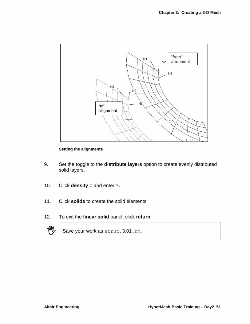
Solid map mesh
� Save your work as strut. 3.02.hm .
Exercise 3.3: Using the Element Offset Panel
The elem offset panel allows you to create and modify elements by offsetting them from a mesh of plate or shell elements. The element normals define the direction in which the elements will be offset.
1. From the global panel, set the current component collector to 3D_arm .
2. From the 3D page, select the elem offset panel.
3. Select the solid layers sub-panel.
4. Select elems and pick the elements in 2D_arm using the by collector selection method.
5. Click numbers of layers = and enter 3.
6. Click initial offset = and enter 0.0 .
7. Click total thickness = and enter 48.0 .
Chapter 3: Creating a 3-D Mesh
54 HyperMesh Basic Training – Day 2 Altair Enginee ring
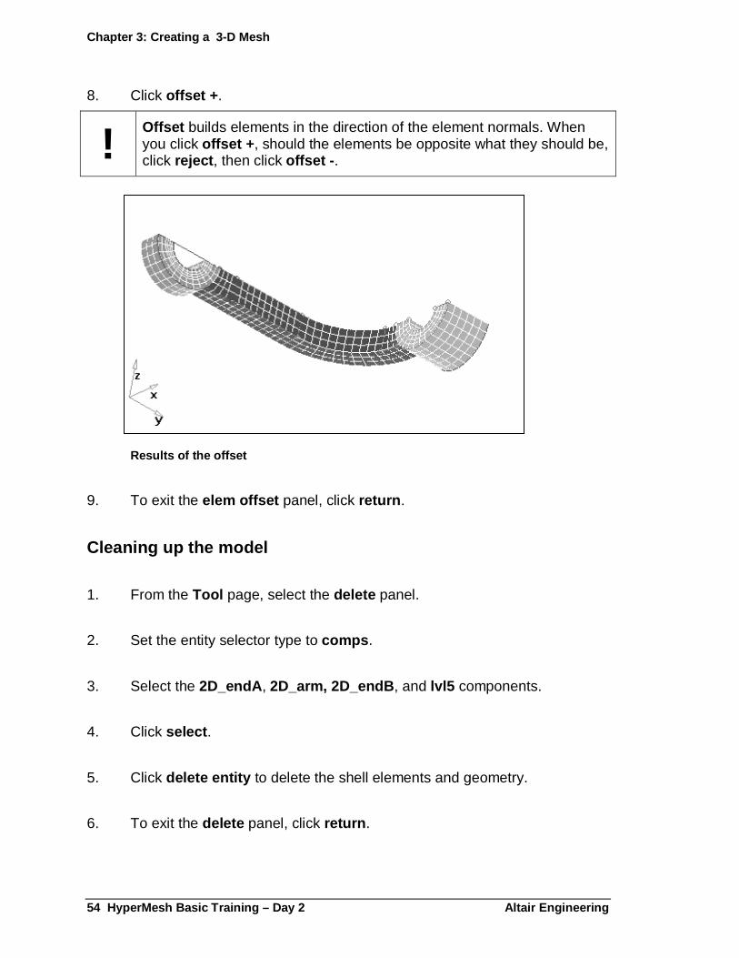
8. Click offset + .
! Offset builds elements in the direction of the element normals. When you click offset + , should the elements be opposite what they should be, click reject , then click offset - .
Results of the offset
9. To exit the elem offset panel, click return .
Cleaning up the model
1. From the Tool page, select the delete panel.
2. Set the entity selector type to comps .
3. Select the 2D_endA , 2D_arm, 2D_endB , and lvl5 components.
4. Click select .
5. Click delete entity to delete the shell elements and geometry.
6. To exit the delete panel, click return .

Chapter 3: Creating a 3-D Mesh
Altair Engineering HyperMesh Basic Training – Day2 55
� Save your work as strut.3.03.hm .
Exercise 3.4: Checking Element Connectivity
Just as the edges panel identifies connectivity problems for shell elements, the faces panel identifies and corrects connectivity problems for solid elements. Any face of a solid element not shared with a neighboring solid is identified with a 2-D plot element in the ^faces component.
1. From the Tool page, select the faces panel.
2. Select the 3D_endA, 3D-arm and 3D_endB components that contain the solid elements.
3. Click find faces .
4. Use the disp panel to display only the ^faces elements.
5. Use the vis panel to display the ^faces elements in hidden line with mesh lines mode.
� The disp and vis panels are the only panels in HyperMesh that cannot be interrupted by using the function keys on the keyboard. Return out of these panels prior to using the function keys to access other panels.
6. Press F1 to access the hidden line panel.
7. Click fill plot.
8. Select the cutting sub-panel.
9. Activate xy plane and trim planes .
Chapter 3: Creating a 3-D Mesh
56 HyperMesh Basic Training – Day 2 Altair Enginee ring
10. Pick the plane in the graphics area and drag the mouse pick handle to move the plane through the model to view its internal faces.
At the interfaces between the end regions and the arm, you can see face elements in the interior of the model. This indicates a break in the connectivity at these locations.
11. Click return .
12. Click delete faces .
13. Use the disp panel to display all the elements.
14. Use the vis panel to display the 3D_endA elements as transparent and the 3D_endB elements as hidden line with mesh lines .
15. Click preview equiv .
16. Adjust tolerance = until 24 coincident nodes are found.
� Increase the tolerance in small increments until all the nodes at the interfaces are identified. If any other nodes are identified, those elements may be collapsed once the equivalencing is performed.
17. Click equivalence .
The nodes are replaced to the location of the lowest node ID.
Chapter 3: Creating a 3-D Mesh
Altair Engineering HyperMesh Basic Training – Day2 57
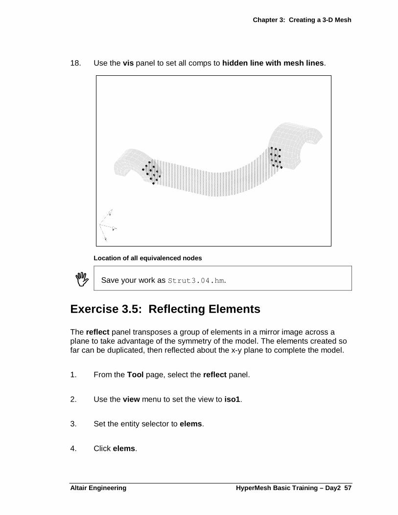
18. Use the vis panel to set all comps to hidden line with mesh lines .
Location of all equivalenced nodes
� Save your work as Strut3.04.hm .
Exercise 3.5: Reflecting Elements
The reflect panel transposes a group of elements in a mirror image across a plane to take advantage of the symmetry of the model. The elements created so far can be duplicated, then reflected about the x-y plane to complete the model.
1. From the Tool page, select the reflect panel.
2. Use the view menu to set the view to iso1 .
3. Set the entity selector to elems .
4. Click elems .

Chapter 3: Creating a 3-D Mesh
58 HyperMesh Basic Training – Day 2 Altair Enginee ring
5. Select all the solid elements.
6. Click elems again.
7. Select duplicate .
! Only use the duplicate function once! Even though on the screen nothing appears to have changed, all elements in the database have been duplicated.
If you duplicate a second time, the number of elements doubles and when you equivalence the nodes, the elements collapse.
8. Put the copied elements into the original comp .
9. Set the direction selector to z-axis to specify the reflecting plane.
10. Pick any node along the flat face (x-y plane) as the base node for reflecting the elements.
11. Click reflect .
12. Click return .
Checking connectivity
Following the same procedure as in Exercise 3.4, check the connectivity along the middle seam of the model. Do this in transparent mode.
1. From the tool page, select the faces panel.
2. Click comps and select all .
3. Display all of the elements in transparent mode using the vis panel.
Chapter 3: Creating a 3-D Mesh
Altair Engineering HyperMesh Basic Training – Day2 59
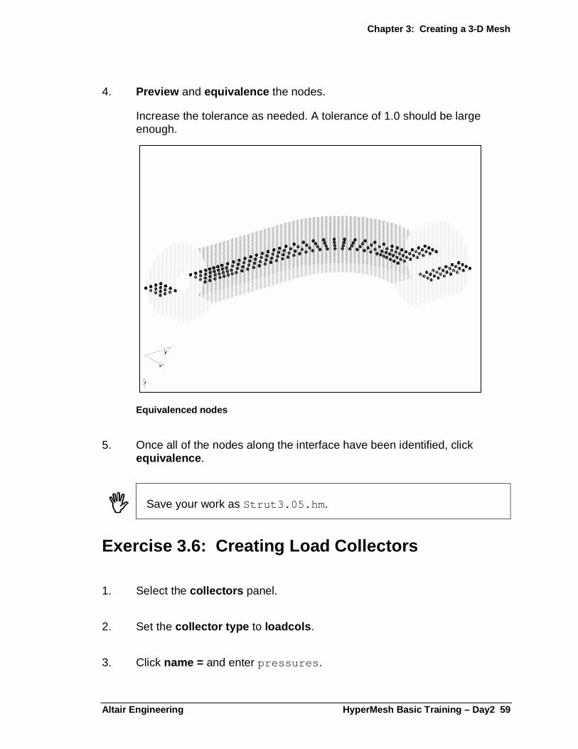
4. Preview and equivalence the nodes.
Increase the tolerance as needed. A tolerance of 1.0 should be large enough.
Equivalenced nodes
5. Once all of the nodes along the interface have been identified, click equivalence .
� Save your work as Strut3.05.hm .
Exercise 3.6: Creating Load Collectors
1. Select the collectors panel.
2. Set the collector type to loadcols .
3. Click name = and enter pressures .
Chapter 3: Creating a 3-D Mesh
60 HyperMesh Basic Training – Day 2 Altair Enginee ring
4. Set creation method: to no card image .
5. Click color and select a color.
6. Click create .
7. Click name = and enter constraints .
8. Click color and select a color.
9. Click create .
� Save your work as Strut3.06.hm .
Exercise 3.7: Creating Pressures
In this exercise, isolate a small group of elements and create pressures.
1. Use the view panel to select the front view.
2. Zoom in on end A.
3. From the global panel, click loadcol = and select pressures.
4. From the BC’s page, select the pressures panel.
5. Press the F5 key to access the mask panel.
6. Set the entity selector to elems .
7. Click elems and select by window .
Chapter 3: Creating a 3-D Mesh
Altair Engineering HyperMesh Basic Training – Day2 61
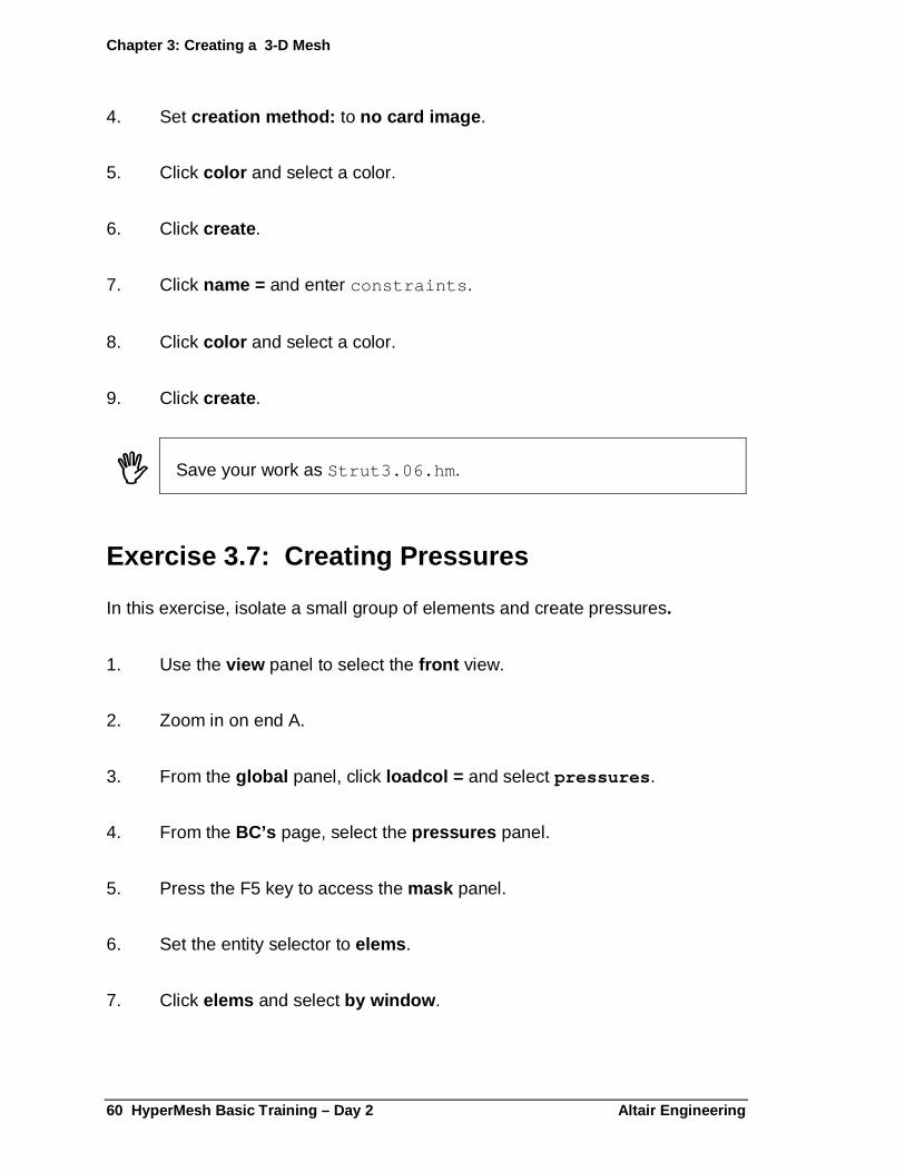
8. Draw the window as illustrated below.
Elements selected by window
9. Select the exterior option.
10. Click select entities .
11. Click mask .
12. Click return to go back to the pressures panel.
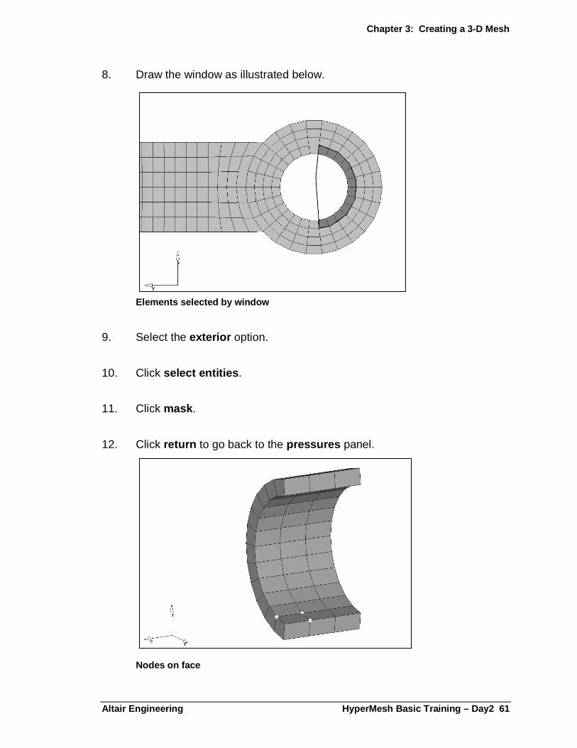
Nodes on face
Chapter 3: Creating a 3-D Mesh
62 HyperMesh Basic Training – Day 2 Altair Enginee ring
13. Click view and select iso1 .
14. Click elems and select displayed .
15. Click magnitude = and enter 25 .
16. Set the upper toggle to the uniform size option.
17. Click uniform size = and enter 10 .
18. Click the toggle to the nodes on face option and pick the nodes shown in the illustration above.
19. Click create .
Completed pressures
20. Click return .
21. From the Tool page, select the mask panel.
Chapter 3: Creating a 3-D Mesh
Altair Engineering HyperMesh Basic Training – Day2 63
22. Click unmask all .
23. To exit the mask panel, click return .
� Save your work as Strut3.07.hm .
Exercise 3.8: Creating Constraints
1. From the global panel, click load col = and select constraints .
2. From the BC’s page, select the constraints panel.
3. Click view and select right .
4. Pick all the nodes on the inner surface of the hole in end B.
5. Click size = and enter 5.
6. Activate the degrees of freedom, dof1-dof3 .
7. Set dof1-dof3 values to 0.00 .
8. Click create .
Chapter 3: Creating a 3-D Mesh
64 HyperMesh Basic Training – Day 2 Altair Enginee ring
9. To exit the constraint panel, click return .
Creating constraints
� Save your work as Strut3.8.hm .
Exercise 3.9: Creating Load Steps
1. From the BC’c page, select the load steps panel.
2. Click name = and enter initial_load .
3. Click loadcols and select the pressures and constraints load collectors.
4. Click select .
5. Click create .
6. To exit the load steps panel, click return .
Chapter 3: Creating a 3-D Mesh
Altair Engineering HyperMesh Basic Training – Day2 65
Exercise 3.10: Creating an Output Request Control Card
The OptiStruct solver provides results output in many common formats, such as HyperMesh binary results files, NASTRAN .pch and OP2 files, and Altair H3D. The default output file format is HyperMesh binary (.res).
Use the FORMAT control card to define the results file output. Multiple formats can be requested.
In this exercise, add a second output request for the Altair H3D format. This will output a H3D file with all of the simulation results. In addition, you will get an HTML report with an embedded version of HyperView Player.
1. From the BC’s page select the control cards panel.
2. Select the FORMAT control card.
3. In the main panel, enter 2 for the number_of_formats .
This will create an additional FORMAT line in the card image preview.
4. Click the HM button for the new format line.
A pop-up menu appears with a list of available output formats. For details on the format options, see the section in the online help under OptiStruct / Data Formats / I/O Options.
5. Select the HYPER or H3D option.
6. Click return to go back to the main BC’s page menu.
Exercise 3.11: Writing the Analysis Deck
1. Select the files panel.
2. Select the export sub-panel.
Chapter 3: Creating a 3-D Mesh
66 HyperMesh Basic Training – Day 2 Altair Enginee ring
3. Double-click template = and select optistruct if it is not already specified in this field.
4. Click file name = and enter a name for the analysis deck (be sure to use the .fem extension).
5. Click write .
Exercise 3.12: Running the OptiStruct Solver
1. From the BC’s page, select the solver panel.
2. Select the OptiStruct solver.
3. Click input file = and select your OptiStruct file.
4. Click solve .
.

Altair Engineering HyperMesh Basic Training – Day 2 67
Chapter 4: Post-Processing
This section explains how to view the analysis results of a model. The contour , deformed , and transient panels are used to view stress and displacement. The titles panel is used to label the image. In the X-Y plotting module, you interactively create an XY plot of the displacement vs. time for selected nodes of the model.
� Set the graphics engine to performance mode to use these exercises.
Analyzing Results The post-processing panels are located on the Post page of the main menu. The contour panel allows you to view a graphical representation of the analysis results of your model. You can use the legend sub-panel to change the plot colors and the maximum and minimum values of the legend.
� You will need to enter a results file in the results file = field on the results sub-panel of the files panel.
Chapter 4: Post-processing
68 HyperMesh Basic Training – Day 2 Altair Enginee ring
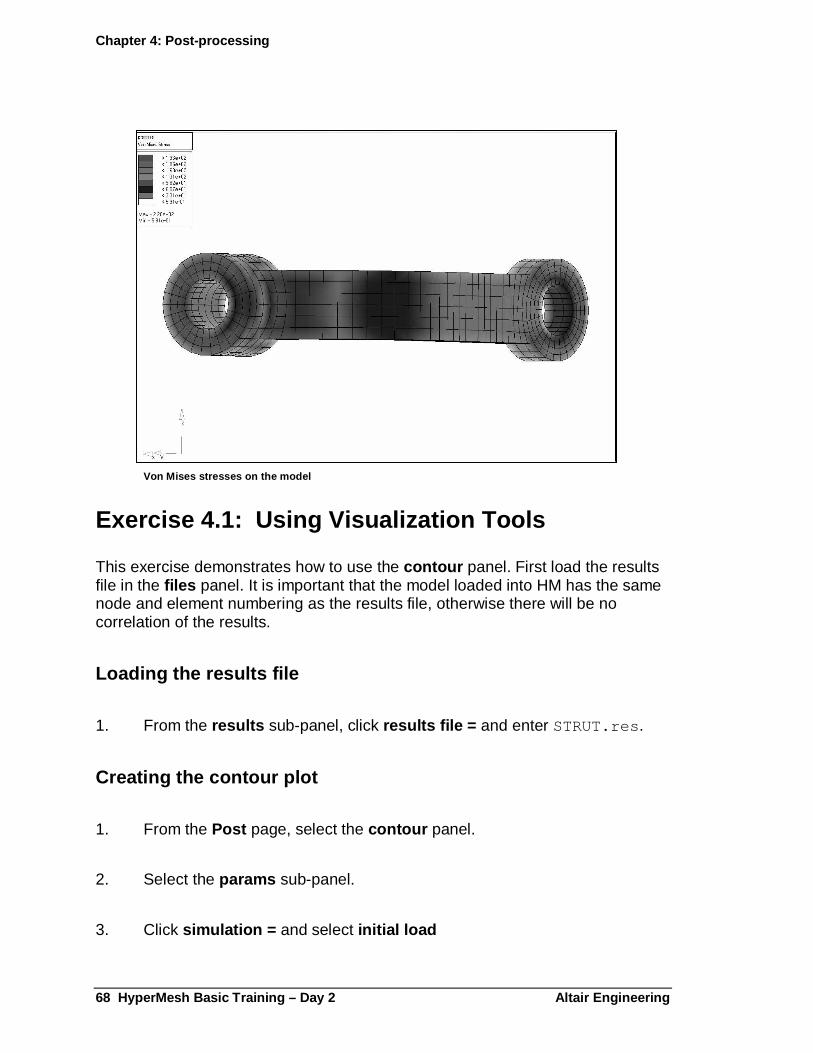
Von Mises stresses on the model
Exercise 4.1: Using Visualization Tools
This exercise demonstrates how to use the contour panel. First load the results file in the files panel. It is important that the model loaded into HM has the same node and element numbering as the results file, otherwise there will be no correlation of the results.
Loading the results file
1. From the results sub-panel, click results file = and enter STRUT.res .
Creating the contour plot
1. From the Post page, select the contour panel.
2. Select the params sub-panel.
3. Click simulation = and select initial load

Chapter 4: Post-processing
Altair Engineering. HyperMesh Basic Training – Day 2 69
4. Click data type = and select VonMises .
5. Activate min/max titles .
6. Click contour .
This color-codes your solid model based on the data type selected. The contour function gives a smooth transition between nodal values.
Changing the legend
1. Select the legend sub-panel.
This allows you to set the range of the legend.
2. Click the upper toggle to the maximum = option and enter 200 .
3. Click contour .
All areas with stresses higher than or equal to 200 MPa display in red.
4. Click the lower toggle to the find minimum option.
5. Click contour .
Changing the cutting planes
1. Select the cutting sub-panel.
This panel allows you to control a maximum of three cutting planes. These planes can be interactively translated by using the mouse.
2. Activate xz plane and trim planes .
You may need to select reverse to see the contoured plane, depending on your view.
3. Move the courser to the contour plane.
Chapter 4: Post-processing
70 HyperMesh Basic Training – Day 2 Altair Enginee ring
4. Hold the left mouse button down and drag the mouse to translate the plane on the model.
5. Turn off all the options in the cutting sub-panel.
Viewing isosurfaces
1. Select the isosurface sub-panel.
In the isosurface sub-panel, you can view surfaces of constant value. It allows you to visualize high stress areas in a fully interactive environment.
2. Set the toggle to the legend based option.
3. Activate show .
This feature creates seven separate isosurfaces, one for each color block in the legend.
4. Set the toggle to the value based option.
This feature creates one isosurface based on the given value.
5. Click the arrow in the legend and drag it to interactively change the isosurface.
6. Turn off the isosurfs .
Exercise 4.2: Using the Deformed Panel
The deformed panel displays analysis results as an animation of the deformation. This panel allows you to view a deformed plot of the model overlaid on the undeformed plot. This can be exaggerated using the scale factor option. You can also display linear and modal animations of the results and use cutting planes and isosurfaces during animation.
This exercise demonstrates how to display the deformed view of the model.
1. From the Post page, select the deformed panel.

Chapter 4: Post-processing
Altair Engineering. HyperMesh Basic Training – Day 2 71
2. Click simulation = and select initial_load .
3. Click data type = and select displacement .
4. Click view and select bottom .
5. Click deform .
6. Click frames = and enter 10 .
7. Click linear .
This displays the displacement in linear mode and allows you to create an AVI file using the animation controls.
8. Click create replay .
This creates a replay file that can be played back in the replay panel. The file is given the name, replay#.rpl.
9. Click return .
10. Click data type = and select Von Mises .
11. Click linear .
12. Click create replay .
This creates an additional replay file with the animation of the displacement, and the contour of the Von Mises stresses.
13. Click create H3D .
This creates a Hyper3D file for viewing in HyperView Player.
14. To exit the animation panel, click return .
15. To exit the deformed panel, click return .
Chapter 4: Post-processing
72 HyperMesh Basic Training – Day 2 Altair Enginee ring
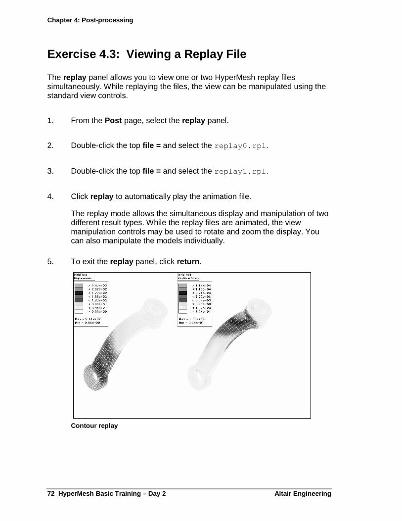
Exercise 4.3: Viewing a Replay File
The replay panel allows you to view one or two HyperMesh replay files simultaneously. While replaying the files, the view can be manipulated using the standard view controls.
1. From the Post page, select the replay panel.
2. Double-click the top file = and select the replay0.rpl .
3. Double-click the top file = and select the replay1.rpl .
4. Click replay to automatically play the animation file.
The replay mode allows the simultaneous display and manipulation of two different result types. While the replay files are animated, the view manipulation controls may be used to rotate and zoom the display. You can also manipulate the models individually.
5. To exit the replay panel, click return .
Contour replay
Chapter 4: Post-processing
Altair Engineering. HyperMesh Basic Training – Day 2 73
Exercise 4.4: Viewing the HTML Results Report
When the H3D results format is requested from OptiStruct, an HTML report is also created. In addition to a summary of the analysis, this report also has a link to launch the HyperView Player browser plug-in to interactively view the analysis results.
1. Minimize the HyperMesh window.
2. Use Windows Explorer to browse to your working directory.
3. Locate the strut.html file, and double click it.
4. Review the problem summary section.
5. In the Results summary section, click the link to launch HyperView Player in a separate browser window.
6. In the new window, select Subcase 1 - pressure for the Simulation.
7. Select Displacement or Von Mises Stresses for the results.
Chapter 4: Post-processing
74 HyperMesh Basic Training – Day 2 Altair Enginee ring
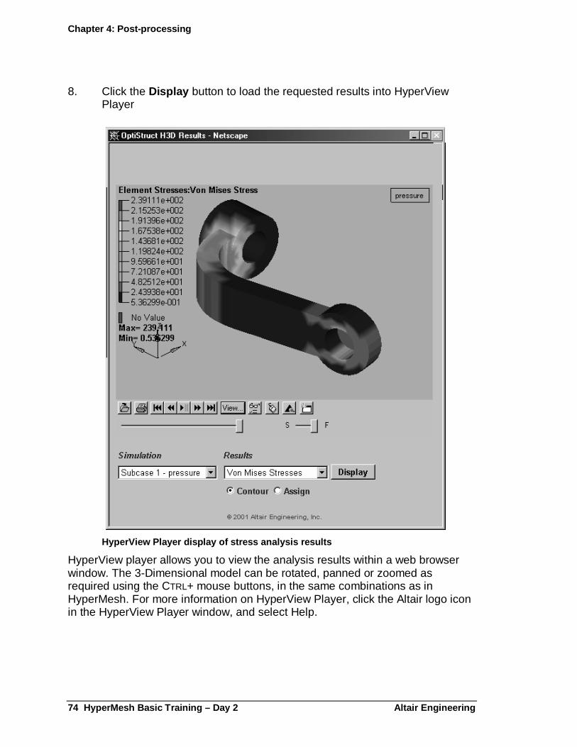
8. Click the Display button to load the requested results into HyperView Player
HyperView Player display of stress analysis results
HyperView player allows you to view the analysis results within a web browser window. The 3-Dimensional model can be rotated, panned or zoomed as required using the CTRL+ mouse buttons, in the same combinations as in HyperMesh. For more information on HyperView Player, click the Altair logo icon in the HyperView Player window, and select Help.
Altair Engineering HyperMesh Basic Training – Day 2 75
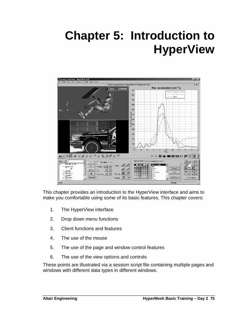
Chapter 5: Introduction to HyperView
This chapter provides an introduction to the HyperView interface and aims to make you comfortable using some of its basic features. This chapter covers:
1. The HyperView interface
2. Drop down menu functions
3. Client functions and features
4. The use of the mouse
5. The use of the page and window control features
6. The use of the view options and controls
These points are illustrated via a session script file containing multiple pages and windows with different data types in different windows.
Chapter 4: Post-processing
76 HyperMesh Basic Training – Day 2 Altair Enginee ring
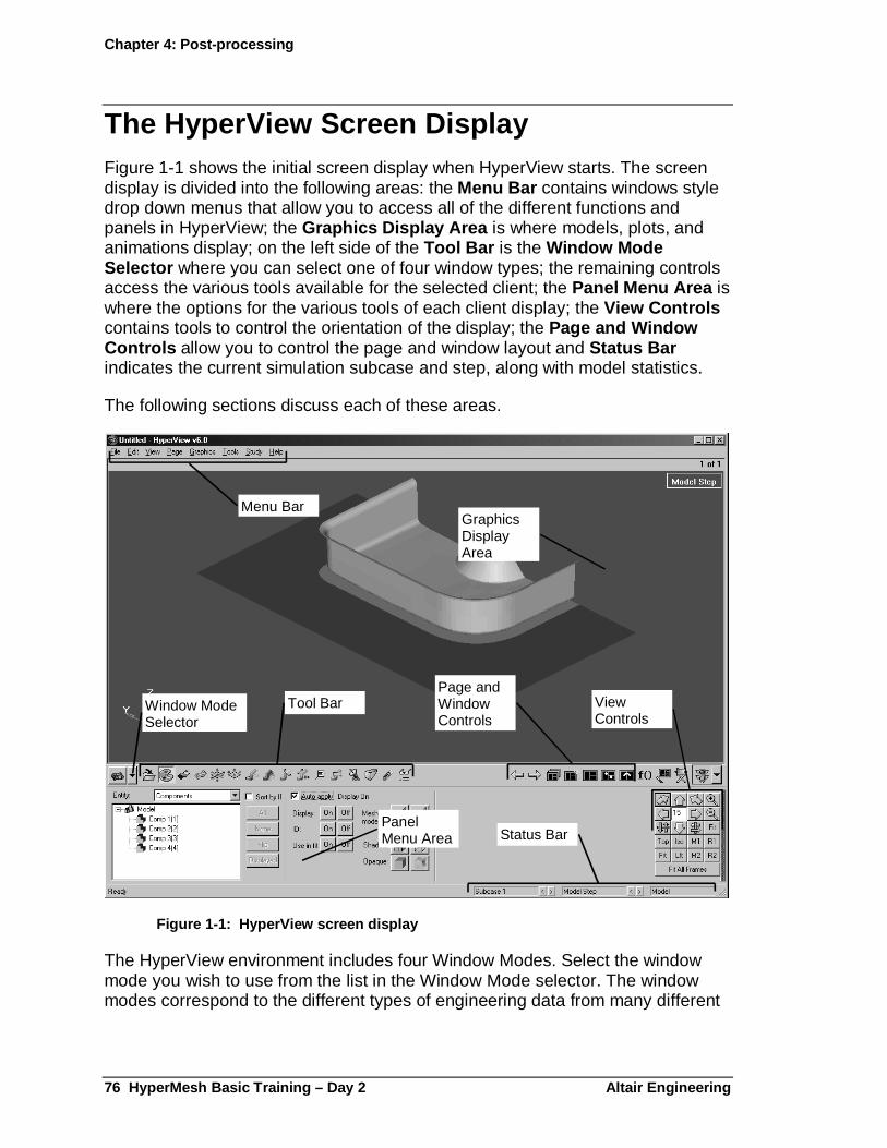
The HyperView Screen Display Figure 1-1 shows the initial screen display when HyperView starts. The screen display is divided into the following areas: the Menu Bar contains windows style drop down menus that allow you to access all of the different functions and panels in HyperView; the Graphics Display Area is where models, plots, and animations display; on the left side of the Tool Bar is the Window Mode Selector where you can select one of four window types; the remaining controls access the various tools available for the selected client; the Panel Menu Area is where the options for the various tools of each client display; the View Controls contains tools to control the orientation of the display; the Page and Window Controls allow you to control the page and window layout and Status Bar indicates the current simulation subcase and step, along with model statistics.
The following sections discuss each of these areas.
Window ModeSelector
GraphicsDisplayArea
Menu Bar
Tool BarPage andWindowControls
PanelMenu Area
ViewControls
Status Bar
Figure 1-1: HyperView screen display
The HyperView environment includes four Window Modes. Select the window mode you wish to use from the list in the Window Mode selector. The window modes correspond to the different types of engineering data from many different
Chapter 4: Post-processing
Altair Engineering. HyperMesh Basic Training – Day 2 77
sources. These are the four window types with a description of the files each type can process:
Animation : Displays CAE model and analysis results information from supported CAE solvers for finite element, kinematic, and multibody analysis. Additional solver formats are supported via translators that convert solver results to Altair's compact H3D binary format.
XY Plotting : A powerful data analysis tool that interfaces with many popular file formats. The sophisticated math engine is capable of processing complex mathematical expressions with large data sets. Altair's Templex text and numeric processor allows the introduction of advanced annotations and notes.
Video : Displays and synchronizes digital video data to CAE and XY Plot information. AVI, BMP, TIFF and JPEG file formats are supported.
Text : Allows text files to be viewed and edited directly in the HyperView environment. Altair's Templex language can be used to embed mathematical functionality.
A session in HyperView can comprise multiple pages. Each page can hold one or more windows with each window holding one type of datum. Multi-window sessions may have all four clients represented.
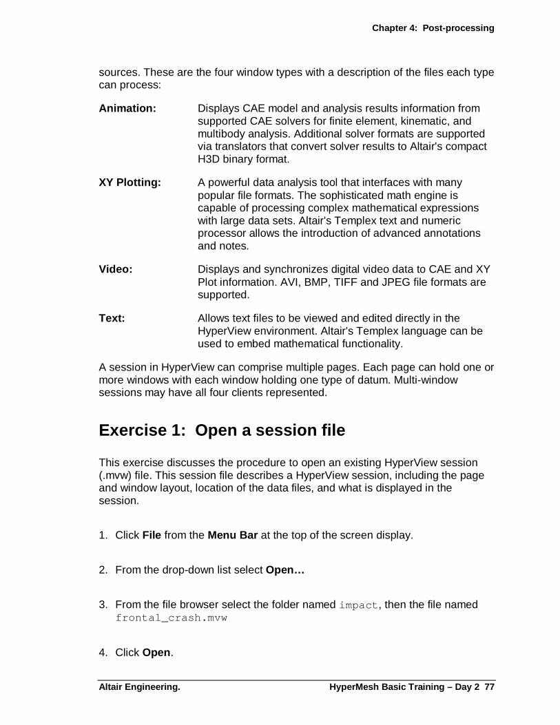
Exercise 1: Open a session file
This exercise discusses the procedure to open an existing HyperView session (.mvw) file. This session file describes a HyperView session, including the page and window layout, location of the data files, and what is displayed in the session.
1. Click File from the Menu Bar at the top of the screen display.
2. From the drop-down list select Open…
3. From the file browser select the folder named impact , then the file named frontal_crash.mvw
4. Click Open .
Chapter 4: Post-processing
78 HyperMesh Basic Training – Day 2 Altair Enginee ring
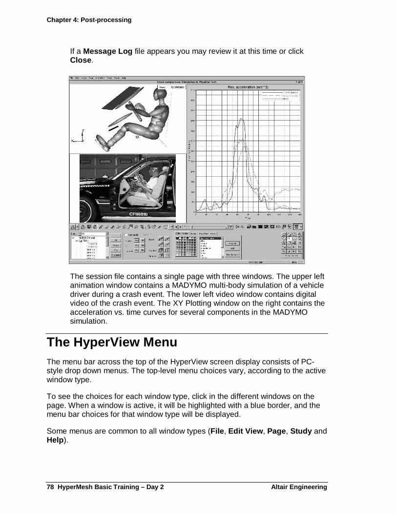
If a Message Log file appears you may review it at this time or click Close .
The session file contains a single page with three windows. The upper left animation window contains a MADYMO multi-body simulation of a vehicle driver during a crash event. The lower left video window contains digital video of the crash event. The XY Plotting window on the right contains the acceleration vs. time curves for several components in the MADYMO simulation.
The HyperView Menu The menu bar across the top of the HyperView screen display consists of PC-style drop down menus. The top-level menu choices vary, according to the active window type.
To see the choices for each window type, click in the different windows on the page. When a window is active, it will be highlighted with a blue border, and the menu bar choices for that window type will be displayed.
Some menus are common to all window types (File , Edit View , Page, Study and Help ).
Chapter 4: Post-processing
Altair Engineering. HyperMesh Basic Training – Day 2 79
File Perform file operations pertaining to the HyperView session . Open and save session files, set preferences, export curve and animation data, print functions, etc.
� Session files are used to save the entire HyperView session – all pages and window layouts. Load the data files for the individual windows using the tool bar file functions.
Edit Cut and paste operations for windows and pages.
View Options affecting the overall layout of the HyperView session. Turn on or off common components, like the status bar at the bottom of the screen display, full screen mode, session browser, large icon mode, animation mini bar, or expand an active window to fill the graphics area.
Page Page functions control the window layout, cycle through the pages, title display and animation controls. The page functions are duplicated on the right side of the tool bar.
Study The Study menu is used to launch the Altair Study Wizard, a tool for parametric and optimization studies based on Design of Experiments (DOE)
Help Launch the online help and review message logs.
Window specific function menus are typically duplicated on the left side of the Tool bar. The following briefly describes the function menus for each of the window types.
Animation window function menus
Graphics All of the panels and functions for the animation client can be accessed here as well as on the left side of the tool bar. In addition, the current model properties can be used to review statistical and general model information.
Tools Start Custom Wizards, generate report templates, create custom Templex functions and control animation client options.
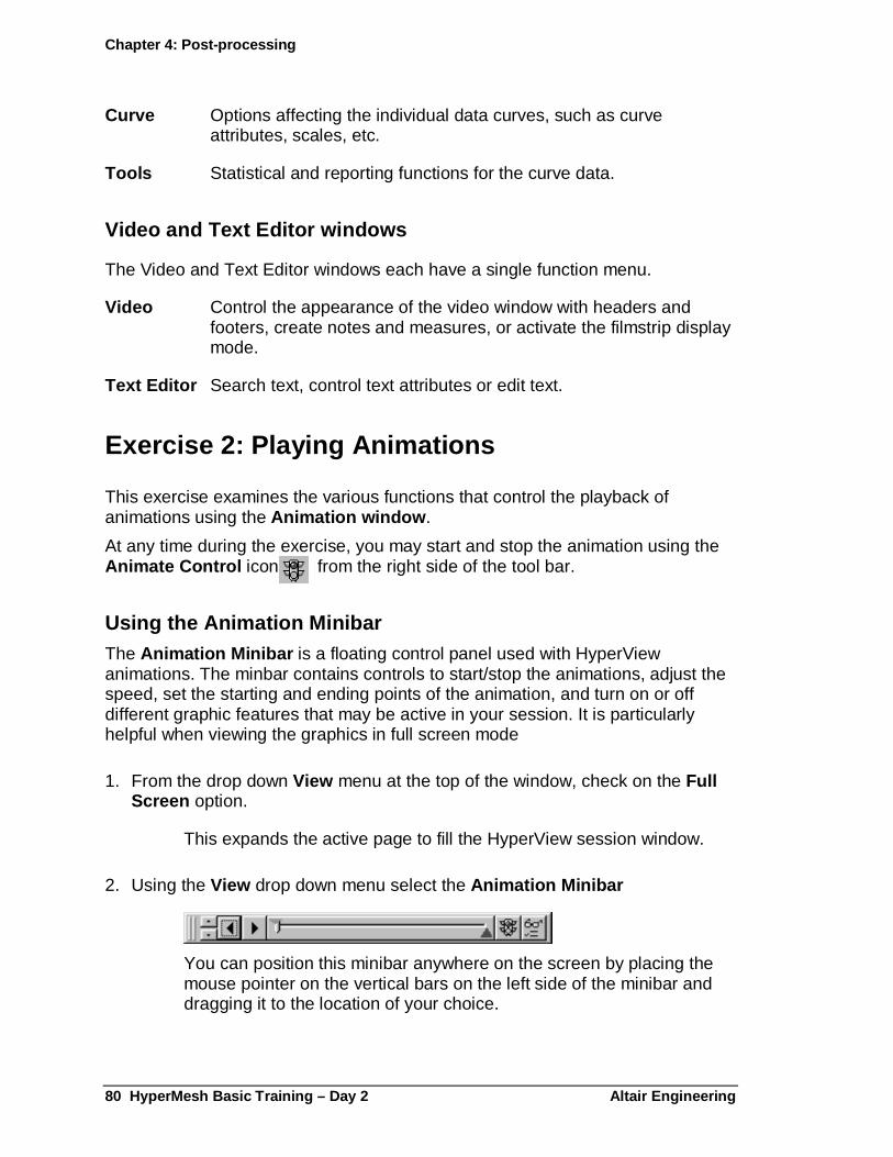
Plotting window function menus
Plot Options affecting the appearance of the plotting client window, such as headers and footers, background colors, legends and notes.
Chapter 4: Post-processing
80 HyperMesh Basic Training – Day 2 Altair Enginee ring
Curve Options affecting the individual data curves, such as curve attributes, scales, etc.
Tools Statistical and reporting functions for the curve data.
Video and Text Editor windows
The Video and Text Editor windows each have a single function menu.
Video Control the appearance of the video window with headers and footers, create notes and measures, or activate the filmstrip display mode.
Text Editor Search text, control text attributes or edit text.
Exercise 2: Playing Animations
This exercise examines the various functions that control the playback of animations using the Animation window .
At any time during the exercise, you may start and stop the animation using the Animate Control icon from the right side of the tool bar.
Using the Animation Minibar The Animation Minibar is a floating control panel used with HyperView animations. The minbar contains controls to start/stop the animations, adjust the speed, set the starting and ending points of the animation, and turn on or off different graphic features that may be active in your session. It is particularly helpful when viewing the graphics in full screen mode
1. From the drop down View menu at the top of the window, check on the Full Screen option.
This expands the active page to fill the HyperView session window.
2. Using the View drop down menu select the Animation Minibar
You can position this minibar anywhere on the screen by placing the
mouse pointer on the vertical bars on the left side of the minibar and dragging it to the location of your choice.

Chapter 4: Post-processing
Altair Engineering. HyperMesh Basic Training – Day 2 81
3. Start the animation by clicking the animate control icon, , from the minibar.
4. Vary the speed of the animation by clicking the up and down arrows on the left side of the Animation Minibar.
5. View each frame separately by stopping the animation, then clicking the right arrow to advance to the next frame or the left arrow to back up to the previous frame.
6. Manually animate the model by using the horizontal slider bar on the Animation Minibar.
7. To limit the playback to only a portion of the complete animation, use the green and red triangles above and below the slider to set the beginning and ending points for the animation.
8. Hide the Animation Minibar by selecting from the View menu the Animation minibar option again.
This removes the check mark and deselects the animation minibar.
9. Restore the panels in the view by turning off the Full screen mode from the View menu.
Using the Animation Controls Panel
The animation controls panel is used to control the starting and stopping points of the animation as well as the speed at which the animation is played.
1. Click the director’s chair icon to go to the animation control panel.
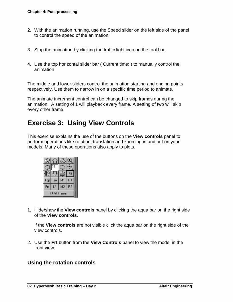
Chapter 4: Post-processing
82 HyperMesh Basic Training – Day 2 Altair Enginee ring
2. With the animation running, use the Speed slider on the left side of the panel to control the speed of the animation.
3. Stop the animation by clicking the traffic light icon on the tool bar.
4. Use the top horizontal slider bar ( Current time: ) to manually control the animation
The middle and lower sliders control the animation starting and ending points respectively. Use them to narrow in on a specific time period to animate.
The animate increment control can be changed to skip frames during the animation. A setting of 1 will playback every frame. A setting of two will skip every other frame.
Exercise 3: Using View Controls
This exercise explains the use of the buttons on the View controls panel to perform operations like rotation, translation and zooming in and out on your models. Many of these operations also apply to plots.
1. Hide/show the View controls panel by clicking the aqua bar on the right side of the View controls .
If the View controls are not visible click the aqua bar on the right side of the view controls.
2. Use the Frt button from the View Controls panel to view the model in the front view.
Using the rotation controls
Chapter 4: Post-processing
Altair Engineering. HyperMesh Basic Training – Day 2 83
3. The six arrow buttons on the view controls panel allow you to rotate the model incrementally. The up/down and left/right arrow pairs rotate the model about the horizontal or vertical screen axis. The curved arrows rotate the model clockwise or counter-clockwise within the plane of the screen.
4. The number in the middle of the arrows sets the rotation increment in degrees.
5. Try each of the arrow keys to see how the model rotates. With each click, the model rotates 15 degrees.
6. Click in the number field in the middle of the arrows and change the value to 45.
7. Try some of the arrow keys. The model now rotates 45 degrees with each click.
8. Change the rotation increment back to 15 degrees.
Remember that the CTRL key in combination with the left mouse button will activate the arc rotate mode.
Using the Zoom Controls
The magnifying glass and fit buttons allow you to zoom in or out on the model.
The positive magnifying glass zooms in to the model to get a closer look. To zoom out, use the negative magnifying glass icon .
Remember that the zoom factor is set using Tools / Options / View from the menu bar.
The Fit button under the magnifying glass will fill the model to the screen area.
The Fit All Frames button will consider the displacement of the model throughout the animation, and scale the view such that the entire displacement can be seen. This is useful for viewing animations with very large deformations, such as a drop test or kinematics model.
Another way to zoom is using the CTRL key in combination with the middle mouse button to draw a zoom window.
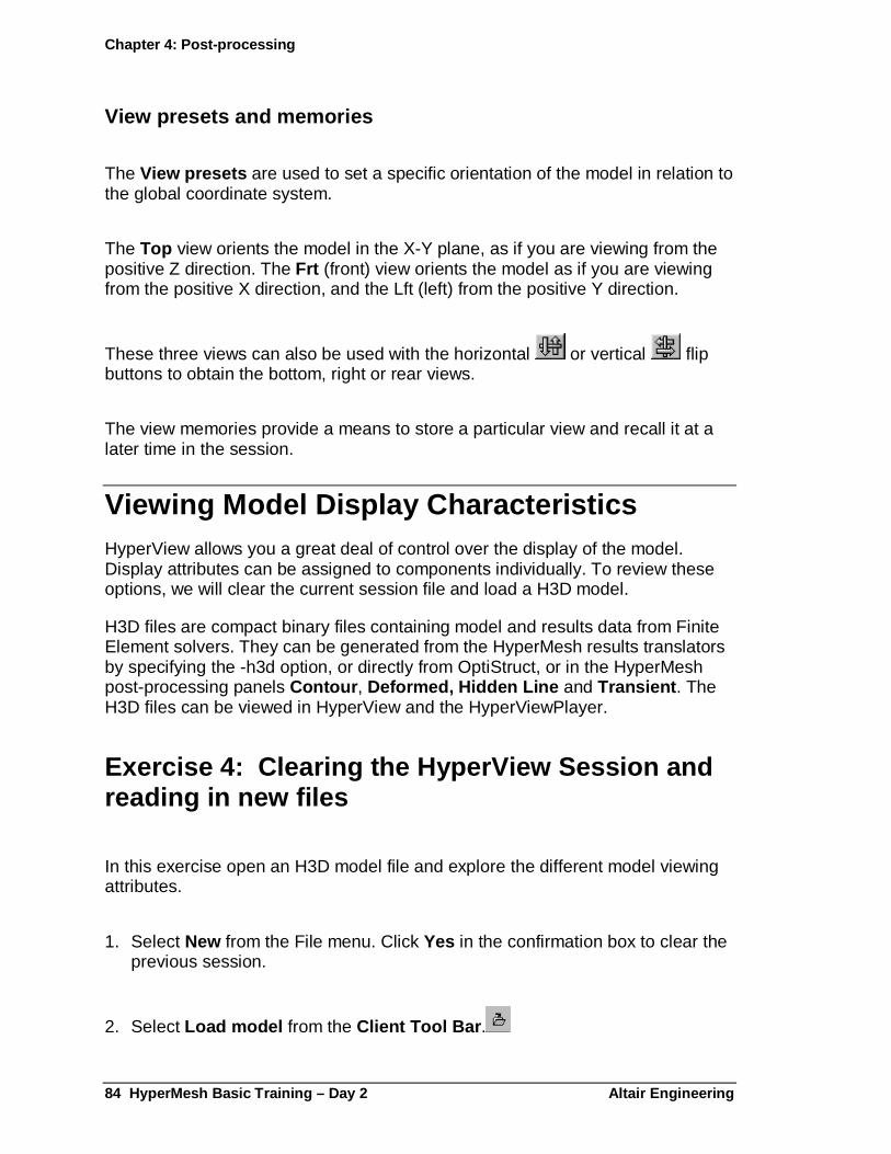
Chapter 4: Post-processing
84 HyperMesh Basic Training – Day 2 Altair Enginee ring
View presets and memories
The View presets are used to set a specific orientation of the model in relation to the global coordinate system.
The Top view orients the model in the X-Y plane, as if you are viewing from the positive Z direction. The Frt (front) view orients the model as if you are viewing from the positive X direction, and the Lft (left) from the positive Y direction.
These three views can also be used with the horizontal or vertical flip buttons to obtain the bottom, right or rear views.
The view memories provide a means to store a particular view and recall it at a later time in the session.
Viewing Model Display Characteristics HyperView allows you a great deal of control over the display of the model. Display attributes can be assigned to components individually. To review these options, we will clear the current session file and load a H3D model.
H3D files are compact binary files containing model and results data from Finite Element solvers. They can be generated from the HyperMesh results translators by specifying the -h3d option, or directly from OptiStruct, or in the HyperMesh post-processing panels Contour , Deformed, Hidden Line and Transient . The H3D files can be viewed in HyperView and the HyperViewPlayer.
Exercise 4: Clearing the HyperView Session and reading in new files
In this exercise open an H3D model file and explore the different model viewing attributes.
1. Select New from the File menu. Click Yes in the confirmation box to clear the previous session.
2. Select Load model from the Client Tool Bar .
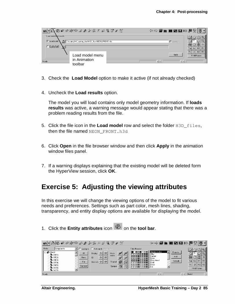
Chapter 4: Post-processing
Altair Engineering. HyperMesh Basic Training – Day 2 85
Load model menuin Animationtoolbar
3. Check the Load Model option to make it active (if not already checked)
4. Uncheck the Load results option.
The model you will load contains only model geometry information. If loads results was active, a warning message would appear stating that there was a problem reading results from the file.
5. Click the file icon in the Load model row and select the folder H3D_files , then the file named NEON_FRONT.h3d
6. Click Open in the file browser window and then click Apply in the animation window files panel.
7. If a warning displays explaining that the existing model will be deleted form the HyperView session, click OK.
Exercise 5: Adjusting the viewing attributes
In this exercise we will change the viewing options of the model to fit various needs and preferences. Settings such as part color, mesh lines, shading, transparency, and entity display options are available for displaying the model.
1. Click the Entity attributes icon on the tool bar .
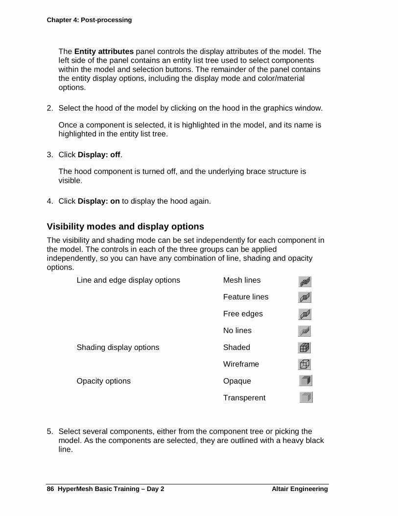
Chapter 4: Post-processing
86 HyperMesh Basic Training – Day 2 Altair Enginee ring
The Entity attributes panel controls the display attributes of the model. The left side of the panel contains an entity list tree used to select components within the model and selection buttons. The remainder of the panel contains the entity display options, including the display mode and color/material options.
2. Select the hood of the model by clicking on the hood in the graphics window.
Once a component is selected, it is highlighted in the model, and its name is highlighted in the entity list tree.
3. Click Display: off .
The hood component is turned off, and the underlying brace structure is visible.
4. Click Display: on to display the hood again.
Visibility modes and display options The visibility and shading mode can be set independently for each component in the model. The controls in each of the three groups can be applied independently, so you can have any combination of line, shading and opacity options.
Line and edge display options Mesh lines
Feature lines
Free edges
No lines
Shading display options Shaded
Wireframe
Opacity options Opaque
Transperent
5. Select several components, either from the component tree or picking the model. As the components are selected, they are outlined with a heavy black line.

Chapter 4: Post-processing
Altair Engineering. HyperMesh Basic Training – Day 2 87
6. Select the transparent mode.
7. Select the mesh lines options
8. Click none from the component list to complete the changes to the visibility.
Using the "auto apply" option
In the default mode, you select the component first, then select the display options to apply to it. This process reverses when you check auto apply . It applies the selected option to whichever components are selected. Only one display option may be changed at a time.
9. Check auto apply .
10. Select display off mode.
11. Click several components in the model.
As the component is selected, the display of that component is turned off.
12. Select display on .
13. Click all from the component list.
All of the components are turned back on.
14. Select the no lines display mode.
15. Click all from the component list.
16. Select the Opaque display mode.
17. Click all from the component list.
This returns the entire model to shaded mode with no lines.
18. Uncheck auto apply .
Chapter 4: Post-processing
88 HyperMesh Basic Training – Day 2 Altair Enginee ring
Changing the component color and material propertie s
Like the display options, the color and material properties are applied after selecting the components to apply them to.
19. Click all from the component list.
20. Pick a color from the color pallet.
All of the components are now displayed in the chosen color.
21. Select the front bumper by clicking on it in the graphics window.
22. Select tire from the material list. Scroll down the list using the scroll bar or arrows if necessary.
23. Select the windshield and side windows by clicking on the model.
24. Select the glass material.
You can edit the existing material properties using the property button, or create new materials using the add button. The material list can also be defined and saved in the preference file. See the online help under HyperView / Motion Script Reference for more information.
Exercise 6: Using the Perspective panel
The Perspective panel enables the model to be viewed with depth perception.
1. Click the perspective icon.
This adjusts the view if the model as though it has depth.
2. Select the option to use perspective view .
3. Adjust the Magnitude of the perspective and review the effect as you rotate the model.

Chapter 4: Post-processing
Altair Engineering. HyperMesh Basic Training – Day 2 89
Summary:
In this chapter, you were introduced to the HyperView interface. A session file was used to illustrate the different tool options within each of the clients, along with the animation controls and session options.
Next, the entity attribute settings and options were explored after loading a model file into the animation client. Finally, the perspective view was reviewed.

Altair Engineering HyperMesh Basic Training – Day 2 91
Chapter 6: Generating H3D files and Post Processing Modal Analysis Results in HyperView
H3D files are very compact binary files that can contain finite element model data and finite element results. H3D files can be generated from HyperMesh in the post processing panels, from the HyperMesh results translators, or directly from OptiStruct.
In this Chapter, explore three different methods of generating H3D files, then post process using HyperView Player and HyperView.
Exercise 1: Generating H3D files directly from OptiStruct
In this exercise, use HyperMesh to set up a control card requesting the OptiStruct solver to generate a H3D file directly, and also a NASTRAN .op2 format results file.
In a subsequent exercise, we’ll see how to translate the .op2 file into a H3D file using the hmnasto2 results translator.
Import a Finite Element model into HyperMesh
1. Start a HyperMesh session.
2. From the Geom page, select the Files panel.
3. Select the import sub-panel.

Chapter 5: Post-processing with HyperView
92 HyperMesh Basic Training – Day 2 Altair Enginee ring
4. Click the selector next to FE and select OPTISTRUCT from the pop-up menu.
5. Click the green import… button to bring up the file browser.
6. Locate the file rotor.fem , and double click on the filename.
7. Click return to go back to the Geom page.
8. Click the user prof… button on the Geom page to bring up the user profile selector.
9. Select OptiStruct from the drop down list, then click OK to load the OptiStruct user profile.
The OptiStruct user profile loads the OptiStruct output template and an OptiStruct specific macro page. Additionally, panel functions that do not apply to OptiStruct are removed, making navigation through HyperMesh simpler.
Creating an Output Request Control Card
The OptiStruct solver provides result output in many common formats, such as HyperMesh binary results files, Nastran .pch or .op2 files, and Altair .h3d. The default output is the HyperMesh binary (.res) format.
In this exercise, use the FORMAT control card to request the result file output in NASTRAN .op2 and Altair .h3d formats.
10. From the BCs page select the control card panel.
11. Select the FORMAT control card.
12. In the main panel, enter 3 for the number_of_formats .
This will create 2 additional FORMAT lines in the card image previewer.
The first requested output format will be the HM binary results file.
13. Click the HM button for the second format line.
A pop-up menu appears with a list of available output formats.
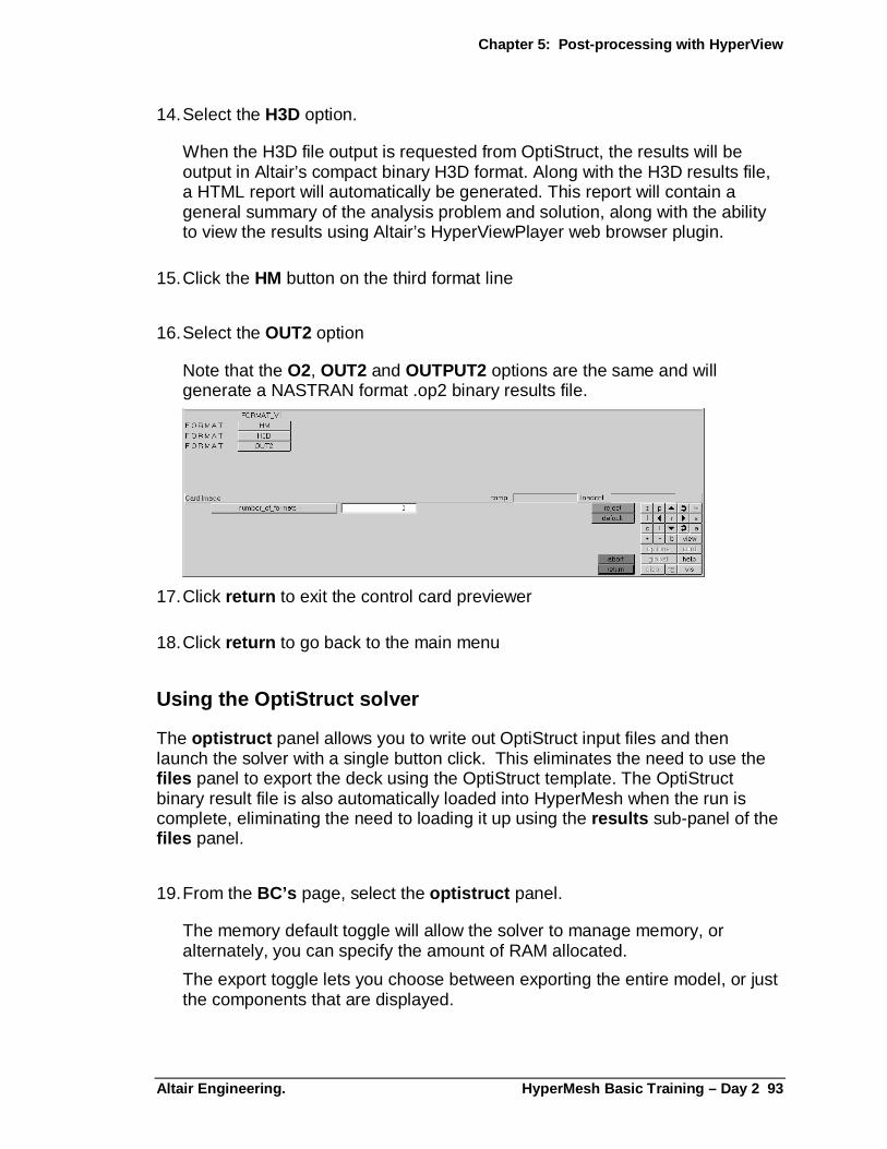
Chapter 5: Post-processing with HyperView
Altair Engineering. HyperMesh Basic Training – Day 2 93
14. Select the H3D option.
When the H3D file output is requested from OptiStruct, the results will be output in Altair’s compact binary H3D format. Along with the H3D results file, a HTML report will automatically be generated. This report will contain a general summary of the analysis problem and solution, along with the ability to view the results using Altair’s HyperViewPlayer web browser plugin.
15. Click the HM button on the third format line
16. Select the OUT2 option
Note that the O2, OUT2 and OUTPUT2 options are the same and will generate a NASTRAN format .op2 binary results file.
17. Click return to exit the control card previewer
18. Click return to go back to the main menu
Using the OptiStruct solver
The optistruct panel allows you to write out OptiStruct input files and then launch the solver with a single button click. This eliminates the need to use the files panel to export the deck using the OptiStruct template. The OptiStruct binary result file is also automatically loaded into HyperMesh when the run is complete, eliminating the need to loading it up using the results sub-panel of the files panel.
19. From the BC’s page, select the optistruct panel.
The memory default toggle will allow the solver to manage memory, or alternately, you can specify the amount of RAM allocated.
The export toggle lets you choose between exporting the entire model, or just the components that are displayed.
Chapter 5: Post-processing with HyperView
94 HyperMesh Basic Training – Day 2 Altair Enginee ring
A path and filename is specified by default in the file = field. In this case, it will use the name rotor.fem .
20. Click in the file = field and change the filename to rotor_run.fem
Change the name so to not overwrite the original input file,
21. Click optistruct to launch the solver process.
This launches another window and starts the OptiStruct solver. After a few seconds this message appears …Processing complete.
At this point, close the OptiStruct window.
22. Click return to go back to the main menu
A number of output files were written to the HyperMesh starting directory, including rotor_run.res , rotor_run.op2 and rotor_run.h3d , the three output files requested on the FORMAT control card.
Exercise 2: Viewing the HTML Results Report
When the H3D results format is requested from OptiStruct, a HTML report is also created. This report contains a summary of the analysis, and also has a link to launch the HyperView Player browser plug-in to interactively view the analysis results.
1. Minimize the HyperMesh and HyperView windows.
2. Use Windows Explorer to browse to your working directory.
3. Locate the rotor_run.html file and double click it.
4. Review the Problem summary section.
5. In the frame footer, select Subcase1 – Frequency for the Subcases selector.
6. Select one of the Eigen frequencies under Simulations.
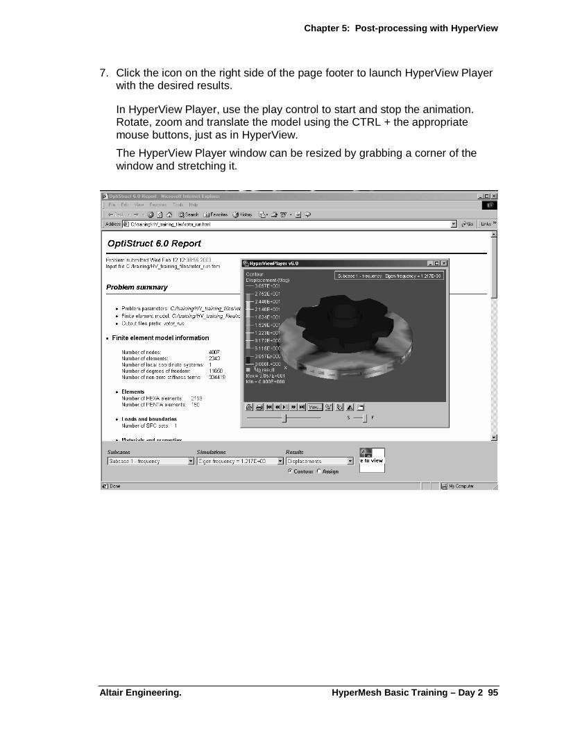
Chapter 5: Post-processing with HyperView
Altair Engineering. HyperMesh Basic Training – Day 2 95
7. Click the icon on the right side of the page footer to launch HyperView Player with the desired results.
In HyperView Player, use the play control to start and stop the animation. Rotate, zoom and translate the model using the CTRL + the appropriate mouse buttons, just as in HyperView.
The HyperView Player window can be resized by grabbing a corner of the window and stretching it.
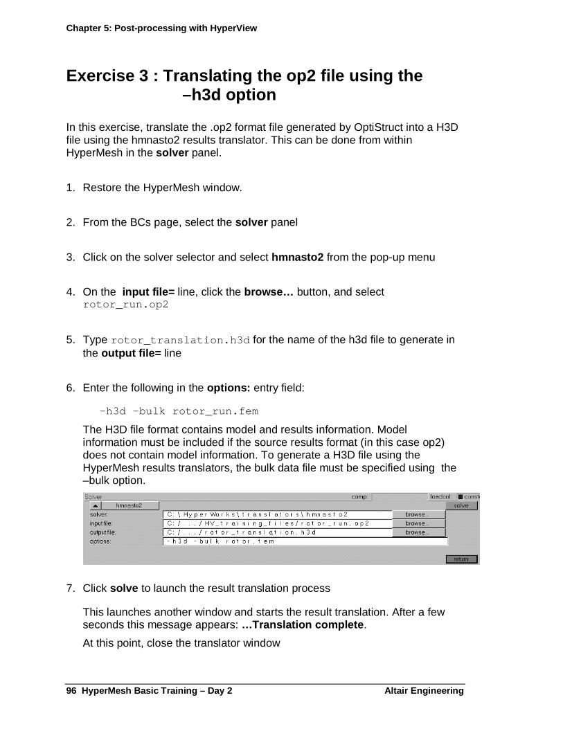
Chapter 5: Post-processing with HyperView
96 HyperMesh Basic Training – Day 2 Altair Enginee ring
Exercise 3 : Translating the op2 file using the –h3d option
In this exercise, translate the .op2 format file generated by OptiStruct into a H3D file using the hmnasto2 results translator. This can be done from within HyperMesh in the solver panel.
1. Restore the HyperMesh window.
2. From the BCs page, select the solver panel
3. Click on the solver selector and select hmnasto2 from the pop-up menu
4. On the input file= line, click the browse… button, and select rotor_run.op2
5. Type rotor_translation.h3d for the name of the h3d file to generate in the output file= line
6. Enter the following in the options: entry field:
–h3d –bulk rotor_run.fem
The H3D file format contains model and results information. Model information must be included if the source results format (in this case op2) does not contain model information. To generate a H3D file using the HyperMesh results translators, the bulk data file must be specified using the –bulk option.
7. Click solve to launch the result translation process
This launches another window and starts the result translation. After a few seconds this message appears: …Translation complete .
At this point, close the translator window

Chapter 5: Post-processing with HyperView
Altair Engineering. HyperMesh Basic Training – Day 2 97
8. Click return to return out of the solver panel.
Exercise 4 : Creating a H3D file containing the model information
H3D files created from the result translators contain the model information, but not the organization of the elements into various collectors like they do appear in HyperMesh. Since HyperView allows you to load a model and results from different files, a different H3D file, containing all of the collector and model organization information can be used while post processing the results generated in the previous exercise.
The H3D file containing the model organization information can be written from any of the HyperMesh post processing panels while in performance graphics mode. Using the hidden line panel, a H3D file containing only the model information can be generated.
1. From the Disp page of the macro menu, click per to work in performance graphics mode
2. From the Post page of the main menu area, select the hidden line panel
3. Click Fill Plot . A Hyper3D button appears.
4. Click Hyper3D
A H3D file called anim1.h3d is created in the working directory.
5. Click return to return out of the hidden line panel.
6. Quit HyperMesh using the quit button on the right side of the header bar. It is not necessary to save the file.
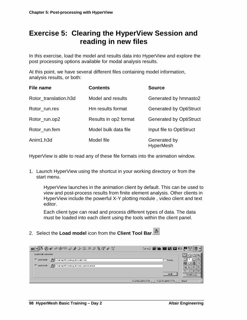
Chapter 5: Post-processing with HyperView
98 HyperMesh Basic Training – Day 2 Altair Enginee ring
Exercise 5: Clearing the HyperView Session and reading in new files
In this exercise, load the model and results data into HyperView and explore the post processing options available for modal analysis results.
At this point, we have several different files containing model information, analysis results, or both:
File name Contents Source
Rotor_translation.h3d Model and results Generated by hmnasto2
Rotor_run.res Hm results format Generated by OptiStruct
Rotor_run.op2 Results in op2 format Generated by OptiStruct
Rotor_run.fem Model bulk data file Input file to OptiStruct
Anim1.h3d Model file Generated by HyperMesh
HyperView is able to read any of these file formats into the animation window.
1. Launch HyperView using the shortcut in your working directory or from the start menu.
HyperView launches in the animation client by default. This can be used to view and post-process results from finite element analysis. Other clients in HyperView include the powerful X-Y plotting module , video client and text editor.
Each client type can read and process different types of data. The data must be loaded into each client using the tools within the client panel.
2. Select the Load model icon from the Client Tool Bar .
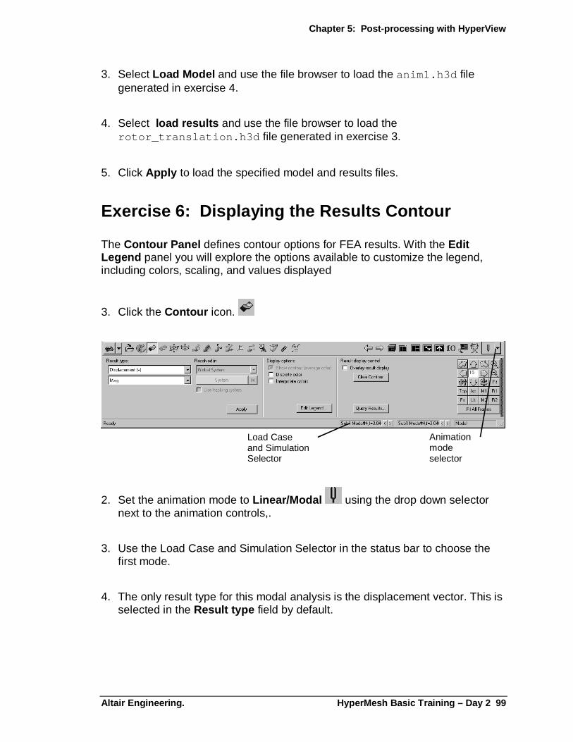
Chapter 5: Post-processing with HyperView
Altair Engineering. HyperMesh Basic Training – Day 2 99
3. Select Load Model and use the file browser to load the anim1.h3d file generated in exercise 4.
4. Select load results and use the file browser to load the rotor_translation.h3d file generated in exercise 3.
5. Click Apply to load the specified model and results files.
Exercise 6: Displaying the Results Contour
The Contour Panel defines contour options for FEA results. With the Edit Legend panel you will explore the options available to customize the legend, including colors, scaling, and values displayed
3. Click the Contour icon.
Animationmodeselector
Load Caseand SimulationSelector
2. Set the animation mode to Linear/Modal using the drop down selector next to the animation controls,.
3. Use the Load Case and Simulation Selector in the status bar to choose the first mode.
4. The only result type for this modal analysis is the displacement vector. This is selected in the Result type field by default.
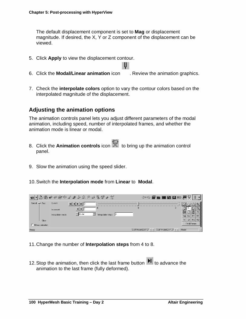
Chapter 5: Post-processing with HyperView
100 HyperMesh Basic Training – Day 2 Altair Engine ering
The default displacement component is set to Mag or displacement magnitude. If desired, the X, Y or Z component of the displacement can be viewed.
5. Click Apply to view the displacement contour.
6. Click the Modal/Linear animation icon . Review the animation graphics.
7. Check the interpolate colors option to vary the contour colors based on the interpolated magnitude of the displacement.
Adjusting the animation options The animation controls panel lets you adjust different parameters of the modal animation, including speed, number of interpolated frames, and whether the animation mode is linear or modal.
8. Click the Animation controls icon to bring up the animation control panel.
9. Slow the animation using the speed slider.
10. Switch the Interpolation mode from Linear to Modal .
11. Change the number of Interpolation steps from 4 to 8.
12. Stop the animation, then click the last frame button to advance the animation to the last frame (fully deformed).
Chapter 5: Post-processing with HyperView
Altair Engineering. HyperMesh Basic Training – Day 2 101
Additional contour options
13. Go back to the contour panel .
14. Check the discrete color option. Notice that the color contour is shown as discrete color bands. Uncheck this option to view the blended contour.
The Query Results… sub panel allows you to identify the result value at a specific node or element. The results at the selected entity are displayed in table.
15. Click the Query Results… button to bring up the sub panel.
16. With the yellow Nodes selector active, pick on one of the red nodes in the model.
17. The node id is displayed, along with value of the data type and simulation.
18. Select several additional nodes in the model.
19. Click Return to go back to the contour panel.
Editing the contour legend The contour legend can be fully user defined, from the number of levels and colors, to the numeric format. A customized legend can be saved to a legend file and retrieved into other HyperView sessions. Also, the customized settings can be set in the prefrences.mvw file, which is read upon startup.
20. Click the Edit Legend… button in the center of the panel to bring up the Edit legend window.
Chapter 5: Post-processing with HyperView
102 HyperMesh Basic Training – Day 2 Altair Engine ering
The Legend Type: options allow you to switch between a fixed scale or dynamic scale. The dynamic scale option will vary the legend scale for each time step when viewing transient results. This does not apply to linear/modal results such as the file we are working with.
The Position options allow you to choose which corner of the window will display the legend.
21. Use the Numeric format selector to change from Scientific to Fixed .
The Numeric precision value defines how many numbers are displayed after the decimal point for each value in the legend.
The Number of levels selector allows you to control how many increments are in the legend.
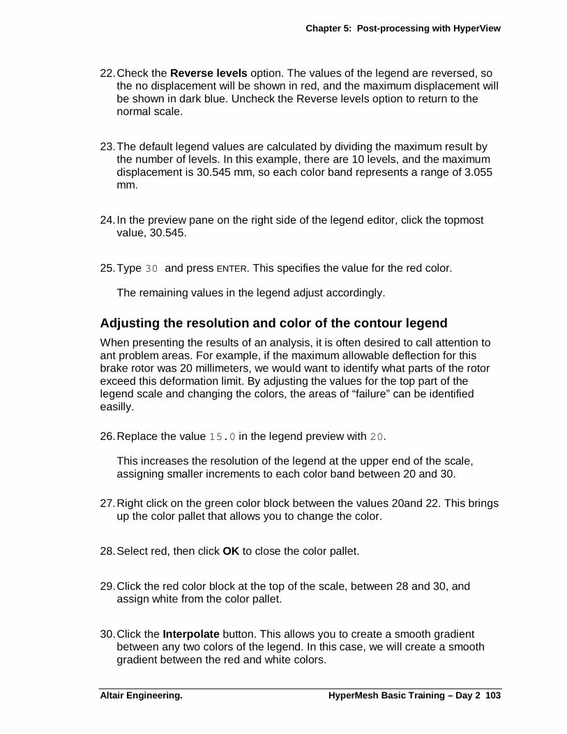
Chapter 5: Post-processing with HyperView
Altair Engineering. HyperMesh Basic Training – Day 2 103
22. Check the Reverse levels option. The values of the legend are reversed, so the no displacement will be shown in red, and the maximum displacement will be shown in dark blue. Uncheck the Reverse levels option to return to the normal scale.
23. The default legend values are calculated by dividing the maximum result by the number of levels. In this example, there are 10 levels, and the maximum displacement is 30.545 mm, so each color band represents a range of 3.055 mm.
24. In the preview pane on the right side of the legend editor, click the topmost value, 30.545.
25. Type 30 and press ENTER. This specifies the value for the red color.
The remaining values in the legend adjust accordingly.
Adjusting the resolution and color of the contour l egend When presenting the results of an analysis, it is often desired to call attention to ant problem areas. For example, if the maximum allowable deflection for this brake rotor was 20 millimeters, we would want to identify what parts of the rotor exceed this deformation limit. By adjusting the values for the top part of the legend scale and changing the colors, the areas of “failure” can be identified easilly.
26. Replace the value 15.0 in the legend preview with 20 .
This increases the resolution of the legend at the upper end of the scale, assigning smaller increments to each color band between 20 and 30.
27. Right click on the green color block between the values 20and 22. This brings up the color pallet that allows you to change the color.
28. Select red, then click OK to close the color pallet.
29. Click the red color block at the top of the scale, between 28 and 30, and assign white from the color pallet.
30. Click the Interpolate button. This allows you to create a smooth gradient between any two colors of the legend. In this case, we will create a smooth gradient between the red and white colors.
Chapter 5: Post-processing with HyperView
104 HyperMesh Basic Training – Day 2 Altair Engine ering
31. Note the message in the lower left of the legend edit panel “Select the first color to interpolate”.
32. Click the white color band in the legend preview. The message changes to “Select second color to interpolate”
33. Pick the red color band. The top five color bands now show a smooth gradient from red to white.
34. In the Edit legend panel, there are text fields for Header and Footer . Click the checkbox to turn on these fields, then enter any text desired for the header or footer in the appropriate field. Use the font dialog (A button) to set the text attributes. Note the checkboxes that allow you to turn on or off the Title or Minimum/Maximum in the legend.
35. Click OK to close the Legend Preview and apply the changes to the contour plot.
Exercise 7: Reviewing the Deformed Shape
In the Deformed Shape panel you can display the undeformed and deformed shape of the model determined by the results applied in the contour panel. The deformation of the model can be scaled up to exaggerate very small deformations, or scaled down to de-emphasize large deformations.
1. Click the Deformed icon.
2. Start the animation
Chapter 5: Post-processing with HyperView
Altair Engineering. HyperMesh Basic Training – Day 2 105
Set the deformation scale
Scale: has three options, each of which can be set to uniform or component values.
• Scale factor : Scales the displacement units by multiplying the results by the value specified.
• Model percent : The maximum displacement will be scaled to the specified percentage of the bounding box that contains all model geometry.
• Model units : The maximum displacement in the results will be set to the number of model units defined, and all other results will be scaled accordingly
3. Select Scale Factor .
The default Scale factor is Uniform 1.00 .
4. Click Apply .
5. Under Undeformed shape select Show: Features then click Apply .
6. The Color selector for the undeformed shape has three choices: Component, Mesh lines and User. Select User , then click on the color button to set the color using the color pallet.
7. Set the Scale Factor to 2.00 . Click Apply .
This multiplies the deformation of the model by 2.
There are two options to the Interpolation : Linear and Modal . Select Linear .
Linear mode cycles from undeformed to fully deformed in a number of steps, then jumps back to the undeformed shape. Modal interpolation cycles smoothly from undeformed to deformed, back to undeformed, then deformed in the opposite direction, simulating the free vibration deformations of the part.
8. Set the Interpolation steps to: 12
9. Use a Displacement: Scale Factor of 1.000 .
10. Click Apply .
Chapter 5: Post-processing with HyperView
106 HyperMesh Basic Training – Day 2 Altair Engine ering
11. Set Interpolation Mode to Modal .
12. Click Apply to observe the differences in the interpolation modes.
13. Stop the animation
Exercise 8: Saving the H3D file
The Export File dialog allows you to save the current model as a H3D file to be used in HyperView Player. You can also read H3D files back into the animation window.
1. Click the Export File button, , on the animation toolbar to display the Export File dialog.
2. Select the folder to save the file to in the Save in: box.
3. Assign the name as_displayed.h3d to the session file in the file name box.
4. Save as Type should be set to H3D File (*.h3d).
5. The As Displayed option is selected as default.
6. Click Save.
7. Click the File option from the Menu .
8. Select Export H3D Models… from the drop down list.
9. Assign the name compressed.h3d to the session file in the file name box
10. Save as Type should be set to H3D File (*.h3d).
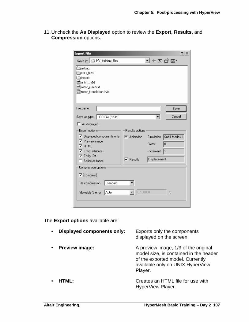
Chapter 5: Post-processing with HyperView
Altair Engineering. HyperMesh Basic Training – Day 2 107
11. Uncheck the As Displayed option to review the Export, Results, and Compression options.
The Export options available are:
• Displayed components only : Exports only the components displayed on the screen.
• Preview image : A preview image, 1/3 of the original model size, is contained in the header of the exported model. Currently available only on UNIX HyperView Player.
• HTML: Creates an HTML file for use with HyperView Player.

Chapter 5: Post-processing with HyperView
108 HyperMesh Basic Training – Day 2 Altair Engine ering
• Entity attributes : Outputs specific attributes assigned to the model's entities, such as color, transparency, etc. If deselected, the default attributes will be used when the file is loaded.
• Entity IDs : Exports entity ID’s.
• Solids as faces : Writes out solids as faces and does not output faces that are obscured. Warning: If solids are written out as faces, contouring of elemental values on solids is impossible.
The available Results Options are:
• Animation : Exports the file with the current animation settings.
• Results : If selected, result values are exported with the model. If not selected, only the model and animation are exported.
The available Compression Options are:
• Compress : Allows you to compress the size of the file before exporting. From the File compression drop-down menu, select standard or high compression. Standard compression compresses the model by a significant amount. High compression compresses the model more than standard does, but it takes longer to write the file.
• Allowable % error : Indicates the suggested amount that the model's values can be perturbed when compressed. You can use the default setting by selecting auto, or select user-defined and enter a value for the allowable % error. The value you provide will be compared to the results of an error estimation function to allow the program's compression algorithm to maintain an acceptable level of accuracy for your data. However, even a percentage of zero may result in some loss due to minute rounding errors.
12. Check the Compress option. Set the File compression to Standard . Leave the Allowable % error to Auto
Chapter 5: Post-processing with HyperView
Altair Engineering. HyperMesh Basic Training – Day 2 109
13. Click Save.
Check the size of the newly generated h3D files using the windows explorer. The two files as_displayed.h3d and compressed.h3d differ now by a significant amount in their file size.
Exercise 9: Reviewing Multiple Modes
HyperView allows you to create multiple pages in the same session, and up to 16 windows per page. In this exercise, add 3 additional animation windows and review 4 normal modes simultaneously.
1. Click the Page Layout icon, and select the 4-window layout.
2. Click Close to close the Page Layout window.
3. Click in the upper right window to make it active.
4. Select the Load Model icon from the Client Tool Bar .
5. Check the Load model option and use the file browser to load any one of the files containing model information.
6. Check the Load results option and use the file browser to load any one of the files containing results information.
The summary table from the beginning of this chapter is reproduced here:
File name Contents Source
Rotor_translation.h3d Model and results Generated by hmnasto2
Rotor_run.res Hm results format Generated by OptiStruct
Rotor_run.op2 Results in op2 format Generated by OptiStruct
Rotor_run.fem Model file Input file to OptiStruct
Anim1.h3d Model file Generated by HyperMesh
7. Click Apply to load the specified model and results files
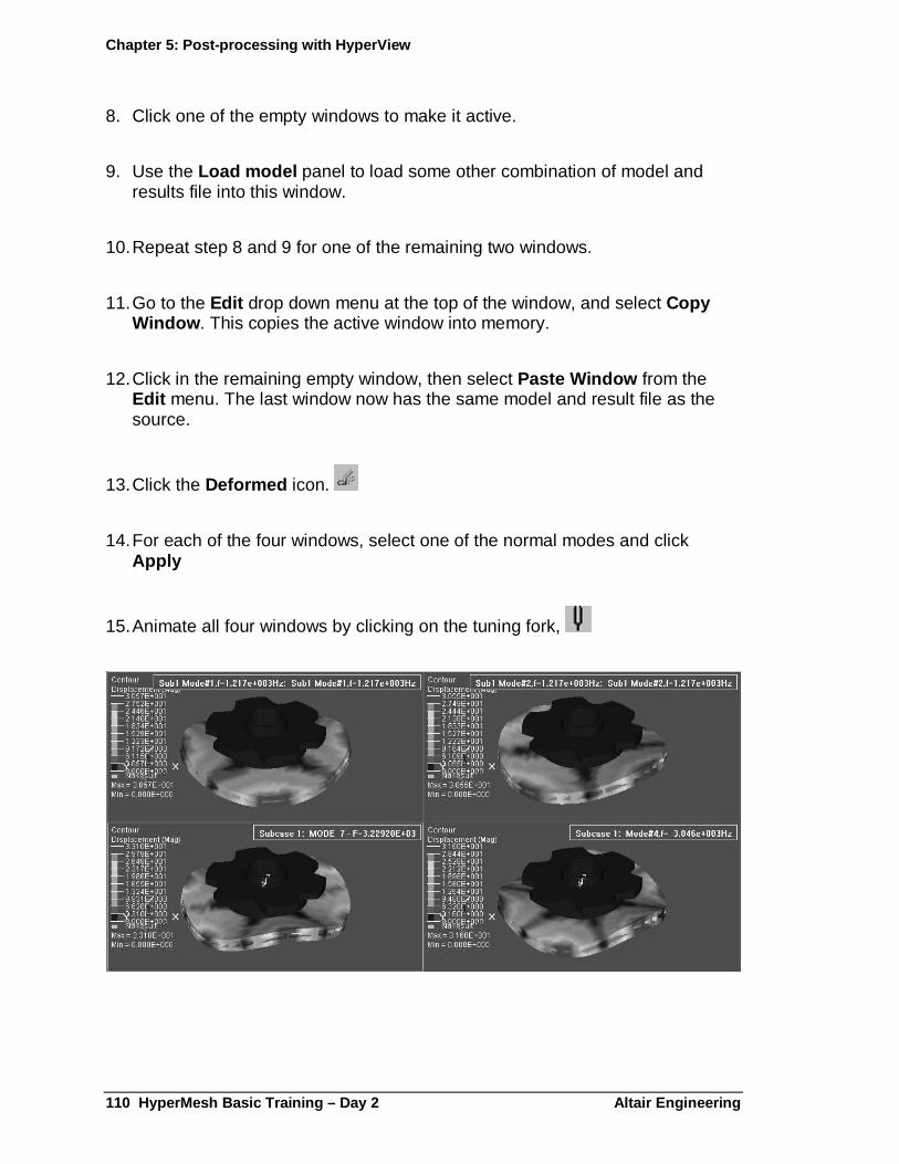
Chapter 5: Post-processing with HyperView
110 HyperMesh Basic Training – Day 2 Altair Engine ering
8. Click one of the empty windows to make it active.
9. Use the Load model panel to load some other combination of model and results file into this window.
10. Repeat step 8 and 9 for one of the remaining two windows.
11. Go to the Edit drop down menu at the top of the window, and select Copy Window . This copies the active window into memory.
12. Click in the remaining empty window, then select Paste Window from the Edit menu. The last window now has the same model and result file as the source.
13. Click the Deformed icon.
14. For each of the four windows, select one of the normal modes and click Apply
15. Animate all four windows by clicking on the tuning fork,

Chapter 5: Post-processing with HyperView
Altair Engineering. HyperMesh Basic Training – Day 2 111
Summary:
In this chapter, four methods of generating H3D files were explored. First, a FORMAT card was added to an OptiStruct analysis to request additional output formats. Along with the H3D file generated from OptiStruct, the HTML report and embeded HyperViewPlayer were used to review the results.
Next, using the hmnasto2 results translator, the NASTRAN format output2 file was translated into an H3D format file. From within HyperMesh, a third H3D format file was generated, this time containing only the model and component information.
A fourth H3Dafter displaying the results contour and modifying the legend, a fourth H3D file was generated from HyperView with specific session attributes.
Finally, a multiple window page was created to review the deformations of four different natural frequency modes simultaneously.