Embed Size (px)
Citation preview
7/27/2019 Hz Drains Leech
http://slidepdf.com/reader/full/hz-drains-leech 1/13
Open Pit Slope Depressurization using Horizontal Drains – a Case Study
Simon Leech a), Matthew McGann b)
a)PT Newmont Nusa Tenggara, Geotechnical and Hydrogeological Dept., Jl. Sriwijaya # 258 Mataram
83126, Indonesia email: [email protected] tel +62 8175749564b)PT Newmont Nusa Tenggara, Mine Water Management Dept., Jl. Sriwijaya # 258 Mataram 83126,
Indonesia email: [email protected] tel: +62 81917141081
Abstract The establishment of appropriate open pit slope design criteria evolves throughout the life of a mine, and isbased primarily on an ever increasing understanding of the rockmass conditions, including groundwater andassociated groundwater pressures that may be acting within the slopes. It has been highlighted over the pastdecade, that geotechnical engineering has not advanced significantly with respect to the integrated tools that areavailable to assist in the optimization of large open pit slopes, but it has long been realised that the reduction of groundwater related pore pressures, is an important component in the determination of whether a design can orhas been successfully achieved. Therefore, it is essential to implement an extensive multidisciplinary technicalprogram, incorporating mine, geotechnical and hydrogeological engineering expertise sourced both internal and
external to the mining operation.An integrated mine dewatering and slope depressurization program is necessary to increase the likelihood thatmine plans can be achieved, and at an acceptable level of risk. How much slope depressurization is appropriatein a large open pit environment is difficult to quantify, and often a philosophy of “more must be better” has tobe adopted due to the lack of integrated modelling tools that are available to assist in the optimization of theslope design. The slope designers often work in isolation of, or in parallel with hydrogeologists, whereas,ideally technically sound hydrogeological models need to be made available to slope designers well in advance.Scheduling pressures often require that results are needed within unrealistic time frames often leading to a“silver bullet” approach, primarily revolving around the desire to numerically model problems, prior to therebeing a fundamental understanding of the potential issues. Programs that lead to the establishment of reliablehydrogeological models in a relatively complex hard rock mining environment often take years to develop andmust be sustained and improved upon so that relatively reliable predictions can be made, as to what the futurehydrogeological conditions may be.
This paper presents a discussion of the on-going horizontal drain construction program at Batu Hijau, includinghow this is integrated with the operation of the mine, aspects of drilling related productivity, summaryeconomics and a review of the results achieved. Also discussed is the value of appropriately installedgroundwater monitoring infrastructure, which has allowed the results of the program to be quantified and hasprovided site specific data to allow for on-going optimisation. The program to date has had its challenges, buthas been largely successful, with results confirming the benefit of installing horizontal drains in the right placeand at the right time.
Key words: horizontal drain, slope stability, open pit, Vibrating Wire Piezometer, Indonesia.
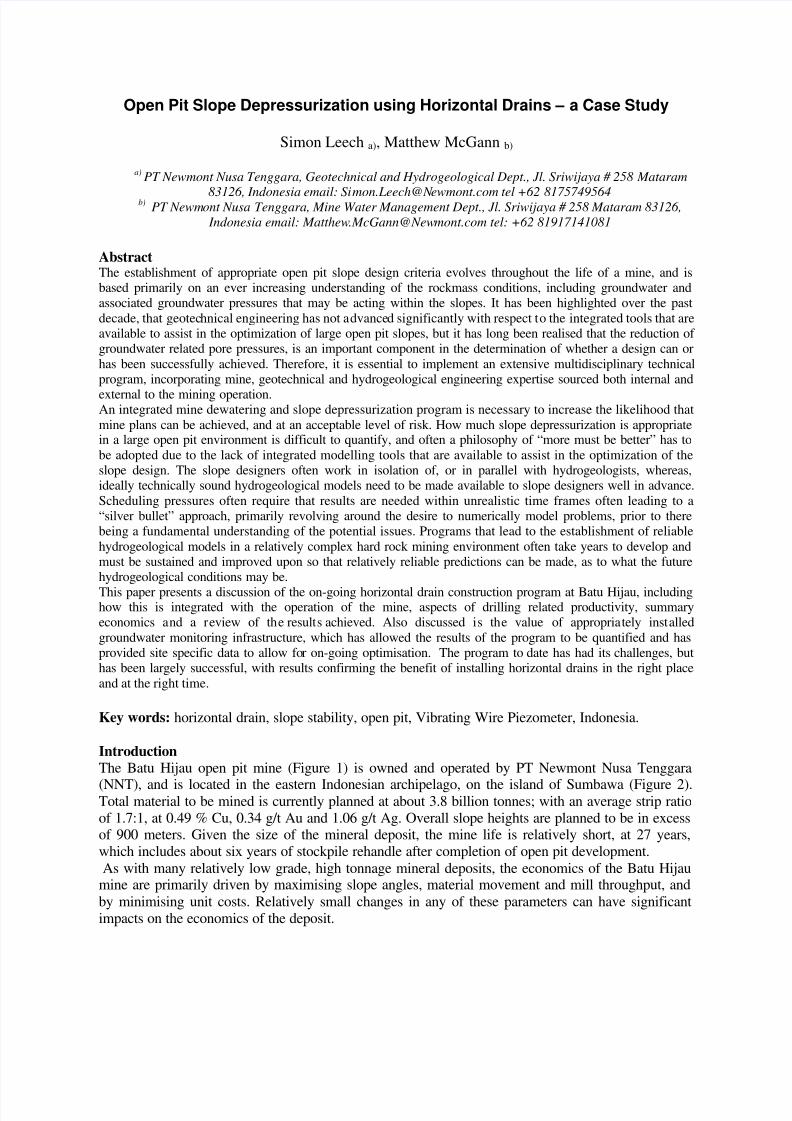
IntroductionThe Batu Hijau open pit mine (Figure 1) is owned and operated by PT Newmont Nusa Tenggara
(NNT), and is located in the eastern Indonesian archipelago, on the island of Sumbawa (Figure 2).Total material to be mined is currently planned at about 3.8 billion tonnes; with an average strip ratioof 1.7:1, at 0.49 % Cu, 0.34 g/t Au and 1.06 g/t Ag. Overall slope heights are planned to be in excessof 900 meters. Given the size of the mineral deposit, the mine life is relatively short, at 27 years,which includes about six years of stockpile rehandle after completion of open pit development.As with many relatively low grade, high tonnage mineral deposits, the economics of the Batu Hijau
mine are primarily driven by maximising slope angles, material movement and mill throughput, andby minimising unit costs. Relatively small changes in any of these parameters can have significantimpacts on the economics of the deposit.
7/27/2019 Hz Drains Leech
http://slidepdf.com/reader/full/hz-drains-leech 2/13
Figure 1 Satellite image of the Batu Hijau mine as at June 2007
Figure 2 Location of the Batu Hijau mine within the eastern Indonesian archipelago
7/27/2019 Hz Drains Leech
http://slidepdf.com/reader/full/hz-drains-leech 3/13
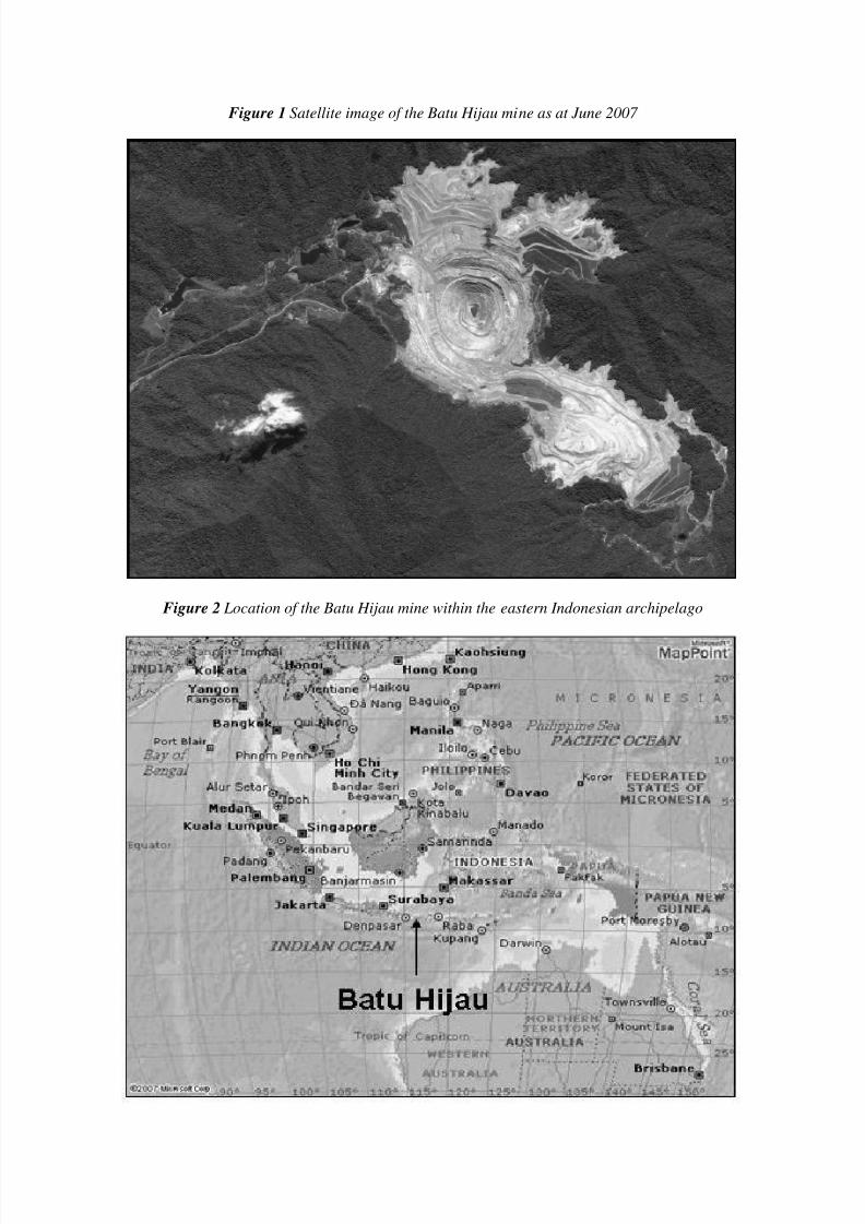
BackgroundNNT was formed in 1985 for the purpose of carrying out systematic exploration for epithermal goldmineralisation on the islands of Lombok and Sumbawa. A Contract of Work was granted by theGovernment of Indonesia in 1986. Surface exploration led to the discovery of porphyry copper-goldmineralisation at Batu Hijau in 1990, with further work up to 1996 leading to the delineation of adeposit.The Government of Indonesia approved the Batu Hijau Project feasibility study in May 1997, atwhich time construction permits were granted. Pre-stripping of the open pit began in October 1997,with the mill process commissioned late in 1999.At Batu Hijau the climate is seasonal, subject to a ‘wet’ monsoon from October to April and a ‘dry’monsoon from May to September. About 85% of the 2,500 millimetre annual rainfall occurs duringthe wet season. Typically rainfall events are of relatively short duration, but of high intensity.The country rock in the area of Batu Hijau consists of andesite volcanics, volcaniclastic sedimentsand porphyritic andesite (Figure 3). In the north-eastern area of the mine this sequence was intrudedby a quartz diorite. Multiple tonalite porphyries were intruded along the contact between thevolcanics and diorite, with the majority of mineralisation associated with earlier tonalite intrusionsand higher intensity of quartz veining. As part of the mineralization process the basic lithology has
been overprinted by extensive hydrothermal alteration.On a district scale there are two major fault zones, the northeast trending Bambu-Santong andnorthwest trending Tongoloka-Batu Hijau Fault Corridor. The two intersect three kilometresnorthwest of the centre of the deposit. Major faults that transect the open pit are those associated withthe Tongoloka-Batu Hijau Fault Corridor, with discrete faults spaced at about 50 meters. There is alsoa less persistent orthogonal fault set.
Figure 3 Simplified geology of the Batu Hijau deposit
7/27/2019 Hz Drains Leech
http://slidepdf.com/reader/full/hz-drains-leech 4/13
HydrogeogeologyAt Batu Hijau the pre-mining groundwater level in and surrounding the mineral deposit was typicallya subdued reflection of the topography. The steep gradients suggested that formation permeabilitywas low and typically in the 1x10⁻⁶ to 1x10⁻⁸ meters per second range, but with some preferential flowpaths providing for relatively rapid drain-down following recharge events. Although a number of fault zones were identified prior to the initiation of dewatering operations within the open pit, theirinfluence on groundwater flows were not well understood.The on-going hydrogeological characterisation program at Batu Hijau has lead to a continuedrefinement of the conceptual groundwater flow model, which in general terms is as follows:
Recharge in the deposit area is derived primarily from rainfall with minimal regionalgroundwater through-flows.
Deposit permeability is greatest within the orebody and reduces radially from the centre of the mineral deposit.
Deposit porosity is low and is estimated to be in the 0.1% to 0.5% range.
Weathering of the upper 100-150 meters of the host or country rock has resulted in reducedpermeability nearer to the deposit surface.
South-westerly, shallowly dipping faults in the southern sector of the deposit provide abarrier to lateral groundwater flow with heads in this area not impacted by open pitdewatering operations.
Permeability along the northwest trending Tongoloka-Batu Hijau Fault Corridor is enhanced.
As additional geological, geotechnical and hydrogeological information becomes available thehydrogeological model for Batu Hijau will continue to be updated and refined.
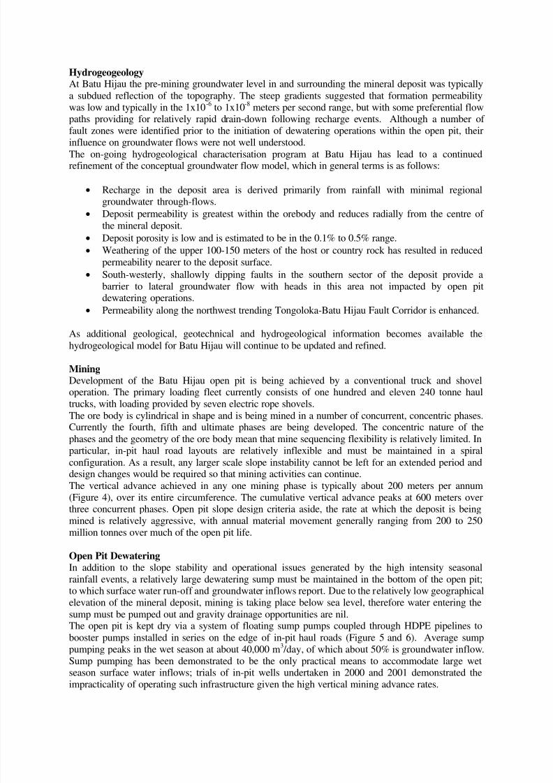
MiningDevelopment of the Batu Hijau open pit is being achieved by a conventional truck and shoveloperation. The primary loading fleet currently consists of one hundred and eleven 240 tonne haultrucks, with loading provided by seven electric rope shovels.The ore body is cylindrical in shape and is being mined in a number of concurrent, concentric phases.Currently the fourth, fifth and ultimate phases are being developed. The concentric nature of thephases and the geometry of the ore body mean that mine sequencing flexibility is relatively limited. Inparticular, in-pit haul road layouts are relatively inflexible and must be maintained in a spiralconfiguration. As a result, any larger scale slope instability cannot be left for an extended period anddesign changes would be required so that mining activities can continue.The vertical advance achieved in any one mining phase is typically about 200 meters per annum(Figure 4), over its entire circumference. The cumulative vertical advance peaks at 600 meters overthree concurrent phases. Open pit slope design criteria aside, the rate at which the deposit is beingmined is relatively aggressive, with annual material movement generally ranging from 200 to 250million tonnes over much of the open pit life.
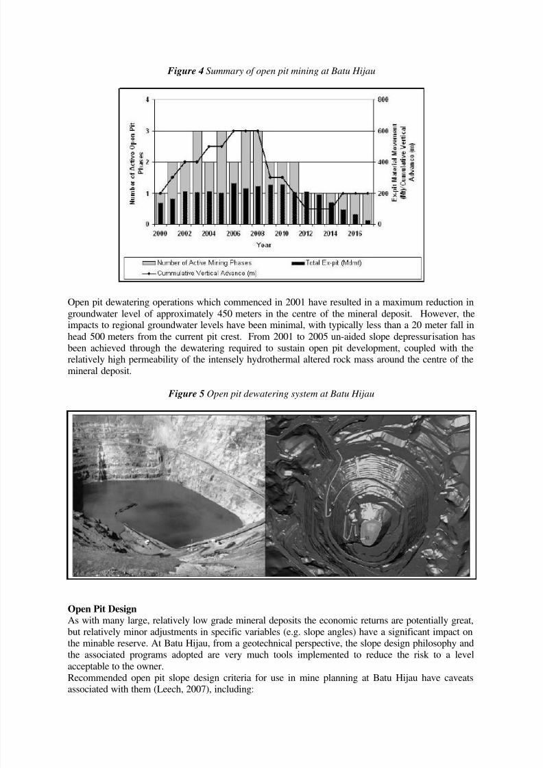
Open Pit DewateringIn addition to the slope stability and operational issues generated by the high intensity seasonalrainfall events, a relatively large dewatering sump must be maintained in the bottom of the open pit;to which surface water run-off and groundwater inflows report. Due to the relatively low geographicalelevation of the mineral deposit, mining is taking place below sea level, therefore water entering thesump must be pumped out and gravity drainage opportunities are nil.The open pit is kept dry via a system of floating sump pumps coupled through HDPE pipelines tobooster pumps installed in series on the edge of in-pit haul roads (Figure 5 and 6). Average sumppumping peaks in the wet season at about 40,000 m3 /day, of which about 50% is groundwater inflow.Sump pumping has been demonstrated to be the only practical means to accommodate large wetseason surface water inflows; trials of in-pit wells undertaken in 2000 and 2001 demonstrated the
impracticality of operating such infrastructure given the high vertical mining advance rates.
7/27/2019 Hz Drains Leech
http://slidepdf.com/reader/full/hz-drains-leech 5/13
Figure 4 Summary of open pit mining at Batu Hijau
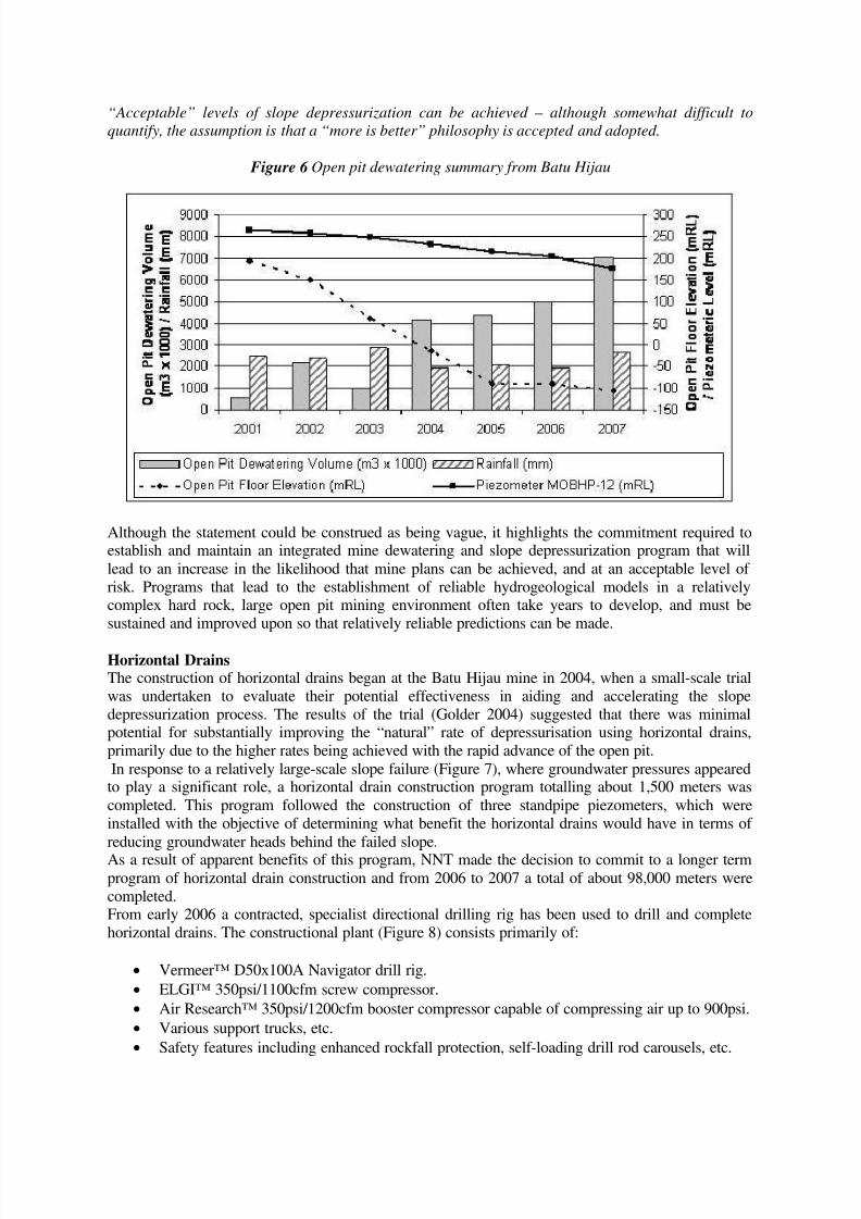
Open pit dewatering operations which commenced in 2001 have resulted in a maximum reduction ingroundwater level of approximately 450 meters in the centre of the mineral deposit. However, theimpacts to regional groundwater levels have been minimal, with typically less than a 20 meter fall inhead 500 meters from the current pit crest. From 2001 to 2005 un-aided slope depressurisation hasbeen achieved through the dewatering required to sustain open pit development, coupled with therelatively high permeability of the intensely hydrothermal altered rock mass around the centre of themineral deposit.
Figure 5 Open pit dewatering system at Batu Hijau
Open Pit DesignAs with many large, relatively low grade mineral deposits the economic returns are potentially great,but relatively minor adjustments in specific variables (e.g. slope angles) have a significant impact onthe minable reserve. At Batu Hijau, from a geotechnical perspective, the slope design philosophy andthe associated programs adopted are very much tools implemented to reduce the risk to a levelacceptable to the owner.Recommended open pit slope design criteria for use in mine planning at Batu Hijau have caveatsassociated with them (Leech, 2007), including:
7/27/2019 Hz Drains Leech
http://slidepdf.com/reader/full/hz-drains-leech 6/13
“Acceptable” levels of slope depressurization can be achieved – although somewhat difficult to
quantify, the assumption is that a “more is better” philosophy is accepted and adopted.
Figure 6 Open pit dewatering summary from Batu Hijau
Although the statement could be construed as being vague, it highlights the commitment required toestablish and maintain an integrated mine dewatering and slope depressurization program that willlead to an increase in the likelihood that mine plans can be achieved, and at an acceptable level of risk. Programs that lead to the establishment of reliable hydrogeological models in a relativelycomplex hard rock, large open pit mining environment often take years to develop, and must besustained and improved upon so that relatively reliable predictions can be made.
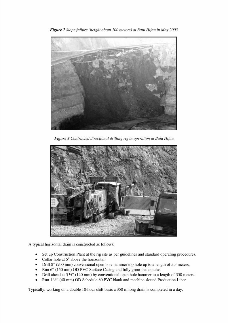
Horizontal DrainsThe construction of horizontal drains began at the Batu Hijau mine in 2004, when a small-scale trialwas undertaken to evaluate their potential effectiveness in aiding and accelerating the slopedepressurization process. The results of the trial (Golder 2004) suggested that there was minimalpotential for substantially improving the “natural” rate of depressurisation using horizontal drains,primarily due to the higher rates being achieved with the rapid advance of the open pit.In response to a relatively large-scale slope failure (Figure 7), where groundwater pressures appearedto play a significant role, a horizontal drain construction program totalling about 1,500 meters wascompleted. This program followed the construction of three standpipe piezometers, which wereinstalled with the objective of determining what benefit the horizontal drains would have in terms of reducing groundwater heads behind the failed slope.
As a result of apparent benefits of this program, NNT made the decision to commit to a longer termprogram of horizontal drain construction and from 2006 to 2007 a total of about 98,000 meters werecompleted.From early 2006 a contracted, specialist directional drilling rig has been used to drill and completehorizontal drains. The constructional plant (Figure 8) consists primarily of:
Vermeer™ D50x100A Navigator drill rig.
ELGI™ 350psi/1100cfm screw compressor.
Air Research™ 350psi/1200cfm booster compressor capable of compressing air up to 900psi.
Various support trucks, etc.
Safety features including enhanced rockfall protection, self-loading drill rod carousels, etc.
7/27/2019 Hz Drains Leech
http://slidepdf.com/reader/full/hz-drains-leech 7/13
Figure 7 Slope failure (height about 100 meters) at Batu Hijau in May 2005
Figure 8 Contracted directional drilling rig in operation at Batu Hijau
A typical horizontal drain is constructed as follows:
Set up Construction Plant at the rig site as per guidelines and standard operating procedures.
Collar hole at 5o above the horizontal.
Drill 8” (200 mm) conventional open hole hammer top hole up to a length of 5.5 meters.
Run 6” (150 mm) OD PVC Surface Casing and fully grout the annulus.
Drill ahead at 5 ½” (140 mm) by conventional open hole hammer to a length of 350 meters.
Run 1 ½” (40 mm) OD Schedule 80 PVC blank and machine slotted Production Liner.
Typically, working on a double 10-hour shift basis a 350 m long drain is completed in a day.
7/27/2019 Hz Drains Leech
http://slidepdf.com/reader/full/hz-drains-leech 8/13
Over the 2006 to 2007 period the total average cost per meter of horizontal drain constructed wasabout US$44, comprising:
Direct contractor costs (drilling, running casing/liner, work time, rig moves, etc) US$37.
Diesel fuel US$2.
Construction consumables and materials (casing, liner, grout, etc) US$5.
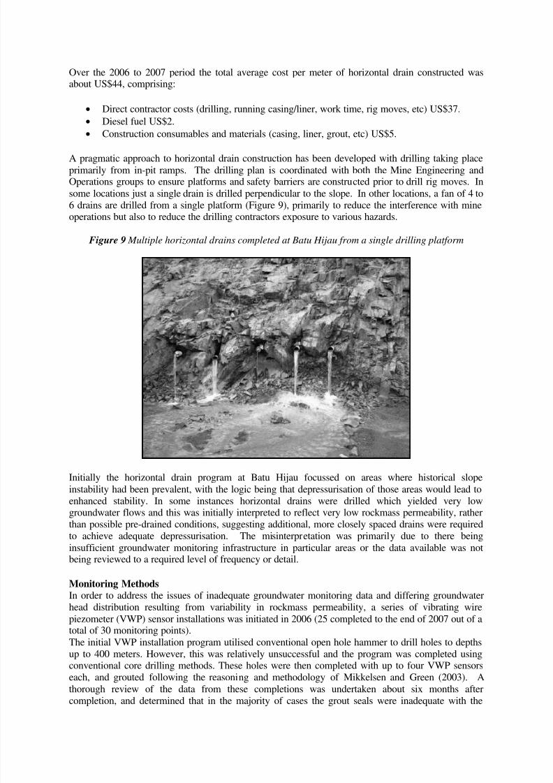
A pragmatic approach to horizontal drain construction has been developed with drilling taking placeprimarily from in-pit ramps. The drilling plan is coordinated with both the Mine Engineering andOperations groups to ensure platforms and safety barriers are constructed prior to drill rig moves. Insome locations just a single drain is drilled perpendicular to the slope. In other locations, a fan of 4 to6 drains are drilled from a single platform (Figure 9), primarily to reduce the interference with mineoperations but also to reduce the drilling contractors exposure to various hazards.
Figure 9 Multiple horizontal drains completed at Batu Hijau from a single drilling platform
Initially the horizontal drain program at Batu Hijau focussed on areas where historical slopeinstability had been prevalent, with the logic being that depressurisation of those areas would lead toenhanced stability. In some instances horizontal drains were drilled which yielded very lowgroundwater flows and this was initially interpreted to reflect very low rockmass permeability, ratherthan possible pre-drained conditions, suggesting additional, more closely spaced drains were requiredto achieve adequate depressurisation. The misinterpretation was primarily due to there being
insufficient groundwater monitoring infrastructure in particular areas or the data available was notbeing reviewed to a required level of frequency or detail.
Monitoring MethodsIn order to address the issues of inadequate groundwater monitoring data and differing groundwaterhead distribution resulting from variability in rockmass permeability, a series of vibrating wirepiezometer (VWP) sensor installations was initiated in 2006 (25 completed to the end of 2007 out of atotal of 30 monitoring points).The initial VWP installation program utilised conventional open hole hammer to drill holes to depthsup to 400 meters. However, this was relatively unsuccessful and the program was completed usingconventional core drilling methods. These holes were then completed with up to four VWP sensorseach, and grouted following the reasoning and methodology of Mikkelsen and Green (2003). A
thorough review of the data from these completions was undertaken about six months aftercompletion, and determined that in the majority of cases the grout seals were inadequate with the
7/27/2019 Hz Drains Leech
http://slidepdf.com/reader/full/hz-drains-leech 9/13
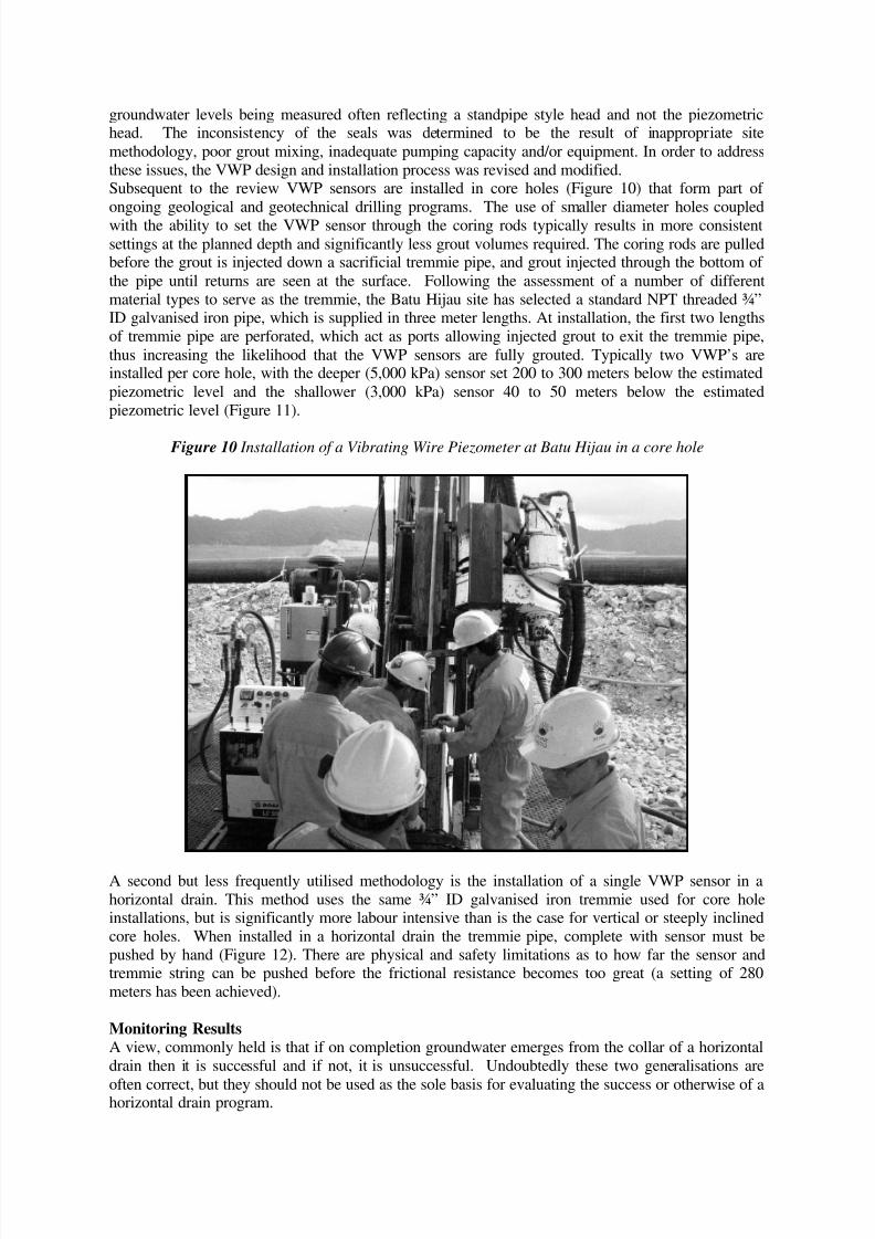
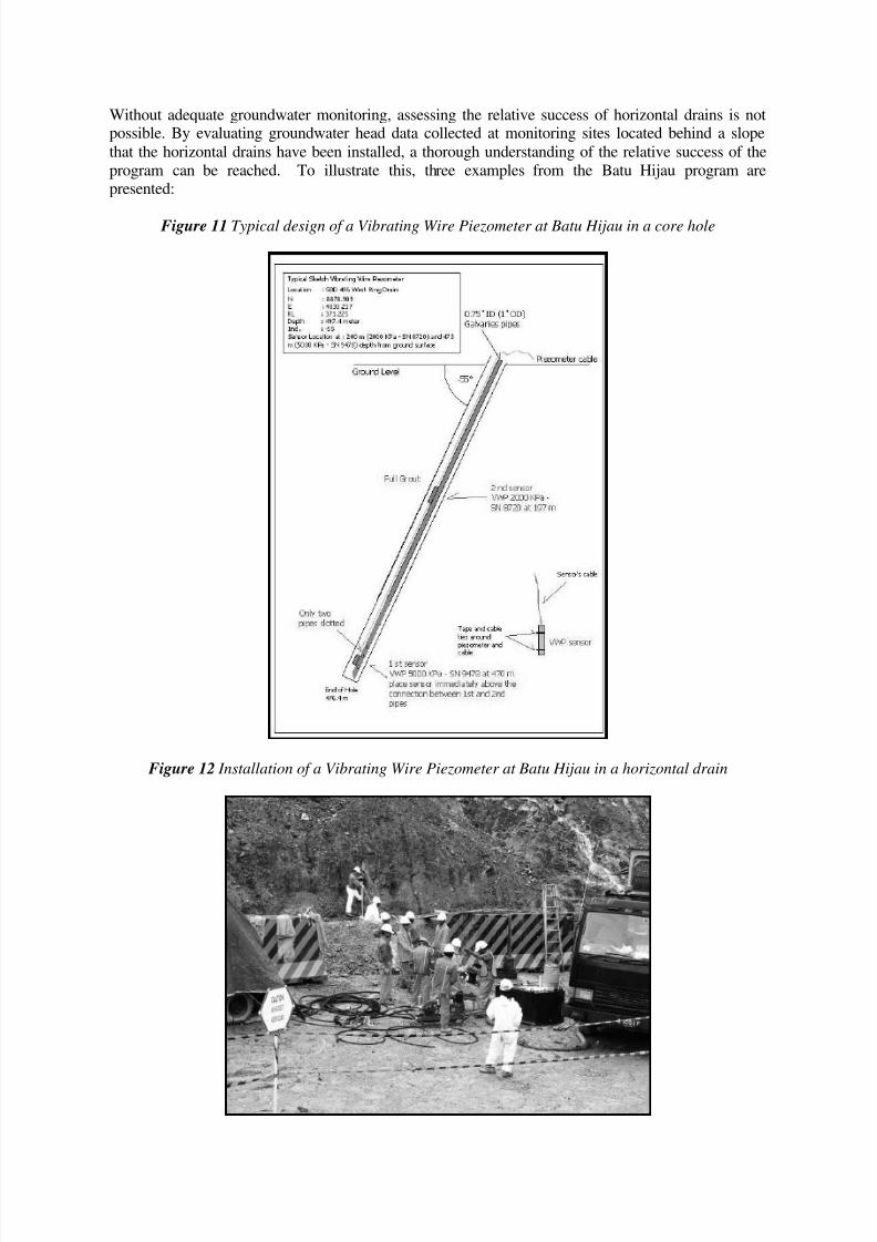
groundwater levels being measured often reflecting a standpipe style head and not the piezometrichead. The inconsistency of the seals was determined to be the result of inappropriate sitemethodology, poor grout mixing, inadequate pumping capacity and/or equipment. In order to addressthese issues, the VWP design and installation process was revised and modified.Subsequent to the review VWP sensors are installed in core holes (Figure 10) that form part of ongoing geological and geotechnical drilling programs. The use of smaller diameter holes coupledwith the ability to set the VWP sensor through the coring rods typically results in more consistentsettings at the planned depth and significantly less grout volumes required. The coring rods are pulledbefore the grout is injected down a sacrificial tremmie pipe, and grout injected through the bottom of the pipe until returns are seen at the surface. Following the assessment of a number of differentmaterial types to serve as the tremmie, the Batu Hijau site has selected a standard NPT threaded ¾”ID galvanised iron pipe, which is supplied in three meter lengths. At installation, the first two lengthsof tremmie pipe are perforated, which act as ports allowing injected grout to exit the tremmie pipe,thus increasing the likelihood that the VWP sensors are fully grouted. Typically two VWP’s areinstalled per core hole, with the deeper (5,000 kPa) sensor set 200 to 300 meters below the estimatedpiezometric level and the shallower (3,000 kPa) sensor 40 to 50 meters below the estimatedpiezometric level (Figure 11).
Figure 10 Installation of a Vibrating Wire Piezometer at Batu Hijau in a core hole
A second but less frequently utilised methodology is the installation of a single VWP sensor in ahorizontal drain. This method uses the same ¾” ID galvanised iron tremmie used for core holeinstallations, but is significantly more labour intensive than is the case for vertical or steeply inclinedcore holes. When installed in a horizontal drain the tremmie pipe, complete with sensor must bepushed by hand (Figure 12). There are physical and safety limitations as to how far the sensor andtremmie string can be pushed before the frictional resistance becomes too great (a setting of 280meters has been achieved).
Monitoring ResultsA view, commonly held is that if on completion groundwater emerges from the collar of a horizontaldrain then it is successful and if not, it is unsuccessful. Undoubtedly these two generalisations are
often correct, but they should not be used as the sole basis for evaluating the success or otherwise of ahorizontal drain program.
7/27/2019 Hz Drains Leech
http://slidepdf.com/reader/full/hz-drains-leech 10/13
Without adequate groundwater monitoring, assessing the relative success of horizontal drains is notpossible. By evaluating groundwater head data collected at monitoring sites located behind a slopethat the horizontal drains have been installed, a thorough understanding of the relative success of theprogram can be reached. To illustrate this, three examples from the Batu Hijau program arepresented:
Figure 11 Typical design of a Vibrating Wire Piezometer at Batu Hijau in a core hole
Figure 12 Installation of a Vibrating Wire Piezometer at Batu Hijau in a horizontal drain
7/27/2019 Hz Drains Leech
http://slidepdf.com/reader/full/hz-drains-leech 11/13
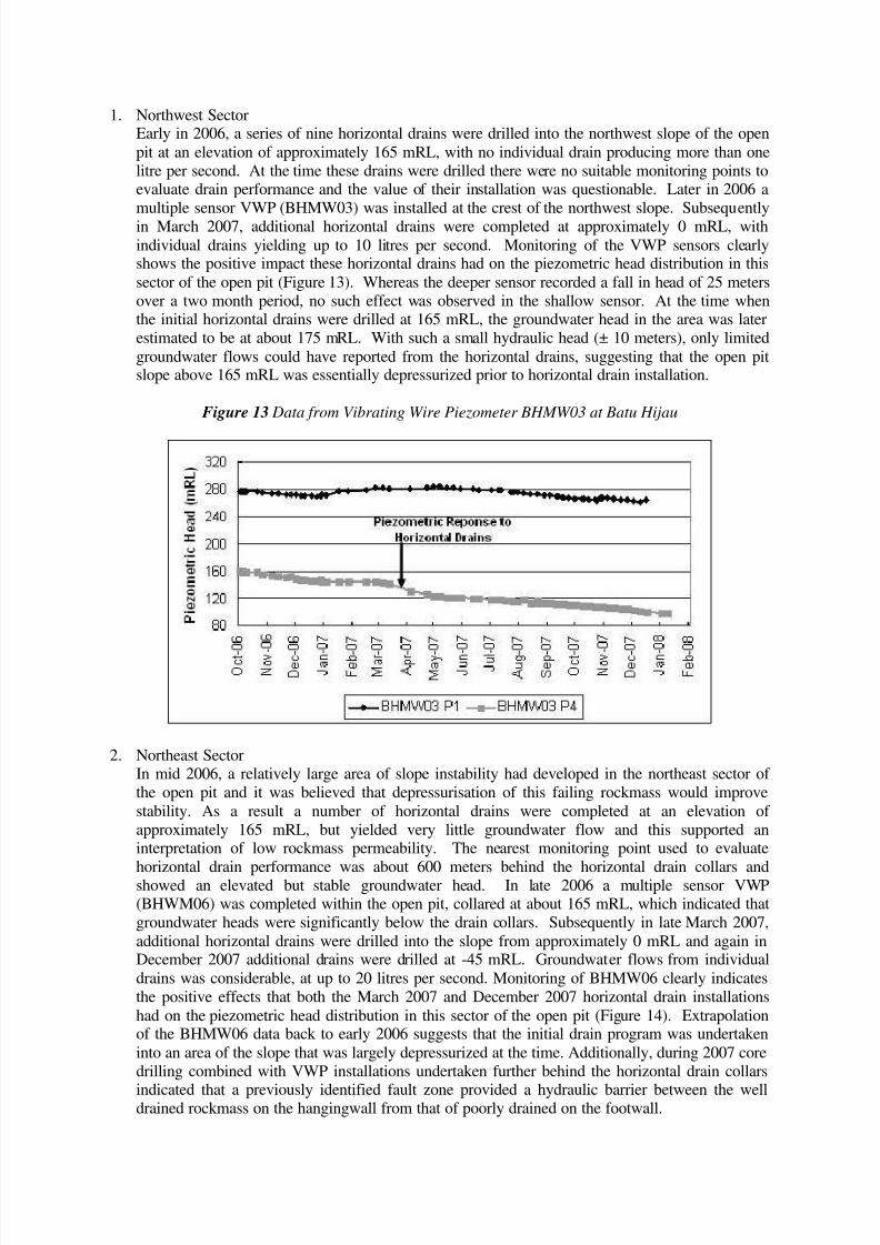
1. Northwest SectorEarly in 2006, a series of nine horizontal drains were drilled into the northwest slope of the openpit at an elevation of approximately 165 mRL, with no individual drain producing more than onelitre per second. At the time these drains were drilled there were no suitable monitoring points toevaluate drain performance and the value of their installation was questionable. Later in 2006 amultiple sensor VWP (BHMW03) was installed at the crest of the northwest slope. Subsequentlyin March 2007, additional horizontal drains were completed at approximately 0 mRL, withindividual drains yielding up to 10 litres per second. Monitoring of the VWP sensors clearlyshows the positive impact these horizontal drains had on the piezometric head distribution in thissector of the open pit (Figure 13). Whereas the deeper sensor recorded a fall in head of 25 metersover a two month period, no such effect was observed in the shallow sensor. At the time whenthe initial horizontal drains were drilled at 165 mRL, the groundwater head in the area was laterestimated to be at about 175 mRL. With such a small hydraulic head (± 10 meters), only limitedgroundwater flows could have reported from the horizontal drains, suggesting that the open pitslope above 165 mRL was essentially depressurized prior to horizontal drain installation.
Figure 13 Data from Vibrating Wire Piezometer BHMW03 at Batu Hijau
2. Northeast SectorIn mid 2006, a relatively large area of slope instability had developed in the northeast sector of the open pit and it was believed that depressurisation of this failing rockmass would improvestability. As a result a number of horizontal drains were completed at an elevation of approximately 165 mRL, but yielded very little groundwater flow and this supported aninterpretation of low rockmass permeability. The nearest monitoring point used to evaluate
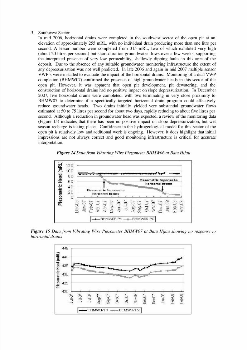
horizontal drain performance was about 600 meters behind the horizontal drain collars andshowed an elevated but stable groundwater head. In late 2006 a multiple sensor VWP(BHWM06) was completed within the open pit, collared at about 165 mRL, which indicated thatgroundwater heads were significantly below the drain collars. Subsequently in late March 2007,additional horizontal drains were drilled into the slope from approximately 0 mRL and again inDecember 2007 additional drains were drilled at -45 mRL. Groundwater flows from individualdrains was considerable, at up to 20 litres per second. Monitoring of BHMW06 clearly indicatesthe positive effects that both the March 2007 and December 2007 horizontal drain installationshad on the piezometric head distribution in this sector of the open pit (Figure 14). Extrapolationof the BHMW06 data back to early 2006 suggests that the initial drain program was undertakeninto an area of the slope that was largely depressurized at the time. Additionally, during 2007 coredrilling combined with VWP installations undertaken further behind the horizontal drain collars
indicated that a previously identified fault zone provided a hydraulic barrier between the welldrained rockmass on the hangingwall from that of poorly drained on the footwall.
7/27/2019 Hz Drains Leech
http://slidepdf.com/reader/full/hz-drains-leech 12/13
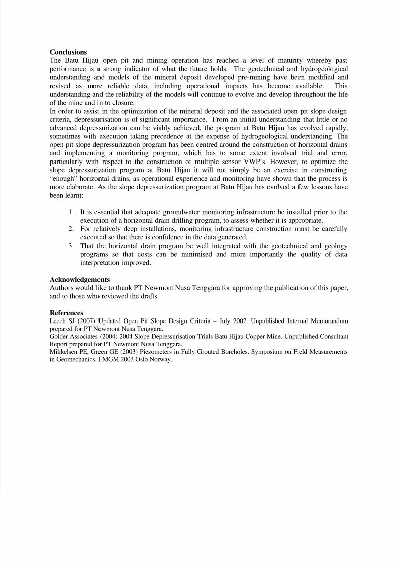
3. Southwest Sector In mid 2006, horizontal drains were completed in the southwest sector of the open pit at anelevation of approximately 255 mRL, with no individual drain producing more than one litre persecond. A lesser number were completed from 315 mRL, two of which exhibited very high(about 20 litres per second) but short duration groundwater flows over a few weeks, supportingthe interpreted presence of very low permeability, shallowly dipping faults in this area of thedeposit. Due to the absence of any suitable groundwater monitoring infrastructure the extent of any depressurisation was not well predicted. In late 2006 and again in mid 2007 multiple sensorVWP’s were installed to evaluate the impact of the horizontal drains. Monitoring of a dual VWPcompletion (BHMW07) confirmed the presence of high groundwater heads in this sector of theopen pit. However, it was apparent that open pit development, pit dewatering, and theconstruction of horizontal drains had no positive impact on slope depressurization. In December2007, five horizontal drains were completed, with two terminating in very close proximity toBHMW07 to determine if a specifically targeted horizontal drain program could effectivelyreduce groundwater heads. Two drains initially yielded very substantial groundwater flowsestimated at 50 to 75 litres per second for about two days, rapidly reducing to about five litres persecond. Although a reduction in groundwater head was expected, a review of the monitoring data
(Figure 15) indicates that there has been no positive impact on slope depressurization, but wetseason recharge is taking place. Confidence in the hydrogeological model for this sector of theopen pit is relatively low and additional work is ongoing. However, it does highlight that initialimpressions are not always correct and good monitoring infrastructure is critical for accurateinterpretation.
Figure 14 Data from Vibrating Wire Piezometer BHMW06 at Batu Hijau
Figure 15 Data from Vibrating Wire Piezometer BHMW07 at Batu Hijau showing no response to
horizontal drains
7/27/2019 Hz Drains Leech
http://slidepdf.com/reader/full/hz-drains-leech 13/13
ConclusionsThe Batu Hijau open pit and mining operation has reached a level of maturity whereby pastperformance is a strong indicator of what the future holds. The geotechnical and hydrogeologicalunderstanding and models of the mineral deposit developed pre-mining have been modified andrevised as more reliable data, including operational impacts has become available. Thisunderstanding and the reliability of the models will continue to evolve and develop throughout the lifeof the mine and in to closure.In order to assist in the optimization of the mineral deposit and the associated open pit slope designcriteria, depressurisation is of significant importance. From an initial understanding that little or noadvanced depressurization can be viably achieved, the program at Batu Hijau has evolved rapidly,sometimes with execution taking precedence at the expense of hydrogeological understanding. Theopen pit slope depressurization program has been centred around the construction of horizontal drainsand implementing a monitoring program, which has to some extent involved trial and error,particularly with respect to the construction of multiple sensor VWP’s. However, to optimize theslope depressurization program at Batu Hijau it will not simply be an exercise in constructing“enough” horizontal drains, as operational experience and monitoring have shown that the process ismore elaborate. As the slope depressurization program at Batu Hijau has evolved a few lessons have
been learnt:
1. It is essential that adequate groundwater monitoring infrastructure be installed prior to theexecution of a horizontal drain drilling program, to assess whether it is appropriate.
2. For relatively deep installations, monitoring infrastructure construction must be carefullyexecuted so that there is confidence in the data generated.
3. That the horizontal drain program be well integrated with the geotechnical and geologyprograms so that costs can be minimised and more importantly the quality of datainterpretation improved.
Acknowledgements Authors would like to thank PT Newmont Nusa Tenggara for approving the publication of this paper,
and to those who reviewed the drafts.
ReferencesLeech SJ (2007) Updated Open Pit Slope Design Criteria – July 2007. Unpublished Internal Memorandumprepared for PT Newmont Nusa Tenggara.Golder Associates (2004) 2004 Slope Depressurisation Trials Batu Hijau Copper Mine. Unpublished ConsultantReport prepared for PT Newmont Nusa Tenggara.Mikkelsen PE, Green GE (2003) Piezometers in Fully Grouted Boreholes. Symposium on Field Measurementsin Geomechanics, FMGM 2003 Oslo Norway.