Embed Size (px)
Citation preview

I 1 Care and Maintenance
Dust pro tec tion is provided by a fle xible dust cove r which should always be used when the instrument is not in use The stand should be cleaned from time to time with a linen or leashyther cloth alcohol must nol be used as it altacks the paint but pe troleum is well suited for c leaning the pa inted surfaces Pale spots on the object stage can be re moved by ru bbing with parafshyfin oi l or vaseline Particular care should be taken when undertaking studies using acids or o the r aggressive chemi ca ls Direct contact of these substances with the stand or optics must be avoided under all circumstances and all parts should be carefully cleaned aft e r use The o pti cs must be kept scrupul ously c lean Dust ca n be removed from glass surfaces by means of a drygt fine-haired brush blowing gently across the surface whilst brushing I f the din is difficult to remove a clean cloth moisshytened with distilled water can be used or if trus also has no e ffect pure a lcoho l may be applied Pa rti cular care should be taken when clea ning anti~ref1ection coatings The outer eye shypiece surfaces and the front elements of the objecti ves ha ve coatings o f approximately the same hardness as glass and must be correspondingly carefully clea ned Objecti ves should not be screwed apart during cleaning If damage or dirt is no ticed inside the m they should be re turned to us for repair Cleaning of the inner surfaces of the eyepieces is also advi sed against Microscopes being used in hot andlor humid cJima tes require special care It should be ensured that a build-up of fungu s does not occu r which is managed in the first place by thoshyrough and meticulous cleaning and storage in a cupboard whose inside temperature is at least 5 OC above tha t o f the roo m It must also be provided with ai ring holes loosely plugged with cotton woo l or gauze as protection aga inst dust If this type of storage is not possible the microscope must be
kept in a closed container with an adequa te amount o f drying agent (eg sil ica gel) These measures should be taken even in laborato ries with air conditioning In warm and dry climates) dust is the greatest enem y The instrument should there fore be cove red with the dust cover immediate ly after use o r clea nshying and stored in a cupboard If a humid period of lon ger than one month occurs storage in a warm cupboard as described above is desirable Proper handling of the mi croscope will ensure decades of se rshyvice If however a check over or re pair becomes necessary please contact yo ur Le itz agency or our Technica l Service direct
Technical Service Ernst Leitz Wetzlr GmbH postrch 2007 D-6330 Wetzlr West Germny Telex 483727 eltsc
2
3
Fig 1 Leitz LABORLUX S with stage no 11 condenser no 56 and binocular tube S
1 Eyepiece 2 Binocular lube S 45deg 3 Analyser slit 4 Objectives 5 Specimen stage no 11 6 Coaxial drive for moving the specimen
8 Height adjustment of the co ndense r mount 9 Condenser mount with slide changer
7 Screws to attach object gu id e no 12
10 Adjustable height stop of the conde nse r mount 11 Centring screws fo r condenser mo unt 12 Condenser no 56 13 Field di aph ragm
15 Mains switch (concealed) 14 Lamphousing 20
4
2 Assembling the microscope
Mounting the lubes
Press the lever in the direction of the arrow (Fig 2) the tube can DOW be inserted into the quick-change mount Once the tube has been inserted allow the lever to slide back The tube can be ro tated by 3600 and clamped in any position by slightly pulling the lever
Fig 2 M ounting the tubes
Inserting the eyepieces
The eyepieces are inserted into the eyepiece tubes (Fig 3) For the LABOR LU X S Leitz eyepieces are used which are calcushylated for the mechanical tube length of 160 mm Th ese eyeshypieces are dist inguished from those for 170 rum tube length by the additional identification ofthe fi e ld of view index after the magnification eg JOx20 If Lei tz eyepieces without this idenshytiflcation ofthe fie ld of view index are to be used a spacer ring (order no 519653) must be pushed over the eyepiece mount on the side of the tube
Fig 3 Inserting the eyepieces
The total magnification of the microscope is given by reproduction ratio of the objective x eyepiece magnifi cation (x tube facto r)
Example 25050 objective IOx18 eyepi ece tube fact or Ix Total magnificatio n 25 x 10 x 1 =250x
Screwing in the objectives
Screw the objectives into the nosepiece (Fig 4) in such a way that stepwise magnifica tion change is possible (eg in the order 4 10 40 etc) All Leitz microscope object ives from a magnification of 25x and calcu lated for a tu be length of160 mm ca n be used on th e Lei tz LAB ORLUX S Please no te in th is cootext the field iUushymjnation capacity of the condensers Microscope objectives calcul ated for 170 mm tube length ca n be used from 16x magnifica tion
Fig 4 Screw ing in the objectives
I 5
6
Identification markings on the objectives (Fig 5)
1 Mechanical tube length
The distance in mm from the objective shoulder to the edge of the tube
2 Cover glass
The engraving 017 is the thickness o f the coverglass A dash (-) instead of a number indi cates that the objective can be used for specimens with or without a coverglass
3 Field Oatness of the objective
EF objectives are systems with a more or less flat fi e ld of view of up to 18 mm intermediate image diameter PLAN objectives are systems with a flattened fi e ld of view up to 225 mm intermedia te image diameter
Fig 5 Objective identification
If there is no indication of field fl attening the objective is an achromat with optimum correction for use with up to 18 field of view index
4 Reproduction sca le in the intermediate image
Size ratio between the intermediate image and the object eg 10 1
5 Numerical aperture
Physical identification of the object ives resolving power
6 Immersion medium
Immersion media can be for example oil water (W) or glycershyine (GLYC) The objective must always be used with the engraved immersion medium Before the immersion objective is focused a drop of immershysion medium should be applied to the object without air bubbles
7 Phase cootrast objectives
Objectives with phase ring for phase contrast observa tion These objectives have green writing (with the exception of achromats with black sleeves) The labe l for the condensershyside annular stops necessary for these objectives (eg PHACO 3) in a slide or in the turret platc of tbe UKL phase contrast condenser (eg PHACO 3= set turret plate to 3) is also to be found on the phase contrast objectives
8 Col oured ring indicating the objective magnification
9 Immersi on objectives
Allaehing Ihe objeel guide
The o bjecl guide no 12 for left- o r right-hand operation is allached to the left or right of the specimen stage with two screws (6l)
Inserting the condensers
Rotate the condenser clamp (2) until the dots on the knurled knob and on the condenser mount coincide Then lower lhe condenser USing the knob (71) until the conde nser (76)ca n be easily pushed into the mount as far as the stop Now turn the co ndenser clamp in the direction orthe arrow The condenser is now firml y fi xed in the slide changer Condense rs LK and UKL are inserted in Ihe same way as condenser no 56 (ill usshyIra ted 76)
Fig 6 Attaching the object gu ide 1 Fixing screws for o bjec l guide no 12
-
Condenser no 56
With the twomiddotlens conden~e r nO 56 homogeneous illuminashyti on is pnsgtible for all object field s oro bjcctves from 4x magnishyficati on at fi eld of view index 20 with out addit ional swinging in and out of the front lens
Condense r no 56 works with the nume rical apertu re A 090 If oil cap no 512652 is screwed on the numerica l aperture can be ra ised to A 125 when Leitz immersion oil is applied between the conden ser and the specim en To screw the oil cap on the protective ring mu st be screwed ofT with a knurled ring
Fig 7 Inserting the condenser 1 Height adjustment of the condenser holder 2 Condenser clamp 3 Condenser holder 4 Ce ntring screws for condenser mount 5 Adjustable heigh t stop for the condenser holder 6 Condenser no S6
shy
7
8
The aperture diaphragm is adju sted with the lever There is a scale for reproducible setting of the condenser diaphragm The slit at the s ide is inte nded fo r the insertion of slides with annular stops for simple darkfieid or phase contrast illuminashytion These can only be taken out of condenser no 56 again aft er the lever has been presse d
Condenser LK The LK cond enser has a hinged condenser top S 11 When the con denser top isswung out the lower part of the cond eoser can illuminate aU object fi e lds of o bjecti ves from 25x upwards with field of view ind ex 20 When using objectives of lOx and higher the condenser top must be swung in This is done with the handle (82)
Fig 7b Condenser no 56 I Protective ring 2 Locking lever for fgthde with difTusion disc and annular stops 3 Slil ror slide with diffusion disc and annu lar stops 4 Lever for adju stment of aperture diaphragm 5 Dovetail guide
With condenser top A 090 S 11 swung in the condense r LK works with the numerical aperture A 090 The image of the field diaphragm is produced with the conde nser top S 11 in a glass medium 12 mm ove r the stage surface The condenser top of the LK cond enser is interchangeabl e via a thread with other condenser tops with a high er numerical ap~rlure or tops with a longer working distan ce Darkfield conshydenser tops D 080 or D 119 can also be screwe d on ins tead of the S 11 standard top Furth er information on condenser tops can be found in th e tabl e o n page 10 The ape rture iris diaphragm is adjus ted with th c lever (83) There is a scale for reproducible setting of the condenser diaphragm
Fig 8 Condenser LK t A 090 S Il Condenser top 2 Hltlndle to swing out the condenser top J Lever for adjustment of the il perture diaphrn gm
Condenser UKL
Its performance fea tures in brightfJeld are the same as those of the condenser no 56 The annular s lOPS necessary for phase contrast or darklield illushymination are situated in a turret plate (94) for quick chaoge Position H (93) of the turret is for brightfleld (Hellfeld) investigations Posit ions I 2 and 3 accommodate the ann ular SlOPS PHACO 1 2 and 3 These can be aligned to th e phase ring of the objective in li se by pushing in the two centring screws (9 2) Position 4 is occupied by an annular stop fo r darkfeJd wi th object ives from lOx to 40x The wheel (95) is for adjusting the aperture diaphragm on ly necessary for brightfield investigations It is fully opened for phase contrast or darkfield (PH position)
F ig 9 UKL condense r 1 Adj ustment telescope for ctntring the annular stops 2 Centring screws (press io to use) 3 Turret plate position indication 4 Tu rret plate 5 Adjust ment wheel wi th scale fo r apert ure diaphragm
Darkfield condensers 0080 and Dl9
The condenser D 080 is intended for darkfleld investigat ions with lOx to 40x objectives Image co ntras t is optimised he re as compared with the darkfieJd produced with annular stops The condenser D 119 has an oil imme rsion cap and is used toge ther with oil immersion object ives The darkfield condenshyser caps are also available without bottom parts and can be screwed onto the bottom part of th e LK condenser
Fig 10 Darkfield objective and funnel stop J Condensertop D 080 - 095 S I J 2 Oil condenser top D 1 19 - 144 3 Lower pari of condense r with dovetail guide 4 Special darkfield objecti ve EF 100 1 25 -060 Oel wilh built-in iri s
diaphragm 5 Knurled ring for adjustment oflhe iri s diaphragm 6 Funnel slop for the oil immersion objective
9
10
Condenser LK
Condenser Top
Top inoul Use
090 S 11 Out With objective ape rture lt025
090 S 11 In With objec tive aperture gt025
OEL 132 In (Immersion oil on front element)
With OEL 100132 objective
070 S 4 In Intercep t distance 4 mm With specimen slides of thicknessgt 1mm
055 S 15 In Intercep t distance 15 mm With specimen slides of thicknessgt 6 mm
DO80-095 Conde nser top in light path Darkfie ld With objective apertures lt075
D 119-144 Condenser top in light path (Immersion oi l on front element)
Darkfield With objective apertures lt 110
UKL ul)iversal condenser for phase contrast
Condenser Revolver Objective Application top setting with
engraving
090 S 11 H I 2 3 5
AU objectives PHACO I PHAC02 PHAC03 AU objectives with aperture lt 075
BrighLfield Phase contrast Phase contrast Phase contrast Darkfteld
Attaching the Imphousing 20
Lamphousing 20 is plugged into the guide sockets situated at the back of the stand and secured with the screw (111) (you may find it handy to use a coin) Then connect the microscope via the connecting socke t (112) with the mains cable to the mains The switch (lU) is For switching the illumination on and off The lamp intensity can be regulated with the knurled knob (114)
Fig It Attaching iamphollsing 20 1 Fixing screw 2 Connecting sockel ror mains cable 3 Onoff swilch 4 Intensity regulation
Changing the lamp
Press the lamp socke t (121) unlock by turning to the le ft and take it out of the lamp housing Remove the defect lamp When inserting the new lamp do not remo ve its protecti ve wrapping until the lamp is in position Return the lamp sock e t to the lamshyphollsing press in and lock in place by turning to the right
Fig 12 Changing the lamp I Lamp sockel 2 Intensi ty regulation
11
Operation of the microscope
Focusing the image
Place a specimen on the stage or slide it inla the mounting plate (131) if available Specimen stage no II (15) can be supplied with two clips to secure the specjmen Instead of these cl ips object guide no 12 can be attached to the left or right of the stage for left- or rightshyhanded operation (Fig 6) It bas an adjustment range of76x 26 mm Precise movement of the specime n wlthin a range of 76x 52111m is possible with the mechanical stage no 18 (Fig 13) The object guide no 12 and mechanical stage no 18 have a ve rshynier scale (1 32) for adjustment of both the x and the yaxis
Fig 13 Mechanical stage no 18 1Specimen mounting plate 2 Vernier scale
t2
This enables ce rtain parts o f the specimen to be set reprod ucshyibly
Turn in a medium-power objective eg EI 10025 by rotating the nosepiece Switch o n the illuminalion (113) and regul ate the intensity by turning knob (122) Turn the sc rew (75) by approx 5 ro tations to the left and use the height adjustment (71) to move the condense r to the upper stop near the specimen With the LK co ndenser the condenser lOp (8 1) is swung into lhe illumin a ting light path with the handle (82) [fyou change to objectives of less than lOx magnification afterwa rds swing the condenser to p o ut of lhe illumina ting li ght path Ope n the aperture diaphragm (83) and the fi e ld diaphragm (113)
Adjustment of the binocular tubes
If usi ng the binocular tubes adjust the interpupill ary distance until the images for both eyes comple tely cover each other and appear as a single circul ar image Then transfer the interpupil shylary distance (141) to theseales (142) of the two eyepiece tubes
How to compensate for vision defects Look through the right-h and eyepiece with your right eye and focus the specimen with the fin e drive Then watch the same part of tbe specimen wit h yo ur left eye a nd ro ta te the le ft-h and eyepiece tube until the same part of the object is in sharp foc us D o not use the fine drive for this This setti ng should be rechecked after centIation of the condenser
When us ing the binocular FSA o r FSA-R pb oto tubes (Fig 14) the tube length is automatically compensated when the eyeshypieces are set at the reqllired interpupillary di stance
The sy mbols on Lhe rotary knob of the binocular photo Lubes mean
100 light to the eyepieces
L 50 light to the eyepieces 50 to the pho to exit
10 light to the eyepieces 90 La the photo exit
The viewing angl e of the binocular SV and FSA-VR tubes ca n be adjusted by tilting Lhe front part of the tube between 0 and 40deg The user can thus set or alter the viewing height to suit himself
Fig 14 Selting the binonll ar Lube s
Centring (he condenser and setting the fieJd diaphragm
Focus the specimen using the coarse and fine drive
1 Close the fie ld diaphragm Loosen tbe stop screw and raise the condenser to its upperm ost position with the height adshyjustment (18)
2 Turn the condenser stop screw (114) to lower the condenser until the edges of the field diaphragm appea r sharp
3 Centre the image of the fi eld diaphragm wi th the two censhytering screws
4 Open the field diaphragm until i(just disappears from the field of view
Fig 15 Centering the condenser and se ll ing the field cliltlphrtlgm
13
14
Use of the field diaphlllgm
Ifoptimum contrast is to be attained it is important to illuminshyate only tbe part of the specimen that appears in the image Therefore the fi eld diaphragm is only opened as far as the field of view For this reason a change of magnification always necessitates matching the field diaphragm to the object field
Use of the aperture diapbragm
The more tbe aperture diaphragm is narrowed the higher the image contrast Axial resolving power (image sha rpness in the direction of the optical axis) also increases However excesshy~ive closure of the aperture diaphragm has an adverse effect on la teral resolving power (selectivity) The best optical pe rformance is obtained when the apertures of the objective and the condense r are the sa me A visible deterioration of resolving power is seen wben tbe aperture diapbragm is closed over 13 of the aperture of the objective and tbis s bould be avoided as far as possible To check this an eyepiece must be taken out of the eyepiece tube the aperture diaphragm narrowed until its image cove rs 113 of the illuminated rear lens area Replace the eyepiece If necessary the aperture diaphragm can be na rrowed further for objects with weak contrast Once determined the aperture diaphragm setting can be reproduced with the aid of the scales on the brightfield and phase contrast condensers
Note The aperture diaphragm should not be used to set image intenshysity This is done with the rotary knob (122) for regulat ion of lamp intensity or for photomicrography with neutral lightshyblocking filters
Oil immersion objectives
Oil immersioo objectives are labe lled with the additional e ngraving OEL and a black ring on the lower edge of the objective mount They must always be used with immersion oil Before the oil immersion objec tive is screwed into the nosepiece a drop of immersion oil must be applied to the specishymen Check that the immersion oil is free from air bubbles The immersion oil has almost the same refractive index ne= 1515 as the coverglass and the front lens of the microscope objective The focal length and th e working distance of an immersion objective are usually very small For this reason working with oil immersions requi res great ca re For routine work the ordinary 090 condenser is adequate even for oil immersions However if the full aperture of the immershysion objective is to be used eg for very fine structures the co ndenser aperture must also be enlarged For conden ser no 56 this ca n be done by screwing o n a 125 OEL condenser cap o r for the LK conde nser an APL OEL 132 S 11 co ndenser top In these cases immersio n o il must also be applied be tween the condenser captop and tbe underneath of the specimeo slide After the investigation aU surfaces where immersion oil has been applied must be carefu lly cleaned Use a soft clo th mois shytened with alcohol o r benzine
Transmitted light darklield with the LK condenser
For darkfield investigations condenser top D 080 - 095 IS
used when the objective has an aperture of less than 075 and condenser top D 119 - 144 when the objectives aperture is larshyger than 075 For apertures greater than lID insert a funnel stop into the oil immersion objective or use an objective with buill-in iris diaphragm Separate bottom parts are also available for the darkfield condenser tops which are pushed into the condenser mount instead of the brigblfield or phase contrast condensers
Focusing tbe darklield image (D 119 -144 and D 080 - 095)
Put a specimen o n the stage Turn the condenser stop screw to the right as far as the stop Insert the condenser and raise to the condenser stop If using the D 119 condenser top first apply a drop of imme rshysion oil to the surface of the condenser (taking care to avoid air bubbles) and then raise until the drop of oil touches the undershyneath of the specimen slid e This can be seen by a brief lighting up of the slide Bring the specimen inlo focus (Use Ihe 10 025 or 16040 objective) Close the field diaphragm Raise or lower the conshydenser by adjusting the condenser slop screw (110) to the left and using the co ndenser drive (18) until the edges ofthe diaphshyragm are as sharp as possible when the specimen is observed Move the image of the di aphragm into the centre of the field of view with the two centring screws (111) Open Ihe field diaphragm until it just disappears from the field of view
Phase contrast or darkfield illumination with condenser 00 56
Condenser no 56 can be fi tted with annular stop slid es DFI PHA CO for phase contrasl or dark field ill umination
- Centre the condenser with a brightfi eld specimen
- Screw in phase contrast objectives
- Open the aperture diaphragm
- Push the slide with the appropriate an nular stop (chart on page 16) into the condenser (Fig 16)
The DF155-56 annular st op slide is also avai lable for condenshyser no 56 with which simple darkfield illumination can be obtained using Objectives from lOx to 40x
Fig 16 Insertion of the slide with annular stop into condenser no 56
15
16
Annular stop
EF objectives PLAN objectives
I 10025 PHACO I PLAN 10025 PHACO I 2 25040 PHACO 2 PLAN 20040 PHACO I
40065 PHACO 2 PLAN 40065 PHAC02 3 1001125 PHACO 3 PLAN 1001125 OEL PHACO 3
Phase conlrlsl objectives Phase contrast with the UKL universal condenser
[nsert the UKL condenser into the condenser mount (19) and bring to its highest position with the vertical adjustment (18) Set the aperture diaphragm (95) to 10 (green) Put a specishyme n on the stage Turn in the 10025 PH ACO I objective Set the annu lar stop turret at position I and foc us (he specimen with the coarse and fine drive Cl ose the field diaphragm Set Ihe condenser with the vertical adjustment (18) so that the edges of the closed fi e ld diaphragm are in sharp foclis Centre the image of the field diaphragm with the two centdng screws Open the tield diaphragm until it just disappears from the field of view Remove an eyepiece from the eyepiece tube and insert the focusing telescope Loosen the clamp ring on the focusing telescope and adjust the eyelens until light and phase rings are in sharp focus Using the cenlring screws (press in and turn) adjust the light ring so that it is exactly covered by the phase ring of the objective Ce nlral ion must be cltIrried out o nce for all objectiveannular stop combina tions ltInd is then retained for all further settings
Fig 17 Phase ring and annular stop as seen through the fo cusing telescope
(]
Polarisation
Remove the protection piece from the analyser slit (181) and push the slide with the analyser (182) into the slit (181) Insert the filter holder into the field diaphragm mount so tha t the open part faces the user It should click into place Push the polariser (1) into the lower slit of the filter holder and turn until the fie ld of view observed without a specimen in place appears at its darkes t If desired a compensator ( or Al4 plate) (192) can be used in the second filter slit above the polarise r
Fig 18 Inserting the analyser
Fig 19 A rrangement or the poiariser I Polariser 2 Compensator 3 Holder
17
18
Incident light fluorescence
Assembly of Ihe equipmenl
Attach Ihe lamp hold er (2110) to Ihe upper pa rt of the stand with 2 Allen screws Unlock the o bselVatio n tube (2113) a nd re move fro m the stand Place the PLOEMOPAK (215) with light shield attached on the stand Push the light shield (2 19) into the lamp ho lde r Insert the observati on tub e int o the tube mount of the PLOEshyMOPAK This is done by pressing the lever (2L1 3) to the back and releasing once the lubus is in posi tion Attach the lamphou shysing (2111) to the lam p holder making sure that the clamping lever is in a vertica l position Clamp by turning the lever to the lel1 Remove the condenser and pu t th e light trap in its place (Fig 20)
Fig 20 lnserLing the light trap
Fig 21 Leitz LABORLUX S with I-Lambda PLOEMOPAK incident light flu orescence illuminator
I Groundglass screen fo r checking lamp cenlra tian 2 Orientation marks for co rrect insert ion of the fi lt er changi ng device 3 Locking mechanism of the fill er changi ng device 4 Fil ter changing device 5 1- PLOEMOPAK 6 Field diaphragm 7 Excitation light barrier 8 SO 38 red absorption filter 9 Light shield
10 Lamp holder for lamphollsing 102 Z II Lamphollsing 103 Z with 100 W mercury maximum-pressure lamp 12 Light trap 13 Lever for opening the tube mount
Q)~ ~reg
reg
19
20
Fig 23 Fig 22 Removed filler changing device with key for loosening tightening the Removing the- filler changing device to change the filter syste-m filler block
Fig 24 Loosening ti ghtening the filter block Fig 25 Inserting the filter block into the Jilter changing device The block When inserti ng the changi ng unit in to the housing it must be e nsured engrav in g (1) must be on the same side Cl5 the m arking (2) Iha t the two dOls (arrows) m e in line
Imiddot
21
22
Fig 26 3-lt PLOEMOPAK with lube fact or Ix I 3-lt PLOEMOPAK 2 Lever for changing the fille r sys tem 3 Lever sto p ro r the twin wavelength me thod 4 Field diaphragm 5 Excitation light barri er 6 SO 38 red absorp tion Cil ter 7 Lamphollsing mount 8 La mphousing 02 Z with lOOW me rcury maximum pressure lamp
Exchange and insertion of filter systems
Fig 27 Opening the cover to change a fill er sys tem The key for loosening and lightening the filler block Cltl n be found on Fig28 the inside of th e cover r1ate Looseningtigh teni ng the filter system
----~~
bullbull 1bull bull
shy fI
~
- J 23
24
Transmitled light insert
Instead ofa filter b lock a transmitted light insert can be used in the PLO EMOPAK for normal transmitted light microscopy The microscope can thus be used a lte rna te ly for transmitted light b righttie ld work and inc ident light n uoresce nce studies without the Leitz PLOEMOPAK having to he removed from the microscope
Fig 29 The arrowed number indicates the filter system In eITect The stop (t) clicks into place when the block is correct ly positioned Only fi lter blocks I and lcan now be used Fori nterchange between all th ree posimiddot tions pull the stop upwards and clamp by rota ting sligh tly
1 x
-bull
TWin wavelength method
This method is used for recognition of small amounts of one fluoro chrome in th e presence of relatively large quantities of a second By successive excitatio n with two wavelengths the specific nuorescence can be observed separately from the other Two differe nt components can then for example be recognised inside one or in separate cells
Please re fer to the instructions for the Lamphousing 103 Z (Order no 933 534) for information on insertio n ope ration and centratioD of the mercury maximum-pressure lamp
Filler blocks for lhe PLOEMOPAK incident-lighl iliumiDator
Splitting Absorption Order No Area of ExcitationName application mirror filterfilter Ultraviolet BP 270-380 RKP 380 BP410 -S80 513 597A2
RKP 400 LP 430 513596Ultraviole t BP 340- 380A RKP 455UV + viole t BP3S0-410 LP 470 513 599 B2 RKP 455 LP 460 513 600UV + viole t BP 355 - 425D
Blue BP 43617 RKP 475 LP 490 513601E3 RKP 510 LP SIS 513602UV + viole + blue BP 350- 460G
LP SISViolet + blue BP 420-490 RKP 510 513673H3 BP 450 - 490 RKP 510 LP SIS 513604Blue 1 213
513674Blue BP 470-490 RKP 510 LP SISK3 RKP 510 BP 525120 513 670Blue BP 450 - 490L3
Green BP 546114 RKP 580 LP 580 513608 M 2 RKP 580G reen BP 530- 560 LP 580 513 609N2
BP 515- 560 RKP 580 LP 580 513610GreenN 21
25
Fig 30 I Eye piece 2 Binocular lube S (30deg) J Lever to open the tube mount 4 Objecti ve 5 Mechanical s tage no 18 6 LK condenser 7 Coaxial drive for object movement 8 Coa rse and fine drive 9 fntensity regula tion for (he 6 V 20 W halogen lamp
10 Lamphollsing 104
26
27
4 Microscopic Measuring
The measurement of mi croscopi c o bjec ts is carried o ut using a measuring eyepiece (usual scale O mm = lOa divisions) Befo re starting the measurement the micrometer value orthe objective in use must be known Th e mi crometer valu e is the distance in the specimen plane which produces an image exactly one division lo ng on the graticule scale in the measurshying eyepi ece As the optical constants of the objectives fluctushyate sl ightly it is recommended that the micrometer value be determined initially wit h the aid of a specimen micrometer Examples Evaluation of the mic(ometer value with a specimen microshymeter (2 mm = 200 divis ions) and a measuring eyepiece with gra ticule (10 mm = 100 di visions)
Fig 32 Graticule sca le in (he eyep iece and specimen micr0meter im age
Move the micro mete r until the zero lines on both it and the measuring eyepiece coincide the micrometer valu e can be read off fro m the end of the measuring ey epiece scal e In this example the end of the eyepiece scale (lOa divisions) co incides with 1220 mm on (he micrometer scale 100 divisions therefore is equivalen t to 1220 mm and I division = 001220 mm = 1220 )1m For low-power objectives where the micrometer scale does not cover lhe entire eyepiece scale only 10 eyepiece scaledivisions ari measured For example irthe tenth division corresponds to 036 mm on the micrometer scale then 1 divisio n =
0036 mm = 36 )1m
For very precise measurements the screw micrometer eyeshypiece is available further details from brochure 51317
~ WILD LEITZ Wild Leitz GmbH 0 -6330 Wetzlar Optics precision eogineering electrooics Tel (0644 1) 29-0 Telex 483849 leiz d Telefax (064 41) 2933 99
Ordcl ~ )S of tile edltlOlls m Englisb German French Spanish hta u 9lJ 62 1 933620 933622 933623 933 624
- rcglsterrrll rlde mark Oesi lU ~ nu ~(lltdli oll1ms subjecl tO aHeral~n without nOlice
PaII middotNoS I2middotD6 rmhol n WcI middot( intl~llY IIQO[)XlHe
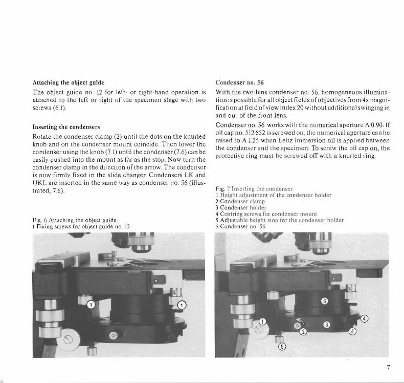
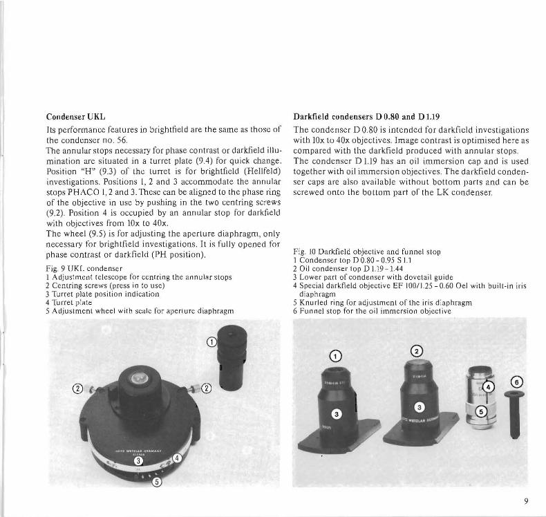
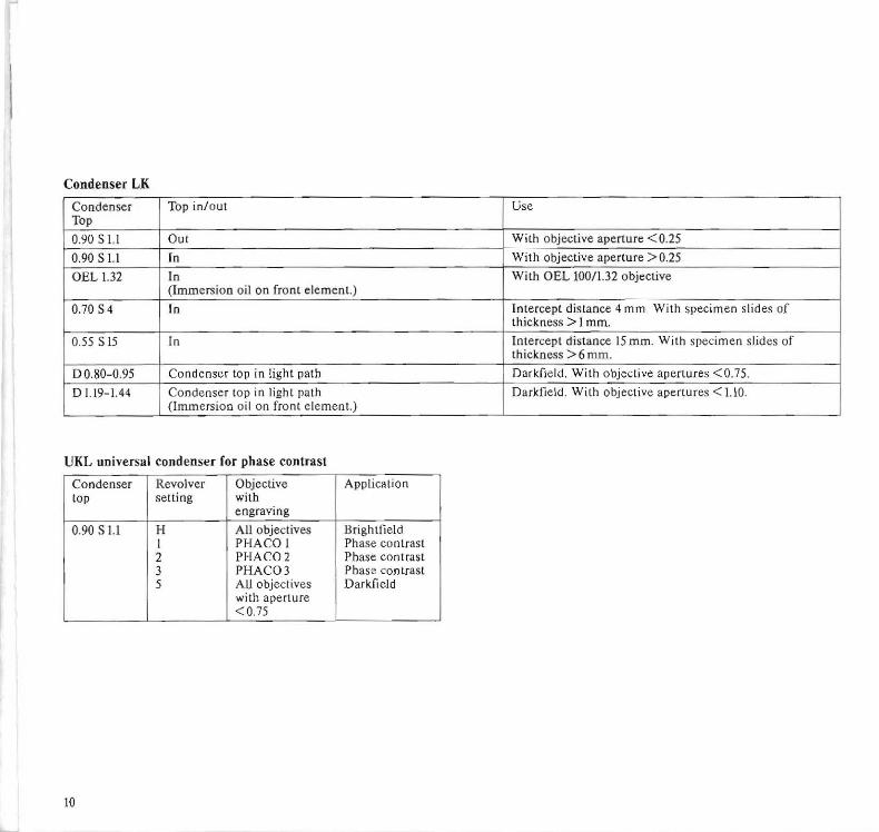
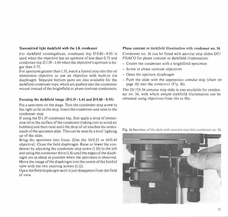
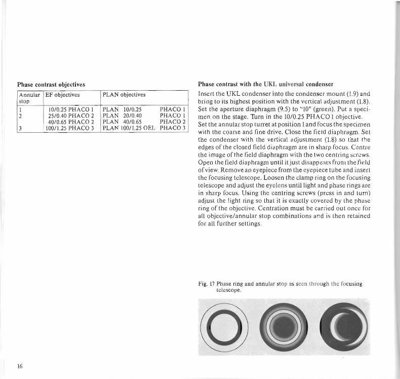