Embed Size (px)
Citation preview

i. ~. ~ 4NY NEW YORK UNIVERSITY
CtjScwoI of Engineerieg and ScienceW.RESEARCH DIVISIN
C:JMivenily Heighs, Bronx S3, N. Y.
DEVEL.OPMENT OF COATINGS ADiiLiR2T TIJ
MFETAiLS UND~ER VlbRATION CfONDITIONS
FINAL RL.PORT
May 20,01966
BURkAAU OF SHIPS,DkMPARM14T IV? THý. NAVY,CONTRACT No. N~bs 90357(N.Y.U. Engineering Froj'iit No.1130)
-m7~'''c ANDf0r0_ 7 ,~
psw~00 IV' Mlrqw V

DEVELOPM4ENT OF COATIRGS ADHUEENT TO METALS
UNDER VIBRATION CONDITIONS
FINAL. WEORT
May 20,t 1966
Max KronstelinProject Director
Bureau of Ships* Department of the Navy
Contract No.NObs 90357
(N.M.&.gineering Project No. 1.130)
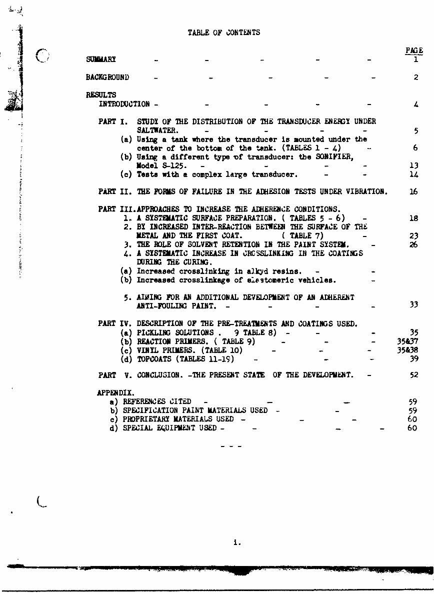
TABLE OF CONTENTS
BACKGROUND 2
RESULTSINTMOUCTION - 4
PART I. STUDY OF THE DISTRIBUTION OF THE TRANSDUCER ENERGX UNDERSALTWATER. - - - 5
(a) Using a tank where the transducer is mounted under thecenter of the bottom of the tank. (TABLES 1 - 4) - 6
(b) Using a different type of transducer: the SONIFIER,Model S-125. - - - 13
(c) Tests with a complex large transducer. - - 14
PART II. THE FORMS OF FAILURE IN THE ADHESION TESTS UNDER VIBRATION. 16
PART III.APPROACHES TO INCREASE THE ADHERENCE CONDITIONS.1i. A SYSTEiATIC SURFACE PREPARATION. ( TABLES 5 - 6) - 182. BY INCREASED INTER-REACTION BETWEM THE SURFACE OF THE
METAL AND THE FIRST COAT. ( TABLE 7) - 233. THE ROLE OF SOLVENT RETENTION IN THE PAINT SYSTEM. 2614. A SYSTEATIC INCREASE IN CRCSSLINKING IB THE COATINGS
DURING ME CURING.(a) Increased crosslInking in ai.kyd resins. -
(b) Increased crosslinkage of elestomeric vehicles. -
5. AIMING FOR AN ADDITIONAL DEVELOPMENT OF AN ADHERENTANTI-FOULING PAINT. - - - - 33
PART IV. DESCRIPTION OF THE PRE-TREATKENTS AND COATINGS USED.(a) PICKLING SOLUTIONS . 9 TABLE 8) - - - 35(b) REACTION PRIMERS. ( TABLE 9) - - - 35&37(c) VINYL PRIMERS. (TABLE 10) - - - 35&38(d) TOPCOATS (TABLES 11-19) - - - 39
PART V. CONCLUSION. -THE PRESENT STATE OF THE DEVELOPMk2T. - 52
APPENDIX.a) REFERENCES CITED -59
b) SPECIFICATION PAINT MATERIALS USED - 59c) PROPRIETARY MATERIALS USED - - - 60d) SPECIAL E&UIPMT USED - 60
J
i.

The work reported herein has been performed in Research Building No. 3
of the Research Division, School of Engineering and Science, New York University
under the direction of Dr. Max Kronstein, Senior Research Scientist. The members
of the research staff who have participated in the work are:
Mr. Raymond N. Handwerker Research Assistant
Mr. Lynne R. Harris Research Assistant
Miss Jane B. Lian Research Assistant
Mr. John M. Pascone Research Assistant
Miss Andrea X. Valentine Research Assistant
Mr. Arnold L. Van Aken Research Assistant
Dr. William H. hapfer Chemical Engineer
Mrs. Marion W. Kronstein Assistant Research Scientist.
ii.

SUMMAR!
The factors which influence the life of paint systems on steel under saltwater
and ultrasonic vibration have been studied. The sonic effects have been found to
differ in their effect which decreases the adherence of the coating system and their
effect which influences the coherence of the coatings with resultant cavitation. It
has been studiid in what form the transducer energy is distributed through saltwater:
some forms of transducers give up the energy in a form where it is being dispersed
throughout the whole saltwater area, with the greatest energy appearing close to the
entry area of the energy; but the energy continues to be effective in widening areas
at greater distances from the entry, and the energy is being reflected from the
metal walls of the saltwater tank and from the upper limit of the saltwater/air
interface back into the water. Another transducer gives off powerful energy but
only at a very short distance from the source and according to the narrowing diameter
of the energy source area. Large ship transducers can have both effectsrepresenting
a bundle of high-energy centers with the additional spreading of energy outside of
the area directly facing the transducer head. ( PART I)
The forms of failure which take pl-ýe are: loosening of parts of the film from
the steel substrate, local pinhole formation,and filament formntion. (PART II)
Increased adherence has been found to result from:(a) step-by-step surface
preparation,which includes surface inhibition and the driving off of entrapped air
in the valleys of the surface profile; (b) the use of primers, including the
specification wash-primer (F 117) and a red lead or zinc chromate vinyl primer so
applied that there is inter-reaction between one application and the next; tc)
avoiding solvent retention in each application before subsequent coatings are
applied; (d) bringing the paint system to a desirable state of cross-linking, or
polymer state, without going so far as to lose coherence in the paint film. (PART III)
A description of the pre-treatments used and experimental coating systems
L developed is given and discussed. (PART IV)
1.
BACIIGRUUND: THE PROBLU.
The project was concerned with the observation which had been made tn
Navy practice that under the influence of supersonic radiation and in the
area of radar radiation ship coatings develop areas of failure. At the
start of this project it had been assumed that these failures were caused
primarily by a loss of adhesion of the paint system under the effect of the
vibration which is caused by the path of supersonic energy through the sea-
water and affecting the painted surfaces. The earlier period of the work on
this project confirmed that under such vibration the conventional coatings
and coating applications begin to develop two kinds of failure rapidly: (a)
they begin to lose adhesion, especially from the edges; and (b) they
develop pitting and filament areas on many parts of the surface.
Primary aims of the project as outlined at its conception were an
elimination of the various sources of decreasing adhesion, and developing
coating systems which would resist the vibration energy in the saltwater due
to their uniformly cured condition. Both of these aims have been studied
to a great extent; and the time of resistance df applied coating systems under
comparative tests has increased from between 48 hours and 72 hours to several
hundred hours, with panels still in good state after th% extended time of
exposure. The step-by-step davelopment of the work is outlined in this report.
Nevertheless, on the other hand, it has been established that the factor
of vibration is not the only characteristic of sonar and supersonic radiation:
when the source of the energy is so constructed that the emitted energy is not
spread out in an extended water volume but is concentrated in powerful beams
of radiation, these beams cause besides vibration a strong impulse into the
coating system. Such beams actually penetrate into the paint system, resulting
in a piercing of the film and the formation of cavitations. This form of coating
2.

failure is independent of the vibration factor. With the highly adherent and
highly cross-linked system which offers the highest degree of adhesion, the
cohesion can be lower than that required to resist the direct frontal attack of
the high powered and concentrated beam.
This new problem of connecting the developed adhaeent and high1ly cross-
linked system with additional elements to increase its coherence, is not 71t fully
Volved. . The new system, whose development has come under way and which is
further to be completed, must maintain the good adhesion under supersonic
vitration obtained under the present contract and at the same time maintain a
maximum of cohesion against a frontal attack of strong and concentrated beams
of sonic and ultrasonic energy.
The present report covers the work from 27 April 1965 through 27 April 1966.
The preceding work to 27 April 1965 was reported in the Intermediate Progress
Report submitted May 29, 1965.
33.

RESULTS.INTRODUMTION
The work covered in this report is divided into the followirn sections:
" 0. , -P, +I A4 v 1,, ^r%,^P1• ,, , +.,-O ,tO',.#%,,o te,•,,,,..V 11ntlpy. • 1 .Wfl tA+.or
using different forms of transducers and different energy exposures.
II. The study of the different forms of loss of adhesion which have been
observed.
III. Studies on increasing the adhesion
1) by surface preparation
2) by increased inter-reaction between the surface of the metal end the
first coat.
3) by a systematic build-up of the coating system, avoiding retention of
solvent residues in the coating material which would interfere with
the uniform curing of the system and its inter-coating uniformity. The
'•d- is here a solid cure of the completed system.
4) by systematic increase of the degree of cross-linking in the coatings
during the curing. The optimum with respect to cross-linking requires
maintaining strong enough coherence to resist cavitation effects of
supersonic energy when facing the transducer source.
5) by aiming for an additional development of an anti-fouling paint which
will adhere to a well cured coating system and will also have enough
coherence to resist the cavitation effects of the supersonic radietion
when facing the transducer area.
IV. Review of the pre-treataents and coatings used
1) in the pre-treetment and priming of the metal
2) in the top coats, using specification paints and new experimental paints
3) in new forms of cross-lnking tbhrouhout the paint system.
V. Review of the present etatus of the development.
4.

PART I. STUDY OF THE DISTRIBVTION OF THE TRANSDUJkR ENJUG UNDER SA±,WATER.
The transducer energy dietribmtoin depends an the power used
aas o the O J 'in Wruch the energy is being released. The energy can either(a)
be released so that it will be dispersed over an extended area, as when a
transducer is mounted under the center of the bottom of a degreasing tank; or(b)
in another form a strong transducer might have a head of limited diameter and
the head itself might be so constructed that the emitted energy is not spread
out in a saltwater tank but ia concentrated in a small area in front of the
Shead. In form (a) the energy will enter the center area c,' the bottom of the
A tank and disperse throughout the tank under conditions which have been well
established during the work . Coated panels in such a tank will be exposed to
energy attack as well as to the vibration effect caused by this energy. In
form (b) the energy will cause a cavitation effect on an exposed surface, with
the diameter of the cavity smaller than the diqzeter of the head of the
transducer. Due to this pattern the center of the energy attack will be quite
close to the head and will decrease with the distance. It will nct cause any
special vibration effect to such an extent as to cause a general loss of
adhesion.
If a large transducer is used such as is used in certain haval Laboratories
the source might release bundles of energy, most of which is centered in a
number of beams, with a minor extent of energy radiating to the sides of these
beams. Such systems will cause a number of high powered effects which result
in a cavitation formtIcn for eanh of the beam centers. Some of the radiation
spreads out from tlin bundle of center beams over a wid~r area in the water.
Therefore, brth the factors of type (a) as well as the factors of type (b) wili 1e
of importance.
This is being discussed as ao~lows:
5.
mmmn,~ ~ ~ ~ ~ ~ ~ ~ ~~ ~" Mmumumua•wame IPie eew mm em

(a) Using a tank where the transducer is mounted under the center of the bottom
of the tank:
In the Intermediate Progress Report covering the work from 27 April 49W4
to 27 April 1965, the test panels were exposed in 5% saltwater solution in the
test tank of the SONOGEM 1GTH- 4 0 supersonic test device. No methods had been
available to determine at that time the manner of distribution of the energy
throughout the test tank. In the meantime such a method has been developed
by this group.
Data about the instrument are given in TABLE 1.
The spreading of the energy from the area of entry at the bottom of the
tank was first measured in its effect on aluminum foil and on coated steel
panels as the vertical spreading upwards from the z~re cf entry. ( See TABLE 2)
This wes done using the fact that an 0.5 mi thick alLminum foil irt progressingly
deteriorated by the entering energy to which the foil is exposed in 5% saltwater.
The size of the tank was as follows: Length 5 inchesWidth 5 inchesHeight of water
level 6 inches.
In TABLE 3 the horizontal spreading of the energy was measured by exposing in
horizontal position first one foil at a distance of 0.5 cm above the entry area,
a second one afterwards at a distance of 2.5 inches above the area of entry, and
finally a third one afterwards at a distan'e of 5 inches above the are of entry.
Since TABLE 2 had shown that the energy decreases with the height above
the area of entry, tlhe length of exposure was increased also with the increasing
distance. The results of the table show that with the increase of distance the
intensity of the waves ciecreases; but on the other hand the diameter of the area
of wave effect increases. This was shown in FIGURE 4 B of Letter Report No. 20:
when the foil was exposed horirontally 1 cm above the entry area, the diameter of
j the pinhole and cavitation area was 6.5 cm. or about half the diameter of the tank
* 6.5 cm 2.559 in.
6.
w .w w-i -- wq w q - mwm m • l a ••al I m •,w • Ia • m w , ,=, ,,, . m .

TABLE 1.
SOUi DATA ON THE S0NOGhLN lTH-40 SUPkERSOi410 TEST DEVICE
Manufacturered by Branson Instruments, Inc., Stamford, Zonnas MODLh ILT•-40
SDNOGEN ULTRASONIC GENERATOR WITH A TANK
Generator:Power output: average 40 watts with 80 watts peak on pulses.
Frequency: 25 kc
Input: 115 VAC/ 50-60 cycle and 120 watts.
Transducer: Frequency: 25 kc
Maximum Operating Temperature: 2000 Fahrenheit.
Heater capacity: 125 watts.
The transducer was mounted underneath the bottom of the tank.
7.

TABLE 2.
VERTICAL SPRPADLPj OF NEMYX
TESTED BW SUSPENDIN. AN ALUMINUM FOIL ( 0,5 skil THICK) VERTICALLI OVER
THE AREA OF ETRI 0.•' SUPLIR.MIC VIBRATION.
DISINTZRATIC6 OF THE FOIL MJE TO THE UTERING ENEJUI:
TIME HEIGHT OF DISINTB3RATIONI COMU4T
lot Period
1 miin. 2.5 ca.above the entry area. Rate of spreading in thelst Period: 2.5 @m./aun.
2nd Period
1 min. plus 1.5 &in. 2.5 ca plus 2.5 ca above Rate of spreading in 2ndentry area( with a pattern Period: 1.66 ca./min.,orof additional blisters indi- due to increasing distancecating the continuin, spread- 1/3 less than in 1st Period.ing of the disintegration.)
3rd Period
1 liin. plus 1.5 min. 2.5 cm.plus 2.5 cm. plus .OcmL Full disintegration withplus 0.5 min. additional 2 cm.of partial
disintegration.
7a8.
- -

TABLE 3.
SPREADING OF ENGY FROM THE ARMA OF UTHX
C ~TEST DEVICE USED: SONOGfl4 LGTH-40 SUPERSONIC TEST SET-UP.
ONE ALUMINUM FOIL ( 0.5 ail thick) WAS SUSPENDED IN HORIZONTAL POSITION COVEAINI
THE WHOLE TANK AREA ABOVE THE BOTTOM,, WITH ITS EMTRY AREA OF SUPLRSONI' ENEMYX.
A) DISTANCE FROM ENTRY AREA: 1 ca.DIAMETE& OF CAVI- DIAMETER OF SlI
TIME OF EXPOSURE EFFECT OF FOIL TIE8LARZA RGLE CAVITIES30 sec. CONSIDERABLE FOPHATIOP OF CAVITIES 6.5 oa(2.559 in) 0.5 to 1 cm.
AND AREA OF SMALL BL,16TERS.
60 see. SIZE AND DENSITY OF CAVITIES IN- 6.5 ca 0.5 to 1.5 cm.CREASED.
B) DISTANE FROM ENTRY AREA: 2.5 INCHES (6.3 ca)
30 sec. VERY MANY SMALL BLISTERS 9 ca.
60 sec. INCREASED BLISTERING.
3 min. IN CMTER AREA ONLY S9ALL PITS 9 ca. 0.5 to 1 cm.BUT LARGER CAVITIES ABOUT 3.5 caFROM CENTER.
N( ote that here the cavity formation required about 5 times the time of
exposure, while the distance has been increased only 2.5 times. The diameter
of the cavitation area had increased from 6.5 ca. to 9 ca., or by 38%.)
c) DISTANCE FROME TRX AREA: 5 INCHES ( 12.6 cm).
4 min. REQUIRED FOR SEVERE CAVITIES 12 cm 0.5 to 1 cm.
SMALL PITS in THE CENTER AREA: LAGER CAVITIES IN THE OUTER RANGE
OF THE 12 ca. DIAMETER AFFECTED AREA.
( Time required for formation of the larger cevities increased by 33%, when
the distance between TEST B AND C doubled. Nearly the whole tank area is
now affected by the energy.)
( See Photos to B) and C) in Letter Report 20, FIGS 3B , 30 and 4A).
9
9.

bottom. When the foil was exposed 2.5 inches 16.3 cm) above the bottom of the
tank the diameter of the affected area was 9 cm ( 3.543 in.) or about 70% of the
tank area. Uhen the foil was exposed 5 inches (12.6 cam ) above the bottom , the
diameter of the affected area was 12 cm ( 4.724 in.,' , or zore than 90% ot the tank
are&. gvsh h
This gives the pattern of the energy spreading in the test tank.
Upon extending the exposure tes4s to point coated SAE 1010 steel panels,
it is to be considered that the energy can only penetrate the paint film but not
the steel, and that therefore different effects will be visible on the painted
side which is facing the entry area and on the rmverse side of the panel, where
the energy is passing througi the panel into the inside of the paint. This is
the case especially when the panels are exposed close to the entry area of the
energy. The data observed on coated panels are shown in TABE 4. In the test
of this Table the distances are different from the tests with foils, in order to
take account of the panel thickness,and in order to allow that the panels are
in all distances fully Immersed in the saltwater.
The first test was made with the lower panel side 0.5 cm. from the entry
area of the vibration. In the second test, the same 2.5 inches ( 6.3 ca) distance
was used as with foils. In the third z•st, the panel was exposed 4.5 inches (12.6 cm)
from the bottom, in order to Immerse the reverse side also.
The test panels used in this specific study were either coated, after wire-
brushing, with one coat washprimer MIL-P-15328 (F.117) and twj coats red lead vinyl
primer VIL-P-15929 B (F. 119); or the two coats of red lead vinyl primer were
applied directly to the wire-brushed steel.
In TABLE 4 the intozesting observation is made that the energy waves which
are deflected by the zetal surface and are moving toward the walls of the tank are
-reflected from there back into the tank. Therefore they do affect the edges of
10.

TAbLE 4.
EXPOSING PAINT COATED 1010 STEEL PANgLS UNDER CORRESPONDIhO CONDITIONS TO THE
HORIZONTAL kXPOSURE TESTS OF TAbiJE 3.
PAINT COATING: 4 mils on each side of panel.
SIZE OF PANELS: COVER MOST OF TANK AREA, WITHOUT TOUCHING THE WALLS.
I. TEST GROUP EXPOSED WITH PANEL 0.5 cm ABOVE ENTRY AREA OF ULTRASONIC VIBRATION.
PANEL WITHGUT WASHPRI1ER: AFTER 2 HOURS EXPOSURE, EVIDENT !JOSS OF ADHESION DUE
TO VIBRATION. PITTING EFFECT ON SIDE FACING THE SOURCE AS WELL AS ON REVERSE SIDE.
PANEL WITH WASHPRIMER: SIDE FAZING THE SOUR•CE: PATTiRN OF LOCAL FAILURES OVeR
AN• AREA OF TWO S4JARE INCHES. ON REVERSE SIDE, AREA OF LOCAL FAIAJURE OVER ONE
SQUARE INCH AREA.
II. TEST GROUP EXPOSED WITH PANEL 2.5 INCHES ( 6.3 cm) ABOVE aTRY AREA.
THE PANELS WERE EXPOSED FOR 9 3/4 hours.
WITHOUT WASHPaJIER: THE SIDE FACING THE ENTRY ARLA SHOWS A FA1OURL AREA NOT AT
THE CENTER OF THE PANEL BUT bETWEEN THE CENTER AND AN kMr. AREA. ( THIS CORRESPONDS
TO THE PATTERN OF THE SPREADING OF ENERGY IN TABLE 3).
WITH WASHPRIMER, AND THEREFORE GREATaR ADHESION: Lr;SS FAILURE bUT IN THr. SALE
AREA. THE REVERSE SIDE SHOWED HARDLY ANY EFFECT.
III.TEST GROUP EXPOSED WITH PANEL 4.5 INCHES (12.6 cm) ABOVE &NTRY ARLA.
THE P&NELS WERE EXPOSED FOR 171 HOURS.
THE SIDE FACING THE ENTRY ARIA SHOWSWITHOUT WASH-PRIMeR AND WITH WASH-PRI1zR,
LITTLE EFFECT. THE EDGES AREU EXPOSED TO THE tEbrZ1GI PRESSING bETWEEN Tlit PAn.L
EMES AND THE TANK WALL, AND SOME L.OSS OF ADHREFNCE APPUARS IN THIS AREA.
THE SIDE FACING THE UPP.R LEVEL OF THL SALTWATrR AND EXPOSED TO THE, ENVY WAVES
REFLECTED FROM THE UPPER LEVEL OF THE WATER, SHOWS MORE FAILURE AREAS AND AREAS
CONSIDERABLY SPREAD OUT OVER THE PANELS.
11.

the coated panel and lift the paint film from there off the steel. This is the
case especially in the area 4.5 to 5 inches froL the entry area, where the tests
of TABLE 3 have shown that here the energy waves are affecting more than
90% of the tank area, even before the reflection effect.
When the energy waves reach the upper level of the saltwater in the tank, they
are reflected beck from there into the tank, so that in the case of the upper
position of the panels the painted side facing the entry area shows hardly any pitting
at a time when the side facing the reflection area of the water surface shows
considerable areas of failure. ( These tests are described in more detail in
Letter Report i•o. 23.)
12.

(b) Using a different type of transducer: the SONIFIER, MODEL S-125.
Thbe pass of the transducer energy depends not only on the pooer and frequency
of the generator, but also on the form in which the transducer gives off its energy.
For testing the influence of this characteristic, a highly concentrated energy
test-head was used in the form of the SONIFIER, MODEL S-125 (Heat Systems Company,
Melville-. Long Island, New York). This instrument is 15 inches long and has a
test-head one-half inch in diameter, so that the energy is given off a base of this
diameter. The instrument has the shape of an electric drill.
To study its effect on aluminum foils as well as on painted panels, a new
test set-up was built. It was a wooden, water-tight tank, 12 inches high, 12 inches
wide and 15 inches long filled with 5% saltwater. Seven and one-half inches from
one eand a movable frame was inserted for attaching the test panel. To allow free
movement of the energy waves, this frame had a rectangular window 3• inches by
7 inches in size, located in front of the instrument head. The transducer passes
first a water-free chamber and enters into the saltwater tank. The head is mounted
0.5 cm ( 0.1968 inch) from the test panel. The manufacturer claims that the
instrument gives off 1000 watts/sq. inch, or 500 watts from the one-half so. inch
head within a most effective distance of - to j inch.
When the aluminum foil is mounted 0.5 cm (0.1'968 in) from the head, a circular
hole is formed within 1 minute which is 1 cm. ( 0.3937 inch) in diameter, which is
less than the 0.5 inch (1.27 cm) diameter of the emitting head.
Uhen the foil is mounted at a distance of 0.85 cm. (0.2953 inch) from the head,
it takes three times the exposure time to puncture the foil, and the hole has a
diameter of 0.8 cm ( 0.288 inch).
This shows the very narrow pattern of energy distribution for this kind of
transducer. At a distance of 1.8 cm ( 0.7087 in.) no hole is formed in a 12 minute
exposure. The exposure of a painted surface showed a visible effect only at a very
short distance.
13.
- I" I -IIIII I I I !I III

(c) Tests with a complex large transducer.
Since this laboratory does not have Q large transducer such as is used inI
ships, the characteristics of these large transducers were not known by the group
until late in the contract period when some exposures were made with the cooperation
of the U.S. Naval Applied Science Laboratory in Brooklyn, N. Y. Because the tests
were made there, this group does not have all the instrumental details and all details
about the position of eazh panel in front of the energy source; but a critical
evaluation of the exposed panels establishes the following facts: these large
transducers are so constructed that they emit bundles of concentrated radiation,
each bundle similar to such a source as discussed under paragraph "b" but stronger
in energyand therefore the distance in which the bundle is effective. is greater.
When panels are exposed for approximately 24 hours in front of such a power source,
they are hit by a bundle of concentrated beams which produces for each beam one
cavitation area. Besides these individual bundles with their separate center
effects, the whole bundie gives up some additional energy which spreads out from
the center bundle to the sides and produces therefore effects over a wider area.
When the transducer is mounted in the dome of a ship, the main bundle of energy will
therefore hit the ship body straight ahead from the transducer source; 'but the side
radiation will reach the wider area at the sides of the dome.
""he tests at this time have shown that (1) the impact of the radiation in the
center of each radiation beam causes cavitation-like, piercing results cn the
coating surface, with the degree of penetration varying with t1e hardness of the
coating system. Hereby, a soft, poorly cured paint system of limited mechanical
resistance, will show less cavitation effect, but the system will show other forms
of failure. For instance, a special type antifouling paint over such a soft paint
system will show extensive cracking over a wide area. On the other hand, a highly
cross-linked system will show more c&vitation effect but it will be visible also
14.
S. . .. III -- -- - - -}. . 1 I I I I II . . I , •

that the radiation which is emitted from the center of the bundle is reflected
and spread out over a wider area.
It is presently our aim to develop a modification of the coatings where
the highly cross-linked experimental paints developed for the requirements of the
adhesion factor are further extended to their cohesive properties.
The tests have shown (2) that it is evident thatsimilar as under "b", the
center of each of the radiation beams is decreasing in diameter with the distance
of the impingement area of the panel from the energy source. Although the panels
which were exposed in the Naval Laboratory were mounted as nearly in similar
position &s possible, it is evident by comparison that the area of the radiation
effects in the formation of cavitation varies between the panels from two square
inches to three square inches; and at the same time the distance from one
cavitation center to the other varies, with the varying area from cavitation to
cavitation between 2/16 inch and 3/16 inch. More exposure tests and more
evaluations will be required to establish the rate of energy distribution. Where
the energy is spreading away from the center beam, different effects are to be
obtained which are less of the cavitation type and more of the type as outlined
imder position "a" of this PART I.
15.
-~ m • •

I!. THE FOMS OF FAILURE IN TH6 ADHESIONi TiSTS UNDWH VIbRATION.
Using conventional coatirng systa-s over pickled 1010 stee-- with an-
initial application of a wash-primer (Spec. Mi 3-P-15328 -Formui "17) followed
by one coat of a top coat, and suspending the air dried panel in 5% saltwater under
vibration, as outlined in PART I. pitting areas appear within 24 hours, especially
in the lower part of the panel which is close to the entry area of the energy.
These developing failures are not limited to the center area of the panel: smaller
pitting developments become visible further up in the panel, covering about the
whole lower half of the panel. At the same time the paint blisters off, not
only from the lower edge but all along the aides of the panel, independent of the
distance of the area from the entry of the vibration energy. By using the top-
coat in a different color than the primer, the progress of these developments is
clearly visible.
Using a different system, such as red lead vinyl primer MIL-P-15929 B,4
Formula 119, with a commercial neoprene paint ( N-39 Cold Bond ,Gates Engineering Co.)
similar developments are visible over the whole area of ths panel after 72 hours
exposure. ( Reference:Figures 1 and 2, Letter Report No. 5)
In other paint systems, the failure appeared in the form of filament
formations of increasing length, and peeling starting from the edge areas.
These developments differed from the results of other test methods, in
particular the saltfog exposure results. It was necessary, therefore, to
establish the reasons for these failures and to aim for an elimination of these
defects.
Any paint system consists of the top cxsts, as well as of the primers,and
the inter-face reaction area between the primers and the substrate, or the metal
surface which is to be coated. In the paint system there are usually several
Sdifferent paints, such as an anti-fouling paint, several coats of the main paint
16.

material used and the primer which is applied over a surface treatment or washprimer.
Each of these coats is expected to have different herdness, and a different form
or degree of curing; and between the various coating materials there is a different
degree of inter-reactivity.
All these factors affect the uniformity of the applied coating system and,
therefore, the degree of stability under the test. conditions. One important factor,
discussed in the Intermediate Progress Report of May 29, 1965; is the degree of
solvent retention in each of the applied coats before the application of the next
coat. TABLES 14-16 of that report gave data about varying film thickness caused
by solvent retention under varying temperature and curing conditions. Also the
effect of vacuum application was reportedand the effect of varying the solvent
types in diluting the paint. When a paint system is built on a series of still-
swollen layers, such as results from the retention of solvent, there is a continuing
change in the inter-layer conditions when the coating system continues to age.
Conditions arise, therefore, which are undesirable for the exposure in saltwater
under supersonic vibration.
The systematic curing of the individual coats, and the partial replacement
of toluene or zylene by 2 nitropropane improved the txposure results, as will be
shown further-on.
If one coating material has a limited bond to the preceding material, the
exposure tests will show a primary failure of that paint layer down to the next
paint material. Especially, the anti-fouling paints were found to have a limited
life over the main coating system.
The most important factor is the bond of the whole paint system to the metal
base. If a failure occurs here, a peeling of the whola system takes place, followed
by corrosion, usually starting from the edges. Therefore, the surface treatment, or
g the wash-primer coat, or the degree of bonding of the next primer to the wash-primer
coat is of primary importance to the life of the adhesion of the paint system. This is
further discissed in Part III.
17.

III. APPROACHES TO INCREASE THE ADHiRE;CE CONDITIONS.
The findings or. the factors which influence the adherence conditions under the
vibration test in 5% saltwater are being reviewed under the following aspects
1. A SYSTERATIC SURFACL PREPARATION.
It is of primary consideration in any systematic building up of a maximum
degree of adhesion for any paint system, that the system is anchored as eoll as
possible to the substrate. Since it is known and since it can be recorded with the
Brush Surface Analyser (Bznrsh Electronics Company, Cleveland, Ohio) that any metal
surface has, without systematic surface preparation, an irregular and not controlled
surface profile, the desired maximum adhesion requires a systematic modification of
that surface before paint application. This preparation consists of a removal of
rust and oxide layers, and in the preparation of a new and regular surface profile.
In the laboratory tests of this report, the surface was wire-brushed, and so a new
surface was obtained having greater reactivity than would have been available in a
partially or fully oxidized surface. On ships, such a surface preparation can
start with sand- or grit-blasting of the surface.
After wire-brushing, the newly obtained surface was subjected to a chemical
treatment with a rust-inhibiting pickle. It has been shown that such a rust
inhibiting pickle produces a chemical reaction coating on the freshly wire-brushed
steel. This has been shown by establishing the degree of chemical reaction coating
as the "stripping weight per square foot" surface, which amounts to 16.2 mg/sq.ft.
(More specific data is shown in the Intermediate Progress Report of the Project,
Tables 1 and 2.)
Due to the low viscosity of the pickling solution it might be expected that the
solution penetrated into the cavities of the profile , and that therefore the chemical
surface modification was extended into such areas of "depth" in the metal profile. It
might still be established in a future study how far the uniformity of such a penetration
18.
might be influenced further by the addition of agents for increasing the wetting
( C•. propertir,8 of the pickling solution.
Under the aspect of a chemically prepared surface, it is further to be assumed
that all subsequent building up of a highly adherent coating system depends on the
Sanchorage which is obtained between the newly prepared,chF-mically rust inhibited
surface and the subsequent coats of the coating s~stem.
Since the profile-depth areasor the cavities of the profile,have been chemically
modified without filling these areas, the continued systematic build-up of a fully
anchored paint system, still requires that the first primer coat should continue
to include the profile cavities in the coating process. One way is the application
of the wash-primer MIL-P-15328 B, which is of low viscosity and is reactive with the
substrate. Here again, future studies should include how far this uniform reaction
in the surface cavities can be increased by the use of wetting additives in the
4wash-primer type coating. But such a systematic preparation can be assumed to give
4 the substrate surface a quite well modified state.
Applying now a heavier primer coating, such primer should be based on reactive
pigments and should have maximum flow properties in covering all areas of the profile.
That reactive pigmentation has an influence on the inter-reaction in the build-up
was shown in the Intermediate Progress Report, Table 3, when it was shown that a
diluted, red lead-linseed oil primer caused an increase of the stripping weight over
that obtained by the rust inhibiting pickle. That the degree of wetting influences
the stripping weight increase was shown, also in the same Table 3, when a change in
the diluent from Xylene to 2 Nitropropane caused also an increase in the reaction
coating on the steel. It has been shown throughout the work that a red lead vinyl
primer MIL-P-15929 B over a wash-primer surface causes a further increase in the
reaction coatinr weight.
Reviewing at this time the knowledge which has been obtained, it appears that
19.
Am• •.• m •o num M~~M l l lul•i ~ IM llnllnumwmllnn lnmnmnnlvmum'n .

in future work, studies should be made on how far the flow of the vinyl primers
( red lead or zinc chromate vinyl Drimers) might be influenced further by the use
of systematic additives, and how far this would result in e still more uniformly
developed inter-linkage and adhesion stability.
TABLE 5 in this report gives the factors which have been reviewed up to this
time. New factors, which have been studied in the report period,are tabulated in
TABLE 6. They refer to the following:
a) the temperature of the pickling solution. The fact that TABLE 6 shows a
higher weight of the reaction coating with the increase in temperature of the pickling
solution is assumed to have two reasons: one is the increase of the reaction in a hot
solution; the other is the degree of air removal from the cavities of the metal
profile with increasing penetration of the pickling solution into the cavities. This
results in a more complete chemical surface modification. In ship practice, the
pickling ;ight be considered by a hot-chemical,surface-modifying spray application.
b) the selection of the complex-forming metal component in the pickling
solution.TABLL 6 shows that the otherwise same solutions increase in the resulting
weight of the reaction coating with the variatinn with a sodium dichromate pickle,
and a sodium molybdate pickle, eventually under the addition of a ceric sulfate
agent. Other factors which have been considered are the introduction of metallic
zinc into the primer.
It has also been observed that a wire-brushed surface might be flame-oxidized
before the application of a hot pickle, whoreafter a further increase in stripping
weight has been observed. This had been reported in more detail in Letter Report No.19.
For the purpose of uniformity, in most paint applications in this report the
standard rust inhibiting pickle was used hot, which gave satisfactory results with the
various systems.
20.

TABLE 5.
FACTORS OF A PSTPIq SU*AhL P(AMAUTiOb
1. ESTABLISHING A SURFACE PREPARED FOR MAXIMUM PAINT ADHEWRF CEs
a) REMOVAL OF ADIERENT RUST AND OF OXIDATION LAXtS BY
EITHER WIR-BRUSHING OR
BY SAND (GRIT) BLASTING.
SIMULTANEOUSLX OBTAINING A MORE UNIFOYS PROFILE OR NETWORK bET+WLE CAVITIES
AND SURFACE LAYtRS.
b) MODIFYING THE EXPOSED SURFACE IN ALL AREAS BY CHEMICAL TREATMENT
BY THE~ USE OF A RUST INHIBITING PICKLE ( LOW VISCOSITY.. PL~iJrRATiNG AND
REACTIVE)
2. APPLICATION OF WELL ANCHORED PRIMERS.
a) USING A REACTIVE LOW VISCOSITY WASH-PRIMER MIL-P-15328 B, WHICH IS RLACTIV, AiIii
STEEL AND IS INT&L't-R6ACTU'G WITH ThE LOW STRIPPI6G vtLk.GHT RLAOTIuN COATING
WHICH RESULTS FROM THE RUST INHIbITING PICKLE.
b) OR APPLICATION OF REACTIVE OIL PRIMkiR, SUCH AS RPod LrAD-LINSE&D OIL
PRIMER IN A FOiM WHICH IS NOT TOO VISCOUS TO ?EM.TRATi IATU THb PICKLtD
"CAVITIES" OF THE PROFILE.
A SECOND PRIMER COAT CAN BE OF HIGHER VISCOSITY, IF USED.
3. APPLICATION OF VARIOUS COATING SXSTEMS OVER THE WASH-PRIMlY ( 2-a):
a) APPLICATION OF RED L.EAD VINYL PRIMER ( MIL-P-15929 B, Formula 119) OR
ZINC CHROMATE VINYL PRIMER ( MIL-P-15930 B, Formula 120), AIMING FOR GOOD
AIDERENCE TO THE PR&CEDING WASH-PRIMeR.
b) SUBSEQUENT APPLICATION OF VARIOUS SPECIFICATION PAINTS, OR NEW kiXP.RIUM.NTAL
PAINTS AS DISCUSSED LATER IN THIS REPORT.
21.
TABLE 6.
NEWLX STUDIED FACTOIRS IN Rkat%.TiNG THE MI±.TAL 6UKiVACE
A)USED: RUST INHIbITING PI,'KLE (from TALkL 1, IBTEP.4EDIATE REPORT), AT VAR!UCG TiEPERATURE.
THE PICKLE: A SOLUTION WAS MADE OF 5.86 g. Na Zr2 O7
i. AND 5.59 g. PHOSPHORIC ACIP 85%
IA 400 ml. WATER.
A4NOTHER SOLUTIOA WAS MADE OF
II. 25 g. SULFURIC ACID
AND 225 g. WATER.
TO THIS SOLUTION II
10 g. OF SOLUTION I WERE ADDr;D.
TREATMENT WEIGHT:BEFORE AFTER WEIGHT LOSS AREA STRIPPING WEIGHTSTRIPPING (g) mg. sq.in. mg/sq.ft.
SAE 1010 STEELIMMERSED IN STANDARD 109.0888 109.0865 2.3 34.0 10.0PIh'K•E AT R.I.
SAME PICKLE, INCREASINGTHE REACTIVITY WITH 110.4764 110.4'/21 4.3 34.0 1F.20.5% SELENOUS ACID ATR. T.
USING THE STANDARD 110.1126 110.1085 4.1 13.5 43.6PICKLE Nr.AR BOILINGTEMPERATURE.
B)VARYING THE COMPLkX FORING COMPONENT IN THt PICKLING SOLUTION (NeAR bOILING POINT).WITH RJZULAR PICKLE 4.1 13.5 43.6
( SODIUM DICHROMATE)
REPLACING THE SODIUM DI- 9.0 20.62 62.8CHRQMATE BY SODIUM MOLYB-DATE ( SAMz AMOUNT)
SAME, BUT ADDING 5 ml. OF A 10.9 20.62 69.3SOLUTION OF 1 g.CERIC SULFATEIN 100 m1.SULFURIC ACID(1O%).
RPEPLACING THk SODIUM DICHR(MATE bY 9.5 20.62 66.45 g. MOLYBDENYL ACETYL ACZ.TONATE.
22.

APPROACHES TO INR•_ESE THE .A4 .PCE C OND!TIONS- (C.,tinue,,
01 VV TM.IflVAV T £L T U &MI~r% VN!?A IMY f*1 nr'M.n" i.MI- ^11- % 'ILAINOTMA,)&a In~Tra-fl.A.ftLON VL10ralt 4Inkl SURFlA~rA Or In1d MLIAI AD~D TH6 !±ZlbI QiAT.
This Section 2 continues basically the principles outlined in the preceding
Section 1; but here the primers are applied to the mechanically prepared and chemically
pickled surfaces. In TABLE 5 it has already been pointed out that either a
reactive pigment/oil primer can be used in a diluted form so that it will penetrate
into the cavities of the profile and will inter-react there; or, the specification
wash-primer MIL-P-15328, Formula 117, can be used, which is of low viscosity,
penetrating quality and surface reacting. In these cases the system can continue
with the application either of a red lead vinyl primer (NIL-P-15929 B, Formula 119)
or a zinc chromate vinyl primer (MIL-P-15930 B, Formula 120). In all these cases
the primer can inter-react chemically with the chemically modified metal surface
of the preceding Section 1.
Some data which substantiate this are shown in TABUz 7.
In the second part of TABLE 7 it is interesting to note that the stripping
weight did not notably increase when zinc dust was added to the red lead vinyl
primer. This is assumed to be caused not by a lack of reactjvity of the zinc
component, but rather by a lack of penetration of the highly pigmented paint into the
cavities of the surface profile. This results in a lesser degree of chemical
inter-reaction in these areas. That, in the same Table 7, the addition of aluminum
decreased the resulting reaction coating, in spite of the use of low viscosity
dispersing agent for the aluminum, is due to the very low degree cf reactivity of
the aluminum in these systems.
Reviewing at thir state again the adhesion under vibration of these primer
systems, it is a repeated observation that an application of the red lead vinyl primer
over wire-brushed steel without and with pickling has, under 5% saltwater exposure
in the first of the described test ";ystems for the effect of supersonic vibration
"( "a", on page 4 ), a very poor life before the vinyl primer film loses its adherence
23.

TA-bLE?
"A-.L.�JI , IZevAL In cat-fE.AAI j-.llA1 Or A a.AnJJ.lAV rZS1.LM4% W111 ALUi ALAO-AAI&A.1Lram
SURFACE UNDERNLATH
STEP I. HOT PICKL14G OF WIRE-BRJSHED STEEL: STRTPPING WEIGHT OF THE REACTION COATING.
WEIGHT BEFORE AFTER WEIGHT LOSS AREA STRIPPING WiIGHTSTRIPPING(grams) ug. Sq. in. mg/sq.ft.
110.1126 flO.1085 4.1 13.5 43.6
STEP II. AFTER APPLICATION OF WASH-PRIMER (Spec. MIL-P-15328, F.117)OVER HOT PICKLEDSTEEL
73.0533 73.0464 7.0 16.5 61.4
STEP III. AFTER APPLICATION OF THE RED LEAD VINYL PRIMER (MIL-P-15929 B, F.119) OVER THEWASHPRIMER
72.9275 72.9192 8.3 16.5 72.15
INFLUENCE OF METAL ADDITIONS TO THE RED LEAD VINYL PRIMER ( F. U19)
a) ADDING TO 500 9. VINYL RED LEAD PRIMrR
112.5 g. Z•NC DUST #22 (New Jersey Zinc Co.):
72.9166 72.9082 8.4 16.5 73.1
b) ADDING TO 200 g. RED LEAD VINYL PRIMER25 g. ALUMINUM 5 XD (Reynolds Metals Co.,Louisville, Ky.)
(DISPERSED IN METHIL ISO-BUTYL KETONE)
72.9870 72.9795 7.5 16.5 64.0
24.

to the steel owan.d peels off froM the edges. The same primer over hot pickle and wesh-primer maintains this adhesion for a much io-iger time and any failure -hich begIns to
develop afterwards is in the form of local pitting or filament formation rather than
A a straight loss of the film adherence.
.. The pitting formation proceeds then somewhat faster when the zinc chromate
vinyl primer (MIL-P-15930 B, Formula 120) has been applied than in the case of the
red lead vinyl primer of MIL-P-15929 B, Formula 119. ( Reference:Letter Report No. 16,
Fig. 1)
That is why often in haval practice both primers are being applied successfully
instead of two coats of one type.
25.
mom "-• . . . " .- • . .. . ,• -••:•,.. • Bl " l L,. ..

APPROACH8LS TO IhORLASk, THL ADHrRINCi O.Xt'INDiTIONS (Continued)
3 THEi RFI.. OF SOLVENT RiTENTION IN Thr PA1I1T SYSTL.
It has been pointed out in the Intermediate Report that the factor of
solvent retention in multi-coat paint systems is a factor to be considered in
the stability of paint systems unuer saltwater and under vibration conaitlons.
Any paint coating represents a formation which has the tendency to retain sweller
material, or solvent residues, in the paint layer. Upon aging, or under
temperature variations the retained solvent is gradually being d-iven out. This
results in a decrease in the volume of the paint layer and produces, in the case
of a multi-layer coeting system, pressure on the upperlying coat. Exposure in
saltwater adds the additional factor that the saltwater tends to penetrate in the
coating system; and, depending cn the degree of curing or on the decrease in
solvent retention, increases the resistance of the coating ageinst the saltwater
penetration. The factor of exposure th6n to supersonic vibration under saltwater
further accelerates the paint failure and the loss of adherence between the
various coats and between the whole system and the substrate.
In the first year's work of the contract, the considerable amount of solvent
retention in a vinyl system was determined. It was shown that the total coating
thickness varied for an application with an air-drying of all coats vs. an
0application of 15 minutes exposure to 90 Centigrade for each coat. It was shown
that the panel with the highest amount of retained solvent and a coating thickness
of 30 mils had large pinholes and blisters after 40 hours exposure in 5% sa- water
with supersonic vibrationwhen a corresponding panel with increased curing had
a total film thickness of 26 mils and was in good condition after the same
exposure test. ( Ref:Intermediate Report, Tables 14 and 15).
During the further work, we proceeded to twhs use of coatings containing
highly cross-linked vehicles or containing elastomeric polymers in the vehicles.
26.

w J r
AiJ
also in the gel properties. Also, every gel is characterized by its swelling with
solvents. Hereby, the solvent penetrates into the gel network and will find a
d greater resistance to complete evaporation from this state. Therefore the importance
of this point has increased further in the new coating developments. It has been
pointed out ( Interim Progress Report, Tables 17 - 19 ) that a solvent such as
2 nitropropane shows less retention of solvent in the coatings than, for instance,
xylene or toluene. Therefore, some of this material has been included in the
experimental coetings , which are discussed in PART IV of this report, and the
results continued to be satisfactory. It is espec.al.ly important to consider the
influence of solvent retention when coatings of different chemical character are
being applied on top of one another. When the final coat, for instance an anti-
fouling paint coathas less solvent retention than the elastomeric coatings under-
neath, the vibration test shows , in exposure to 5% saltwater and vibration, a
peeling of the anti-fouling paint from the underlying system. Using anti-fouling
paint awl the main paint system in different colors, the underlying system appears
quite quickly upon exposure to supersonic vibration when the anti-fouling paint is
not fully bound together in a joint system with the main paint sy- •,em.
There is still another factor which has not been fully and clearly established.
It is known in the field of electrical insulation applications that in applying a
coating of lower content of sweller, or plasticizer, over a coating with a higher
content of sweller, a migration takes place of the sweller ( plasticizer) from the
material with the higher content of swelling matter to the material with the lower
content of swelling matter. A similar phenomenon can be expected to take place
between the ship coatings also. If the last coat under these conditions should
c have turned very hard, it might develop the formation of surface cracking. This
27.

form.of paint failure has been observed in recent studies using a polyisobutylene II
complete paint systems, including new anti-fouling paints, this factor must be taken
into consideration.
28.

APPROACHES TO INCREASE THE ADHERENCL CONDITIONS (Continued),
i "- h.. A SISTEMATIt. IN,]RIASE IN R .O .ITNKIT r._ T Wk. I• T .aPTL•. , M.r T f.tj.
In the usual practice the various coating materials have been identified
according to their film-forming vehicles and their pigmentation. The general
specifications give no indication about the degree of polymer properties in such
materiis. They do not refer to the degree of the progressing polymerization
which is taking place during the curing of the applied coating. It must be
understood that the vehicle of such paints might contain some materials which
are polymerised to a certain degree and that thosa materials might, upon drying
or curing, progress in their polymer state; for instance, alkyds in vehicles or
phenolic resins in -rehicles belong to this group. Other vehicles might cortain
elastomeric components, such as neoprene or polyisobutylens, which contain
polymer matter to a certain per centage. These elastomeric componen-s usually
progress only slightly in their polymer state upon air drying of such coatings.
All these progressing steps in the polymerization of coatings can be
influenced chemically !.n an effort to produce more highly crosslinked or denser
polymer films,or filmb of greater resistance to solvent swelling or to saltwater
penetration.
(a) Increased crosslinking in alkyd resins:
It is to be understood that every polymer material which is being
introduced in the coating system consists for itself of highly polymer, insolt,'blR-
but-swelling matter together with low polymer or still-not-polymer matter, which
acts as a sweller in the polymer material which is being used in the preparation
of the coating material. Therefore, these polymers are mixed-phase or heterophase
substances. A chemical increase of the high polymer phase in the paint increases
the characteristic polymer properties of the coating.
29.
'~~~~ "5...3 pl

The project director has studied this in the case of cil modified alkyd
r Suc .... a oo ,, 4in Navy praint~s in P n~nr whir'h hpq been presented during
the project. (Reference:American Chiemical Society, Division of Orgenic Coatings
and Plastics Chemistry, Preprint book, "Papets Presented at the Detroit Meeting",
Vol. 25, No. 1, pages 105-115, April 1965). While that particular study had been
a part of the work under Grant GP-929 of the National Science Foundation, some of
the findings are important for the work approach of the present study. It has been
shown In sald paper that a long oil soya modified alkyd resin, according to
Specification TT-R-266a, such as the cormercial AROPiAZ 1266 M 70, has in its
initial form ( such as is being used in the pr•'paration of a specification paint)
only a small ratio of three dimensional polymer matter. That is why the electron
diffraction spectrum of that alkyd has the usual halo pattern. When, however,
suc-h an alkyd is further cured in a coating, such as by heating 16 grams alkyd
solution (70%) with 0.65 gram t butyl perbenzoate, a new polymer matter is being
formed. Since any oil modified alkyd according to said specification represents a
combination of materials, its resulting polymer has similar properties as poly-
chrystalline units have. They show in their electron diffraction spectre under
different atomic orientation with different angles of the electron beam also
different spectra. (See FIGUR6S 6, 8 -10 of above pre-print paper)
Going one step further, it is to be considered that in a specification
alkyd paint the vehicle might contain 6ther components also; and these can contribute
to the reactions which take place in the curing of the paint. To establish this
fact, the same paper used as an example a mixture of the same alkyd with a basic
zinc octoate, that is, a material of the group of the usual octoate driers. When
this mixture was heated with the t butyl perbenzoate and the new polymerization
product was isolated, a completely different electron diffraction spectrum was
obtained. (See Figure 15 of above pre-print paper).
30,

%i noM lw vrAus won fHovu AivitaA 4"f^~ a ,.~Iiftan m*%4^Mf 4ý -as"I~ uVA-J6
IC benzene and antother phase which is not soluble in boiling benzene. The phase
solids were in this form isolated and studied under the electron microscope. (See
FIGURES 16 and 19 of said pre-print paper). Fully different patterns were obtained
"for each phase and different also from the initial alkyd itself. In this form it has
been established that each alkyd vehicle can be changed chemically by progressing
polymerization or sustained cross-linking. The resulting paint is then not only
a product of surface drying but is chemically modified throughout its mass. That
is why new and desirable properties can be given to such aikyds by systematic
crosslinking, and it is of great importance in what form such paint vehicles are
when they are applied to the ship.
(b) The increased crosslinkage of elastomeric vehicles.
It has been studied how far this basic approach can be used on the chemical
cross-linking of elastomers, such as neoprene,or polyisobutyiene, or others. This
research group has shown earlier that all elastomers represent mixed phasesor
heterophase polymer materialsin which the ratio of the three dimensional phase(1)
to the low polymer and still-soluble phase produces the properties of each elastomer.
In most elastomers the percentage of the insoluble phase is considerably lower than,
for instance, in thermosetting resinous polymers; and since these elastomers have a
considerable capacity of swelling in solvents, the concentretion of an elastomer
in a so-called solution is usually low. Within this elastomer, therefore, the
concentration of the high rolymer phase in the solution is very low. Therefore,
the paints based on such solutions harden slowly and not to a fully satisfactory
degree. It is necessary, therefore, to develop methods for their additional
cross-linkage in the produced paints, in the state preceding their application as
well as after the application of these paints.
In the Intermediate Progress Report of this project (May 29, 1965) this
31.
iI
Crv35141P__wfa a4,%A4,I 4r% +ha~ oncap mf~ riannrnAna- 1minru t.pt.r R1kv1 t.1tnA~taA..%,SS -" - ' - - - - - r --. - - -r - _ -__ _
or their epoxide derivatives as cross-linking agents. (The preparation of such an
epoxide was described by Kronstein, Carroad and Byrd in an earlier paper which has(2)
been published in the OFFIJIAL DIGEST , Vol. 37, No. 482, page 284, March 1965.) The
Intermediate Report gave photos of the cross-linking effect in neoprene in
FIGURES 2 to 7 of said report. This cross-linking effect is not limited to neoprene,
however, or any other specific elastomer. This group has not been able to find any
kind of elastomer as yet, which did not follow similar patterns of increased
cross-linkage. Even natural rubber follows the same pattern when a rubber "solution"
is reacted with a tetra octyl titanate ( Ref: FIGURkS 1, 2 and 3 in JOURNAL OF PAINT(1)
TECHNOLOGY, Vol. 38, No. 492, pages 38-39, January 1966) , and the polymer phase
is being precipitated. Upon re-swelling, such pclymers form films. Similar
cross-linking effects have been established on a number of synthetic rubbers such
as styrene-butadiene rubber, butadiene-acrylonitrile rubber, Thiokol, butyl rubber,
silicone rubber, and other elast')mers such as vinyl chloride/vinylidene chloride,
and polyvinyl acetate.(1)-. These basic findings have been used in the experimental paints which are
being listed later-on. It has been established in this present work that such
polymers can continue to harden by extended cross-linkage to a state where they
obtain a glass-like hardness. it is presently wider study how this hardness can
be controlled to reach and maintain the required optimum. Two app-oaches are under
study: the use of a limited amount of plasticizer such as tri.resyl phosphate or
the incorporation of a limited amount of a less hardening type of a synthetic
rubber, such as is known in the industry as liquid rubber forms. Under study here
is a very low molecular weight copolymer of butadiene and acrylonitrile with a
medium-high acrylonitrile content. This is still under development.
32.

5. AIMING FOR AN ADDITIONAL DEVELOPIIMT OF AN ADHERENT ANTI-FOULING PAINT.
It is the present practice to apply In ship use one or two coats of
anti-fouling paint to any paint system, without consideration how far these4 final coats are chemically and physically inter-linking with the main paint
system. These anti-fouling paints have been developed primarily as a
suspension of a large percentage of pigments with toxic properties. The vehicle
has here the primary purpose of forming enough filn characteristics to hold the
high concentration of toxic pigmentation to the surface of the coating system.
The vehicles are generally so selected as to have limited coherence and Limited
underwater life, so that on deterioration the toxic pigment might be released.
For example, the anti-fouling paint Formula 121/63 is using 1440 lbs. cuprous
oxide with 55 lbs. vinyl chloride-acetate copolymer, or using, 100 lbs. pigmeont
with 3.8 lbs. film former. To extend the film former, 215 lbs. pine rosin is
added, which is included in the paint film without having any film forming
properties for itself. Since this mixture is too brittle, 50 lbs. tricresylphosphete
is added as a softener. The resulting paint film is in its composition contrary
to all general principles of an underwater top coat, but it releases during its
deterioration large amounts of cuprous oxide.
When exposed directly to the power of strong transducer energy, this
energy pierces the coating quickly and the underlying paint is being exposed.
Similar is the basic composition and general behavior of anti-fouling paint
Formula 134, where polyisobutylene is used as film former and where the ratio of
film former to cuprous oxide pigment is somewhe-. higher than in Formula 121/63.
Here 45 lbs. polyisobutylene polymer is used with 700 lbs. cuprous oxide, hs rdening
this mixture with 32 lbs. pine rosin. This is a ratio of 6.43 lbs. film
former to 100 lbs. toxic pigment. i•ut here still the film is so herd that underC "I�*L--P-22299 (SHIPS)
33'

direct exposure to the transducer energy, the radiation energy pierces the anti-
fouling paint layer readily down to the mnderlying paint system.
In aiming for a new Rnd systemati- paint system, which produces the maximum
resistance under adhesion in the range of supersonic vibration two new approaches
have been traced, although it was not possible to pursue the development of new )
anti.-fouling paints within the scope of the present work. These refer to (a)
producing a high polymer vehicle binder for toxic pigmentation and (b) to
incorporate into this polymer vehicle metalorganic components which have toxic
properties. Such vehicles can then be pigmented with toxic pigmentation besides
the toxic properties of the vehicle.
Especially, tin organics have been explored. The difficulty was at this time
to find a method to determine the rate of toxic release under saltwater and under
supersonic vibration exposure. The vehicles which have been tested at the present
time and using tin octoate as a part of the metalorganic part of the polymer
complexes had such a long saltwater life under vibration conditions that time did
te not allow coming to definite results about its toxic release. This problem of
anti-fouling paints will have to be pursued for itself.
344.

IV. DESORIPTION OF THE PR,-TRUATNTS AND •OATINGS USL.D.
In the following tables the composition is listed of the materials which
were used in this work:(a) TABLE 8 lists some of the pickling solutions, either according to Navy
practiceor modificationsand new solutions; but in all cases the purpose is the
same, to produce a reactive solution of low viscosity which is capable of
penetrating all parts of the surface, including the profile cavities fully and to
product there a new reaction layer, which seals the earlier deoxidized surface
against new oxidation until the next treatment is being applied.
(b) TABLE 9 lists reaction primers, including the specification wash-primer,
whose purpose is to continue the reaction coating build-up on all parts of the
surface, again, including its cavities. The Table shows three different groups
of wwash-primers". But again it is to be pointed out that with respect to the
basic approach of reactive primer-coat formations over 911 areas of a profile
many other formulations are possible.
(c) TABLE 10 gives vinyl primers, which can be applied over these pre-treated
and wash-primed surfaces. It is possible to apply this type of primer in two
coats, wher -y the first coat might be used in a more diluted form to facilitate
the anchorage in the profiles of the surface. It is possible also to use one
coat of a red lead vinyl primer followel by one coat of zinc chromate vinyl
primer, or in a reversed order. TAbIk; 10 refers also to the fact that such a
primer can be combined with a metal powder, either zinc dust or aluminum. In
the case of the zinc dust the corrosion resistance might be satisfactory, but
the penetration into the cavity areas of the surface is more difficult with such
a combined pigmentation and therefore in the tests of the Table did not show
increased stripping weight over the sema primer without the addition of zinc dust.
35.

~m.
FORMULATIONS USED IN THE CUFQE* hi90ii T PFEUJD (I.)
TABLE 8
INHIBITING SURFACE :'ICKL7NG SOLUTIONS
THE STANDARD PICKLING SOLUTION:
a) 5.9 g SODIUM DICHROMATE
5.6 g PHOSPHORIC ACID OR'.HO 85%
IN 400 g WATER
b) 25 g SULFURIC ACID CONC
225 g WATER
c) 1 0 g SOLUTION a ADDED TO 250 g SOLUTION b
USED: SOLUTION AT R.T. AND
SOLUTION NEAR B1 OILING POINT: DIFFERENT EFFECTS SHOWN IN TABLE 6
USED IN MOST OF THE SUBSEQUENT APPLICATIONS: NEAR THE BOILING POINT.
MODIFICATIONS USED:
1) ADrING 0.5 % SELENOUS ACID (AT R.T.)
EFFECT IN INCREASING REACTION COATING WEIGHT • AT R.T.)SEE TABLE 6-A
2) USING SODIUM MOLYBDATE-INSTEAD OF SODIUM DICHROMATE
EFFECT IN INCI•EASING REACTION COATING W]EIGHT ( NEAR BOILING POINT)
SEE IN TABLE 6 - B
3) PREPARING PART a IN THlE STANDARD SOLUTION FROM: 5 g MOLYqDENYL ACETYLACETONATE
5 g PHOSPHORIC ACID400 g WATER
EFFECT ON COATING WEIGHT (NEAR BOILING P ,INT) SEE TABLE 6 -B
36.

FORMULATIONS USED IN THE CURRENT REPORT PERIOD (II)
C TABLE 9
a) REACTION PRIMERS USED IN THIS WORK PERIOD
THE SPECIFICATION WASH*RIMER MIL-P -15328 B (FORMULA 117)
SINFLUEN CE ON THE PRECEDING PICKLING LAYER IN TABLE 5
INCREASING EFFECT ON THE REACTION COATING IN TABLE 7 STEP II
THIS MATERIAL WAS USED IN MOST TESTS AS WASHPRIMER
b) A COMMERCIAL EPOXY TYPE .ASHPRIMER BASED ON SHELL'S EPONOL 55 RESIN
THE FORMULATION WAS GIVEN IN THE INTERMEDIATE REPORT ,TABLE 27 - II
Ac) DIFFERDNT REACTION PRIMER USED OVER THE PICKLE:
( CODE V-2-85) 15 g MOLYBDEIYL ACETYL ACETONATE
1 IN 500 mls ACETONE
75 g ALKYDRESIN (AROPLAZ 1266 - M 70)
THE PANELS WERE DIPPED FOUR TIMES AT 30 SEC.INTERVAL
OF WIPING THIS COATING OFF WITH TOLUOL A BROWNISH -BLUE REACTION LAYER WAS
EXPOSED.
WHEN A VINYL PRIMER AND A TOPCOAT WAS APPLIED OVER THIS MX, PRIMERTHE RESULTING
TOTAL FILMTHICKNESS WAS THE SAME AS WHEN THE STANDARD WASHPRIMER a) HAD BE2E USED.
OTHER EXPERIMENTAL FORMULATIONS HAVE BEEN USED ALSO-
37'.

FORMULATIONS USRD TN THE ClU :',NT RrPnAR DPDTnIT)ITTT N
TABLE 10
VARIOUS FORMS OF VINYL PRIMERS Ia) THE RED LFAD VINYL PRIMER MIL -P-15929 B FORMULA 119
b) THE ZINC CHROMATE VINYL PRIMER ?MIL-P-15930 B FORMULA 120
c) APPLICATIONS OF BOTH THESE PRIMERS
d) EXPERIMENTAL ADDITIONS OF ZINC POWDER TO RED LEAD VINYL PRIMER
112.5 g ZINC IXJST # 22 TO
500 g VINYL RED LEAD PRIMER a)
INFLUENCE ON STRIPPING WEIGHT SEE TABLE 7
e) EXPERIMENTAL ADDITION OF ALU.K.NTJM POWDER TO RED LEAD VINYL PRIMER
200 g RED LEAD VINYL PRIMER
20 g ALUMINUM 5 XD (PREDISPFRSED IN METHYL ISOBUTYL KETONE)
INFLUENCE ON STRIPPING WEIGHT SEE TABLE 7
TFSTED AGAINST # a(OVER PICKLE AND WASHPRIMER)( THE PICKLE USED WAS THE MODIFICATION 1) OF TABLE 8)
AFTER TEST IN WITH RED LEAD VINYL PRIMER WITH RED LEAD /ALUMINUM # e5% SALTWATER UNDER
SUPERSONIC VIBRATION
AFT•R 90 HOURS VERY GOOD CONDITION GOOD CONDITION, RUT ONESMALL PINHOLE
AFTER 106H1OURS GOOD CONDITION WITH FIVE TO SIX PINHOLES ONSEVFERAL SCATTERED FINE EACH SIDE OF PANEL
PINHOLES
NOTE THAT THE ALUMINUM HERE DID NOT IMPROVE THE PROTECTIVE EFFECT.
THE BEST ADHESION EFFECTS WERE OBTAINED WHEN PANELS AFTER PICKLING, WASHPRIMER AND
TWO COATS OF VINYL PRIMER a) OR b) (OR a) AND b) ) WERE EXPOSED TO AN ELEVATED
TFPERATURE FOR 15 MINUTES
38.

C" The primer with aluminum decreased in stripping weight due to the low reactivity
of the aluminum component.
(d) The subsequent TABLES 11 - 14 give various experimental top coats. TAbLE 11
lists the fact that comparative tests were made with the specification grey vinyl
alkyd enamel MIL-E-15936 B ( Formula 122-27). This was used because a combination
of a vinyl resin and alkyd system produces a very dense polymer coating. This group
has workeO with this type of enamel in earlier years.
The first of the experimental paints is based on the findings of this
research group: a) that any drying oil can be heated under air-blowing, or with
organoperoxide treatment into a gel state, where it is n'. longer
capable of forming a stable solution. But by further heating
the gel with metalsoap compounds, the gel is being dispersed and
forms a stable form which can be diluted further with organic
solvents, without losing its high-polymer components. It is
referred to as varnish "G"
b) that high-temperature stable compounds can be produced by a
complex formation between a tetra alkyl titanate and a metal
octoate
c) that compounds of positions a) and b) can be mixed and can be
co-polymerized with the use of a titanate epoxide as cross-linking
agent. The resulting compound can be dispersed in solvents and
can be pigmented and produces highly stable and ndghly cross-linked coating materials.
TABLE 12 gives a second experimental paint whose vehicle contains the same
complex matter as Position a) of TABLE 11, but the metal-octoate component is not
first vacuum distilled with a tetra alkyl titanate. The octoate is added directly
to the varnish "G" and the mixture is again cross-linKed with a titanate epoxide.
39.

FORMULATIONS USED IN THE CURENT REPORT PERIOD . IV.)
TABLE U1
TOPCOATS USED IN THE PRESENT PERIOD
a) SPECIFICATION PAINT (IN COMPARATIVE TESTS ):
EXTERIOR GRAY VINYL ALKYD ENAMEL : MIIL-E- 15936 B FORMULA 122 -27
b) EXPERIMENTAL DEVELOPMENTS:
I. PRE-GELLED LINSEEDOIL REDISPERSED IN COBALT DERIVED LINSEEDOIL METAL SOAP
REFEREED TO VARNISH " G v011 (4)
ACCORDING TO U.S.PATENT 2,476,879 AND 2,568,550 (MAX KRONSTEIN) ()
AND TO"PAINT AND VARNISH P3ODiUCTION"EAGAZINE VOL.50 No.4 APRIL 1960TABLE 3-a
II. METALORGANIC GROUPINGS INTROIXJCED STARTING FROM A REACTION PRODUCT OF
TETRA ALKYL TITANATE AND BASIC ZINC OCTOATE(6)
ACCORDING TO U.S.PATENT 3,196,166 (M.KRONSTEIN AND WILLIAM KAFFER)
ASSIGNED TO THE U.S.SECRETDRY OF THE NAVY
III. REACTION PRODUCTS BETWEEN I AND II
EXAMPLE : 70 g OF No.II
100 g OF A 50% DISPERSION OF # I IN MINERAL SPIRITS OR XYLE
HEATED WITH 70 g TITANATE EPOXIDE (OBTAINED FROM VACUUM DISTILLA-
TION OF 200 g TETRA ISOPROPYL TITANATE WITH 400 g VINYL CYCLOHEJ=
DIOXIDE, KNOWN AS EPOxIDE 206)
REACTION PRODUCT REDISPERSED IN 200 g BENZENE
THIS DISPERSION CAN FURTHER BE COMBINED WITH NOPREN/BWENZDE DISPER-SIONS.
IT CAN BE PIGMENTED WITH PIGMENT PASTES DISPERSED IN DEHYDRATED CASTOR-OIL U.A.
A CONSIDERABLE NUMBER OF EXPERIMENTAL VARIATIONS HAVE BEEN STUDIED.
40.

FO0ULATIONS USED IN THE PRtStNT PiRIOD (V)
TABLE 12.
TOP COATS USED IN THE FRESEhT PEKTOD.
b) EXPERIMENTAL DEVELOPMMNTS (CONTINUED):
CONTINUATION TO I/II/III OF TABLE 11.
USED IN EXPERIMENTAL EVALUATION AS CODE # V-3-52
a) VEHICLE PREPARED FROM : 250 g VARNISH "G", THAT IS, EXPERIFENTAL
STEP I OF TABLE Ui
WITH 100 g TIN OCTOATE ( USED AS TIN ORGANIC COMPONENT)
100 g ZINO OCTOATE, bASIC ( SUCH AS USED IN If/TABLE U1)
140 g TITANATE EPOXIDE ( AS USED IN III! TAbi 11)
20 g BENZENE.
b) PIGMENT PASTE: 370 ZINC MOLYbDATE ( AS REACTIVE PIGMENT)
185 g RUTILE TITANIUM DIOXIDE R-750
185 g CALCIUM MOLYbDATE(7)
( THiS MIXTURE IS ACCORDING TO A PAPER BY M.KRONSTiIN
AND COWORKERS, IN PRE-PRINTS OF THE DIVISION OF
ORGANIC COATIWGS AND PLASTICS CHEiISTRY, AMERICAN
CHERICAL SOCIETY, Vol. 25, No. 2, p. 173 (Sept.1965)
DISPERSED IN 51 g TUNG OIL
51 g DEHYDRATED CASTOR OIL (CASTUNG-103)
AND 112 g ALKYD RESIN(AROPL&Z 1266 M 70)
50 g 2 NITROPROPANE
c) PAINT PREPARED FROM 650 g PASTE b)150 g VARNISH a)
7 g COBALT NAPHTHENATE 6% Co35 g 2 NITROPROPANE
100 g OF A 1:1 MIXTURE OF VARNISH a) AND2 NITROPROPANE.
THE DRYING WAS ACCELERATED BY HEATING THIS PAINT: 4 0 g PAINT ANDC 2 g TITANATE EPOXIDE0
TO 100 C. FOR SHORT TIME.
/4.1

ft
and a tin octoate, because here the tin organic component might be of interest in
anti-fouling yaint applications. This last point has not been investigated by this
group as yet. As pigmentation, the paint of TAbLE 12 uses the same zinc molybdate
and calcium molybdate-titanium dioxide pigmentation as used by this group in an
earlior work, because this combination has been found to havc a reactive influence
on the substrate, wherever any substrate material might be exposed.
TABLE 13 gives in the upper part still another modification of these approaches.
In the lower part of TABLE 13 another new development is being introduced: the need
for elestomer coatings had been indicated theoretically; but the earlier developments
used as the elastomer usually neoprene, and this material is very difficult to
disperse in solvents to any degree of high concentration. That is why known neoprene
paints were low in polymer solids and required many coating applications. Such a
imIlti-layer application of a swollen polymer brings the danger of extensive solvent
retention in the film. Such coatings are very pliable, but not hardened, and any
advantage which they might have is lowered by this low degree of hardening. That
neoprene can be cross-linked by titanate epoxide and by various tetra alkyl titanates
has been shown in the Intermediate Progress Report of this contract.
Now another approach was used: Another elastomer was used, which is dispersible
in solvents to a much highes degree. A 25% solution of a chlorosulfonated Polyethylene
(HYPALON 30) was used with the easily evaporating benzene as dispersing agent. As
an additional cross-linking component a pre-cooked varnish based on a phenolic resin
and tungoil, or of tung oil and linseed oil, was used, which is in accordance with
Specification MIL-V-ll37 A. As shown in TABLE 14, this resulting vehicle was
pigmented with the ball-milled pasta obtained from an activated carbon anc' synthetic
iron oxide with an alkyd resin as vehicle and 2 -itropropane as diluent. Hereby,
it was of interest that the results were more stable with an activated carbon than
42.

fORULATlIONS USl.U IN I11 J ErSnb0LT rEfiUOD i. Vj.
TABLE 1.3
TOPCOATS USED IN THE IMRESN2T PERIOD
b) EXPERIMENTAL DEVEOPMENTS(CONTINUED)
MORE DEVELCPMDIT TO THE SYSTEM I/II/III OF TABLE 12
A) THE VEHICLE a WAS PREPARED ALSO FROM
250 g VARNISH G (STEP I OF TABLE 1i)
75 g STANNOUS OTOATE
75 g ZINC OCTOATE
150 g TITAUATF/ ZINC OCTOATE REACTION PRODUCT OF S1P.3,196,166
150 g TITANATE EPOXIDE 206
25 g SOLUTION OF 10.8 g CATECHOL AND 139.2 g TURPENTINE ASANTISKINNING AGENT
THE VARNISH WAS PYEATED ON THE HO'LATý TO 45 C AND STIRRED TO COOL.
c) INTRO•ICING CH)OROSULFONATED POLYETHYLENE INTO EXPERIMENTAL COATINGS
THIS ELASTOMER IS KNOUN AS HYPALON 30 ( DU PONTELA OL'ER CHEMICALS)
IT WAS CROSSLINKED HERE IN THESE VEHICLES BY COMBINATION WITH
A PZ =LIC RESIN AND TUNGOIL.
EXAMPLES : CODE V-3- 62.
VEHICLE : THE HYPALON ELASTOMER WERS DISPERSED IN BENZENE ( 25% h'YPALON)
THE PHENOLIC RSIN WAS OBTAINED FROM THE DOLPH COMPANY, MONMOUTH JUNCTION,N.J.)
EITHER AS VARNISH AC-" WHICH IS A N 8-8-8-VARNISH OF PHINOLIC
RESIN, TUNGOIL AND BODIED LINSEEDOIL.
OR AS VARNISH AC 24 ; ..- A HEATED PHEOLIC VANISH WITH To"GOIL
ACCORDING TO THE SPECIFICATION MIT-V-fl37-A
THE VEHICLE WAS OBTAINED FROM 60 g VANISH AC -8 C. AC 24
100 g NYPALON-30 IN BENZEM 25%
6 g ch .3oL SOLUTION AS ABOVE.
THE PIGMET PASTE WAS PFARED BY Z3ALUILLING:CONTINUED IN TABLE 14
43.

FORUULAKIONS US IN THE PRESENT P.E.D (V-I)
TABLE 14
TOPCOATS USED IN THE PRESENT PERIOD
c) INTROIXJCING CHLOROSULFONATED POLYETHYLENE INTO EXPERIMENTAL COATINGS
V-3-62 ( CONTINUED FROM TABLE 13)
THE PIGMENT PASTE BALLMILLED WITH:
100 g ACTIVATED CARBON H-21-71 HC
50 g SYNTHETIC IRON OXIDE :MAPICO RID #347
150 g 2 NITROPROPANE
40 g ALKYD RESIN AROPLAZ 1266- M 70
THE WHOLE PASTE WAS DILUTED WITH THE WHOLE VARNISH LISTED AT THE
END OF TABLE 13
TO ACCELERATE THE DRYING A VERY SMALL AMOUNT OF THE SAME ACCELERATORS
CAN BE ADDED AS USED IN BENTHPTIC RUBBER SUCH AS TETRA METHYL THIURAM
MONOSULFIDE (NUADS") OR EENZOTHIOXY. DISULFIDE ("ALTAI")
THE SAME ACCELERATOR USED IN COMMEIAL NE)PREIE PAINTS, SUCH AS
GATES N-39 CAN HERE BE USED.
d) ANOTHER FORM OF ELASToZR COATING ( CODE •-3-72)
A) THE PHENOLIC VARNISH DOLPH AC-2. ......... 50 g IS
DILUTED WITH METHYL ETHYL ETONE ...... 20 g
B) THE 25% HYPALON-30 SOLUTION IN BENZEIE .... 100 g IS
DILUTED WITH METHYL ETHYL KETONE ...... 20 g
C) A DISPERSION IS MADE FROM
-RUTILE TITANIUM DIOXIDE ........... 100 g AND
DEHYDRATED CASTOROIL (CA&XM 103).. 50 9 AND
I4ETHY EHYL KETONE .... ...-. 20 g
THE SOLUTIONS A) AND B) ARE 4IZED AND DILUTED VTl " 20 g METHYL ETHYL KETONE
THE DISPERSION C IS ADDD AND TiE MIXWMRE BAL1ILLED.
THE PAINT IS USFD OVER RED LEAD VINYL PRIMER.44.

with a carbon black, when the paints were compared under saltwater and supersonic
"IK vibration.
Again another approach to the same problem used phenolic varnish as well as
the HYPALOR solution further diluted with methyl ethyl ketone as the solvent. The
pigmentation was here rutile titanium dioxide with dehydrated castor oil as vehicle
and with methyl ethyl ketone as a diluent. The combination of these compcnents was
further diluted with methyl ethyl ketone and was ball-milied and applied. It was
discussed in PART I that a strong trarsducer facing one of the highly polymerized
coating systems can have a piercing effect on the very herd coatings. The resulting
pattern of supersonic vibration attack appears as cavities, and this is to be avoided
Sby increasing the coherence within the cross-linked systems.
For this aim TABLE 15 gives an example of an incorporation of a plasticizer ot
low volatf.lity into a system of similar type as that shown in TABLE 13 c). As
plasticizer here tricresylphosphate is incorporated into the paint paste.
A basically new approach is taken up in TAbLE 16, where a plasticizer is not
used but where two different elastomers are used in a paint of the elastonem type
of TABLE 13- c with each of the elastcmers being in a different state of
polymerization. 7he very low polymer one of the two is chemibally of a different
kind from the high polymer cne, and is of a type which progresses slowly into a
highly cross-linked kind. Here the chlorosulfonated polyethylene (HYPALOR-30) is
combined in a ratio of 1:] with a low molecular co-polymer of butadiene and
acrylonitrile ( HYCAR-1312). The croms-linking type phenolic resin-tungoil
varnish component is maintained.
TABLF 17 shows the increased coherence Gf this paint by comparison with the
straight HIPALON type paint, Comparing tne impact tests and the Taber Abraser
pattern after 400 revolutions In exposure in 5% saltwater under supersonic vibration
( the panels were in good state after 423 hours exposure.
45.
FOIRNA(XONS USED IN THE PRESENT PERIOD (VIII)
TABLE 15
TOPCOATS USED IN THE PRESENT PERIOD
NEW APPROACHES IN MAINTAINING HIGHER COHESION IN THE NEW HIGHLY
CBosSLKED COATINGS
I) USING A SMALL ADDITION OF TRICRESYL PHOSPHATE IN A PAINT, SIMILAR TO V-3-62
(TAME 13 - c, CONTINUED IN TABLE 14)
CODE V -3-81
PREPARATION PART A! liw g ACTIVATED CARBON H-21-71 HC
50 g SYNTHETIC IRON OXIDE (MAPICO RED # 347)
150 g 2 NITROPROPAKE
40 g ALKYD SOLUTION AR)PLAZ 1266 N 70 (CONTAiNING28 g AlJjD RSIN)
10 g TRICRESYLPHOSPHI±TE
AFTER BALL MILLING:
PART B 60 g PHENOLIC REMIN/TUNGOIL VARNISH (TOLPH AC 24)
ACC. NIL -V., 37 A)
100 g CHLORDSULPONATED POLYETHYLENE SOLJUTIO 25% IN
BENZENE (HYPALON 30)
10 g SOLUTION OF 10.8 g CATEQWL IN 139.2 g TURPEN-
Tin (AS ANTISKINNING AGENT)
ADDITION OF SMALL AMOUNT OF ACCELERATCR FOR THE HIPALON CO-PONENT
EITHER BEKZOTHIA2LL DISUMFIDE ( ALTAX) OR GATES ACCELERATOR N 39
THIS PAINT WAS APPLIED TO THE SAME WIRUMSHEDp PICULNG PROCEDURE,
WASH PRIMER AND TWO COATS RED LEAD VINYL PRIMKEf AS THE CORREPVIDING
PAINT WITHOUT TRIZRESYL PHOSPHATE.
aFTER 125 HOURS EXPOSURE IN 5% 5ALTVATER UNDER ULTRASONIC VIBRATION THIS
PAINT SHOWED NO CHANGES IN APPEARANCE AND PRPERTIES.
46.

FORMULATIONS USED IN THE PRESENT PERIOD (IX.)
TABLE 16
TOPCOATS USED IN THE PREbENT PERIOD
NEW APPROACHES IN MAINTAINING HIGHER COHFSION IN THE NEW HIGHLY
CROSS-LINKED COATINGS (C(S TIENUED)
II. USING A TIOW POLYMER, WELL SOLUBLE SYNTHETIC RUBBER AS MEDIUM OF INCREASING
WhE COHEEKN•CE IN THE PAINT FILM:
USING A COMBINATION OF
CHLOROSULFONATED POLYEMIYLENE ( HYPALON 30) (1U PONT DE NDIOURS)
A LOW MOLECULAR COPOLLMER OFtH HYCAR 1312 LIQUID tI BBS.R
BUTADIENE AND ACRYLONITRILE GOODRICH CO.)
WITH A MEDIUM HIGH ACRYi•NITiTILF CONT-NT
PART A: NITROPIROPANE .... 150
ACEIVATED CARBON ..100 g
SYNTHETIC IRON OXIDE. 50 g
ALKYD RESIN SOLUTION:.AOPLAZ 1277 14 70: 40 g
PART II
PHENOLIC RESIN/TUNGOIL/LINSEEDOIL VARNISH
AC 8 ............ 60 g
CHLOROSULFONATED POLY-ETHYLENE 25% IN: 50 gBENZENE (HYPOLON 30)
LIQUID RUBBFR(HYCAR1312 ) 50 g
PLUS &4ALL AMOUNT OF UJB13ER ACCELE-RATOR (ALTAX OR GATES N 39)
CONTINUIC IN YABLE 17)
47.

FORMULATICNS USED IN THE PRESENT PERIOD (X-)
TABLE 17.
TOPCOATS USED IN THE PRESENT PERIOD
NEW APPROACHES IN MAINTAINING HIGHER COHESION •N THE NEW HIGHLY
CROSS LINKED COATINGS (AGAIN CONTINUED)
II. CC4TIJUED:
ESTABLISHING THE DIFFEREN.CE IN THE PAINT COHESION WITHOUT AND WITH
LIQUID RUBBER :
t) GARMER IMPACT TESTER:
FALL WEIGHT FROM 20 in:
PAINT OF TABLE 13 C/i.4: ( V 3-62) WITH 100 g HYPALON 30-25% IN BENZME
SH06ING IN THL FALL DENT CRACKING DOWN TO RED LEAD
PRIMER
PAINT WITH 50 g HYPALON-30 AND 50 g HYCAR 1312:
SHOWS NO CRACKING AT ALL
FALL %TIGHT FROM 28 in: SHOW SOME CRACKING ON BOTH.
b) CONICAL MANDREL TEST:
BENT 135 DEGREES : NO CRACKING ON ANY DIAMETER TESTED
c) SWARD HARDNESZ TESTER :
PAINT WITHOUT HYCAR: AFTER 400 REVOLUTIONS EXOSES THE RED LFAD VINYL
PRIMER ON ABOUT HALF TFE TEST CIRCLE.
PAINT WITH HALF HYPALON SOLUTION
AND HALF hYCAR 1312 : AYIER 400 REVOLUTIONS: RED LEAD VINYL
PRIMER FXPOSED ONLY ON ABOUT I / 5 OF THE CIRCLE
d) WHFN THE NEW HYPALON/HYCAR PAINT OF TABLE 16 IS EXPOSED IN 5% SALTIATER UNDER
SUPER.SON C VIBRATION N 0 FAILURE IS ORSERVED AFTER
423 HOURS EXPOSURE
48~.

In TABLE 18 the low molecular weight HXCAR 1312 is used without HYPALON-30. The
coatings were in good condition in the saltwater/vibration test after 305 hours, but
showed afterwards under the GARDNER Impact Tester (fall from 28 inches) cracking at
the point of impact.
Finally, in TABLE 19 a completely elastomeric experimental paint is being
introduced, using 12.5 parts HYPALON-30 solids with 15 parts HXCAR-1312, and using
in the curing the same factor as generally used in synthetic rubber; but this paint
as formulated in Table 19 is a real paint. It can be applied as a pairt to wire-
brushed, wash-primer coated panels with red lead vinyl primer,and after application
the paint dries. It is possible to incresae the rate of hardening by 30 minutes
exposure to 900C.; but the paint dries without heat exposure. The rubber-type
application of a similar forwilation would reqrire xuring at about 310 0F. (154 0C.).
This new type of elastomer paint is still to be studied further.
4.9

FORM4ULATIONS USED IN Tl!E Phiz'SENT PEFIOD (XI.)
TABLE 18
TOPCOATS USED IN ThE ?1PPSýNT PERIOD
N•W APPROACHES IN "4AINTAINING HI5HYR COHESION IN THE NEW HIG'4LY
CROSS LINKED COATINGS
III. A COATING USING THE LIQUID RJBBER WITHOUT THE HYPALON 30
CODE V 3- 97
A) NITPROPROPANE... ...... 150 g
ACTIVATED CARBON ....... 100 g
SYNTHETIC IRO)N OXIDE-4AICO RED #347) .... 50 g
ALhYD RESIN AROPLAZ1266 M 70 ...... 40 g
B) PHFNOIIC RFSIN/TUNGOIL/BODIED LINSEEDOIL
VARNISH DC 8 ..... 60 g
LOW 'MOLFCULAR COFOLYI-,FR OFBUTADIEP-E/ACRYLONITRILE 106 g
OTHF. FLASTOMERS ......... 0
PLUS ALTAX ACCELERATOR
ON PANEL: WIRFEBPiJSHED
WASH PEJER
2 COATS hEr LEAD VINYL PRIM4ER
2 COATS ABOVE PAINT V 3-97
IN 5% SALTWATER UNDR, SUPERiSONIC VIBRATION AFTER
3 0 5 HOURS NO CHANGE IN CHAhACTERISTICS.
550.
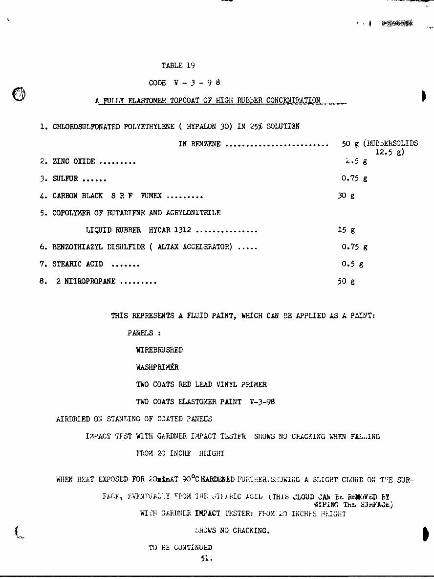
TABLE 19
CODE V - 3 - 9 8
0 A FUTLLY ELASTOMER TOPCOAT OF HIGH RUBBER CONCENTRATION
1. CHLOROSULFONATED POLYETHYLENE ( HYPALON 30) IN 25% SOLUTI@N
IN BENZENE ......................... 50 g (RUBbERSOLIDS12.5 g)
2. ZINC OXIDE ......... 2.5 g
3. SULFUR ...... 0.75 g
4. CARBON BLACK S R F FUMEX ......... 30 g
5. COPOLYMER OF BUTADIFNE -ND ACRYLONITRILE
LIQUID RUBBER HYCAR 1312 ............... 15 g
6. BENZOTHIAZYL DISULFIDE ( ALTAX ACCE.LEFATOR) ..... 0.75 g
7. S•T•AIC ACID ....... 0.5 g
8. 2 NITROPROPANE ......... 50 g
THIS REPRESENTS A FLUID PAINT, WHICH CAN BE APPLIED AS A PAINT:
PANELS
WIREBRUSHED
WASHPRIiAR
TWO COATS RED LEAD VINYL PRIMER
TWO COATS ELASTOMER PAINT V-3-98
AIRDRIED ON STANLING OF COATED ?ANfES
IAPACT TE.ST WITH GARDNER IAPACT TESTER SHOWS NO CFACKING WHEN FALL.ING
FROM 20 INCHF HEIGHT
WHFN HEAT EXPOSED FOR 2OminAT 90 0CHARDiZED FUR-hER.S!)WING A SLIGHT CLOUD ON T':E SUR-
FACE, BVF.NFALmY "i-OM ThE uT ii~C ACIDi (Thlb CLOUD CAN br, RkEOVED BYWIPING Thr S6JhFACt.)
WI gil GAEDNE.R IMPACT I'ESTER: FJOM Ž9 INCI4?S FI.-GHT
LHOWS NO CRACKING.
TO BE CONTINUED51.

V. CONCLUSION- THE PRLSLNT STATUS OF THE DMVELOPMENT.
At this time we feel that the base treatment is in good condition.
it consists of the following aspects:
a) Removal of all oxidized and corroded layers, creating a newly erposed surface,
by wire brushing or by sand / grit blasting.
b) Chemically reacting all parts of the surface, including the cavities of the
surface profile, by the application of a chemical treatment of low viscosity which
will not have difficulty in penetrating the cavities. This can be done, for instance,
by some selected form of a pickling solution. In order to increase the penetration
in the cavities, the driving out of air from the cavities, and the degree of chemical
reaction with the steel, it is recommendable to utilize the solution at an elevated
temperature. In the laboratory, and on smaller parts in the shop, this can be done
by hot spraying of the pickling solution. The reaction surface is then to be allowed
to dry before the next treatment is applied.
At this stage the surface is 'miformly chemically reacted and reactive for
further reactive coating applications.
c) Application of a primer coat of low viscosity, such as the wash-primer, or
one of its rodifications. This coat will penetrate into the cavities and chemically
react with the earlier treatment. With the application of this primer coat, the
metal substrate is freed from unreacted areas within the surface, which would present
a starting point of corrosion as well as loss of adhesion.
It is to be mentioned that in our experience the specification wash-prirer
is not the only successful reactive, low-viscous primer. Many others are known to us
and can be developed further for ship application.
d) It is nenessary to form a uniform primer coat all over the surface which can
represent the base for the top coat system. Hereby, the viscosity of the primer
material can be increased gradually. That means when, for instance, two coats of a
52.

0 primer are being applied, it is possible to apply the first one in a somewhat more
diluted form than the second coat. The purpose is to give the first coat a better
flow into the prepared and chemically pre-reacted cavities. ;t would be the ideal
state when these cavities could be brought to where they no longer represent a
separate factor. The second primer coat can then completely cover the whole system
and represent the base for the top coat system.
Since we are trying here to produce a solid foundation and an adhesion base
for the whole system, it appears recommendable that this primer should also be based
on a reactive pigment. For example, we used red lead vinyl primer or zinc chromate
vinyl primer or one coat of each. That here a reaction with the earlier treatment
still can take place at all - as seen in the still increasing stripping weight -
indicates that the wash primer coat alone did not fully eliminate the reactivity of
the substrate. The last primer coat should no longer be able to produce an increase
becaus&e it should no longer be in contact with the steel surface itself.
But since these more viscous primers also show an increased tendency to
retain solvents, they produce the most solid base for the subsequent coatings when
a short application of an elevated temperature could be provided. For smaller
parts this does not represent a difficulty. For the outside of the ship it is still
to be studied whether or not a short hot air blast might accomplish the desired
effect.
After the primer layers are properly applied and dried, the ground foundation
for any coating system is completed; and it is our feeling from our tests that
afterwards the adhesion under supersonic vibration should not cause any special
difficulties.
THE TOP COATS.
When some ten or fifteen years ago the vinyl systtem replaced more and more the
S earlier oleoresinous and alkyd systems, it was generally assumed that their main
53.

feature is based on the characteristics of the particular type of polyvinyl resin
used in a coating. And there is without doubt some merit to this approach. But the
main basis for this success of the vinyl system over the earlier system is in another
fact: In any of the earlier systems, the coating material contained very small amounts
of pre-polymerized matter. In oil based coatings the content was minute. Then, in
oil modified alkyds the per cent of initial polymer phase was somewhat higher, but the
further progress of the polymerization in the applied coating was still slow; and the
hardening of the coating itself and the resistance against saltwater were still
limited. When the vinyl system came, it was the first system where a pre-polymerized
resin was used in solution;and upon evaporation of the solvent, therefore, a film was
obtained which had a considerably higher ratio of polymer matter than in the earlier
coatings. But, here, still the final cross-linking or insolubilization and formation
of a dense polymer film progressed very slowly. That is why the final coat with a
combined vinyl and alkyd paint showed a considerably denser coating. We have worked
on this system some years ago and there can be no doubt that thii vinyl alkyd paint
represented at that time the most highly cross-linked and densest c-ating which has
been available. But still there was the fact to oe faced that the alkyd component
was not alkali resistant, and under exposure to the electrical effect of cathodic
protection, it failed gradually on ship surfaces which were under cathodic protection.
The further development therefore must :
a) continue to aim for highly polymerized coatings, or for coatings which after
application continue to be cross-linked into the densest possible form without being
saponified under cathodic protection.
b) aim to include pre-polymerized materials for the group referred to as elastomers
In connection with additives which will allow further cross-linking the applied
elastomer.
How far did we get with these two problems? This project director faced the
54.

problem of introducing polymer matter into oleaginous vehicles before their application.
some years ago. It was found that it is possible to air-blow oil at elevated
temperature to gelation, that is, to such a high state of polymor content that the
oil becomes insoluble, strongly swelling, and , at room temperature, strongly coherent,
even extensible, like a rubbery compound. By continuing heating these gels with a
metalsoap compound, the gels disperse into a fluid appearance, where they can be
further dispersed with solvents in a varnish-like form. They maintain their viscosity
in this form for years, but they still contain a high percentage of polymer matter.
lIen these pre-gelled oils are applied, they are high in polymer content from the
application on, and they can continue to harden by a combination cf further
polymerisation and of surface oxidation of their applied coatings. In this form the
coatings are highly coherent and resistant to seawater even under an electric current.
This offered one possible approach.
The project director had observed also that metalorganic fluids can be produced
based on one or more different metal components. These metalorganic compounds can be
produced under vacuum distillation, whereby they are freed from low-temperature-
volatile components and distill at about 2 -. Hg. pressure at 2800 - 3000 Centigrade.
These highly stable compounds can De cross-linked further with a metalorganic epoxide
and turn into high-temperature-stable resins, which can be redispersed and introduced
into coatings. They can be combined also with pre-gelled oil, as described above.
Combining these new components under pigmentation, etc., the first of our
experimental paints has been obtained. Its drying can further be modified by a Joint
short heat exposure of these paints with a titanate epoxide, whereby the gel matter
is increased. These paints turn into a dense polymer form and are stable under
saltwater and under supersonic vibration. Only at a later stage of the past year, it
was observed from exposure to a strong transducer at the Applied Science Laboratory in
Brooklyn, that we had reached such a high degree of cross-linkage that the dilect
55
S _ . .. . .... .. . ... . .. . . . .- 7L ....... li II I IIoIoI

bombardment with the ultrrsonl.c enerj-y ceused a !ab-ss-iike piercini- in the center
points of +.he radiation T"here w-s no adhesion faiiure of any kind in ..he cavitation Iarea; but we htve discussed Elready how this coherence resistance against this energy
can be increased-
A different form of new paint deveiopment this year refer-cad to a combination
of progressingly cross-linking resinous vehicles with an elastomer which represents
a chlorosulfonated polyethylene k Hypalon 30) which has a greater solubility than
other elastomers such as are classified as synthetic rubbers, in particular much
higher solubility than neoprene The experimental paints which we have prepared
some months ago on this basis were based either on & pigmentation of an alkyd solution
or of a pre-gelled oil and by then introducing a 25% dispersion of the polyethylene
derivative and further cross-linking the whole material by the introduction of a
phenolic resin-tung oil varnish. Under the addition of a very small amount of any
one of the common "accelerators" for synthetic rubber, the whole applied coating
could be cured re dily and was resistant against salt water and against supersonic
vibration. Here again only the direct exposure to the strong energy emission of the
transducer at the U S. baval Applied Science Laboratory in brooklyn showed us that
we might have gone too far in the cross-linking, since the factor of the energy
bombardment caused here some piercing phenomena also No f'ailire of adhesion
took place to any extent.
We are working, therefore, at this time to extend the coherence in these
high polymer coating systems, which have not shown adhesion difficulties. It might
appear possible to increase the coherence by less extensively pursuing the cross-
linkage of the paint materials. This again, however, might cause speedy loss of
e adhesion such as occurred at the start of the project; or, when a gradual effective
Scross-linking would take place after paint application, it might result in gradual
loss of coherence, which is not desirable. Therefore, a new experimental coating
A6.

might be developed where a new component is introduced into the coatings which have been
f developed in this report, with this new component heving the properies 6a) of not Pelling
at all without interfering with the progress of the gelation of the coating itself, and
(b) golling under such different conditions that its own gelling would not take place
during the curing of the experimental paint. Some exploratory tests have been made
with respect to using non gelling rdditives, such as by incorporating some form og
"plasticizer"such as tricresyl ohosphate. Such a combination with the experimental paints
of this project have stood up vreli under saltwater exposure with supersonic vibration.
A new , different approach t'o the problem of obtaining good adhesion as well as
good coherence in an elastomeric paint w&n made with exploratory tests introducing
a synthetic rubber in a low-polymer, still-fluid form into a dispersion of a highly
cross-linked form of another syrthetic elastomer. In this case a liquid form of a
butadiene-acrylonitrile rubber, having a medium high acrylonitrile content, was
combined with a dispersion of the chlorosulfonated polyehtylene, such as used in
earlier tests of this report. That means, for instance, by weight one-half of the
chlorosulfonated polyethylene (Hypalon 30 ) was replaced by liquid HYCAR 1312. This
combination of two elastomers ir widely different states of crosslinkage was incorporated
in an experimental paint and showed during more than 400 hours exposure to 5% saltwater
under supersonic vibration a very good stability. The coating stood up well under
impact tests also. and did not show loss of adhesion when after the impact test the
panels were returned to the saltwater exposure under vibration conditions.
inother new approach included the incorporation of rubber accelerators, or the
crosslinking with titanate epoxide into elastomeric test points. In the very last
work on the exploratory tests the Hypalon type experimental test paints were modified
further by omitting the phenolic resin-tungoil component. The paint was here used
2s a rubber-like paint compound based on the two different polymer state elastomers
as just outlined above. Hereby, sulfur was introduced in the pigmented elastomer
compound as a"vulcanising"agent.
57-

In applying the new elastomer type paints, the substrate weis prepared in
accordance with the recommendations outlined earlier, on pages 52-53 of this report.
The tests under 5% saltwater and vibration conditions were very promising with these
new types of elastomer coatings.
Basically, in comparing these new elastomer coatings of this project with the
conventional commercial neoprene coatings, the difference is that a dispersion of
s neoprene necessarily produces a low e.astomer concentratiorn in the solution, therefirA
requiring a considerable number of coats in building up a coating system, and each
coat has the tendency to retain solvent residues in the coating. The new coatings,
on the other hand, have a high elestomer concentration since they contain partially
an elastomer which can be- dispersed in an apprcximate 30% solution. The other
elastomer is for itself liquid Therefore, they produce a heavier film thickness
in fewer coats. These high elastomer paint coatings on steel can be expected 4to produce the required conditions in the dome area also, without requiring extensive
structural modifications of this area.
3..
58.
M mam.

APPENDIX
a) REFEW6CS CITE-D
-. a m U nl ___ n__ _l I mI W1r "oit ^L'n £ F ,..r '- s
%-, &"0U.,A~ Mo L1J~jCU, =.St. a&UJI Lyr,YU fJ.#J. -uwuzard~ w UK4.LW CyrO1 r i1!timALKYL TIfANATES ON ELASTOUERIC COATING MATLiIAuS", in JOURNAL OF PAINT TFZHNOLOGY-OFFICIAl DIGEST, Vol. 38, No. 492, pages 37-42 (January 1966).
(2) Kronstein, M., Carroad, N. R. and Byrd, J. J., "THE GELATION ZWECT OF TETRA ALKYLTITANATES ON THE FORMATION OF POLYMER RESINS", in OFFICIAL DIGEST (of the Federationof Societies for Paint Technology), Vol. 37, No. 482, pages 284-301 (March 1965)
(3) Kronstein, I. , "Solubilizing Insoluble Gelatinized Oils",U.S.Patent 2 476 879, July 19, 1949.
(4) Kronstein, I. *Solubilizing at beast Partially Insoluble and Gelatinous Waxesand Oils", U. S. Patent 2 568 550 and 551 , September 18, 1951.
(5) Kronstein, I,, "Stable Dispersions of Oil Gels", in PAINT AND VARNISH PRODUCTIONmagazine, Vol. 50, No. 4 (April 1960).
(6) Kronstein, N. and Kapfer, W.H., "Coaplex Alkyl Titanate Derivatives" ,
U. S. Patent 3 196 166, July 20, 1965.
(7) Kronstein, U., Von Burgsdorff, W. A., Hanan, N. and Weir, D. L., "UtilizingMolybdenum Compounds in the Surface Protection of Steel", in pre-print book"Papers Presented at the Atlantic City Meeting", of the American Chemical Sr&ciety,Division of Organic Coatings and Plastics Chemistry, Vol. 25, No. 2, pages 173-191,(September 1965).
b) SPECIFICATION PAINT MATERIALS USLD IN THi PROJECT
TT-R-266 a, RESIN ALKYD, SOLUTION, TYPE I:LONG OIL SOYA-MODIFIED.
ML-V-l137 A, VARNISH, ELECTRICAL, INSULATING.
M!--P-15328B (FORMULA 117) PRIMER, PRE-TREAThLNT FOR MUTALS ( WASH-PRIMeR).
MIL-P-15929B (FORMULA 119) PRIMER COATING, SHIPBOARD, VINYL-RED LEAD.
MIL-P-15930B (FORMULA 120) PRIMER, VIBNYj-ZIBC CHiROMATE TYPE.
MIL-P-15931B (FOIRULA 121/63) PAINT ANTIFOULING, VIB)L., RED.
MIL-E-15936B (FOR*ULA 122-27) ENAMEL EXTERIOR URAY, VI•NL-ALKYD
MIL-P-22299 (SHIPS) (FORMULA 134) PAINT ANTIFOULING, POLYISOBUTYLUCE..
59.
- . . . .t l l i

APPENDIX •CONTINUWD)
c) PROPRIETARY IATUL.AkS
The commercial aaterials listed bplow have been used in the work of this project:
ACTIVATED CARBON H-21-71-h UWION OPARBiD; CHWICALS C,.
ALTAX RUBBER ACCELERATOR (Benzothiazyi disulfide) R.T.VANDE•RILT CO.,Inc.
ALUMINUM 5 XD REYNOLDS METALS COMPANY, PIGMENT DIVISION.
AROPLAZ 1266 M 70 (Long oil soyabean modified according to TT-R-266 a) ARZHER-DANIELS-MIDLAND
CARBON BLACK SPF FUMEX COLUMBIAN CARBON CO.
CASTUNG-103 (Dehydrated castor oil) BAKER CASTOR OIL COMPANY
EPOXIDE-206 (Vinyl cyclohexene dioxide) UNION CARBON CHEMICALS CO.
EPONOL 55 RESIN SHELL CHEMICAL CORPORATIONHYCAR 1312 (Liquid Rubber) (Low mol•_-lI- copolymer of butadiene and scrylonitrile)
THE B. F. GOODRICH CHEIICAL CO.
HYPALON 30 (Chiorosulfonated polyethylene) E. 1. DU PONT DE NkNOURS & CO. ,ELASTOMERCHEMICALS.
MAPICO RED ( synthetic iron oxides) COLUMBIAN CARbON CO.
N-39 COLD BOND (Comercial neoprene paint) GATES ENGINEERING COMPANi
PHENOLIC RESIN VARNISH SYNTHITE AC-8 and AC-24 ( clear air drying varnishes)according to MIL-V-1137 A. JOHN C DOLPH COMPANY.
UNADS ACCOLERATOR ('letra methyl thiuram monosulfide) R.T.VANDERMILT CO,INC.ZINC OCTOATE, BASIC: SILICURE Z-775 NUODEX PRODUCTS DIVISION OF HEYDEN NEWPORT
CHEMICAL CORPORATION.ZINC DUST #22. NEW J-RSEY ZINC COMPANY.
d) COMMERCIAL £"UIPMEtAT USED
Brush Surface Analyzer, Modle BL-103. BRUSH ELETRONICS CO., CLEVEWAUL1, OHIO.
SONOGEN ILGI-40 ýUltrasonic generator & tank) Branson Instruaents,Inc.,Stamford,Conn.
SONIFIER MODEL S-125. HEAT SYSTEMS COMPANY, Melville, L.I., N.Y.
60.