Embed Size (px)
Citation preview
1/4
I. Confirmation of the reactor conditions 1. Temperatures inside the reactors
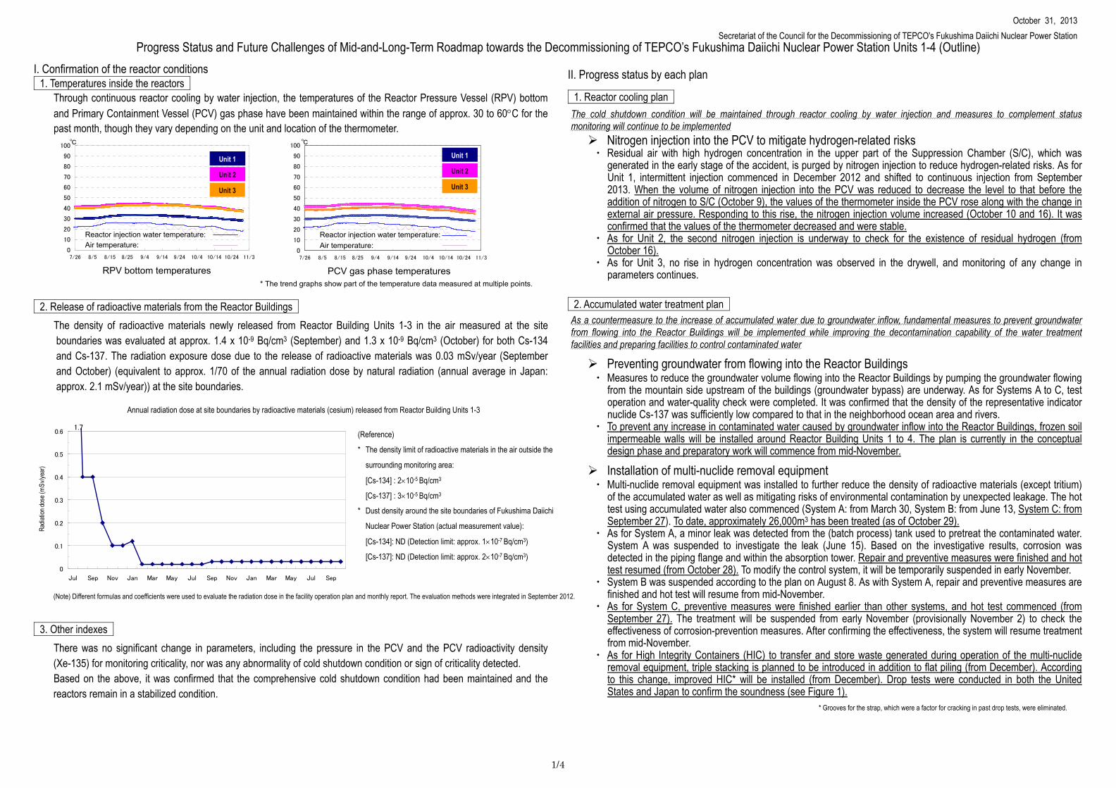
Through continuous reactor cooling by water injection, the temperatures of the Reactor Pressure Vessel (RPV) bottom and Primary Containment Vessel (PCV) gas phase have been maintained within the range of approx. 30 to 60C for the past month, though they vary depending on the unit and location of the thermometer.
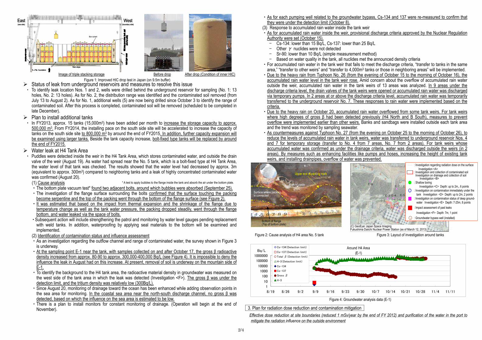
2. Release of radioactive materials from the Reactor Buildings The density of radioactive materials newly released from Reactor Building Units 1-3 in the air measured at the site boundaries was evaluated at approx. 1.4 x 10⁻⁹ Bq/cm3 (September) and 1.3 x 10⁻⁹ Bq/cm3 (October) for both Cs-134 and Cs-137. The radiation exposure dose due to the release of radioactive materials was 0.03 mSv/year (September and October) (equivalent to approx. 1/70 of the annual radiation dose by natural radiation (annual average in Japan: approx. 2.1 mSv/year)) at the site boundaries.
3. Other indexes There was no significant change in parameters, including the pressure in the PCV and the PCV radioactivity density (Xe-135) for monitoring criticality, nor was any abnormality of cold shutdown condition or sign of criticality detected. Based on the above, it was confirmed that the comprehensive cold shutdown condition had been maintained and the reactors remain in a stabilized condition.
II. Progress status by each plan
1. Reactor cooling plan
The cold shutdown condition will be maintained through reactor cooling by water injection and measures to complement status monitoring will continue to be implemented Nitrogen injection into the PCV to mitigate hydrogen-related risks ・ Residual air with high hydrogen concentration in the upper part of the Suppression Chamber (S/C), which was
generated in the early stage of the accident, is purged by nitrogen injection to reduce hydrogen-related risks. As for Unit 1, intermittent injection commenced in December 2012 and shifted to continuous injection from September 2013. When the volume of nitrogen injection into the PCV was reduced to decrease the level to that before the addition of nitrogen to S/C (October 9), the values of the thermometer inside the PCV rose along with the change in external air pressure. Responding to this rise, the nitrogen injection volume increased (October 10 and 16). It was confirmed that the values of the thermometer decreased and were stable.
・ As for Unit 2, the second nitrogen injection is underway to check for the existence of residual hydrogen (from October 16).
・ As for Unit 3, no rise in hydrogen concentration was observed in the drywell, and monitoring of any change in parameters continues.
2. Accumulated water treatment plan As a countermeasure to the increase of accumulated water due to groundwater inflow, fundamental measures to prevent groundwater from flowing into the Reactor Buildings will be implemented while improving the decontamination capability of the water treatment facilities and preparing facilities to control contaminated water
Preventing groundwater from flowing into the Reactor Buildings ・ Measures to reduce the groundwater volume flowing into the Reactor Buildings by pumping the groundwater flowing
from the mountain side upstream of the buildings (groundwater bypass) are underway. As for Systems A to C, test operation and water-quality check were completed. It was confirmed that the density of the representative indicator nuclide Cs-137 was sufficiently low compared to that in the neighborhood ocean area and rivers.
・ To prevent any increase in contaminated water caused by groundwater inflow into the Reactor Buildings, frozen soil impermeable walls will be installed around Reactor Building Units 1 to 4. The plan is currently in the conceptual design phase and preparatory work will commence from mid-November.
Installation of multi-nuclide removal equipment ・ Multi-nuclide removal equipment was installed to further reduce the density of radioactive materials (except tritium)
of the accumulated water as well as mitigating risks of environmental contamination by unexpected leakage. The hot test using accumulated water also commenced (System A: from March 30, System B: from June 13, System C: from September 27). To date, approximately 26,000m3 has been treated (as of October 29).
・ As for System A, a minor leak was detected from the (batch process) tank used to pretreat the contaminated water. System A was suspended to investigate the leak (June 15). Based on the investigative results, corrosion was detected in the piping flange and within the absorption tower. Repair and preventive measures were finished and hot test resumed (from October 28). To modify the control system, it will be temporarily suspended in early November.
・ System B was suspended according to the plan on August 8. As with System A, repair and preventive measures are finished and hot test will resume from mid-November.
・ As for System C, preventive measures were finished earlier than other systems, and hot test commenced (from September 27). The treatment will be suspended from early November (provisionally November 2) to check the effectiveness of corrosion-prevention measures. After confirming the effectiveness, the system will resume treatment from mid-November.
・ As for High Integrity Containers (HIC) to transfer and store waste generated during operation of the multi-nuclide removal equipment, triple stacking is planned to be introduced in addition to flat piling (from December). According to this change, improved HIC* will be installed (from December). Drop tests were conducted in both the United States and Japan to confirm the soundness (see Figure 1).
0
10
20
30
40
50
60
70
80
90
100
7/26 8/5 8/15 8/25 9/4 9/14 9/24 10/4 10/14 10/24 11/3
℃
PCV gas phase temperatures * The trend graphs show part of the temperature data measured at multiple points.
RPV bottom temperatures
Progress Status and Future Challenges of Mid-and-Long-Term Roadmap towards the Decommissioning of TEPCO’s Fukushima Daiichi Nuclear Power Station Units 1-4 (Outline)
October 31, 2013 Secretariat of the Council for the Decommissioning of TEPCO's Fukushima Daiichi Nuclear Power Station
Annual radiation dose at site boundaries by radioactive materials (cesium) released from Reactor Building Units 1-3
(Note) Different formulas and coefficients were used to evaluate the radiation dose in the facility operation plan and monthly report. The evaluation methods were integrated in September 2012.
(Reference)
* The density limit of radioactive materials in the air outside the
surrounding monitoring area:
[Cs-134] : 210-5 Bq/cm3
[Cs-137] : 310-5 Bq/cm3
* Dust density around the site boundaries of Fukushima Daiichi
Nuclear Power Station (actual measurement value):
[Cs-134]: ND (Detection limit: approx. 110-7 Bq/cm3)
[Cs-137]: ND (Detection limit: approx. 210-7 Bq/cm3)
* Grooves for the strap, which were a factor for cracking in past drop tests, were eliminated.
0
10
20
30
40
50
60
70
80
90
100
7/26 8/5 8/15 8/25 9/4 9/14 9/24 10/4 10/14 10/24 11/3
℃
Reactor injection water temperature:
Unit 1
Unit 2
Unit 3
Air temperature:
Unit 1
Unit 2
Unit 3
Reactor injection water temperature: Air temperature:
0
0.1
0.2
0.3
0.4
0.5
0.6
Jul Sep Nov Jan Mar May Jul Sep Nov Jan Mar May Jul Sep
Radia
tion d
ose (
mSv
/year
)
1.7
2/4
Status of leak from underground reservoirs and measures to resolve this issue ・ To identify leak location Nos. 1 and 2, wells were drilled behind the underground reservoir for sampling (No. 1: 13
holes, No. 2: 13 holes). As for No. 2, the distribution range was identified and the contaminated soil removed (from July 13 to August 2). As for No. 1, additional wells (5) are now being drilled since October 3 to identify the range of contaminated soil. After this process is completed, contaminated soil will be removed (scheduled to be completed in late December).
Plan to install additional tanks ・ In FY2013, approx. 15 tanks (15,000m3) have been added per month to increase the storage capacity to approx.
500,000 m3. From FY2014, the installing pace on the south side site will be accelerated to increase the capacity of tanks on the south side site to 800,000 m3 by around the end of FY2015. In addition, further capacity expansion will be examined using larger tanks. Beside the tank capacity increase, bolt-fixed type tanks will be replaced by around the end of FY2015.
Water leak at H4 Tank Area ・ Puddles were detected inside the weir in the H4 Tank Area, which stores contaminated water, and outside the drain
valve of the weir (August 19). As water had spread near the No. 5 tank, which is a bolt-fixed type at H4 Tank Area, the water level of that tank was checked. The results showed that the water level had decreased by approx. 3m (equivalent to approx. 300m3) compared to neighboring tanks and a leak of highly concentrated contaminated water was confirmed (August 20). (1) Cause analysis ・The bottom plate vacuum test* found two adjacent bolts, around which bubbles were absorbed (September 25). ・The investigation of the flange surface surrounding the bolts confirmed that the surface touching the packing
become serpentine and the top of the packing went through the bottom of the flange surface (see Figure 2). ・It was estimated that based on the impact from thermal expansion and the shrinkage of the flange due to
temperature change as well as the tank water pressure, the packing dropped steadily, went through the flange bottom, and water leaked via the space of bolts.
・Subsequent action will include strengthening the patrol and monitoring by water level gauges pending replacement with weld tanks. In addition, waterproofing by applying seal materials to the bottom will be examined and implemented.
(2) Identification of contamination status and influence assessment ・As an investigation regarding the outflow channel and range of contaminated water, the survey shown in Figure 3
is underway. ・At the sampling point E-1 near the tank, with samples collected on and after October 17, the gross β radioactive
density increased from approx. 80-90 to approx. 300,000-400,000 Bq/L (see Figure 4). It is impossible to deny the influence the leak in August had on this increase. At present, removal of soil is underway on the mountain side of E-1.
・To identify the background to the H4 tank area, the radioactive material density in groundwater was measured on the west side of the tank area in which the leak was detected (Investigation <F>). The gross β was under the detection limit, and the tritium density was relatively low (300Bq/L).
・Since August 20, monitoring of drainage toward the ocean has been enhanced while adding observation points in the sea area for monitoring. In the coastal sea area near the north-south discharge channel, no gross β was detected, based on which the influence on the sea area is estimated to be low.
・There is a plan to install monitors for constant monitoring of drainage. (Operation will begin at the end of November).
・As for each pumping well related to the groundwater bypass, Cs-134 and 137 were re-measured to confirm that they were under the detection limit (October 8).
(3) Response to accumulated rain water inside the tank weir ・As for accumulated rain water inside the weir, provisional discharge criteria approved by the Nuclear Regulation
Authority were set (October 15). - Cs-134: lower than 15 Bq/L, Cs-137: lower than 25 Bq/L - Other γ nuclides were not detected - Sr-90: lower than 10 Bq/L (simple measurement method) - Based on water quality in the tank, all nuclides met the announced density criteria
・For accumulated rain water in the tank weir that fails to meet the discharge criteria, “transfer to tanks in the same area,” “transfer to other weirs” and “transfer to 4,000m3 tanks or those in neighboring areas” will be implemented.
・Due to the heavy rain from Typhoon No. 26 (from the evening of October 15 to the morning of October 16), the accumulated rain water level in the tank weir rose. Amid concern about the overflow of accumulated rain water outside the weir, accumulated rain water in the tank weirs of 13 areas was analyzed. In 9 areas under the discharge criteria level, the drain valves of the tank weirs were opened or accumulated rain water was discharged via temporary pumps. In 2 areas at or above the discharge criteria level, accumulated rain water was temporarily transferred to the underground reservoir No. 7. These responses to rain water were implemented based on the criteria.
・Due to the heavy rain on October 20, accumulated rain water overflowed from some tank weirs. For tank weirs where high degrees of gross β had been detected previously (H4 North and B South), measures to prevent overflow were implemented earlier than other weirs. Banks and sandbags were installed outside each tank area and the trend was monitored by sampling seawater.
・As countermeasures against Typhoon No. 27 (from the evening on October 25 to the morning of October 26), to reduce the levels of accumulated rain water in tank weirs, water was transferred to underground reservoir Nos. 4 and 7 for temporary storage (transfer to No. 4 from 7 areas, No. 7 from 2 areas). For tank weirs whose accumulated water was confirmed as under the drainage criteria, water was discharged outside the weirs (in 2 areas). By measures such as enhancing facilities like pumps and hoses, increasing the height of existing tank weirs, and installing drainpipes, overflow of water was prevented.
3. Plan for radiation dose reduction and contamination mitigation
Effective dose reduction at site boundaries (reduced 1 mSv/year by the end of FY 2012) and purification of the water in the port to mitigate the radiation influence on the outside environment
Figure 1: Improved HIC drop test in Japan (on 9.5m buffer) Before drop After drop (Condition of inner HIC)
Figure 2: Cause analysis of H4 area No. 5 tank
Figure 4: Groundwater analysis data (E-1)
* A test to apply bubbles to the flange inside the tank and absorb the air under the bottom plate.
Image of triple stacking storage
Upper end of packing mark
Mark of paste
Rust Rust
Surface where packing is connected
Bottom of flange (Top of bottom plate)
East(sea side)
West(boundary side)
Rain slope
Floor plate: Width 36000 x length 200000
Pile foundation
Box culvert
East(sea side)
West(boundary side)
Rain slope
Floor plate: Width 36000 x length 200000
Pile foundation
Box culvert
Figure 3: Layout of investigation around tanks
E-7 E-8
E-3 E-4 E-5
C-3 C-4 C-5 C-6
C-1 C-2
D-2
D-1
E-1
E-2
F-1
E-6
: Investigation regarding radiation dose on the surfaceInvestigation <A>
: Investigation and collection of contaminated soilInvestigation on drainage and collection of soil
Investigation <B>: Shallow boring
Investigation <C> Depth: up to 2m,, 6 points: Investigation on contamination immediately under the
tank Investigation <D> Depth: up to 2m, 2 points: Investigation on contamination status of deep ground-
water Investigation <E> Depth: 7-25m, 8 points: Impact assessment of past leaks
Investigation <F> Depth: 7m, 1 point: Groundwater bypass well (installed)
(C) GeoEye/ Japan Space Imaging Fukushima Daiichi Nuclear Power Station (as of March 12, 2013)
Around H4 Area(E-1)
1
10
100
1000
10000
100000
1000000
8/19 8/26 9/2 9/9 9/16 9/23 9/30 10/7 10/14 10/21 10/28 11/4 11/11
Cs-134(Detection limit)
Cs-137(Detection limit)
Total β(Detection limit)
H-3(Detection limit)
Cs-134
Cs-137
全β
H-3
Bq/L
Gross β
3/4
Measures to address the issue of increased radioactive material density in groundwater on the sea side and in seawater
・ Analytical results of data e.g. concerning density and water levels of groundwater on the east (sea) side of the Reactor Buildings showed that contaminated groundwater had soaked into the seawater.
・ The density of cesium in seawater inside the Unit 2 intake silt fence increased to 830 Bq/L (October 9), but has since been decreasing since October 11. It is estimated that this was caused by contaminated water in soil being pushed out by ground improvement work around the points of high-density contaminated water leakage detected previously.
・ In seawater outside the port (at the east side of the port entrance), Cs-137 was detected (October 8: 1.4 Bq/L, October 18: 1.6 Bq/L). However, sampling data other than these two days were under the detection limit (October 28: ND (detection limit: 0.70Bq/L)).
・ Within the port, for gross β and tritium, no significant change was detected in recent data, while a low level of cesium was detected. Nor was any significant increase detected in offshore measurement results.
・ As immediate measures to prevent expansion of the contamination to sea, the following shall be implemented: (1) Preventing leakage of contaminated water ・Underground soil improvement behind the bank protection at the cooling water intake to prevent expansion of radioactive materials.
(Between Units 1 and 2: completed on August 9; between Units 2 and 3: from August 29 and scheduled for completion early November; between Units 3 and 4: from August 23 and scheduled for completion mid-November)
・Pumping of groundwater in contaminated areas Catchment pits and well points (compulsory pumping equipment by vacuuming) were installed to reduce the groundwater level. Between Units 1 and 2, by pumping groundwater, its water level will go below the highest level of underground soil improvement (O.P. + 2.20m). Between Units 2 and 3 and 3 and 4 respectively, by operating well points, contaminated water might be drawn from the seawater piping trench which includes highly concentrated contaminated water, and the contamination may expand. Accordingly, the well points will not be operated until completion of underground soil improvements on the sea side and water-quality monitoring of groundwater will be continued. (Catchment pits: (Between Units 1 and 2 only) From August 9, the transport of water commenced. Well points: (Between Units 1 and 2) From August 15, part of the transport of water commenced, and from August 23, full transport of water commenced. (Between Units 2 and 3) Preparation for operation was completed. (Between Units 3 and 4) Preparation for operation was completed.)
(2) Isolating groundwater from the contamination source ・Enclosure by the mountain side underground soil improvement
(Between Units 1 and 2: Commenced from August 13 and scheduled for completion at the end of December Between Units 2 and 3: Commenced from October 1 and scheduled for completion early December Between Units 3 and 4: Commenced from October 19 and scheduled for completion at the end of December)
・To prevent ingress of rainwater, the ground surface of the enclosed area by underground soil improvement will be paved with asphalt (to commence early November)
(3) Removing the contamination source ・Removal and closure of contaminated water such as branch trench (completed on September 19)
Contaminated water in the branch trench of Unit 2 and vertical shaft B to the branch trench was transferred to the Unit 2 Turbine Building (August 22-24), whereupon the trench was closed (August 29 – September 19).
・Purification and removal of contaminated water in the main trench (Units 2 and 3: Purification will commence mid-November)
・ In the review committee, consisting of experts to examine the factors contributing to the increased density of radioactive materials in seawater within the port and verify the measures implemented by TEPCO, analysis of the groundwater flow and evaluation on the transfer of radioactive materials are conducted (1st meeting: April 26, 2nd: May 27, 3rd: July 1. 4th July 23, 5th: August 16, 6th: October 25).
4. Plan for fuel removal from the spent fuel pools
Work toward removing spent fuel from the pool is steadily progressing while ensuring seismic capacity and safety. In particular, efforts are being made to achieve an early start and complete the removal of spent fuel from the Unit 4 pool (planned to commence in November 2013 with completion scheduled for around the end of 2014)
Main works toward removing spent fuel at Unit 4 ・ In the mid-and-long term roadmap, the major goal is to remove spent fuel from the ealiest Unit’s spent fuel pool
within two years of completion of Step 2 (by December 2013). ・ Preparatory work such as removal of rubble and installation of a cover for fuel removal is underway and removal
of fuel from the spent fuel pool of Unit 4 will commence from mid-November. ・ In the spent fuel pool, 1,533 rods (spent fuel: 1,331 rods, new fuel: 202 rods) are currently stored. The fuel
removed from the spent fuel pool will be transferred to the “common pool” in a separate building from Unit 4 to store them under more stable conditions. The removal is scheduled for completion around the end of 2014.
・ For removal from the spent fuel pool, the rods will be taken out one by one after confirming their soundness, packed in containers for transport within the spent fuel pool (22 rods per container), and transported to the common pool. Two containers will be used for transport to simultaneously work both for the spent fuel pool and the common pool.
・ At the same time, to ensure a space in the common pool for storing the fuel removed from the spent fuel pool, fuel having been stored in the common pool since before the disaster is steadily transferred to the temporary storage facility for dry casks.
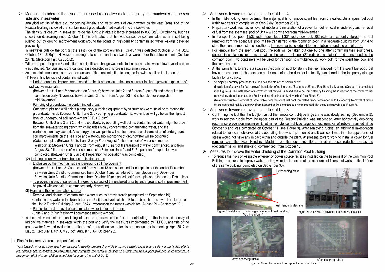
・ The major preparatory process for fuel removal to date are as shown below: (Installation of a cover for fuel removal) Installation of ceiling crane (September 25) and Fuel Handling Machine (October 14) completed (see Figure 5). The installation of a cover for fuel removal is scheduled to be completed by finishing the inspection of the cover for fuel removal, overhanging crane, and Fuel Handling Machine (early November) (see Figure 6). (Removal of rubble) Removal of large rubble from the spent fuel pool completed (from September 17 to October 2). Removal of rubble on the spent fuel rack is underway (from September 30, simultaneously implemented with the fuel removal) (see Figure 7).
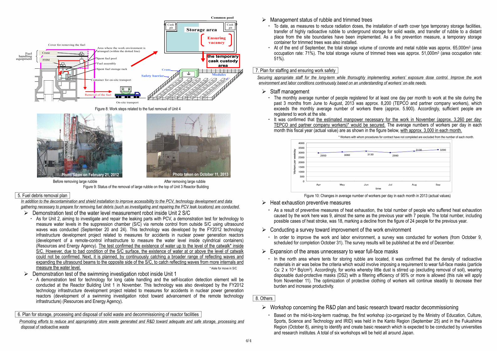
Main works toward removing spent fuel at Unit 3 ・ Confirming the fact that the top jib mast of the remote control-type large crane was slowly leaning (September 5),
work to remove rubble from the upper part of the Reactor Building was suspended. After horizontally deploying recurrence prevention measures to other remote control-type large cranes, removal of rubble resumed since October 8 and was completed on October 11 (see Figure 9). After removing rubble, an additional investigation related to the steam observed at the operating floor was implemented and it was confirmed that the appearance of steam would not have any impact within and outside the plant. At present, toward work to install a cover for fuel removal and the Fuel Handling Machine on the operating floor, radiation dose reduction measures (decontamination and shielding) commenced (from October 15).
Measures to improve the water shielding of the Common Pool Building ・ To reduce the risks of losing the emergency power source facilities installed on the basement of the Common Pool
Building, measures to improve waterproofing were implemented at the apertures of floors and walls on the 1st floor of the same building (completed on September 30).
Overhanging crane
Fuel Handling Machine
Figure 6: Unit 4 with a cover for fuel removal installed
Figure 7: Absorption of rubble on spent fuel rack in Unit 4
Figure 5: Installation of overhanging crane and Fuel Handling Machine in Unit 4
Before absorving rubble After absorving rubble
4/4
5. Fuel debris removal plan
In addition to the decontamination and shield installation to improve accessibility to the PCV, technology development and data gathering necessary to prepare for removing fuel debris (such as investigating and repairing the PCV leak locations) are conducted. Demonstration test of the water level measurement robot inside Unit 2 S/C ・ As for Unit 2, aiming to investigate and repair the leaking parts with PCV, a demonstration test for technology to
measure water levels in the suppression chamber (S/C) via remote control from outside S/C using ultrasound waves was conducted (September 20 and 24). This technology was developed by the FY2012 technology infrastructure development project related to measures for accidents in nuclear power generation reactors (development of a remote-control infrastructure to measure the water level inside cylindrical containers) (Resources and Energy Agency). The test confirmed the existence of water up to the level of the catwalk* inside S/C. However, due to bad condition of the S/C surface, the existence of water at or above the level of catwalk could not be confirmed. Next, it is planned, by continuously catching a broader range of reflecting waves and expanding the ultrasound beams to the opposite side of the S/C, to catch reflecting waves from more internals and measure the water level.
Demonstration test of the swimming investigation robot inside Unit 1 ・ A demonstration test for technology for long cable handling and the self-location detection element will be
conducted at the Reactor Building Unit 1 in November. This technology was also developed by the FY2012 technology infrastructure development project related to measures for accidents in nuclear power generation reactors (development of a swimming investigation robot toward advancement of the remote technology infrastructure) (Resources and Energy Agency).
6. Plan for storage, processing and disposal of solid waste and decommissioning of reactor facilities
Promoting efforts to reduce and appropriately store waste generated and R&D toward adequate and safe storage, processing and disposal of radioactive waste
Management status of rubble and trimmed trees ・ To date, as measures to reduce radiation doses, the installation of earth cover type temporary storage facilities,
transfer of highly radioactive rubble to underground storage for solid waste, and transfer of rubble to a distant place from the site boundaries have been implemented. As a fire prevention measure, a temporary storage container for trimmed trees was also installed.
・ At of the end of September, the total storage volume of concrete and metal rubble was approx. 65,000m3 (area occupation rate: 71%). The total storage volume of trimmed trees was approx. 51,000m3 (area occupation rate: 51%).
7. Plan for staffing and ensuring work safety
Securing appropriate staff for the long-term while thoroughly implementing workers’ exposure dose control. Improve the work environment and labor conditions continuously based on an understanding of workers’ on-site needs.
Staff management ・ The monthly average number of people registered for at least one day per month to work at the site during the
past 3 months from June to August, 2013 was approx. 8,200 (TEPCO and partner company workers), which exceeds the monthly average number of workers there (approx. 5.900). Accordingly, sufficient people are registered to work at the site.
・ It was confirmed that the estimated manpower necessary for the work in November (approx. 3,260 per day: TEPCO and partner company workers)* would be secured. The average numbers of workers per day in each month this fiscal year (actual value) are as shown in the figure below, with approx. 3,000 in each month.
Heat exhaustion preventive measures ・ As a result of preventive measures of heat exhaustion, the total number of people who suffered heat exhaustion
caused by the work here was 9, almost the same as the previous year with 7 people. The total number, including possible cases of heat stroke, was 18, marking a decline from the figure of 24 people for the previous year.
Conducting a survey toward improvement of the work environment ・ In order to improve the work and labor environment, a survey was conducted for workers (from October 9,
scheduled for completion October 31). The survey results will be published at the end of December.
Expansion of the areas unnecessary to wear full-face masks ・ In the north area where tents for storing rubble are located, it was confirmed that the density of radioactive
materials in air was below the criteria which would involve imposing a requirement to wear full-face masks (particle Cs: 2 x 10⁻⁴ Bq/cm3). Accordingly, for works whereby little dust is stirred up (excluding removal of soil), wearing disposable dust-protective masks (DS2) with a filtering efficiency of 95% or more is allowed (this rule will apply from November 11). The optimization of protective clothing of workers will continue steadily to decrease their burden and increase productivity.
8. Others
Workshop concerning the R&D plan and basic research toward reactor decommissioning ・ Based on the mid-to-long-term roadmap, the first workshop (co-organized by the Ministry of Education, Culture,
Sports, Science and Technology and IRID) was held in the Kanto Region (September 25) and in the Fukushima Region (October 8), aiming to identify and create basic research which is expected to be conducted by universities and research institutes. A total of six workshops will be held all around Japan.
Figure 9: Status of the removal of large rubble on the top of Unit 3 Reactor Building
Photo taken on February 21, 2012 Photo taken on October 11, 2013 Before removing large rubble After removing large rubble
* Aisle for move in S/C
Figure 8: Work steps related to the fuel removal of Unit 4
* Workers with whom procedures for contract have not completed are excluded from the number of each month.
Figure 10: Changes in average number of workers per day in each month in 2013 (actual values)
キ ャス クピ ット
キャ ス クピ ッ ト貯 蔵 エ リア
空 き ス ペ ー ス
の 確 保
共用プール
構内移送
使用済燃料プール
使用済燃料貯蔵ラック
燃料取り出し用カバー作業環境整備区画(点線内)
燃料集合体
構内用輸送容器
クレーン
燃料取扱機
燃料取扱設備
燃料取り出し
クレーン
防護柵 モジュール
the temporary cask custody
area
Fuel handling
equipment FHM
Cover for removing the fuelArea where the work environment is arranged (within the dotted line)
Spent fuel pool
Fuel assembly
Spent fuel storage rack
Container for on-site transport
Removal of the fuel
On-site transport
Common pool
Caskpit Storage area
Ensuring vacancy
Crane
Safety barrier Modules
Crane
Caskpit
2950 3060 3130 2990
3130 3290
0
500
1000
1500
2000
2500
3000
3500
4000
Apr May Jun Jul Aug Sep
time
Wor
kers
per
wee
kday