Embed Size (px)
Citation preview

FMC Report No. 4686
I AD-A204 901II DESIGN, FABRICATION, AND TESTING
OF A COMPOSITE HULLFOR A TRACKED AMPHIBIOUS VEHICLE
I
* Final Report DTICi VOLUME I - TECHNICAL F FEB 231989
* HIssue Date: Aug 1, 1988
Period Covered: Jan 5, 1984 -Feb 29, 1988 71II* Prepared Under Contract No. N001 67-84-C-0024
form David Taylor Research Center
I
I FMC, Advanced Systems Center, 881 Martin Ave, Santa Clara, CA 95052
II* .. !c1',,J;... . -, . 8 9 2 1 6 1 5 7

E.I~CArCflNO HS~u /.,--.,..zi , ,/REPORT DOCUMENTATION PAGE
!a REPORT SECUPrY CLssCArON 'b RESTRICTIVE MARKINGS
UNCLASSIFIEDZa SECURITY CLASSIFICATION AUTHORITY 3 OISTRIBUrIONIAVAILABILTY OF REPORT
2b DECLASSIFICATiONIDOWNGRAOING SCHEDULE APPROVED FOR PUBLIC RELEASE:DISTRIBUTION UNLIMITED
4 PERFORMING ORGANZArION REPORT NUMBER(S) 5. MONITORING ORGANIZATION REPORT NUMBER(S)
FMC-4686 DTRC - SSID - CR - 13 - 89
6a NAME OF PERFORMING ORGANIZATION 6b OFFICE SYMBOL 7a. NAME OF MONITORING ORGANIZATION
FMC Corporation (if applicable) DAVID TAYLOR RESEARCH CENTER
Advanced Systems CenterAc. ADDRESS (City, State, and ZIPCode) 7b ADDRESS (City, State, and ZIP Code)
1105 Coleman Ave., P.O. Box 1201 Code 1240San Jose, CA 95108 Bethesda, MD 20084-5000
Sa. NAME OF FUNDINGSPONSORING Bb. OFFICE SYMBOL 9. PROCUREMENT INSTRUMENT IDENTIFICATION NUMBERORGANIZATION (if applicable).
DAVID TAYLOR RESEARCH CENTER N00167-84-C-0024Bc ADDRESS(City, State, and ZIPCode) 10 SOURCE OF FUNDING NUMBERS
PROGRAM PROJECT TASK WORK UNITELEMENT NO NO NO. ACCESSION NO.
62543N CF43455 DN9785681 1 TirLE (Include Security Classification)
DESIGN, FABRICATION, TESTING OF COMPOSITE HULL FOR A TRACKED AMPHIBIOUS VEHICLE
12 PERSO 'AL AUTHOR(S)
A. L. Foote13a TYPE OF REPORT 13b. TIME COVERED 14. DATE OF REPORT (Year, Month, Day) Is. PAGE COUNT
Final FROM 1/84 TO 2/88 1 1988, January 29 88'6 SUPPLEMENTARY NOTATION
17 COSATI CODES 18. SUBJECT TERMS (Continue on reverse if necessary and identify by block number)FIELD GROUP SUB-GROUP Composite Hulls, Composites, Armored-Tracked Vehicles
19 ABSTRACT (Continue on reverse if necessary and identify by block number)
Lightweight composite hulls are needed for possible use on future amphibian vehicles.
This contract provides for the design, fabrication, and testing of a composite hull vehicle.The activity reported herein includes documentation of the vehicle design; and design andfabrication of fifteen test panels of the proposed sidewall construction. This report alsodescribes vehicle fabrication and compares weight and cost relative to a similar, aluminum-hulled vehicle. The report recommends materials improvements, gives selection criteria, anddocuments materials testing. Also included is a finite element analysis providing structuralevaluation on the effects of given vehicle loads and tile attachment stresses, along with avehicle repairability study. The fabrication, inspection and testing activities are sum-marized along with the testing results at U. S. Marine Corps Amphibious Vehicle Test Branch,Camp Pendleton, California.
20 OiSPRi9UrjON/AVAILABILITY OF ABSTRACT 21 ABSTRACT SECURITY CLASSIFCATION
"UNCLASSIFIED/UNLfMITEO 0 SAME A SRT 0Or USERS IUNCLASSIFIED22a 'JAME OF RESPONSIBLE iNDIVIDUAL 22b TELEPHONE (Include AreaCode) 22c. OFFICE SYMBOL
Richard Swanek (301) 227-1852 1240
00 FORM 1473, 84 MAR 83 APR edition may be used until exnausted ,F(I lAITY ('IAssIFi'ATION OF THrs PArF

I
FMC Report No. 4686II
DESIGN, FABRICATION, AND TESTINGOF A COMPOSITE HULL
* FOR A TRACKED AMPHIBIOUS VEHICLE
I Final Report
VOLUME I - TECHNICAL
1 Issue Date: Aug 1, 1988Period Covered: Jan 5, 1984 - Feb 29, 1988
Prepared Under Contract No. N00167-84-C-0024for
David Taylor Research Center
II A.L/FOOTE, PROJECT MANAGER
APPROVED BY AL- -
D.E. WEERTH, MANAGERADVANCE STRUCTURES & MATERIALSI
APPROVED BY tk d-)
3 FMC, Advanced Systems Center, 881 Martin Ave, Santa Clara, CA 95052
I

III Composite Hull for
Tracked Amphibious Vehicle
3IIUIIIUII
AccessIou For
NTIS 'y~.r
I3 11
* UMYTYI
IIUI VOLUME I -- TECHNICAL REPORT
Table Of Contents
DD Form 1473 .................................................... iSPhoto .......................................................... ii
Table of Contents ............................................... iii
List of Figures ................................................. vi
List of Tables .................................................. ix
Executive Summary ............................................... x3 Abstract ....................................................... xi
£ 1.0 INTRODUCTION ................................................... 1
2.0 PRELIMINARY INVESTIGATIONS ..................................... 23 2.1 MATERIALS PROPERTIES ...................................... 2
2.2 MATERIALS IMPROVEMENT ..................................... 23 2.3 FABRICATION METHODS STUDY ................................ 3
2.4 CERAMIC TILE SIZING AND FASTENING STUDY ................... 4
2.5 STRUCTURAL ANALYSIS ....................................... 4
2.6 REPAIRABILITY STUDY ....................................... 5
2.7 MATERIALS SAMPLES VERIFICATION ............................ 5I3.0 DESIGN ......................................................... 6
£ 3.1 CONCEPT DEVELOPMENT ....................................... 7
3.1.1 Contract-Directed Design Requirements .............. 7
3.1.2 Approach ........................................... 8
3.1.3 Tradeoff Evaluation ................................ 8
3.1.4 Selected Concept ................................... 10
3.2 MATERIALS ................................................. 10
3.2.1 Resin Selection .................................... 10
1 3.2.2 Core Material Selection ........................... 13
3.2.3 Material Properties ................................ 15
Iiii
I

13.3 DESIGN AND ANALYSIS..................................... 163.3.1 Aluminum Structure Design......................... 1633.3.2 Composite Structure Design........................ 193.3.3 Analyses......................................... 2313.3.4 Weight and Center of Gravity ....................... 26
4.0 HULL FABRICATION ............................................ 2814.1 FABRICATION SEQUENCE.................................... 284.2 RESIN DEVELOPMENT....................................... 2834.3 PRELIMINARY TESTS....................................... 31
4.3.1 Cure Shrinkage Trials............................. 3114.3.2 Core Materials .................................... 314.3.3 Tool Surfaces.................................... 31
4.3.4 Box Frame Fitup ................................... 33S4.3.5 Release Methods ................................... 334.3.6 Vacuum Tests ..................................... 3334.4 LAYUP AND CURE OPERATIONS ................................ 344.4.1 Upper Hull....................................... 3434.4.2 Lower Hull Layup .................................. 39
4.5 INSPECTION ............................................. 48
15.0 HULL TESTING AND ANALYSIS.................................... 50
5.1 TESTING................................................ 51
*5.2 ANALYSIS............................................... 52
£6.0 VEHICLE ASSEMBLY ............................................ 536.1 TRIMMING .................................... 53
6.2 UPPER HULL REBONDING.................................... 56
6.3 HULL ASSEMBLY .......................................... 576.4 HOLE REPAIRS ........................................... 58
16.5 ROOF BEAM .............................................. 586.6 TILE..................................................... 5936.7 MACHINING FOR SUSPENSION COMPONENTS ....................... 596.8 INTEGRATION OF GOVERNMENT FURNISHED EQUIPMENT (GFE) ......... 60
iv

*7.0 VEHICLE TESTING ............................................. 61
7.1 Ten-Hour Operational Tests ............................... 61
7.2 Design Verification Tests ................................ 61
7.3 Weight and Center of Gravity Tests....................... 63
7.4 Safety Tests ........................................... 63
7.5 Vibration Tests ............................... 63
J,%-6 Interior Noise Tests .............................. ...... 64I7.7 Hull Rigidity Tests ..... o............ -....... ..... ..... 647.8 Field Evaluations.......... ...... o......_...............66
37.8.1 First Field Evaluation ....... _..................667.8.2 Second Field Evaluation .... o.... _..........o.......67
8.0 ESTIMATED COSTS FOR DEVELOPMENT AND PRODUCTION.................. 72
8.1 Development Costs....... .........-..... o....... o..........72
8.2 Production Costs ... o.............. ....... .......... ..... 72
39.0 SUMMARY ............... o. ............... o............... 74
£10.0 CONCLUSIONS .... ........... . .. ............ o........ o.....759.1 General ................................_.............. 75g9.2 Specific Conclusions .... o.........-...................... 75
11.0 RECOMMENDATIONS ..................... _...................... 77
Appendices
A Materials
B Preliminary Investigations
C Hull Loads5D FEAE Weight Study
F Materials Tests
G Hull Inspection
3H Vehicle Testsv

U LIST OF FIGURES
12-1 Mechanically Assisted Deposition of Broadgoods ...................... 3
3-1 Composite Hull.................................................. 633-2 Aluminum Structure ............................................... 8
3-3 Baseline Armor System ............................................ 933-4 Selected Concept ............................................... 103-5 Nose Assembly .................................................. 17
3-6 Box Frame Assemblies with Transverse Beam ......................... 17
I3-7 Aft Assembly ................................................... 183-8 Engine and Driver's Bulkheads .................................... 18U3-9 Typical Splice Pattern.......................................... 19
3-10 Upper Hull Isometric and Cross Section ............................ 20
3-11 Upper Hull/Lower Hull Joint ...................................... 20
3-12 Upper Hull Tolerances........................................... 213-13 Cross Section of Wrapped Foam Core "Log"............................ 213-14 Aft Assembly Joint .............................................. 22
3-5 Lower Hull Section.............................................. 22
4-1 Fabrication Sequence............................................ 29
4-2 Lower Hull Test Mold............................................ 30
4-3 Wapping Logs ................................................... 32
4-4 Resin Distribution.............................................. 32
4-5 Preparation for Pressing ......................................... 32I4-6 Finished Foam Core Panel......................................... 32
4-7 Inside of Upper Hull Tool ........................................ 3534-8 Upper Hull, Outer Skin Ready for Cure ............................. 36
4-9 Foam Core Installation.......................................... 3834-10 Lower Hull Mold ................................................ 40
4-11 Starting Inner Skin Layup ........................................ 41
4-12 Preparation of Corners.......................................... 42
4-13 Placement of Floor Foam......................................... 434-14 Box Frame Fitup ................................................ 44
4-15 Completion of Bondline Cure ...................................... 45
4-16 Preparation of Bagging and Cure.................................. 47
vi

1 5-1 Joint Doubler Extension ........................................... 50
5-2 Racking Stresses Predicted for Modified Joint Design .............. 513 6-1 Upper Hull Ready for Trimming ................................... 53
6-2 Trimming Operation.............................................53
6-3 Trimmed Section . ............................................... 54I6- Trimmed S etion ................................................ 54
6-4 Trimmed Upper Hull ... ............................................. 54I -5 Lower Hull ..................................................... 54
6-6 Inner Skin Trimmed ................................................ 55
6-7 Suspension Mounting Areas ......................................... 553 6-8 Upper Hull Skin Repair ............................................ 56
6-9 Injection of Adhesive ............................................. 56U 6-10 Nose Assembly Attachment .......................................... 57
6-11 Trunion Mounted Hull .............................................. 58
6-12 Tile Cure Preparations ............................................ 59
6-13 Completed Composite Hull .......................................... 60
6-14 Completed Vehicle ................................................. 60
7-1 Sensor Locations .............................................. 62
7-2 Vibration Frequencies ............................................. 63£ 7-3 Noise Comparison .............................................. 64
7-4 Hull Rigidity Tests ............................................... 65
7-5 Floor Surface Survived in Good Shape .............................. 67
7-6 Sponson Surface--Has Worn Off Of Paint But Shows No Exposed Fibers. 68
7-7 Trimmed Edge of Cargo Hatch Opening--No Visible Deterioration ..... 683 7-8 Roof Beam--Bond Show No Degradation ............................... 69
7-9 Torsion Bar Access Hole--Shows Rusted Steel Components ............ 69
£ 7-10 Front Left Lifting Lug--Bolt Torques Show No Measurable
Compressive Creep in 18 Months .................................... 70
7-11 Mounting Hardware on Roof--Shows Signs of Hard Use But
Remains Solidly Mounted ........................................... 70
7-12 Right Rear Tile Area--Aluminum Shows Heavy Gouging From
Captive Rocks. Urethane Coating is Scraped Off But
No Peeling Tendency is Evident ................................... 71
vI vii
I

II1 7-13 Track Area--Excellent Abrasion Resistance From Urethane
Coating on Tiles..............................................71
IIIIUIUIUIIIIII
viii
I

I LIST OF TABLES
3-1 Criteria for Resin Selection....................................11l
3-2 Normalized Test Data ........................................... 12
3-3 Relative Indices ............................................... 12
3-4 Weighted Indices ............................................... 13
3-5 Materials Summary .............................................. 153-6 Vinylester Prepreg Resin Material ................................ 16
3-8 Weight and Center of Gravity.................................... 273-9 Hull Weight Estimate ........................................... 2754-1 Vinylester Gel and Cure Data.................................... 29
4-2 Vacuum Test Results ............................................ 3434-3 Inspection Summary, Upper Hull ................................... 48
4-4 Inspection Summary, Lower Hull ................................... 49
7-1 Torsion Test Deflection......................................... 65
U8-1 Estimated Cost for Manufacturing Process Development ............... 72
8-2 Estimated Unit Production Cost of Composite Hulls .................. 7258-3 Labor and Material Break-own .................................... 73
8-4 Basis of Composite Materials Estimate ............................. 73
Ii

I
EXECUTIVE SUMMARY
I This document is FMC's final report on the first program to successfullydemonstrate the technical feasibility of using fiberglass-reinforced plastic(FRP) composite materials in the construction of a combat vehicle hull. FMC'sAdvanced Systems Center, San Jose, CA performed the work for the David TaylorResearch Center (r-RC) under Contract N00167-84-C-0024. The ContractingOfficers Technical Representative (COTR) for this contract isMr. Richard Swanek. The FMC project manager is Mr. A. L. Foote.
Program results provided strong support for anticipated advantages ofsignificant weight reduction, improved ballistic protection and lower lifecycle costs through use of the composite materials. These advantages areexpected to establish a solid foundation for work pioneered by DTRC indeveloping a high waterspeed technology demonstrator.
The M113A1 personnel carrier was selected for this demonstrator to minimizenew design problems and to provide efficient logistics support throughout thetesting phase. Accordingly, the design should not be expected to demonstratethe weight savings potential for composite materials when used in a customdesign based on its unique features. The vehicle has successfully completedendurance testing a+ the Amphibious Vehicle Test Branch, Camp Pendleton,California. The test program included over 740 hours and over 10,000 miles ofrigorous driving.
Throughout the test period, no preventative maintenance was required for thecomposite structure, tile or abrasion coating. There were no tiles lost orloosened during the test period and the abrasion coating provided to protectagainst track slap performed very well. The vehicle showed significantlyreduced noise levels in the driver's compartment and crew area during tests atFMC. This amounted to up to 10 dB in some cases, and averaged 4.3 dbA in thecrew area and 3.0 dBA in the driver area.
Ix
!I!II
x
3

II
ABSTRACT
Lightweight composite hulls are needed for possible use on future amphibianvehicles. This contract required the design, fabrication, and testing of acomposite hull vehicle. The activity reported herein includes documentationof the vehicle design, and design and fabrication of fifteen test panels ofthe proposed sidewall construction. This report describes vehicle fabricationand compares weight and cost relative to a similar, aluminum-hulled vehicle.The report recommends materials improvements, gives selection criteria, anddocuments materials testing. Also included is a finite element analysisproviding structural evaluation on the effects of given vehicle loads and tileattachment stresses, and a vehicle repairability study. Fabrication,inspection and testing activities are summarized, along with results oftesting performed at the U.S. Marine Corps Amphibious Vehicle Test Branch,Camp Pendleton, California.
3 This work supports both the feasibility and use of composite hulls for trackedamphibious vehicles and recommends the continued development of compositehulled amphibian vehicles.
II
II
IIIII
xi
I

I
£1.0 INTRODUCTION
This report covers activity under Phase I and II of Contract N00167-84-C-0024,"Design, Fabrication, Testing of Composite Hull for Tracked AmphibiousVehicle." FMC successfully completed this effort with subcontract supportfrom Owens Corning Fiberglas under a cost plus fixed fee contract forDavid Taylor Research Center (DTRC), Bethesda, Maryland. The program includesdesign and fabrication of the FMC composite hull M113, a precursor to a highwaterspeed amphibian vehicle technology demonstrator in the Marine Corps
Surface Mobility Program (SURFMOB).
The SURFMOB program is directed toward developing the technology necessary todemonstrate a practical, high waterspeed (20 mph or greater), amphibianvehicle system. Overall objectives of the SURFMOB program include thefollowing (in order of priority):
• High waterspeed• Reduced component weight• Improved armor protection and survivability* Improved offensive capability and land mobility5 Improved affordability, reliability and maintainability
The SURFMOB program demonstrated fabrication and full-scale vehicle testing ofcomponent hardware. One pivotal subtask for this program was to demonstratethe hardware feasibility of a compnsite hull. The contract demonstrated tiefeasibility of using lightweight reinforced-plastic (RP) hulls on futureamphibious vehicles.
* Contract line items for this contract include:
gCLIN• Design of one RP hull 0001* Design O001AA* Test panels O001AB• Fabrication, testing of one RP hull 0002• Final design, development and fabrication experiments 0002AA* Fabrication and outfitting O002AB• Test panels O002AC• Services to support government testing O002AD
Work tasks subcontracted to Owens Corning Fiberglas included:
* Mold design and fabrication* Hull layup1 Materials studies, tests and miscellaneous support
II
-1-I

II
3 2.0 PRELIMINARY INVESTIGATIONS
Concurrent with Phase I design activity, FMC conducted preliminary inves-tigations in seven areas related to composite material selection andimprovement:
Materials properties determinationMaterials improvement
• Fabrication methods studyCeramic tile sizing and fastening studyStructural analysis
• Repairability study* Materials samples verification
3The goal of these studies was to provide the necessary foundation forsuccessfully demonstrating composite materials in the demanding environmentsof an amphibious combat vehicle. In each case, the studies focused oncomposites that would be useful for hull structures, as opposed to componentsor other combat vehicle applications. The specified hull material was afiberglass-reinforced plastic (FRP) made from E-glass woven roving, weighing24 oz/sq yd, with a resin matrix selected by FMC. Composite thicknesses werespecified to be 0.75 inch in the sidewalls, 1.25 inch in the roof and1.00 inch in the floor. Vertical surfaces were to be covered with high-purity(94% A1203), 0.5-inch thick alumina tiles.
2.1 MATERIALS PROPERTIES STUDY
The materials properties study documented physical properties of thestructural composite for the design and fabrication phases of the program.Preliminary design properties were identified early in Phase I. At that time,fabrication techniques had not been specifically identified; consequently,these preliminary design properties have been replaced with actual designproperties which are listed in Section 4.5. Catalog data sheets, describing
the nonmetallic structured materials used in the hull are contained in3 Appendix A.
2.2 MATERIALS IMPROVEMENT STUDY
3 The goal of the materials improvement study was to upgrade and/or verifycandidate materials in the following areas:
m NoncombustibilityI Resistance to decontamination agents• Resistance to water absorption: Resistance to environmental factorsI Resistance to chemicals* Resistance to thermal effects* Resistance to abrasionI RepairabilityOnly the most severe of these conditions were chosen for verification testing.Appendix B-1 summarizes the results of the Phase I materials improvementstudy.
£ -2-

I
3 2.3 FABRICATION METHODS STUDY
We initiated a study to select the most appropriate method for manufacturing1,000 composite hulls over a 3-year period. This study addressed thefollowing topics:
* Mechanical deposition of preimpregnated broadgoods (bulk fabrics withparticular cured resin applied)
* Single-part tape winding* Double-part tape winding1 Special processes associated with a spaceframe design approachThe study also addressed the selection of equipment to cure composite struc-tures and the effect of various cure cycles. It described the recommendedfabrication process and provided a production cost estimate and productionschedule. As a result of this investigation, mechanical deposition of broad-goods, as shown conceptually in Figure 2-1, was selected to fabricate theproduction hulls.
IV
I
3 Figure 2-1. Mechanically-Assisted Deposition of Broadgoods
This mechanically-assisted deposition process delivers preimpregnated broad-goods to the mold surface. A ceiling gantry supports the material delivery
1-3-
I

I1
head which moves with three degrees of freedom. This process offered three3 manufacturing advantages:
0 Precombining resin and reinforcement materials results in a more easilyhandled, consistent material for deposition.
* Applying broadgoods improves the deposition rate which exceeds otherautomated processes such as filament winding or tape laying.
* Easily starting and stopping the process removes many obstacles encounteredin tape winding. Some manual operations during material deposition areconsidered unavoidable, chiefly as a result of hull shape complexity, thenature of the hull wall construction and the limited production quantities.
Results of the fabrication methods study are included in Appendix B-2.
3 2.4 CERAMIC TILE SIZING AND FASTENING STUDY
Short-term goals of this study were:
• Investigating the feasibility of attaching very hard, high-modulus ceramictiles to a relatively low-modulus, composite substrate
I , Identifying an adhesive for tile mounting to obtain an optimum ballisticperformance of the combined tile/composite system
3 This study's scope was limited because a rigorous optimization of tile sizeand fastening methods would require extensive operations research andballistic testing, both of which were beyond contract requirements. Tominimize effects of modulus mismatch without using a thick elastomeric pottingadhesive, which might introduce questionable ballistic effects, a tiledimension of reverse 2 inches x 2 inches was selected. Although not asefficient ballistically as larger tiles, this size tile provides bettermultihit protection and will work successfully with a much wider range ofadhesives than larger tiles will on a low-modulus substrate. Because most ofthe above considerations were not quantified during this study, we recommendconducting a more complete tile size optimization study in the future.
2.5 STRUCTURAL ANALYSIS
3 FMC performed finite element analyses (FEA) on the reinforced plastic hull forall load cases. The analyses included in-plane stress and strain, out-of-plane bending, normal deflections and curvatures, stress resultants and stressfrom thermal expansion mismatch. A detailed description of the FEA model isincluded in Section 3.3.3.
Appendix C summarizes the design loads. Appendix D contains design FEA tomeet these load requirements.
Im -4-
I

3 2.6 REPAIRABILITY STUDY
A repairability study verified the availability of suitable repair techniquesfor the selected design concept and materials. A copy of this study isincluded in Appendix B-3.
32.7 MATERIALS SAMPLES VERIFICATIONIn accordance with contract requirements, FMC submitted 15 test panels of thepreferred design structure (with tiles attached) for government testing.Three different protective coatings were applied:
e Coating 1 (5 panels) -- Carbomastic 15, high-build aluminum epoxy matrix* Coating 2 (5 panels) -- Carboglass 1678, flake glass polyester* Coating 3 (5 panels) -- Kevlar 9.6 oz/sq yd cloth/epoxy
No reports on test results of these panels have been received.
IIIUI
II
I-5-
I

II
3.0 DESIGN
Two primary objeccives of this contract were:
° Develop and demonstrate the technical feasibility of composite materials inhull construction
* Quantify possible weight and cost savings
The design developed for a composite hulled vehicle, shown in Figure 3-1,demonstrates the feasibility of composite materials for use in amphibious3 tracked vehicles.
,-'IN
Figure 3-1. Composite Hull
I BQuantifying possible weight savings was implied rather than demonstratedbecause of M113 design constraints and because improved ballistic performancewas implicit in the design baseline. These requirements allowed very littledesign flexibility which could be directed toward weight savings. Apreliminary weight study which shows potential areas for future weight savingsis included in Appendix E. Similarly, cost savings realized from substitutingadvanced materials in a "metal" vehicle design were also implied but notdemonstrated. Actual weight and cost savings from composites can be betterquantified when a vehicle hull is designed from the ground up to take maximumadvantage of composite materials.
3 Our design approach with this "materials demonstrator" vehicle was to aggres-sively pursue the use of fiber-reinforced plastic (FRP), but keep designmargins conservative enough to ensure survival of this first-of-a-kind vehiclethrough a rigorous, long-term test program. Consequently, minimizing weightand cost on this specific design was not a direct objective.
I* -6-
I

3.1 CONCEPT DEVELOPMENT
Although first-article costs and weight reduction were not primary considera-tions, we directed our overall design towards meeting mission requirements byusing practical, economical production methods. This design goal ensured thatsuccessful completion of field testing would result in both qualifyingselected design features, and verifying materials and fabrication processes.Our preliminary investigation selected mechanically-assisted deposition ofbroadgoods as the targeted production technique. This proven method provideshigh production rates, as well as design and layup flexibility.
Other techniques, including automated winding methods and/or pultrusion ofsections or stiffener struts for hulls, could also provide very low-cost pro-duction in a wide range of production quantities. 1 However, these methodswould be much more design restrictive. To produce the 1,000 unitscontemplated in this contract, we determined the most appropriate plan was todevelop a production capability that could be backed up by an essentiallymanual layup process using preimpregnated composite materials. The techniqueenvisioned would emphasize mechanization of material delivery and layup ratherthan automation.
m 3.1.1 Contract-Directed Design Requirements
Design requirements imposed by the contract included the use of M113A1components as government furnished equipment (GFE) and selected dimensionaland material baselines. These requirements included the following:
3 * Configuration and envelope: Same as M113A1 vehicle
* Fiberglass reinforcement: E-glass
5 • Ballistic tiles: 0.5-inch-thick alumina (94%A1203)
m Baseline FRP thicknesses: 1.25 inch (top); 0.75 inch(sides)
* Floor structure thickness: Dependent on material selection(1.125 inch, aluminum; 1.0inch, composite)
In addition to these specific design requirements, the contract alsoidentified the hull loads. In some cases, FMC increased the specified designloads to better ensure survivability throughout the field test program. Amongthe increased design loads were the impact loads on the drive sprocket andsome inertia loads. All loads are summarized and illustrated in Appendix C,with FMC additions clearly indicated.
II/ Krolewski, Susan, Gutowski, Timothy, Effect of the Automation of Advanced
Composite Fabrication Process on Part Cost, SAMPLE Volume 18, N. 1, October1986, pp 42-50.
1 -7-

I
3 3.1.2 Approach
in accordance with the overall design approach to "aggressively pursue the useof FRP," FMC set guidelines for assigning materials to various hullstructures. These guidelines specified that the aluminum structure in thehull should be retained only for reaction of high point loads and/orstructural continuity. As a result, the following aluminum assemblies wereretained in the new vehicle design:
* Nose assemblya Boxframe assemblies and connecting transverse beam0 Aft plate assembly
* Engine and driver's bulkheads
I Together, these structures amounted to one-third of the overall weight of thecomposite hull.
Figure 3-2 illustrates the aluminum structure. Other metal components wereeither installed as GFE (e.g., rear ramp, hatches) or presented minimal weightimpact (incidental brackets and inserts). In future designs, many of thesemetallic assemblies and components may be replaced by composites, depending onfunctionality, cost and repairability.
Assembly
Engine Bulkhead Transverse Beam
Drivers Bulkhead
I Nose Assembly
Box FrameAssemblies
IFigure 3-2. Aluminum Structure
33.1.3 Tradeoff Evaluation
The basic approach in our tradeoff evaluation included replacing aluminum withFRP on the floor, sides, roof and left glacis plate of the vehicle. Itrequired several design tradeoffs based on less than complete performancedata, particularly in the ballistic area. Three of these tradeoffs arediscussed in the following paragraphs.
-I

I Side Panel Design Tradeoff. The design tradeoff for the side panel can bestbe described by referring to the baseline armor system specified in thecontract and illustrated in Figure 3-3. This illustration shows theapplication of ceramic tiles to the outer surface of the composite material.The purpose of these tiles is to shatter the armor piercing rounds before theyreach the more resilient composite. The bond design criteria for optimumballistic performance of the tile-to-FRP attachment is not yet completelydefined. Experimental data 2 prepared for the Advanced Research ProjectsAgency (ARPA) indicated that ceramic tile is most effective when the substrateprovides a certain minimum stiffness. Once the rounds are shattered, thefiberglass composite works most effectively to capture fragments bydelamination and panel deflection. The ability to provide a "rigid" supportfor the tiles--coupled with more flexible (i.e., higher deflection)characteristics during composite penetration--should be an objective forfuture development work.
5FRP Hull Structure
Alumina Tile (AL203) (and Tile Substrate)
94% Pure
Bonding (Potting) LMaterial
Figure 3-3. Baseline Armor System
5 Single Hit Versus Multiple Hit Tradeoff. Another ballistic tradeoff isceramic tile size to defeat single and multiple hits. Tiles of decreasingcross-sectional area from approximately 6 inches suffer a relatively rapiddecrease in ballistic efficiency for the expected threat projectiles. On theother hand, multiple hit performance of plates incorporating large tiles isconsiderably degraded compared to the same plate with smaller tiles. Thus,single and multiple hit performance of a ceramic tile cannot be independentlyoptimized.
Tile Versus Composite Modulus Tradeoff. Coupled with ballistic optimizationcompromises, inherent structural problems of elastic modulus mismatch existbetween the tile and composite materials. The modulus for the alumina tilewas 41x10 6 psi, whereas that of a typical FRP panel was 3x10 6 psi.Accommodating this modulus mismatch requires a compliant mounting between thetwo materials to absorb any strain differential. The proper compliance can be
2/ Wilkens, Mark L., "Third Progress Report of Light Armor Program,"UCRL-50460, July 9, 1968.
I-9-I

II
* obtained by a combination of low modulus bonding material and increasedthickness of the bonding material. However, as postulated above, too soft atile support can degrade tile performance ballistically.
m 3.1.4 Selected Concept
Early in the tradeoff review, FMC decided to use sandwich core construction onthe demonstration vehicle. FMC selected this construction to ensure adequatepanel stiffness. This solution minimizes the operating problems for majorstructures and components attached to the hull and reduces the stiffnessmismatch between ceramic tiles and composite panels. Figure 3-4 shows a crosssection of the selected concept.
m Typical Hatch Closeout
I Ceramic Tile (avoids exposed core material)Upper Hull
Foam Core SandwichConstruction for Aluminum ChannelHigh Strength andStiffness andLight Weight Upper to LowerI Hull Joint
Thick SandwichFloor Section to Aluminum Box
Solid Provide Torsional Frame Assembly Lower HullI compsiteRigidity to the Hull (Box BoweaHu)
Figure 3-4. Selected Concept
The sidewall sandwich construction provided approximately 19 times theflexural rigidity of the same FRP thickness of solid laminate design. Thefoam-filled subfloor space provided additional torsional resistance to thevehicle cross section. To conserve interior space, the small panels in thesponson area used a solid composite construction.
I 3.2 MATERIALS
3 3.2.1 Resin Selection
A two-step approach was used to select the resin:
Step 1: Select resin systems having process parameters (e.g., pot life,toxicology) that were consistent with the manufacturing parameters (e.g.,layup schedule, cure time).
I-10-I

m o Step 2: Conduct a detailed cost-performance tradeoff using four resinsystems selected in Step 1.
Step 1: Resin System Selection. We considered many resin systems during theinitial screening, including polyesters, vinylesters, epoxy resins, andphenolics. Early on, it became apparent that the key limiting factor wasprocessability. The thick section of the M113 walls renders the use ofresins, which cure with high exotherms or evolve volatiles, as highlyimpractical. Other considerations were toxicology and availability ofmaterials in the U.S. in production quantities. Additional considerationswere functional requirements for materials improvement dictated by the RFP andcollected from vehicle operating parameters (i.e., coolants, fuel,lubrication, environmental).
m Candidate resin systems were selected for more detailed cost/performancetradeoffs. From this analysis, we chose the following resin systems for moredetailed comparison:
* Owens-Corning Fiberglas (OCF) polyester E701f OCF flexibilized polyester E737* Dow vinylester Derakane 411-45• Shell epoxy Epon 828
All systems were reinforced with 70% by weight OC24-54-P-475T, 5 X 4, 24-oz,E-glass woven roving.
Step 2: Cost-Performance Tradeoff. The second step in the resin selectionprocess was a detailed examination of performance requirements. A series ofperformance tests were conducted to identify material properties, which werethen assigned the weighting factors shown in Table 3-1.
Table 3-1. Criteria for Resin Selection
PERFORMANCE CR1 ERIA WEIGHT FACTOR
Tensile Strength RT/190°F 3/3
Tensile Modulus RT/190°F 3/3
Tensile Elongation RT/1900 F 3/3
Apparent Horizontal Shear Strength 6/5RT/190°F
Bearing Strength 5
Shear Modulus, Fraction (i90F 6Retention, DMA Rheomtry RT
NBC Waahdown ResistanceSTB/18 HR 6 RT2 30S2/24 SR 0 10
0 F 3
3 Cost (2/Pound) ii
-11-I

mI
Following this, we fabricated composite test panels using each of the fourresin systems and tested the parameters established in Table 3-1. Table 3-2shows the averages for each of the four systems (all values normalized for 70%
m by weight glass).
Table 3-2. Normalized Test Data
I SHORT STB WASHDOWN
TENSILE TENSILE TENSILE BEAN BARING DNA RHEOMETRY RESISTANCE COST TOTALMOD4JLUS STRENGTH ELONGATION SHEAR STRENGTH SHEAR MODULUS FLEXURAL STRENGTH FRACTION WEIGHTED(MSI) (KSI) () (SKI) (KSI) FRACTION RETENTION FRACTION RETENTION (COST/I) INDICES
R.T. igOOF R.T. 190F R.T. 190OF R.T 190OF R.T 190OF/r.T 16 HR/R.T. COMPOSITE* [WITHOUT COST]
PROPERTY 5 4 70 60 2 2 7 6 1.5 1.00 1.00 $1.00mINDIC ES
!SCALINGIFAC TOR 3 3 3 3 3 3 5 5 5 5 3 1 1[11FC)10 51 [411
E-701 -
POLYESTER 4.30 3.59 64.3 56.5 2.15 2.20 6.3 5.4 1.292 .541.0 0.50
POLYESTER 4.29 3.49 66.2 52.6 2.23 2.13 6.5 3.4 1.384 .596 1.0 0.950
0-411 -
VINYtL 4.02 3.58 65.4 56.5 2.17 2.58 6.8 5.7 1.397 .882 1.0 1.075ESTER j828 6.95.EXPOXY 14.05 3.54 65.9 53.8 2.22 2.44 5.4 5.8 1.309 .862 1.0 1.375
INext, we selected a value for each parameter to represent an "ideal" laminate.Then, a series of relative indices (Table 3-3) was obtained by dividing thevalues of the various measured properties in Table 3-2 by the correspondingideal property index.
Table 3-3. Relative Indices
SHORT STB WASHOWNTENSILE TENSILE TENSILE BEAN BARING A RHEONETRY RESISTANCE COST TOTAL
MOULUS STREGTH ELONGATIONE SO STRENGTH SHEAR MOULUS FLEXURAL STRENGTH FRACTION WEIGHTED(NSI) (KSI) (Z) (SKI) (KSI) FRACTION RETENTION FRACTION RETENTION (COST/#) INDICES
JT. 1900
FR.T. 1ROF R.T. 1900
F R.T 190OF R.T 190OF/R.T 16 HR/R.T. COMPOSITE* [WITHOUT COST]m ARBITRARY
IPROPERTY 5 4 70 60 2 2 7 6 1.5 1.00 1.00 $1.00
INDICES
I SCALING IFACTOR 3 3 3 3 3 3 5 5 5 5 3 10 51 [41]
(FC) _
E-701POLYESTER 86 .90 .92 .94 1.08 1.10 .90 .90 .86 .854 1.0 1.05
POLYESTER 1.86 .87 .95 .88 1.12 1.07 .93 .57 .92 .596 1.0 1.05
VINYL 80 .90 1.93 .94 1.09 1.29 .97 .95 .93 .882 1.0 .93
UXPOXY .81 .89 .94 .90 i.11 1.22 .77 .97 .87 .862 1.0 .73
I -12-

I
ITo establish the relative performance of the four systems, the relativeindices from Table 3-3 were multiplied by the appropriate weighting factors inTable 3-1. The resulting weighted indices are shown in Table 3-4. When theseindices were added together, the resulting sum'gave the overall performanceranking for each system.
Table 3-4. Weighted Indices
SHORT STB WASHDOWN
TENSILE TENSILE TENSILE BEAN BARING DNA RHEOMETRY RESISTANCE COST TOTALMODULUS STRENGTH ELONGATION SHEAR STRENGTH SHEAR MOOULUS FLEXURAL STRENGTH FRACTION WEIGHTED(T I) (KSI) () (SKI) (KSI) FRACTION RETENTION FRACTION RETENTION (COST/#) INDICES
R.T.PER OOF4 R.T. 190OF R.T. 1g0OF R.T 190OF R.T 190OF/R.T 16 HR/R.T. COMPOSITE- [WITHOUT COST]
~ARBITRARYIPROPERTY 2 70 60 2 2 7 6 1.5 .0 1.00 $1.00
INDICESSCAL114G
I CFACTOR 3 3 3 3 3 3 5 5 5 5 3 0 51 (411
E-701POLYESTER 2.58 2.70 2.76 2.82 3.24 3.30 4.50 4.501 4.30 4.27 3.0 10.5 48.47 [37.97]
2.58 . 2.64 3.36 3.21 4.65 2.85 4.60 2. 3.0 10.5 45.83 [35.33]
y2.401 2.7012.79 2.82 3.27 3.87 4.85 4.75 4.65 4.41 3.0 9.3 o48.81 [39.51]
IESTER I
EX XY 2.431 2.67 2.82 2.70 3.33 3.66 3.85 4.85 4.35 4.31 3.0 7.3- 45.27 [37.97]
In practice, epoxy preprog will be used as the raw material. The cost of prepreg is -$6.00/lb. This modifies theweighted cost fraction to 1.7 rather than 7.3. This change should not modify weighted performance (37.97] but doesmodify total cost weight indices to 39.67.
UAll four resin systems ranked very closely to each other and to the ideallaminate in overall score. For this fabrication study, FMC selected Derakane411-45 as the best of the four resin systems. However, due to widespreadacceptance of epoxy resins for structural composites, we proceeded into thePhase I fabrication study with two resin selections, Derakane 411-45 and anepoxy system. To test the merits of the two resins, FMC used the epoxyprepreg on the lower hull and the Derakane 411-45 on the upper hull. Thisapproach is discussed further in Section 3.3.2.
3.2.2 Core Material Selection
In sandwich structures, the primary function of a core material is to separatethe facings and carry shear and compressive loads through the sandwich thick-ness. Ideally, the core should be a rigid, lightweight material capable ofdelivering uniformly predictable properties in whatever environmentalconditions the vehicle performs. Four candidate materials were considered for
II -13-
I

II
core construction: reinforced plastic, honeycomb, wood and foam. Thesematerials were evaluated on the basis of the following performancerequirements:
I Shear strength* Compressive strength
Maximum service temperature• Moisture resistance• Flammability
Additional nonperformance-related factors were also considered, such as cost,availability, processability and density. The results of this tradeoff studyare summarized below.
I Reinforced Plastic. We identified and evaluated specialized geometries ofreinforced plastic, such as nested tetrahedrons, that could be vacuum-formedor compression-molded. At present, the performance of these geometries is notwell documented because the concepts are still in the developmental stage.
Honeycomb. Honeycomb construction was rejected because it retains water.When a honeycomb laminate is damaged ballistically, water can enter the coreand reside in the honeycomb cells for long periods, degrading the structure.The high costs of honeycomb construction also make it less attractive than
other core materials.
Wood. End-grain balsawood is widely used to build boat hulls. Select gradesof this material proved an excellent core material candidate due to its easeof use, good durability, high compressive strength, high modulus and overallshear strength. Accordingly, a section of balsa core was included in theprototype hull and evaluated for long-term moisture resistance, face-to-corebond integrity and susceptibility to biodegradation.IiFoam. Several foam materials in the density range of interest were evaluated,including ABS, cellulose acetates, epoxies, phenolics, polycarbonates, poly-urethanes, polyvinylchlorides and polyimides. Only polyimide foams hadsufficient strength at high temperatures. Accordingly, the foam selected forthe composite hull core was a polymethacrylimide (Rohacell 110). This closed-cell, high-strength structural foam is a superior thermoplastic that offersexcellent performance at high temperatures. This noncombustibility materialis resistant to chemicals and moisture, has a reasonably good low burningratio and is readily available. Its weight-to-volume ratio was also good(6.9 lb/ft3). Appendix A-5 gives the physical properties and performancecharacteristics of the selected foam material.
III-14-
I

II3 3.2.3 Material Properties
Key materials chosen for fabricating the composite hull are summarized in3 Table 3-5.
Table 3-5. Materials Summary
m AppendixMaterial Function Location Material Type Section
I Composite Resin Upper hull Derakane 411 VE A-1Matrix Prepreg
m Composite Upper and 24 oz WR E-glass A-2Reinforcement lower hullsFiberglass
1 Composite Resin Lower hull DGEBA*/Dicy**Epoxy A-3
Matrix Prepreg
m Tile Armor Sides 94% d A1203 A-4
* Core Material Sides, Top, Floor Polymethacrylic- A-53 imide rigid foam
* Core Material Front (Upper Balsa Wood A-9m Glacis)
0 Abrasion Wear Sponsons Polyurethane rubber A-1OSurfaces
1 Adhesive As designated Urethane Prepolymer A-11in text
3 Film Adhesive As designated Modified Epoxy A-12in text
I . Diglycidyl Ether of Bisphenol - A
** Dicyandiamide
II
Im _15-
i

I
Materials of the vinylester prepreg resin (Al) developed for this application areshown in Table 3-6.
Table 3-6. Vinylester Prepreg Resin Material
3OUTER SKINMaterials Parts By Weight
Dow Vinylester 411-45 100.0FMC Xyrex 4.0Nyacol APE 1540 7.5Mini Fibers Short Stuff 1.5Eastman Hydroquinone 0.011Lucidol Benzoyl Peroxide 0.23
T-Butyl Perbenzoate 2.31
IINNER SKINi Materials Parts By Weight
Dow Vinylester 411-45 100.0FMC Xyrex 4.0Anzon Antimony Trioxide 5.2Mini Fibers Short Stuff 1.5Eastman Hydroquinone 0.011Lucidol Benzoyl Peroxide 0.23
T-Butyl Perbenzoate 2.31
I3.3 DESIGN AND ANALYSIS13.3.1 Aluminum Structure Design
Aluminum structural assemblies were retained in the vehicle design to reacthigh point loads or to provide structural continuity. The retained aluminumstructures consisted of the following:
* Nose assembly: Boxframe assemblies and transverse beam0 Aft plate assembly• Engine and driver bulkheads
33.3.1.1 Nose Assembly. This welded assembly (Figure 3-5) supports and helpsalign the drive train and engine, and also serves as the mounting for thedrive sprockets. The primary structural element in the nose assembly is the
m lower glacis plate which has a thickness of 1.5 inches.
1 -16-S

Fiur 3-5 Nos Assmbl
II
I,I
Figure 3-5. Nose Assembly
I The nose assembly is connected to the upper and lower hull assemblies bybolted lap joints and butt joints and weighs 873 lb.
3.3.1.2 Box Frame Assemblies. The box frame assemblies with aninterconnecting transverse beam for engine support are shown in Figure 3-6.These assemblies connect to the nose and aft plate assemblies. They provide arigid support for all roadwheel mounts and most of the suspension systemcomponents. The frames are fabricated from open sections of extrudedaluminum, welded together longitudinally into a closed, box-shaped beam.Vertical and horizontal extensions from the box shape distribute loads to thecomposite sidewall and floor laminates. The outer beam surface (1.25 inchesthick) provides ample depth for the large inserts on the roadwheel mounts. Toensure a good bonding surface for contact with the composite material, theseassemblies were anodized with hot phosphoric acid and painted with epoxyprimer. The weight of the completed box assemblies (over 450 lb each) couldbe significantly reduced with additional design time.
II
II
aFigure 3-6. Box Frame Assemblies with Transverse Beam
I -17-I

3.3.1.3 Aft Plate Assembly. The aft plate assembly (Figure 3-7), consistingof a 1.5-inch-thick aluminum plate with welded support bars, supports the aftedge of the composite skins. A heavy, triple-clevis hinge supports the rearramp. Both the ramp and aft plate should be investigated for possiblereplacement with FRP material. The aft plate assembly, without ramp, weighsapproximately 590 lb.I
£Figure 3-7. Aft Assembly
3.3.1.4 Bulkheads. The engine and driver's bulkheads (Figure 3-8) separatethe crew and engine compartments. These load-bearing structures, collectivelyweighing 33.6 lb, are considered viable candidates for replacement with com-posite bulkheads, but the weight payoff is obviously limited.
I'
I0I
I l0
0
I Figure 3-8.
Engine and
Driver's Bulkheads
I
-18-
I

II£ 3.3.2 Composite Structure Design
The composite structure consists of an upper and a lower hull assembly fabri-cated separately to facilitate the layup, and to permit easy mold release fromtooling with no undercuts and minimal draft angles. We considered variousdesigns during the preliminary design phase. The primary candidates includeda single laminate semi-monocoque shell and a foam sandwich. To generate morecomplete field performance data, we used both these structural configurationsfor constructing the composite hull. A foam sandwich with 1-1/2 inches ofhigh temperature polyimide foam was used in the roof and side panel sections,providing these areas with a panel stiffness approaching that of aluminum.IFor the floor section, a 6-inch foam slab with cutouts for torsion bars andbilge pumps was used. To accommodate inside equipment dimensionalrequirements over the sponson area, solid laminate composite construction wasused at these locations.
For the hull's fabrication, we used E-glass, woven roving preimpregnated witha vinylester for the upper hull and an epoxy resin for the lower hull.Broadgood plies of this preimpregnated (prepreg) material were laid uporthogonally to the vehicle axis with butt joints at the edges of each ply.To avoid localized weakening, successive layers used staggered splices for the
I total hull construction. A typical staggered splice pattern is illustrated inFigure 3-9.
I3.00-Inch Overlap3 Mi. Between Plies
Butt Plies atLSplices -Max.
Gap 0.125 Inch
Figure 3-9. Typical Splice Pattern
3 3.3.2.1 Upper Hull Design. The upper hull is essentially a canopycharacterized by large flat sides and a broad roof (Figure 3-10). Ceramictiles are bonded to the exterior of the sides and cutout areas are provided inthe roof for hatches, vents and radio equipment. Since the upper hull issubjected to lower, distributed stress levels, it features a ballisticallydriven design of a relatively constant cross section. The sidewall skins are0.38 inch thick with a 1.5-inch foam core between them. A ballistic capprovides added composite thickness of 0.88 inch in the roof for protectionagainst fragments. This ballistic cap is continued around the roof edge tobutt with the top edge of the ceramic tiles on the sidewall. A composite roofbeam replaces the aluminum roof beam in the original M113A1 design.
3 -19-

I
I -- Ballistic Cap
I Composite3 RoofBeam
I'3 Figure 3-10. Upper Hull Isometric and Cross Section
The upper hull/lower hull joint is a 900 butt configuration with bolted andbonded epoxy prepreg doublers extending from approximately 6 inches above thejoint to the bottom of the lower hull sidewall (Figure 3-11). A 1.5-inchaluminum U channel is used to terminate the upper hull foam core and provide astructure for bolting. The accurate placement of the U channel in the upperhull is vital to the fitup of the upper to lower hull joint assembly. The-placement vertically was referenced to the mold line of the inner surface ofthe outer skin roof (Figure 3-12). The tolerance on this dimension is +0.030.The separation of the upper hull sidewalls is toleranced at +0.25 inchei dueto the more difficult layup control problems involved and the inherentflexibility of the separation dimension during assembly.
S0I COMPOSITE DOUBLER
IIIFOAM-_,
ALUMINUM CHANNEL
£Figure 3-11. Upper Hull/Lower Hull Joint
-20-I

II
I
II
_0.030
± 0.25IFigure 3-12. Upper Hull Tolerances
The foam core consists of 1.5 inch x 1.9 inch "logs" of high strength, poly-methacrylicimide (PMI) foam, wrapped with vinylester resin impregnatedfiberglass (Figure 3-13). The purpose of the wrapped logs is to restrict anyprogressive tensile or shear failure within the core material. To provide animproved bond strength between the foam anid the fiberglass, all surfaces ofthe foam were modified by "needle rolling." This procedure uses a roller withtapered needles, 4mm long and 0.6mm wide at the base to increase the effectivesurface area and the resin penetration during the bonding operation. Thespacing of the needle pattern in the foam was 0.2 inch x 0.2 inch.
m FOAM "LOGS, RESIN IMPREGNATED1.5-in. X 1.9-in. FIBERGLASS FABRIC
III
Figure 3-13. Cross Section of Wrapped Foam Core "Log"
3 To evaluate an alternative core material, we substituted an end grain balsacore for the polyimide foam core in the upper glacis plate in front of thedriver's position. This core material features more than a fivefold increasein compressive strength (2400 psi versus 427 psi) compared to the foammaterial; but it is 67% heavier than the foam (11.5 lb/ft3 versus 6.9 lb/ft 3).
I-21-I

I
I
Closeouts were used in the sandwich construction design to efficiently
transfer loads to adjacent structures and to protect the core material fromexposure. A typical closeout and associated joint for the upper hull is shown5 in Figure 3-14.
AOHESIYE/SPALANT .
I COMPOSITE AM
AFT ASSEMBLY,
Figure 3-14. Aft Assembly Joint
3.3.2.2 Lower Hull Design. The composite lower hull section is shown inFigure 3-15. The assembly consists of a combination of sandwich and semi-monocoque construction. The same fiberglass fabric is used on upper and lowerhulls but the lower hull uses an epoxy resin matrix. The sandwichconstruction is maintained in the lower sidewall area in the same proportionsas the upper sidewall area. The sponson is designed as a solid compositelaminate to preserve the necessary internal space for mounting the personnelheater.I
I
3Figure 3-15. Lower Hull Section
Lower hull thicknesses include:
1 • Outer skin -- .38 inch thick in the sidewall and .75 inch thick in thefloor area
0 Inner skin-- .38 inch thick in the sidewall and .25 inch thick in thefloor area
* Foam core in the sidewalls is the same as the upper hull. Floor foam is6.5 inch thick. It is adhesive bonded between the box frame assemblies and
-22-
I

II3 the inner and outer floor surfaces to form a rigid structure to provide
added torsional rigidity to the vehicle cross section.
£ 3.3.3 Analyses
3.3.3.1 Stress Analysis
3 The composite sandwich hull structure is designed to sustain design limitloads without yielding in the metallic components and without failing whensubjected to ultimate loads. The ultimate loads are defined as the limitloads multiplied by a safety factor (SF). For the composite components, asafety factor of 2 is used; for all metallic parts, a safety factor of 1.5 isused. The maximum stresses (f) are compared to the material allowableproperties (F). The equation for a positive margin of safety (MS) for allcomponent stresses is given below:
MS= F -13 SF x f
Where MS = Positive margin of safetySF = Safety factorf = Maximum stressesF = Material allowable properties
The generalized hull stresses were calculated for the load conditions inSection 2.3 using an ANSYS finite element program. Stresses in the fiberglassface sheets and foam core were calculated as mutually perpendicular in-plane-stresses (Sx and S ) and In-plane-shear stresses (Sxy) using ANSYS compositeshell elements. Sresses in the aluminum components were calculated asequivalent von Mises stresses.
Appendix D-1 summarizes the maximum stresses and deflections in both the com-posite and metallic components. This appendix includes all load requirementsspecified in the Statement of Work (SOW) and includes selected increased loadcases (4 and 11) and one added load case (13), based on FMC field and testexperience. In some cases, the loads are bounded by other specified loadcases and, therefore, are not separately listed.
3.3.3.2 Tile Analysis. As shown in Appendix D-1, the outer skin stress is3250 psi for all 23 load cases calculated. Maximum stress in areas coveredy tile is 3000 psi. Additional stress occurs from thermal expansion effects
due to the large difference between thermal expansion coefficients betweenfiberglass/expoxy prepeg (FG/EP) and alumina tile materials. For Appendix D-1calculations, the tile layer is assumed to have zero stiffness.
3 Results of the tile thermal analysis are shown in Appendix D-2. Results fromCases C and D include effects of an imposed outer skin stress fromAppendix D-1 results. Cases E and F include effects of severe bending of theouter hull's FG/EP sandwich plate (see Appendix D-3 for rotations anddeflections). Case F, a limiting case, includes effects of both an imposed
-23-
I

I
stress and bending deflection. All cases include additional stresses from
large thermal expansion effects. Since the tile layer stiffness modifies theouter skin stress states listed in Appendix A (for which zero tile layerstiffness was assumed), the local stresses will change in the vicinity of thetile (FG/EP layer interfaces); these stresses are shown in Appendix B.
Results indicate that even for the most severe case (Case F), which bounds allother cases, all FG/EP stresses are less than the ultimate strength ofapproximately 40 ksi. Case F represents a worst-case, extreme condition. Theremaining, more typical cases predict large safety margins. Because, inpractice, the tiles are enshrouded in an epoxy matrix of low stiffness, theactual epoxy and FG/EP surface stress will be somewhat lower than those pre-dicted by the finite element (FE) model (which assumes no epoxy layer betweentile and outer FG/EP skin). In assessing the temperature imposed on the FEmodel, the uniform temperature is to be added to the delta T temperature forthe total temperature. For example, Case F temperature is 1000 + 300 = 130 0 F.
3.3.3.3 Hull Analysis. All load cases specified in the SOW were input to theM113C FE model to obtain stress and deflection information. However, someloads were augmented to reflect more conservative estimates based on FMCdesign practice and field experience with the M113 vehicle. For example, aload case in the SOW defined a 42,000 lbf horizontal and 28,000 lbf 300 to thehorizontal delivered simultaneously to the front sprocket. This loading hasbeen replaced by Cases 6 and 7. The new loads, which are much larger than
previous load levels, led to a front-end design with a built-in safety factorof at least two times over the prior load level specifications. A furtherexample involves Cases 2, 3 and 4. Previously, 3g was applied to allconcentrated and distributed masses on the hull. Concentrated masses (i.e.,engine, transmission, transfer case) were loaded at their respective CGlocations. Those loads were replaced by lOg down, 5g side and 8g fore-aftstatic loads which bound the dynamic accelerations. Design to these higherstatic loads led to a structure with a margin to withstand dynamically-inducedforce levels. Such force levels can occur, for example, when the vehicletrack and suspension system hits a field obstacle while the vehicle istravelling at high speed. All twelve load cases specified in the SOW arebounded by the seven load cases defined below. The structural design of thecomposite M113 is based on the stress and deflection results obtained from thefollowing seven load cases:
CASE 1--100,000 lbf up on the right-and side (RHS) front sprocket
3 CASE 2--10g down loading
CASE 3--5g side loading
U CASE 4--8g fore-aft loading
CASE 5--50,000 lbf up on the first roadwheel
Im -24-
I

IU
CASE 6--100,000 lbf horizontal (longitudinal) on the front sprocket
CASE 7--100,000 lbf up on the left-hand side (LHS) front sprocketThese cases represent the seven "worst case" loads. Results for the FE runs
are given in Appendix D-3. Rotations, deflections, forces, moments and
stresses obtained at the sponson joint are summarized in Appendix D-3,page D-65. The quantity ROTX denotes the maximum in-plane rotation of theright-angle joint under load; Ty/TX denotes the maximum ratio of lateral tolongitudinal maximum force on the joint, Sy is the maximum lateral deflectionof the vertical side panel relative to the joint edge; Mx is the maximummoment about the joint longitudinal (X-direction) edge and Sv is the maximumsponson (0.75 inch) outer lamina normal stress in the Y-direction. Shearstress (Sxy) and X-direction normal stress are also shown as are stresseswithin the foam core sandwich plate. (See Appendix D-3, page D-66 for thecoordinate system.)
Appendix 0-4 details the methodology used to design the sponson joint. Thetwo-dimensional sponson joint geometry that was fabricated is shown inAppendix D-5, page 0-155. Note that the monolithic horizontal sponson platedesign is evaluated using the worst-load case joint rotation (Case 1,100,000 lbf upload on the front sprocket). A 2.750 rotation is computed fromFE analysis for the total M113C model (Appendices D-3 and D-6). Two-dimensional FE models of the joint are loaded with a force (or deflection)applied at point A (page 0-157) to produce that rotation. The internal jointstresses are then computed and structural modifications were incorporated toreduce stresses to acceptable levels. This was done by the addition ofdoubler plies (a and b, page D-155) of fiberglass/epoxy prepreg (FG/EP) to theoutside and inside corners of the sponson Joint. Additional load cases wererun that use the maximum loads, moments and/or displacements obtained fromAppendix D-3, with corresponding boundary conditions to insure that the 2.750joint rotation load case bounds all other stresses computed for all other loadcases.
Additional stress and deflection FE calculation results are reported inAppendix D-3 for the two-dimensional joint using different types of limitingboundary constraints. The FE results indicate that the joint is structurallyadequate. Loads used to produce the 2.750 joint rotation are thereforesufficient to bound all other loads obtained from alZ remaining load cases.Appendix D-4 provides further details of calculations performed to obtainmoment distributions on the joint for the worst load case. These values areIused in the analyses described In Appendix D-3.A joint section approximately 18 inches wide was fabricated for test purposesand subjected to the following tests:
* Load-deflection runs in both up and down directions* Fatigue tests
Design ultimate load0 Strain-to-failure
-25-I

mm
* Above tests are described in Appendix D-7. Test runs were made for the doublesandwich joint configuration (Appendix D-7, page 0-184) while computationswere made for both the double sandwich and horizontal monolithic FG/EP plate
m joint configurations.
A comparison of S shear stress indicates maximum stresses in the range of4000-8000 psi for both designs (Appendix D-4 versus Appendix D-5). Althoughtest results were only obtained for the sandwich plate joint, the similarityof maximum stress values for both design (which are well below design maximums
under the severest load conditions) implies an adequate margin of safety for3 the monolithic plate joint design.
To further verify the composite hull design and associated joint design, aseries of load tests were performed on the as-built hull. These tests aresummarized in Appendix 0-8. Two tests were executed: Test I was a center topplate vertical load with four vehicle corner points resting on blocks; Test IIsimulated a racking test for which a load was applied to the left rear topplate corner while the vehicle rested on blocks on the left front and rightrear corners. The right front corner was vertically restrained from movement.Application of loads up to 5,000 lbf indicates small stress values for straingages 2, 3, 5 and 6 located in the proximity of the joint (with a monolithicFG/EP horizontal sponson plate). Since the joint test stresses are well belowdesign stress allowables for the full hull test, adequacy of the originaljoint design is demonstrated. Load tests further indicate (Appendix 0-7) thatno failures occurred in any categories previously listed for worst-caseloadings of the joint test specimen. The full hull test that si-mulated thisloading further produced (extrapolated) stresses generally in the range of3 computed results.
Tests have been conducted on the FMC test track to examine the stress maximumson the M113C hull under dynamic loading conditions. The vehicle was drivenover various obstacles in the lightly loaded and combat-loaded configurations.Strains were measured at key locations on the hull. These tests are describedin Appendix H-i. An analysis of the stresses measured is contained in
m Appendix D-9. The great majority of stress results obtained from tests arewithin FE predictions given in Appendix D-1. The only deviation occurs for astrain gage reading located in the proximity of the forward joint. In thiscase, measured stresses are higher than predicted but well below the ultimatestrength of the FG/EP plates by a factor of at least 4. The explanation liesin the fact that local joint stress effects (i.e. bolt clamping stresses,
adhesive bond stresses, drilled holes) alter the local stress beyond what the3 FE model is capable of predicting, unless many elements are added in the jointregion.
3 3.3.4 Weight and Center of Gravity (CG)
The predicted and delivered hull weights and CGs are shown in Table 3-8. Thistable also shows the comparable values for an aluminum hulled vehicle.Results indicate that a reasonably good agreement between predicted and as-delivered values was achieved and that the overall comparison with the
-26-I

aluminum hulled M113 was adequate. Weight measurements used to define the as-
delivered conditions did not include a driver. The driver's weight wascalculated as 240 lb and added to the measured weight of 20,260 lb to arriveat the listed weight value. CG values were not adjusted for the driver'sweight.
Table 3-8. Weight and Center of Gravity
Predicted Composite Vehicle AluminumComposite Properties Vehicle Properties
Vehicle Properties (as delivered)
Weight, lightly 20,785 lb 20,500 lb 21,965 lb3 loaded (withdriver and fuel)
Center of Gravity
x (station line) 78.91 77.29 80.01
y (buttline) -0.08 0.44 0.08
z (waterline) 38.33 38.31 37.08
During the fabrication and assembly process, various components of thecomposite hull were weighed to verify overall predictions of weight and CG:To define the actual weight of the completed hull as accurately as possible,we constructed Table 3-9 from a combination of known and estimated component
I weights. The aluminum hull, welded and machined, weighs 6646 lb.
Table 3-9. Hull Weight Estimate
~COMPOSITE(FRP) CORE ALUMINUM TILE MISC. TOTAL
NOSE 783(W) 783(W)
AFT PLATE 590(W) 590(W)
UPPER HULL 1774(E) 129(E) 67(E) 30(E) 2000(W)
BULKHEADS 39(E)
LOWER HULL 1220(E) 213(E) 997(E) 20(E) 2450(W)
JOINT DOUBLER 388(E) 388(E)
ARMOR 30(E) 855(E) 885(E)
ROOF BEAM 43(E) IO(E) 53(E)
MISC. MATERIALS 1OO(E) 1OO(E)
3455 342 2437 855 160 7288
Weight in pounds, (E) - Estimated,(W) - Weighed
1 -27-

I I
I
* 4.0 HULL FABRICATION
4.1 FABRICATION SEQUENCE
The aggressive design approach, including sandwich construction over most ofthe hull and integration of major aluminum structures with the lower hulllayup, posed significant challenges to the fabrication effort. These designchallenges were complicated by the development of a new resin system for theupper hull and schedule commitments that precluded the normal practice ofmaking a full-scale test part from each of the molds prior to layup of thedeliverable sections. To make the first try successful, we recognized thatclose coordination between the design and fabrication activities was requiredand a carefully planned fabrication and assembly sequence was mandatory.
I The fabrication sequence for the upper and lower hull sections is shown inFigure 4-I. The following paragraphs describe the fabrication process.
Upper Hull. First, the upper hull outer skin was laid up and cured on a malemold, producing a part shown in Figure 4-1a. Then, this outer skin wasinverted and placed in a support fixture to permit the application of foam(Figure 4-1b) and the inner skin (Figure 4-1c). This sequence was selected toprovide the most efficient layup of the outer skin which constitutes the bulkof the upper hull material. The inner skin is much thinner and more readilyformed into the closeout patterns required around the foam panels.
Lower Hull. The lower hull section was more critical in tolerance and morecomplex in configuration. The layup was completed on a male mold for theentire section. First, the inner skin was applied and partially cured(Figure 4-1e). Next, the foam was applied (Figure 4-1g). The outer skin wasapplied as shown in Figure 4-1h (the scuff plate application was postponeduntil later in the assembly process to permit interim machining access to theouter skin). After machining the upper and lower hull sections, the nose andaft plate assemblies were fitted and the hull assembly was completed(Figure 4-lj).
I 4.2 RESIN DEVELOPMENT
We used a vinylester resin, fire-retarded prepreg on the upper hull. It wassupplied in roll form between parting films and had a reduced styrene monomercontent to control the degree of tack which allowed placement and debulking inthe required orientation. The resulting material did require storage undercooled conditions, and in this sense it was similar to an epoxy prepreg.Table 4-1 shows the 260OF gel and cure information for the two vinylesterprepreg materials that were used in the upper hull.
3 Table 4-1. Vinylester Gel and Cure Data
Lot No Mfg Date 150-279oF 150-Peak Peak Temperature
48714 2/23/85 3:75 min 4:42 min 4370 F3 48733 2/28/85 3:06 min 4:05 min 4270 F
-28-I

UI
Upper Hull Fabrication Sequence Lower Hull Fabrication SequenceI.....................-S~ . V
-. 't~' / .**~1
...OOo ~
............. ,~:,/ ~ -
~~&o4~ 0
- , -
I ....~.
............ ,~0.I -,. CCO~ .. " A0
~ 4..CO **'.*94,....I A., 1'09..CO. -.
S.0~.. 2 - ~ o/.~
I.-.C0. -
-~
.0..4o .0 .# U-A. -
A .C~ .0.0~A,.,..I C' ..~.
C22'A40AA~ .44~C0:. ,
C'? / CC" C. .oO -''I"I
.. 4;4 -- .... , -~ .o.
........... A.S
~C.
,~ ~C~.?7 4.~..
0
,~ ,40.
-04
".4".0
05..~. ;.00C~..0.,.\
,.
.................3 ~'vr.........
SA
I
I ~.
II
Figure 4-1. Sequence
II

II3 The lower hull material was an off-the-shelf epoxy prepreg designed
specifically for use in structural laminates and sandwich panels.
Both prepreg systems required development of processing methods to achieve therequired mechanical properties. Multiple debulkings, more normal in high per-formance thin skin moldings, were initially considered. Test moldings weremade with debulking accomplished at various ply increments and with varioustemperature/flow conditions under vacuum. No significant differences werenoted in thickness control.
Molding trials of the ballistic cap were conducted on the upper hull mold.Mold release methods worked well. Final cure shrinkage offset was mpasured as1.20.
3 A similar series of test moldings were conducted with the epoxy prepregselected for the lower hull. As shown in Figure 4-2, a steel U-shaped testmold was used. Allowances for the integration of the foam slab were developedin trials using segments of the fabricated foam and proposed bonding methodsand materials.
i Figure 4-2. Lower Hull Test Mold
3
II -0
II -mu

II5 4.3 PRELIMINARY TESTS
4.3.1 Cure Shrinkage Trials
The design required the joining of the upper and lower units at the horizontalsponson. Trials on the articulated steel mold using a single skin fabricationprovided useful data since compaction and cure techniques were used simulatingthe full lower hull fabrication. Initial trials demonstrated the cureshrinkage resulting from a 900 mold angle of approximately 20 and adjustmentswere made accordingly. Further trials with foam in the final double skinconfiguration provided required data to determine the proper shrinkageallowance.
4.3.2 Core Materials
The selected foam material (Appendix A-5) could be machined to closetolerances and would stand considerable production manipulation withoutdamage. However, the development of suitable bonding techniques through theshear webs to the vinylester and epoxy skins was required. To accomplishthis, the foam core, supplied In 1.9-inch thick sheets, was cut into 1.5-inchstrips or "logs." A technique was developed which formed resin-wetted glassfabric (Figure 4-3) around the logs. Materials used are described inAppendices A-5 through A-8. The encapsulated logs were stacked on an aluminumcaul plate, rolled to distribute resin (Figure 4-4), covered with another caulplate (Figure 4-5) and press molded to cure and form the slab (Figure 4-6).Release of the slab was accomplished by use of a peel ply (Appendix A-18).Thus, no organic waxes or mold releases were used to interfere with subsequentbonding. After fabrication and cure, these slabs were easily machined toprovide the required core geometry.
4.3.3 Tool Surfaces
I We anticipated foam bonding to cured skins would be a problem. Ahigh-viscosity, vinylester laminating resin (Appendix A-13) was formulated foruse on the upper hull. This resin proved adequate for the horizontal (roof)surface bonding but still lacked viscosity required for vertical surfaceapplication. A thermosetting urethane was found to be adequate forapplication to vertical surfaces. This adhesive was also used on the lower
*hull to provide added gap filling capability.
We performed most trials on tooling surfaces used in the final part. Thelower hull used steel mold surfaces and presented no special problems exceptfor maintenance of vacuum with the articulating surfaces.
Initial trials were performed on a steel test mold which could be articulatedinto the upper or lower hull cross-section shape. The difficulty ofmaintaining vacuum in an articulating mold was recognized early in the trialperiod, and techniques of welding all fastenings and using alternative hinging5methods were developed.
5 -31-
I

I
II
I
I
* -32-
I

II
The upper hull mold was fabricated from an assembly of box panels made ofparticle board. Particle board surfaces provided adequate dimensionalstability as determined by oven testing at 3000 F. A surfacing and releasemethod was established which allowed an additional part to be made if neces-sary. The same box panels were used during the prepreg trials to evaluaterelease methods and vacuum tightness of the mold. This consideration was ofgreat importance as the cure shrinkage characteristics of the laminate andcore systems had to be predicted exactly accurate on the first try. Thesemold release methods and vacuum control were then successfully tested fullscale (in two dimensions) on the rear portion of the mold.
3 4.3.4 Box Frame Fitup
The hull design required that the box frame be installed at a fixed distancefrom the joint line of the upper to lower hull. The tooling established thisdistance via the metal molding surface of the horizontal sponson and the toolfixturing which held the frame. An early fitup trial was made to ensuretolerances could be maintained as the box frame assemblies were clamped inplaced.
4.3.5 Release Methods
Trials were conducted to determine the most suitable method to ensure uniformcoverage of the mold surface with release agents and easy release of the finalmolded part. A mold sealer in combination with five coats of FreeKote 44, asprayable fluorocarbon release, was compared with the wax/PVA system in a dualmolding test. These trials used 4- and 16-ply layups of the vinylester andepoxy prepregs. The wax/PVA method proved satisfactory, was easier to apply,3 and was selected for use on the lower hull tooling.
The release procedure for the upper hull was of special concern since thetooling surface would be vulnerable to penetration by the resin, and attemptedrelease under those conditions could damage the mold. Additional parts wouldbe difficult to obtain if this occurred.
Trials on the upper mold focused on securing a protective surface smooth
enough to aid in release and durable enough to allow mechanical wedging ifrequired. Multiple coats of surfacing epoxy resin were applied. An oversprayof alcohol was used to ensure an epoxy resin flow prior to cure. Additionalcoats of PVA were used as the primary release medium. A peel ply was alsoused during the upper hull layup. Lifting pads were recessed into the topsurface of the mold. These were accessed during demolding operations. Thiscombination of techniques worked well.
4.3.6 Vacuum Tests
* Two epoxy test panels of 16 plies each were fabricated and cured at differentvacuum levels to evaluate the effect of reduced cure pressure on partthickness and performance. Performance was measured by short beam shear (SBS)
I -33-
I

Itests (ASTM D 2344) with span to thickness ratios of 3:1 and 4:1. Fivesamples were run for each test condition. The mean thickness was determinedfrom the average of 25 measurements. Results are summarized in Table 4-2.
Table 4-2. Vacuum Test Results
CURE MEANVACUUM SHEAR PROPERTIES THICKNESS
PANEL NOSBS 3:1 SBS 4:1
(in Hg) (psi) (psi) (in)
1 30 7,400 7,000 .371
I 2 15 7,600 6,700 .381
m Test results determined that a cure vacuum of 15 inch Hg would easily provideadequate shear strength and thickness control in case vacuum was partially3 lost during the cure cycle.
4.4 LAYUP AND CURE OPERATIONS
4.4.1 Upper Hull
The upper hull is a U-shaped part with one end open to receive the aft plateassembly. The front is closed to form the upper left glacis surface. Severalhatch areas in the roof provided materials sampling locations. Additionalrun-out areas around the perimeter of the part provided a similar function.Aluminum channels, 153 inches long x 1.5 inch wide, were incorporated into thelayup to provide a strong joint with the lower hull. These channels had to belocated accurately in vertical and horizontal planes for effective mating withthe lower hull. Thus, reference points on the hull upper exterior skin had tobe established, and the sidewall cure shrinkage had to be known andaccommodated. In addition, the exterior of the upper hull required that areasonably smooth surface be achieved in molding so that the ceramic platesm would be bonded effectively.
A male mold system made from particle board with steel and wood framing insidewas developed (Figure 4-7). On this mold, dimension scribe lines and locatingpoints were cut into the surface for transfer to the molded part. The partwas laid up on the mold, and removed and inverted into a fixture which wouldallow positional control of the part and access for subsequent molding. Thus,the outer skin became the mold for foam core placement and ply placement ofthe inner skin.
I* -34-
I

III
m Figure 4-7. Inside of Upper Hull Tool
I 4.4.1.1 Outer Skin. The following sequence of steps were followed in the
layup of the upper hull outer skin:
- Fill joints with a high temperature polyester filler paste (Appendix A-17).
- Apply three coats of room temperature cure epoxy (Appendix A-27). Thel first two coats were sanded and a minimum of 10 hours between coats was
used as the cure period.
m Apply three coats of mold release (Appendix A-25), allowing a minimum ofone hour per coat for solvent release.
0Apply vacuum tape (Appendix A-21) to the mold perimeter for double bagging.
m Apply four coats of polyvinyl alcohol as a spray.
m ° Apply a coat of the degassed resin formulation (Appendix A-1). Its purposewas to secure the peel ply (next step) in place and reduce the entrappedair between the mold and laminations.
m ° Apply peel ply (Appendix A-18) to surface and smooth out; overlap 1 inch.
•Apply thermocouples to lower side edges, rear upper edge, and upper leftm glacis.
m _35-
mI

I
I
* Apply 16 layers of the 24-inch wide vinylester prepreg (Appendix A-i) wasapplied. Each prepreg piece is applied transversely, 900 to the major axisof the vehicle. The prepreg abutts edge to edge and each ply is offset3 inches.
* Apply 21 plies of V.E. Prepreg (Appendix A-I) to the full length of the topvehicle surface to form the ballistic cap was carried over to thesidewalls. It was then trimmed with the ultrasonic knife prior to baggingto accommodate the ceramic tiles.
* Place a separator film of porous Teflon-coated glass fabric (Appendix A-22)over the prepreg surface. This was followed by 4 plies of a glass fabricbleeder material (Appendix A-29) with thermocouples installed between pliesone and two. Eight thermocouples were applied to four locations to ensure3 sensor reliability.
0 Use a perforated release film (Appendix A-24) to assist in release of theforming cauls. These included precast silicone rubber radius pads and the3 perforated composition board used to improve flatness.
* Install vacuum ports and complete vacuum checks.
n ° Install a second breather felt (Appendix A-19) of nonwoven polyester andthe second set of vacuum ports for the outer bag. Application of the outerbag and a final vacuum check completed the preparations.
* Roll the mold assembly into the oven and jack into a level position.
I Figure 4-8 shows outer skin of the upper hull, ready for cure.
I
I Figure 4-8. Outer Skin of the Upper Hull Ready for Cure
1 -36-
I

IlIl
I4.4.1.2 Outer Skin Cure. The outer skin cure cycle started at 150OF was andramped to 275°F in steps at 0.40 F per minute until all thermocouples in thepart reached 2400. No dwell at temperature was required due to the largethermal inertia of the part and mold system.
m 4.4.1.3 Demolding Operations. After cool down to room temperature, the moldwas rolled out of the oven and placed under a portable gentry crane fordemolding operations. Lifting plates had been installed in the mold, flushwith its surface. These plates were located in areas of the part which wouldbe removed in subsequent processing operations. The lifting pads were reachedby drilling through the molding. Lifting eyes were then attached.
m After removal of bagging material and caul forms, the laminate was wedgedalong its lower edges and rear surfaces. Upward force on the lifting eyesreleased the part. The part was rotated after interior and exterior bracinghad been applied and transported to the lamination area.
4.4.1.4 Foam Core Application and Inner Skin Layup. The outer skin in itssupporting fixture was checked for dimensions using the scribed transferlines. The molding was then clamped to its holding fixture. The aluminumjoining channel was located at the join line. Its interior was filled withfoam to minimize effects of captive air pockets during the molding operationwhich was to follow. Additional scribe lines for trim areas and foamplacement were placed on the interior of the outer skin. Four thermocoupleswere placed on the outer skin in trim areas.
I The precut foam (Appendix A-5) and balsa core panels (Appendix A-9) were dryfitted, and additional scribe lines were placed for location control. Theremaining peel ply (Appendix A-18) was removed at this time and the interiorsurface of the outer skin was wire brushed and vacuumed. A vinylesteradhesive (Appendix A-13) was applied to the foam contact area, the peel plywas removed from the foam, and the panel was coated with the adhesive andplaced in position. Installed foam was protected with heavy brown paper whilethe side foam was installed. The balsa core was installed in the same manner,but a urethane thermosetting adhesive (Appendix A-11) was used in place of the
m vinylester.
We attempted to use the vinylester (Appendix A-13) adhesive to apply the foamcore panels on the sidewalls. However, we found that the viscosity of thisadhesive was too low to be effectively used on vertical surfaces. It wasnecessary to remove and clean the foam panels and skin surfaces and to applythe urethane adhesive (Appendix A-11), providing the required adhesivestability for the panel application process (Figure 4-9). A 2-inch wide Q/Atest strip of the foam core, sandwich construction was provided beyond thetrimline for the upper hull.
IUm -37-
U

III
III
u Figure 4-9. Foam Core Installation
We used balsa wood core material in the upper left glacis area. Since thebalsa core was thinner than the foam core panels, 18 plies of FRP(Appendix A-I) were applied to bring its surface flush with the surroundingcore. The peel plies were removed from the foam surfaces, and all FRP andfoam surfaces were wire brushed, vacuumed, and swept with high pressure air.A 0.50-inch radius was shaped in the corners using the filleting compound(Appendix A-14). The same material was used to close all gaps between foamsections and closeouts.
For the inner skin, 15 FRP layers were applied using the same techniques asthat used on the outer skin. The ply orientation at the front was changed touse a longitudinal orientation. No splices were coincidental with previousinner skin plies, and no splice was allowed at the edge of a core termination.Peel plies were placed between skins in the engine cutout area and cargo hatcharea. This allowed easy separation of inner and outer skins for testingpurposes.
4.4.1.5 Cure Preparation. At this stage, the upper hull consisted of a rigidouter skin supported by a wheeled exterior fixture which maintained the hullshape and transported the unit to the curing oven. The foam panels and innerskin were placed but not yet cured inside the outersign. Since the distanceto the cure oven was some distance from the layup area, it was necessary to
am bag the unit and apply vacuum during the transportation to the cure oven tominimize any vibration-induced slumping of the inner skin. This interim
Ubagging function used a separator film, two breather plies, two vacuum portsand a vacuum bagging film. Some slumping of the inner skin did occur duringtransport so it was necessary to smooth some wrinkles with heat guns androllers prior to bagging the unit for final cure. The area most affected by
3 -38-
I

Ithis inner skin slumping was the inside corner between the sidewall and roof
* of the (inverted) assembly.
4.4.1.6 Inner Skin Cure. The bagging operations for the inner skin wereunusual because down-hand operations were not available. For example, sixplies of 10-oz glass cloth bleeder (Appendix A-7) had to be hung in a verticalposition from the sidewalls of the part. The plies had to be free to moveunder vacuum so they would conform to the changing dimension of the innerplies and corner. A 3-inch overlap was used between the sidewall and deck.The problem was solved by installing a wooden batten which was fastened withhot-melt adhesive to the trim area above the box beam. The bleeder cloth wasstapled to the batten, and removed after the part was completed.Thermocouples were installed between the first and second bleeder plies.
Round pads (Appendix A-23) as cauls were installed to assist in compaction ofthe inner radius. These were followed with the pin perforated teflon releasefilm (Appendix A-24), and two plies of the nonwoven polyester breathermaterial (Appendix A-19).
I Seven vacuum ports were installed in the horizontal deck and bow. In thesidewall areas, no vacuum ports were installed. The vacuum bag(Appendix A-20) was installed. Generous pleating was used to ensurecompaction and minimize potential for tearing or premature release. Thevacuum pumps were installed for checks prior to movement into the curing oven.During the cure operations, four vacuum pumps were used.
I The oven temperature cycle and thermocouple monitoring were nearly the same asthat used in the outer skin curing. During the final temperature development,the oven was allowed to reach 2800 F, until all thermocouples reached250-2600 F. Then, the oven temperature ,-as dropped to 150OF to initiate cooldown. When the part thermocouples reached 1600 F, the oven was turned off.The molded part was allowed to reach room temperature before moving it from
* the oven.
4.4.2 Lower Hull Layup
With complex cttouts required in the mold and part, the lower hull layupproved to be much more involved than the upper hull layup. The lower hullmold is shown in Figure 4-10. The cutouts were necessary to allow fitup tomechanical elements. Dimension control and vacuum sealing for these elementswas required. Most caul systems had to be fastened to the mold and wererequired to be removable during the molding process. The addition of box* frame assemblies in the final steps created an undercut condition.
III -39-
I

II
I U
I j
3 Figure 4-10. Lower Hull Mold
Vacuum checks were made on the mold after the selected angle had been set intothe sponson surface and the lower sidewall. The mold was maintained in alevel position throughout all laminating and curing operations. The mold wasplaced in the same floor location for each operation. A curing oven wasconstructed a few feet from the laminating location. Angularity of thesponson planes were checked with an inclinometer. Initial setup was based onprevious molding trials: 890 from the top horizontal plane to the lowersidewall, and 910 from the lower sidewall to the sponson.
3 After the vacuum checks, we test fitted the box frame assemblies, transverseengine support beam, and prefabricated foam bottom core to check the scribingand structural details designed for their location and support. Correctionswere made where necessary to ensure proper lateral placement with respect tothe centerlines. Cauls were fabricated to close open areas and preventbridging where changes in profile occurred. We completed a trial run to checkthe vacuum integrity and dimensional stability of the tooling. The followingactions were completed in sequence during this trial run.
• Apply three coats of mold release (Appendix A-25), allowing 1-hour dryingtime between each coat.
* Use vacuum bag, one ply of breather (Appendix A-19) and bag material(Appendix A-20) with two vacuum ports on each sponson, and two ports on thehorizontal deck of the mold surface.
* Move mold into oven, level mold, and raise temperature to 140OF for1/2 hour, 180OF for 1/2 hour, and 200OF for 1/2 hour and monitor vacuum.(Vacuum attained during this tool trial was -30 inches of mercury on theport horizontal sponson, -23 inches of mercury on the deck, and -23 inches3 of mercury on the starboard sponson).
1 -40-
I

i Reduce oven temperature to 150OF for 1-hour, turn oven off and allow moldto reach 1250 F before removal from oven.
* When room temperature was reached, level the mold in its original position.
I • Remove bagging materials and rewax tool surfaces.
3 Check tooling dimensions and readjust as necessary.
4.4.2.1 Inner Skin. We made the inner skin from 24-inch wide epoxy prepregstrips (Appendix A-3), using a 3-inch offset, staggered butt joint. Areference ply was used in each layer, allowing layup to proceed both fore andaft at the same time. Fifteen plies of material were used.
3 The sequence of steps for the layup and cure preparation of the inner skin ofthe lower hull are as follows:
Apply layers 1-6 (Figure 4-11). The prepreg material is calendered through
the impregnator with roll temperature at approximately 200OF so that thematerial temperature is 100-1100 F.I
I
I
3 Figure 4-11. Starting Inner Skin Layup
I1 -41-
3

i Install three thermocouples, one at each perimeter edge of the horizontalsponson and the third at the horizontal deck aft perimeter. (The seventhlayer was not used.)
1 • Continue laminating layers 8-16.
* Apply one layer of yellow peel ply (Appendix A-18) transversely; overlap5 edges.
* Apply four layers of bleeder cloth (Appendix A-7).
• Fabricate and apply radius pads (Figure 4-12) along the sponson radius,I using Airtech International tooling rubber (Appendix A-21). Use six pliesof increasing width: for the external radius -- 1, 2, 3. 5, 8, 10 inches;for the internal radius -- 1, 2, 3, 5, 8, 12 inches. The internal radiusalso uses a 1-1/2-inch diameter roll made from the rubber.,
Figure 4-12. Preparation of Corners
I • Apply one layer of breather pad (Appendix A-19).
• Locate vacuum ports on breather surface: four ports on each sponson, andsix ports on the horizontal deck (the inside floor of the completedvehicle). Apply the vacuum bag (Appendix A-20).
5 *Check for bridging and apply vacuum; check and seal all leaks prior tomovement into the oven.
I£ -42-
I

II
4.4.2.2 Interim Cure. An interim cure of the inner skin was accomplished tostabilize but not completely cure the skin prior to fitup with the foampanels, box frame assemblies and transverse beam. This interim cure stagedthe part temperature at 135-140°F for 2 hours and then held the part5 temperature at 175-180OF for 2 hours.
4.4.2.3 Foam Placement. The lower hull contained 1-1/2-inch thick foampanels in the lower sidewalls and a 6.5-inches thick machined foam slab in thefloor. The laminate to which the foam was to be bonded was scuff-sanded with60-grit aluminum oxide abrasive paper. The surface and surrounding laminatewere vacuumed and the bond area was wet and dry wiped with methylethylketone
3solvent using cotton wiping cloths.Lower hull foam assemblies were fabricated and inspected. Then the positionof the box frame assemblies was marked on the inner skin so that foamlocations could be established. The floor foam was primed with water-basedacrylic emulsion (Appendix A-6) and bonded to the inner skin (Figure 4-13)with a wet resin epoxy adhesive (Appendix A-15) and film adhesive(Appendix A-12). To provide support for the outer skin layup over the torsionbar access holes, two plies of precured epoxy impregnated fabric were bondedto the floor foam with film adhesive.I
i Figure 4-13. Placement of Floor Foam
3 The foam side panels were prepared and applied with the same proceduresdescribed for the upper hull fabrication. When foam placement was completed,these areas were vacuum bagged and a foam core/bondline cure was provided at3 180 0F.
3 -43-
I

II
4.4.2.4 Box Frame Assemblies. Installation of the box beams requiredconsiderably more custom fitup work than would be required in a productionenvironment. Field adjustments were made for box beam curvature andmiscellaneous dimensional problems that were not completely solved in thedesign process. We provided these field adjustments and integrated the beamsinto the layup without any significant fabrication errors. Of paramountimportance in assessing lower hull tolerances was positioning the box frameends accurately enough to ensure easy assembly to the nose and aft plateassemblies. A target tolerance of +.030 had been placed on positioning ofthese beams, but it was not known iT this target could be realisticallyachieved.
The fitup process for the box frame assemblies and transverse beams include
the following steps:
3 . Apply clay material (clay checks) to area where box beams are to be set
• Put box frame assemblies in place, as shown in Figure 4-14, to identify gapdimensions and prepare preimpregnated fabric shims
I II
Figure 4-14. Box Frame Fitup
* Remove box frame assemblies
1 ° Prepare inner skin for the addition of shims (sand, vacuum dust and solventwipe)
3 * Apply shims
• Apply urethane adhesive to all contact surfaces
I5 -44-
I

I* Apply thermocouples to adhesive bondline
* Install heated (1400 F) box frame assemblies and transverse beam
I Adjust position as required and clamp In place
To compact the inner skin and stabilize the assembly before layup of the outerskin, we gave the assembly a bondline cure as follows:
• Place in oven at 140OF
3 * When bondline temperature reaches 1300 F, increase oven temperature to 160OF
* When bondline temperature reaches 150 0 F, increase oven temperature to 1850 F
3 * Maintain part temperature at 175-180OF for 2 hours
* Decrease oven temperature to 100O F
1 Open oven doors when bondline temperature reached 150OFThe box frame assembly after completion of the bondline cure is shown inFigure 4-15.
1
U Figure 4-15. Completion of Bondline Cure
-1 -45-
I

4.4.2.5 Outer Skin Layup. The final layup operation for the lower hull wasapplication of the outer skin. This skin encapsulated the box frameassemblies, completed the sandwich cross sections and created the closeoutedges to protect the foam core.
Before layup could be started, we had to extend the mold surfaces In severalareas to seal and support the skin over the engine area. The engine area doesnot have an inner skin or foam core but does require the outer skin covering.Therefore, we fabricated a special panel to support the outer skin layup.Film adhesive (Appendix A-12) was applied to all surfaces contacting the outerskin. The preimpregnated fabric was applied in strips transverse to the hullaxis. After five plies were completed, the assembly was debulked as follows:
a Apply separator film (Appendix A-22)
m • Apply one bleeder layer (Appendix A-7)
0 Apply internal and external radius pads
0 Apply wooden caul plates to floor
m Apply one felt breather layer (Appendix A-19) with added felt material usedon sharp corners
• Apply vacuum ports; tape and bag the assembly
• Apply vacuum
1 * Debulk at 145 0 F for 1 hour (part temperature)
This debulking procedure was repeated after completion of the 18th layer.
3 A total of 32 plies of preimpregnated fabric were used in the outer skin floorarea; 16 plies were applied to the lower sides and sponsons.
4.4.2.6 Cure Preparation. The bagging configuration for cure of the lowerhull assembly consisted of the following:
Release fabric (Appendix A-22)Two plies of bleeder cloth (Appendix A-7)
• Pressure intensifiers (Appendix A-23)Release film (Appendix A-24) (on 'loor area only)Wooden caul plates (on floor area only)Breather (Appendix A-19)
III -46-
I

Cure preparation is illustrated in Figure 4-16.
£ 5>I
3 Figure 4-16. Preparation of Bagging and Cure
Six vacuum ports, equally spaced along the centerline, were applied to thefloor area. Three vacuum ports were applied to each sponson. A pressure gagewas placed on each of these surfaces and an added breather pad was applied toprovide a smooth surface for the bagging materials. To complete the curepreparation, a vacuum bag (Appendix A-20) was applied.
4.4.2.7 Outer Skin Cure. The cure cycle applied to the lower hull assemblym consists of the following steps:
* Heat treat for two hours at 1400F, measure at laminate thermocouples
5 • Heat treat for two hours at 1800 F, measure at laminate thermocouples
* Heat treat for two hours at 2500 F, measure at laminate thermocouples and at5 box beam bondline thermocouples,
* Reset oven to 750F and crack doors open
5 • When laminate temperature is less than 1500 F, open doors wide
m When bondline temperature is less than 150OF and other part temperaturesare less than 1250 F, remove from oven
1 -47-
I

I
4.5 INSPECTION
Owens Corning Fiberglas (OCF) and FMC conducted inspections to ensure overallcompliance with SOW specifications to ensure the dimensional accuracy requiredfor assembly. OCF confirmed dimension, thicknesses, flatness of surfaces, andstraightness of edges, and recorded these data in a report entitled "Non-Destructive Test and Evaluation." This report is included in Appendix G-1.FMC verified materials inspection parameters as required by the contract SOW.A summary of materials inspection results is presented in Tables 4-3 and 4-4.No verification of watertight integrity for the composite hull joints waspossible since leakage around standard door and ramp seals was nevercompletely eliminated during flotation tests. Strength parameters summarizedin these tables are restricted to those which were most influential inverification of design adequacy, as detailed in Section 5. Fiber content,specific gravity and resin distribution appeared as expected for both upperand lower hulls. Voids were calculated based on theoretical materialdensities which varied considerably in the limited samples tested indicatingsome variation in layup technique and showing a definite tendency towards ahigher void content (an average of 6%) in the upper hull. This is higher thanwould be desired for applications directed entirely toward structuraloptimization. However, the effect of voids on ballistic performance has yetto be established; thus, it is premature to define specific limits for thisparameter. The ply count in each hull section was adjusted during the layupto maintain skin thicknesses within the tolerance required for assembly.
U Table 4-3. Inspection Summary, Upper Hull
PARAMETER TEST METHOD INNER SKIN OUTER SKIN COMMENTS
TENSILE 0/00 ASTM 0 3039 41.9/63.8 38.8/42.9
TENSILE +460 ASTM D 3039 * 16.8
STRENGTH COMPRESSIVE 0/900 ASTl D 696 36.0/44.3 32.3/39.0(PSI X 103)1
FATIGUE 0/900 RESIDUAL. 41.8 40.7 NOTCHED SPECIMENST5ENGTH A FR (83a) (92%) +6,100 PSI LOAD,10 CYCLES 10 HZ
FATIGUE +450 RESIDUAL 0 14.3 6,100 PSI LOAD (T-T),STRENGTH AFTER (86%) 2 HZ6.6 X 106CYCLES
FIBER CONTENT (WEIGHT 1) ASTM 0 2684 73.9 65 .0
SPECIFIC GRAVITY ASTU 0 792 2.0 1.8
VOIDS (X) ASTM D 2734 3.8 8.1
RESIN STARVED, FIBER POOR VISUAL NONE NONEAREAS OBSERVED OBSERVED
PLY COUNT RESIN IGNITION is 1/37*.(PHYSICAL
_________________________COUNT)
SNo Data (Inner Skin Stronger Then Outer Skin)es Roof Area Only (BaIli tic Cap)
* -48-
I

II
Table 4-4. Inspection Summary, Lower Hull
PARAMETER TEST METNOD INNER SKIN OUTER SKIN COMMENTS
TENSILE O/gO ASTM 0 3039 52.9/6.3 43.2/51.3 QJESTIONABLE TESTSPECIMEN INTEGRITYON SOME SAMPLES
TENSILE +45o ASTM D 3030 41.0 17.1/29.4 QUESTIONABLE TESTSPECIMEN INTEGRITY
STRENGTH ON SOME SAMPLES(PSI X 103)
COMPRESSIVE 0/900 ASTM 0 696 0 26.6/42.2 QUESTIONABLE TESTSPECIMEN INTEGRITYON SOME SAMPLES
FATIGUE #46.a RESIDUAL 33.0 20.0 COMPANION SAMPLESTIENGTH AFTER (7WO) (68x) is,100 PSI LOAD,100 CYCLES N Z
FIBER CONTENT (WEIGHT E) ASTM D 2634 69.3 69.0SPECIFIC GRAVITY ASTM _ 792 1.9 1.9
VOIDS (X) ASTM D 2737 4.0 3.4RESIN STARVED, FIBER POOR VISUAL NONE NONEAREAS OBSERVED OBSERVED
PLY COUNT RESIN IGNITION 1/11.s 1/31...(PHYSICAL__________________________COUNT)__________________
No Date (Inner Skin Stronger Then Outer Skin)I 0/90°
Fatigue Data Not Token (Stronger Than .40r
*-4F9oor Area OnlyU
IIIIU
1 -49-
I

I
5.0 HULL TESTING AND ANALYSIS
Early hull designs included a foam core sandwich construction in the sponsonarea identical to the sidewall cross section. This was replaced with a solid3/4-inch thick laminate, as shown in Figure 3-4, to simplify construction andprovide standard mounting height for installation of the personnel heater(required under contract). Resultant properties of the solid laminate wereequal in strength and stiffness to the 1/2-inch aluminum used in these areason the standard M113A1. However, an increase in maximum racking stresses(load case 1) was observed on a updated FEA model which led to a concern overfatigue properties of the overall structure. We incorporated designmodification of the 1/4 inch joint doubler, extending it over the sponson areaand down onto the lower sidewall panel (Figure 5-1). The doubler extensionused a +450 fabric orientation to better resist hull torsional loads.
3 The sections designated A, B, and C in Figure 5-1 were simulated for testpurposes using three, 3/8-inch companion samples. These samples werefabricated concurrently with the lower hull. The simulation was completed
m with the addition of doubler plies as follows:
* Companion Sample A-- 1/4 inch added at +450 to one sideCompanion Sample B-- 1/8 inch added at T450 to one side
" Companion Sample C-- 1/8 inch added at T450 to both sides
I -
,, COMPOSITE DOUBLER
FOAM A
ALUMINUM CHANNEL
IFOAM
3 Figure 5-1. Joint Doubler Extension
Thus, Samples A and B were constructed in the same thicknesses, materials andfabric orientations as the corresponding section designations in Figure 5-1.Sample C is a half-scale simulation of Section C in Figure 5-1. To providetest data approximating a worst case direction, the samples from each areawere cut at + 450 to the thicker panels (3/8 inch) fabric orientation. In thecomments section of Table 4-4, test data generated from these samples arelabeled "companion sample."
I -50-
I

I
The FEA model was again updated to reflect the doubler extension. As aresult, the peak racking stress predicted was 2,531 ps4 (see Figure 5-2).
I toSINP- l.64m
P1161POSTI
$?IS PLOT
5X
HIGH STRESS BTO
AREA MItO SC0LINGEU'-|
.9 Yu.1
XF'.7 .
y.-. WU ZF-34.3AML--IlMNISE MAXIMUM
m-.a- i STRESS (SX)S--XS 2,531 psi
C..
0-440
HIGH STRESS 1-MAREA r-,IM
I '60
M S12.0 igi
3 Figure 5-2. Racking Stresses Predicted for Modified Joint Design
The following subsections identify the data sources in Tables 4-3 and 4-4 andprovide analytical verification of material and design adequacy for the
m overall vehicle.
5.1 TESTING
I Early tests of the upper hull interfacial bond between the inner and outerskin indicated a strength that was approximately half the Interlaminarstrength of these skins. Correction of the bonding deficiency is detailed inSection 6.2.
Data presented in Tables 4-3 and 4-4 were generated in a series of materialstests made from actual hull cutout sections or from companion samples.Orientation of all structural fabric is 900 to the hull axis with theexception of the +450 doublers, described in Section 5.0, and the front glacis
m area which also contains +450 lamina.
-51-
I

I
Appendix F-I describes testing used to develop the tensile, compressive andfatigue strengths of the upper material aligned with the fabric direction(0/900). Appendix F-2 describes testing of upper hull materials used todevelop the tensile and fatigue properties at +450 to the fabric orientation.Appendix F-3 is the data source for tensile, compressive and fatigue strengthof the lower hull at 0/900 and +450 orientations. The minimum propertiesshown in Table 4-4 may be lower-than the actual minimum strengths due toquestionable integrity of samples removed from the lower hull in some cases.The question of test sample integrity stems from the difficulty in removing asection of fiberglass without damage when it is firmly bonded to an aluminumstructure (see Figure 6-7). Removal techniques included heavy chiselling andprying which in many cases was observed to damage the composite beyond anyusefulness as a test sample. As a conservative approach, all test data fromAppendix F-3 was included in development of Table 4-4 since damage wasinspected but unnoticed on any specific specimen used for testing.Appendix F-4 is the source for +450 tensile and fatigue strength minimums forthe lower hull.
5.2 ANALYSIS
Critical requirements from the FE analysis used for design and materialverification were generated from the worst case static load of 100,000 lb(vertical) on the drive sprocket (Case 11--augmented) and the worst casefatigue loading of Case 1.
The maximum stress from the worst case static load was predicted at 5,868 psiin the composite lower side plate adjacent to the nose assembly. The minimumstrength established for this material Is 17,100 psi which provides a safety3 margin of 0.45.
The maximum stress from worst case fatigue loads was predicted at 2,531 psi inthe same area. The minimum strength demonstrated was 5,100 psi providing asafety margin of 0.01.
IIIIIm -52-
I

II
6.0 VEHICLE ASSEMBLY
Vehicle assembly tasks included the following: trimming the upper and lowerhulls; rebonding the upper hull's inner and outer skins; applying the nose andaft assemblies, and upper and lower hull joint assembly; repairing core sampleholes in the upper hull; installing the roof beam applying tile machiningsuspension components and integrating government furnished equipment.
Trimming work and final assembly tasks took place at the ExperimentalProduction Facility, Plant 7. Wet laminate application such as skin rebondingjoint assembly roof beam installation, hole repairs and tile assembly wasaccomplished at the Central Engineering Laboratories (CEL). Machining of boxbeams for mounting of suspension components took place at the Ground SystemsDivision Operations facility.
5 6.1 TRIMMING
Figure 6-1 shows the upper hull, as received by FMC, ready for trimmingoperations. Typical trim operations included routing of cutouts for hatchcovers, as shown in Figure 6-2, and trimming at the part's edges. Thetolerance zone for trimming was typically 1/16 inch. In addition, the edge ofthe ballistic cap required a final trim to provide a proper fitup with theballistic tiles. Figure 6-3 shows a detail of the ballistic cap in the areaof the powerplant installation doors. The trimmed upper hull section is shownin Figure 6-4.' 6 U
-- 53 -
I
I -53-
I

I
3 Stabilizing Brace(for transport)
I Figure 6-3. Trimmed Section Figure 6-4. Trimmed Upper Hull
I The lower hull is shown ready for trimming in Figure 6-5.
Form in Floor3 (for torsional stiffening)
n0 1
Aft Weldment on~~Longitudinal Aluminum e
II[ I ponon oxbeams (for ramp attachmen
1(314-inch_|solid laminate)
I Figure 6-5. Lower Hull
-I* -54-
I
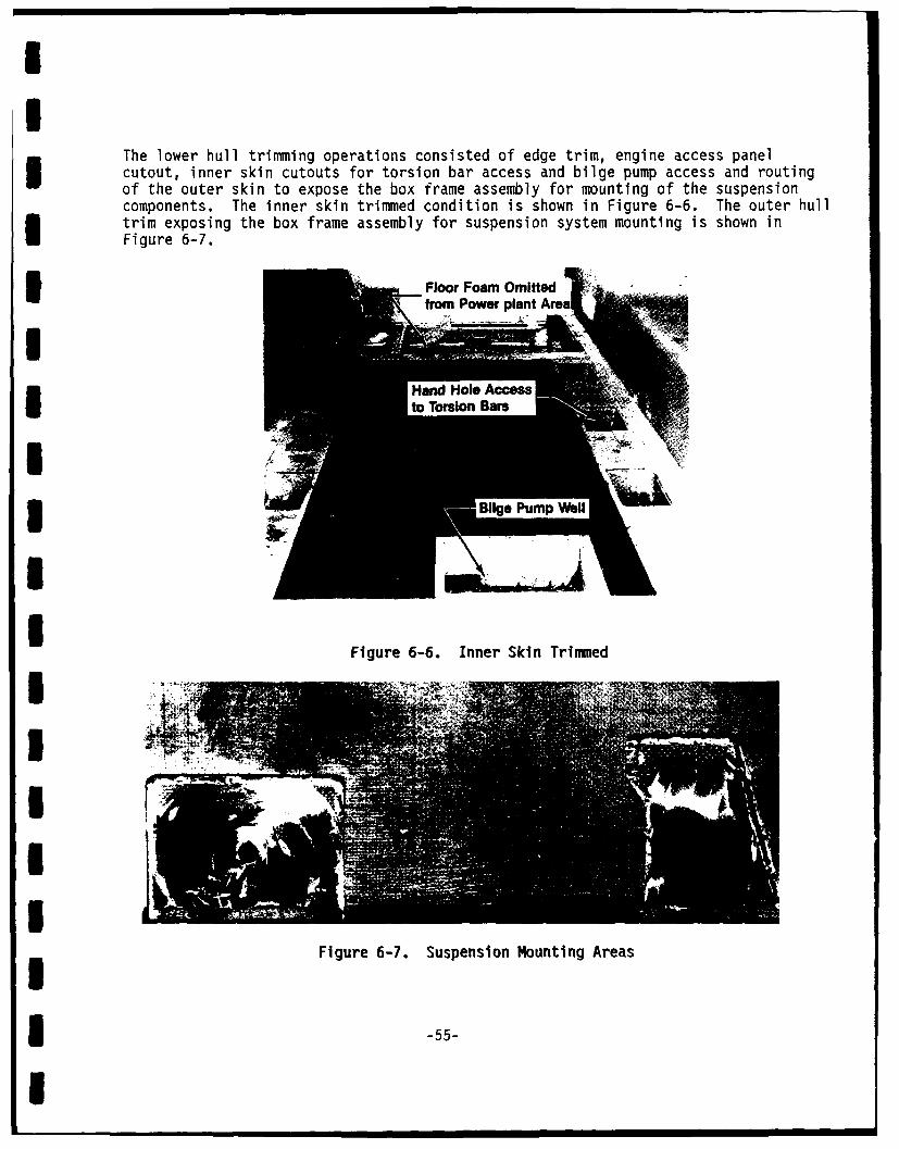
II
The lower hull trimming operations consisted of edge trim, engine access panelcutout, inner skin cutouts for torsion bar access and bilge pump access and routingof the outer skin to expose the box frame assembly for mounting of the suspensioncomponents. The inner skin trimmed condition is shown in Figure 6-6. The outer hulltrim exposing the box frame assembly for suspension system mounting is shown inFigure 6-7.
I Floor Foam Omitted • -from Power plant Area
Ito Torsion Bars
Figure 6-6. Inner Skin TrimmedI ;
III
Figure 6-7. Suspension Mounting Areas
* -55-
I
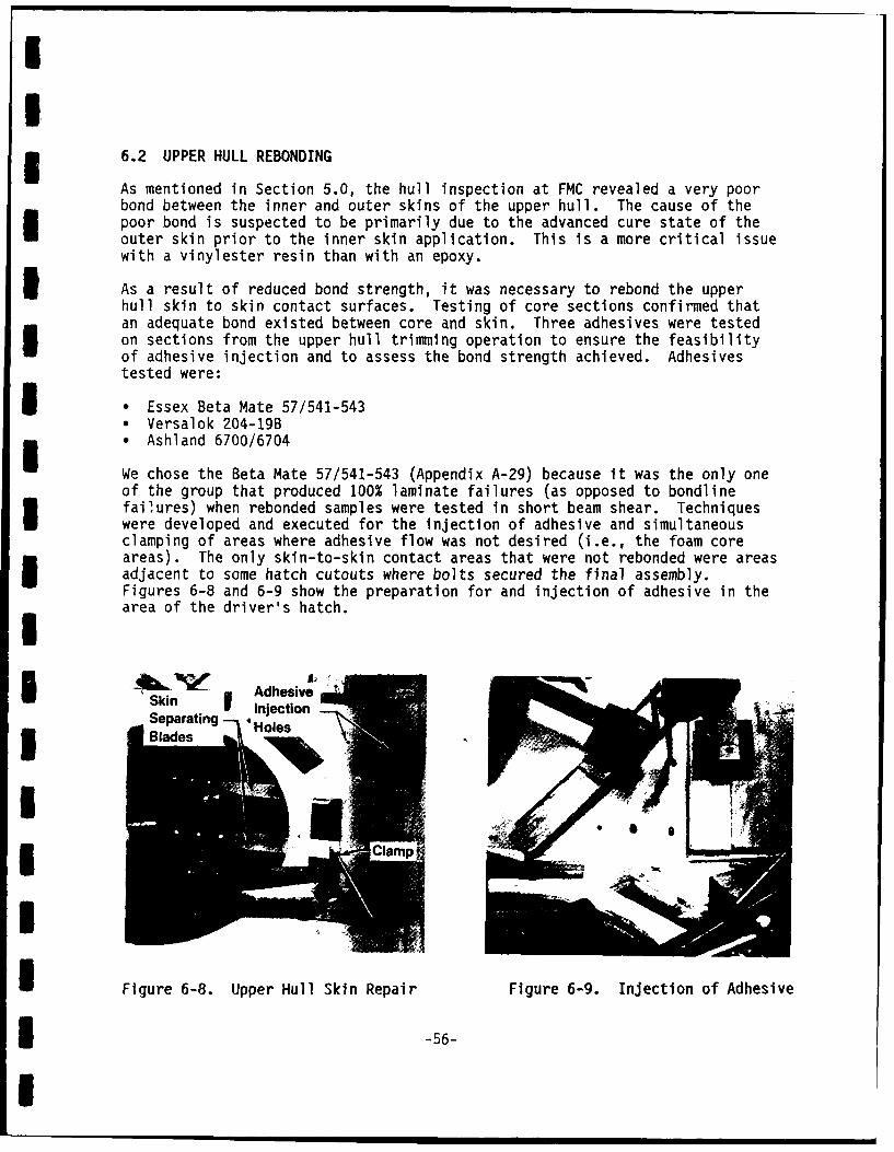
|II
I3 6.2 UPPER HULL REBONDING
As mentioned in Section 5.0, the hull inspection at FMC revealed a very poorbond between the inner and outer skins of the upper hull. The cause of thepoor bond is suspected to be primarily due to the advanced cure state of theouter skin prior to the inner skin application. This is a more critical issuewith a vinylester resin than with an epoxy.
3 As a result of reduced bond strength, it was necessary to rebond the upperhull skin to skin contact surfaces. Testing of core sections confirmed thatan adequate bond existed between core and skin. Three adhesives were testedon sections from the upper hull trimming operation to ensure the feasibilityof adhesive injection and to assess the bond strength achieved. Adhesivestested were:
I * Essex Beta Mate 57/541-543* Versalok 204-19B* Ashland 6700/6704
We chose the Beta Mate 57/541-543 (Appendix A-29) because it was the only oneof the group that produced 100% laminate failures (as opposed to bondlinefailures) when rebonded samples were tested in short beam shear. Techniqueswere developed and executed for the injection of adhesive and simultaneousclamping of areas where adhesive flow was not desired (i.e., the foam coreareas). The only skin-to-skin contact areas that were not rebonded were areasadjacent to some hatch cutouts where bolts secured the final assembly.Figures 6-8 and 6-9 show the preparation for and injection of adhesive in thearea of the driver's hatch.I
Ski AdhesiveInjection i
Separating - 4 oeIBlades Holes
I Figure 6-8. Upper Hull Skin Repair Figure 6-9. Injection of Adhesive
I -56-
I

II
6.3 HULL ASSEMBLY
The nose assembly (Figure 6-10) and the aft assembly were attached to theupper and lower hull sections. Temporary fasteners were used at the hulljoints to permit transportation to CEL without damage.
mm
II
5 Figure 6-10. Nose Assembly Attachment
A large trunion (Figure 6-11) was installed at CEL to facilitate wet layupwork and improve overall access to the hull. Doublers were applied, as shownin Figure 3-11, using Epon epoxy resin (Appendix A-3) with E-glass fabric at+450 to the vehicle axis. The doublers weighed 388 lb total and averaged3 65.2% glass at the time of application.
m -57-
I

I
II
3 Figure 6-11. Trunion-Mounted Hull
6.4 HOLE REPAIRS
During inspection of the upper hull, two 4-inch sample cores were taken fromeach sidewall. In repairing these holes, the skin surfaces were undercut from0-150 to compare ease of installation for the repair section and to permiteventual strength testing of the various shaped repair surfaces.
The right rear hole was undercut at 150 on each skin surface. The left rearhole was repaired as drilled (without any undercut) and the left front holewas undercut at 90 on each skin surface. The right front hole (seeFigure 6-4) was not undercut in the skins but featured a straight cone anglefrom a 4-inch diameter on the inner skin to a 5-inch diameter on the outer
-skin. All repairs used the same foam and fabric as that used on the originalupper hull layup. The resin used was Epon epoxy 815/V140. The straight coneangle was easiest to repair since no undercut accommodation was required. Wesuggest testing of these repaired holes to determine their relative strengthand overall adequacy.
* 6.5 ROOF BEAM
The roof beam was laid up in place using a foam core and a wet layup of epoxyresin (Appendix A-34) and E-glass woven fabric.
II -58-
I

6.6 TILE
Tile areas included both the upper and lower sidewalls and the left side ofthe upper glacis in front of the driver's position. With use of the rotatingtrunion, it was possible to cure each area in a horizontal position to avoidtile shifting. Individual tiles were provided with glass fiber spacers andloaded ten at a time into a woven "pocketed," E-glass fabric with the help ofan insertion tool. The area to be covered with tile was thoroughly wettedwith Epon 815-V140 epoxy. The dry cloth/tile assembly was then rolled intoplace. Added resin was applied to the outside ad b for e of the cloth; ableeder, peel ply and breather were added before the vacuum bag was applied.A room temperature cure was provided at 20-inch Hg vacuum. Figure 6-12 showspreparation for vacuum bagging of tiles on the upper glacis plate.
ImI
I
I
3 Figure 6-12. Tile Cure Preparations
6.7 MACHINING FOR SUSPENSION COMPONENTS
To ensure precision in hull preparation for mounting suspension system
components, we completed this work at the Ordnance Division Operationsfacility on numerically controlled equipment. Figure 6-13 shows the hullafter completion of suspension machining operations.
III -59-
m

I
3 Figure 6-13. Completed Composite Hull
6.8 INTEGRATION OF GOVERNMENT FURNISHED EQUIPMENT (GFE)
3 GFE included all necessary equipment to transform the composite hull into anoperating vehicle. The transformation from a composite hull (Figure 6-13) toan operating vehicle (Figure 6-14) took 2 months at our Plant 7 assembly site.
I
I
Figure 6-14. Completed Vehicle
I* -60-
I

II
7.0 VEHICLE TESTING
FMC conducted the following tests on the completed vehicle prior to delivery:
Ten-hour operational testsDesign verification tests (strain measurements)
* Flotation tests* Weight and CG tests• Safety tests
Vibration tests (accelerometer measurements)
* Interior noise testsl Hull rigidity tests
The first six of these tests are detailed in Appendix H-1, "Evaluation of theM113A1 with Composite Hull" (Technical Report 4189). The most significantresults are summarized below.
7.1 Ten-Hour Operational Tests
Test Engineering noted four problem areas during the ten-hour operationaltesting. Of these, three were not associated with using composite material inthe hull and were readily corrected with minor adjustments. One problemassociated with composite hull material was the failure of the parking braketo hold on during the 60% slope test. This problem was due to decreasedrigidity of composite material supporting the brake linkage. Once recognized,this problem was readily solved by welding-added stiffening members to linkagebrackets which served to redistribute and reduce the load resisted by thecomposite material.
3 7.2 Design Verification Tests
As shown in Figure 7-1, 14 strain gages were installed at key stress areasindicated by the FEA model. All were mounted on composite material except forgage 5 on the aft assembly and gage B on the engine bulkhead. Strainsrecorded, in accordance with the test plan, at twelve mph over a 6-inch high"double bump" obstacle were very low. Increasing the speed to 20 mph overthese bumps still produced a maximum of only 500 microstrain per channel.
Tests were continued to obtain more significant strain levels on the vehicle.A 9-inch high, metal "bump," designed for checkout of the Bradley FightingVehicle, was traversed at increasing speeds until a strain level of1,440 microstrain was measured. This occurred at 10 mph in the combat-loaded(3,000 lb ballast) condition (Figure 7-1). With the same loading, ameasurement of 888 microstrain was reached over the double 6-inch bumps at20 mph. Peak stresses calculated for these two runs were 5,487 psi and3,353 psi, respectively. The design limit for the area where these stressesoccurred is 17,100 psi (static) and 5,100 psi (fatigue). Although the safetyfactor of 2 was not maintained in these extreme tests, we established a highdegree of confidence in the design adequacy.
1 -61-
I

IOn Centedine
BetweenHatches
I __ Ge,_erS_ d
A Gage, Nar Side" Gage, Far Side, LIR Reverse* Acceleronieter Near Side
IFigure 7-1. Sensor Locations
I Two weight configurations were used to measure the flotation trim and stabil-
ity of the operational vehicle. In the lightly loaded configuration (driveri and full fuel), the static freeboard was measured at 16, 12, 22 and 25 inchesI starting at the left front corner and running clockwise (viewed from above).
In the simulated combat configuration (3,000 lb of added ballast) for the samelocations, the static freeboard measurements were 13.5, 10, 13.5 and3 16.5 inches.
Leakage was observed at the crew door seal and ramp seal during these tests.I In the lightly loaded condition, approximately 3 gal per minute were measuredI at the bilge pump discharge. After some work on better sealing, the combat-
loaded configuration tests produced a leakage rate of approximately 1.5 galI per minute.
* -62-
I
•~~~ ~ • C

II
7.3 Weight and Center of Gravity (CG) Tests
I Test procedures for determining weights and CG are detailed in Appendix H-i.
Results are discussed in Section 3.3.4.
1 7.4 Safety Tests
The vehicle was tested for presence of carbon monoxide in the crew compartmentwith the engine running for 1 hour at 1,000 rpm and the personnel heater oper-ating for 1/2 hour. No carbon monoxide was measured; however, the crew areadid show a slight positive pressure due to leakage from the pressurized enginecompartment. An analysis of safety issues is contained in Appendix H-2. Weidentified no adverse safety problem which prevented safe vehicle operation bya qualified driver.
7.5 Vibration Tests
An accelerometer was placed on the Inside, upper right sidewall approximately43 inches from the engine bulkhead and 1 inch from the roof curvaturemeasuring horizontal accelerations. Another accelerometer was placed on theoutside roof area between the weapon station and cargo hatch measuringvertical accelerations. The vehicle was then run over the 9-inch steel bumpat 8 mph. A graph of the frequency spectrum from the roof mountedaccelerometer is shown in Figure 7-2. This graph shows a strong 3-Hz responsewith decreasing amplitude responses from 30-160 Hz. The 3-Hz responsecorresponds to the "heave" natural frequency of the vehicle on its suspension-with-suspension components. Frequencies of about 24 Hz can be expected fromthe track interaction at 8 mph. Between 30-50 Hz, torsional motions and largeamplitude front-end motions from engine, transmission and drive units usuallypredominate.
I1
I,~
Figure 7-2. Vibration Frequencies
-63-
I

I
I
More complete acceleration data is presented in Appendix H-1 and a comparisonof data with FEA predictions is presented in Appendix H-5.
7.6 Interior Noise Tests
In accordance with MIL-STD-1474, interior noise levels were measured in thecrew compartment and in the driver's position at 15, 25 and 30 mph.Considerable reduction in noise level between 63 - 4,000 Hz was found comparedto the aluminum-hulled M113A1 vehicle. A comparison of noise levels in thecrew area at 25 mph is shown in Figure 7-3.I
- COOSITE HULl.. M113AI
125
120 - .
116 dBA
90 - ----- --- -
SIC U S 1 I IS 35S
115
mMl13 Interlor Noise Comprison with the Composite ill,
Crew Area * 25 Wit on a Pave Sarface.
I3 Figure 7-3. Nol se Comparl son
i On the average, the composite vehicle was 4.3 dBA quieter in the crewI compartment and 3.0 dBA quieter in the driver's position. A more detaileddiscussion of these data is contained in Appendix H-3.
3 7.7 Hull Rigidity Tests
Hull deflections were measured while applying a twisting force couple at them front of the vehicle. A hydraulic actuator applied the force under one of theI front corners with all other corners restrained. Dial indicators measured
vertical displacements of the vehicle's bottom corners, and vertical andhorizontal displacement of four areas at the intersection of the roof andsidewall. The test setup and a diagram of the indicator placement is shown in
Figure 7-4.m -64-
I
...... .. 10 mm l dBlA m l mm l

I4 3
X x56O0
• 0. 0 11 12 7 8
2 9 10
FRO NT
NOTE: THE LETTERS INDICATE THE FOLLOWING: BLOCK DIAGRAM OF DIAL GAUGE LOCATIONS
(G) DIAL GAUGES ITEST SET #1)
6(J) HYDRAULIC JACK NOTE: THE 'X' INDICATES GAUGES PLACkU UNDER
(S) SUPPORT THE HULL. THE '0' INDICATES GAUGESPLACED ABOVE OR BESIDE THE HULL.
Figure 7-4. Hull Rigidity Tests
Forces up to 16,000 lbs were applied to the left front of the vehicle result-ing in a rotation of approximately 1/40 of the vehicles front relative to therear as measured on the floor mounted indicators.
Table 7-1 shows the deflections recorded at each indicator for a typical tor-sion test. Appendix H-4 describes these tests In more detail and presents alltest results.
Table 7-1. Torsion Test DeflectionDEFLECTION (X Ir
3 INCHES) AT INDICATED Agu LocaIsOS
LOAD r - ** AE
(LU) 1 2 3 4 5 6 7 8 9 10 it tZ
Ii4,.500 -15 -108 -46 -25 T5 -75 11 -102 n 8 - 44 23
9.000 -36 237 -112 44 170 -175 231 -200 so -108 -10 log
10.000 46 -327 -186 53 262 -250 245 -275 189 -166 -119 273
S1.000 -132 -511 -28 63 368 -355 312 -381 374 -270 -132 371
2.006 -138 -554 -314 8O 425 -390 383 426 434 .430 -145 41213.000 -144 -591 -336 73 456 -412 504 -456 481 .548 -156 443
14.00 -151 -634 -386 77 494 -459 546 -491 530 -494 -170 410
15.000 -158 474 -MJ3 03 530 -47 591 -528 575 -530 -183 515
16.000 -163 -714 -421 08 565 -514 603 -564 61 .570 -1t 550
B.00 -163 -714 -421 SO s -514 603 -564 61 .510 -127 56615,000 -1S9 491 .406 66 454 -484 - -54 589 -561 -1n 538
14.000 -154 -03 -387 86 524 -394 680 -528 558 -537 -179 511
13.000 -149 -632 -365 84 495 -361 644 -501 524 -505 -10 471
12.000 -144 -.599 -341 82 464 -344 801 -472 485 -473 -161 451
11.0 0 -138 -565 -319 79 434 -316 575 -443 446 -443 -151 421
10.006 -56 -412 -253 72 358 -249 442 -267 291 -369 -151 350
9.00 -38 -302 -152 63 231 -234 300 -250 153 -2 -117 251
4.500 -17 -143 -60 41 163 -112 133 -130 68 -136 -64 120
0 0 -14 -2 It f3 -21 12 -13 i1 -7 -11 6
* REFER TO FIGURE 7-4 FOR CRUE LOCATIONS MINUS VALUES IN-ICATE EXTENSION.
* LOA* APPICATION POINT--65-
I

I
I7.8 Field Evaluations1 7.8.1 First Field Evaluation
After approximately 100 hours of field testing at the Amphibious Vehicle TestBranch, Camp Pendleton, CA, the vehicle was made available for contractorfield evaluation. Members of the FMC and OCF technical staff conducted thisevaluation on May 12-13, 1986. Methods used for evaluation included visualinspection, hammer tapping and ultrasonic thickness measuring. The primaryobjective was to determine the overall condition of the composite structureand to assess its ability to survive the planned, extended field testing.
I During the test period and evaluation, the vehicle was subjected to very hardusage. Indications of this included: broken mechanical components whichcaused loss of track on more than one occasion; failure of the number Iroadarm snubber bracket on the right side due to high impact loading; andfrequent deluging with solvents and fuel during the course of normal operationand maintenance. We concluded that the test program was indeed rigorous--as
m it should be.
Major conclusions from the initial field evaluation covering the first100 hours of Government testing were as follows:
* The vehicle underwent harsh treatment but appeared to be quite rugged.
3 , No major structural damage to the hull was found.
* The tiles appeared to be in good condition.
- The nonskid coating on the inside floor area appeared to be in excellentcondition.
m The urethane elastomer used to protect the sponson tiles from track abra-sion showed good adherence and low wear.
m An anomolous, 1/4-inch depth measurement was recorded during the ultrasonictesting in the driver's area.
The last conclusion warrants some discussion since the 1/4-inch depth measure-ments implies an unbonded area between the doubler and the structural skinwhich may have been caused by the test program. Since no ultrasonic scan wastaken of this section after the doubler was in place and prior to delivery onthe vehicle, we have no way of establishing whether the cause was a result ofthe unbonded condition inherent in the layup stage, the assembly process, highstress testing performed at FMC, or field test exposure. In any case, it isnot a major concern for future designs because that particular layuporientation used for this doubler would not be necessary or appropriate forfuture vehicles. Specifically, the 1/4-inch doubler consisted entirely offabric oriented at +450 to the vehicle axis to add torsional strength to the3 hull. The 3/8-inch-skin to which the doubler was applied, was laid up
* -66-
I

orthoganally to the vehicle axis. The abrupt difference in fabricdirectionality at the interface creates a high stress plane during vehicleloading, which would not exist if the +450 layers were interspersed with the0-900 layers evenly through each membe?. The interspersing of layers forms a"quasi-isotropic" system which would reduce the high stress condition at theinterface.
7.8.2 Second Field Evaluation
After 600 hours of field testing, FMC's technical staff made another trip toevaluate the overall condition of the vehicle. This evaluation was made onJuly 22, 1987. New conclusions drawn as a result of this inspection were asfollows:
m Long-term wear of exposed composite surfaces should not be a major problem.
0 Composite structures and components showed little or no degradation in thesame areas where metal components showed severe rust and/or corrosion.
U Long-term composite creep was not measurable at lifting lug whichcompressively loaded the laminate.
3 These conclusions are based on visual inspection of the floor wear, observa-tion of steel and aluminum bracketing inside the vehicle and torquemeasurements taken on lifting lug fasteners over an 18-month period.
Photographs of typical features after the 600-hour test are shown inFigures 7-5 through 7-13.I
I-IIi
I
Figure 7-5. Floor Surface Survived in Good Shape
-67-
I

III
I
Figure 7-6. Sponson Surface--Has Worn Off Paint But Shows No ExposedFibers
III
I Figure 7-7. Trinned Edge of Cargo Hatch Opening--No Visible Deterioration
* -68-
I

I4
Fiue78 ofBa-BodSosN erdto
IuOW " j5i
IT_ 1
5Figure 7- . Ro o B eam--Bosnd e-Shows RustDegrdtie on en'
-69

Fiur 7-0 Frn Lef L iftn Lu l Toqe hwNoMaual
III
Ip
IIII
Figure 7-10. Front Left Lifting Lug--Bolt Torques Show No Measurable
Compressive Creep in 18 Months
I j
I I
I Figure 7-11. Mounting Hardware on Roof--Shows Signs of Hard UseBut Remains Solidly Mounted
m -70-
I

II
I
IiI
Figure 7-12. Right Rear Tile Area--Aluminum Shows Heavy Gouging FromCaptive Rocks. Urethane Coating is Scraped Off ButNo Peeling Tendency is Evident
IIIII
Figure 7-13. Track Area--Excellent Abrasion Resistance FromUrethane Coating on Tiles
i -71-
I

8.0 ESTIMATED COSTS FOR DEVELOPMENT AND PRODUCTION
8.1 Development Costs
The development of a production-ready design requires extensive investigation,analysis and verification testing to define the most cost effective productionmethod. This effort must be coupled with the necessary design iterations toensure producibility of the final design with the selected manufacturingprocess. The manufacturing process development cost is estimated inTable 8-1. All costs referenced in Section 8.0 are in 1983 dollars.
Table 8-1. Estimated Cost for Manufacturing Processing Development
3 Materials Development $ 400,000Tooling Development 1,000,000Material Cut and Kit Development 400,000Material Transfer and Layup Development 600,000
Total $2,400,000
The cost of full-scale engineering development will add approximately$7,000,000 to the above development cost based on previous development programexperience. In addition, the cost of RAM-D and ILS is expected to beapproximately $2,000,000. Thus, a total development cost of $11.4 million is
* estimated.
8.2 Production Costs
A production cost of $47,000 per hull is estimated based on production of 1000vehicles over a 3-year period. Materials assumed are E-glass/polyester forthe upper hull and E-glass/epoxy for the lower hull. Composite materials will3 be applied in prepeg form. The construction is assumed to be monocoque.
Tables 8-2 through 8-4 provide a breakdown of the estimated unit costs.
3 Table 8-2. Estimated Unit Production Cost of Comosite Hulls
I Unit Cost Item Estimated Cost
Labor (260 man-hours @ $45/man-hour) $12,000Material 34,000Tooling ($1.2 M/1000) 1,000
Total $47,000Note: Cost rounded to nearest thousand.
3 -72-
I

I Il
I
m Table 8-3. Labor and Material Breakdown
LaborActivity (Man-hours) Materials
Fabricate Composites 104 $13,610Tile Application 16 9,559Aluminum Fabrication 22 2,200Assembly & Paint 37 3,200
I Subtotal (Labor) 179
Shop Support (15%) 27 -Quality Assurance (15%) 27 -Project Management (15%) 27 -Subtotal (Materials) 28,569Material Acquisition Cost (20%) 5,714
3 Total 260 $34,283
ITable 8-4. Basis Of Composite Materials EstimateI
Estimated Total CostMaterials Requirement (Yd) Cost/Yd Per Hull
E-glass/polyester 983 9.33 $9,170
m E-glass/epoxy 466 9.53 4,440
m Total $13,610
mIII -73-
I

mI
9.0 SUMMARY
FMC has designed and fabricated a composite hull for a tracked amphibiousvehicle. We have assembled the hull into an operating vehicle using GFEcomponents and tested the vehicle in accordance with contract requirements.Studies, test panels and drawings have been provided to complete thedeliverable items specified in the contract. Government testing of thevehicle was extended beyond the duration required in the original test plan --
the vehicle has survived this extended test period.
-IImUmmIIIIIi -74-
I

I
10.0 CONCLUSIONS
1 10.1 General
This program has demonstrated the feasibility of employing reinforced plasticsas the predominant structural material in the fabrication of an amphibiouscombat vehicle hull. Some potential advantages of this material are:
" Weight reduction -- Ballistic equivalency to aluminum can be obtained at areduced weight.
m Reduced life cycle costs -- Increased corrosion resistance and theelimination of stress corrosion and weld defects are expected.
* Material costs -- Pntential savings are expected in material costs asm production volumes are increased.
" Repairability -- Areas of repairability improvements over metal hullsinclude simpler logistics for field repairs and quicker battlefield repairsto watertight integrity.
" Reduced noise level -- Noise level was reduced throughout the composite3 hull vehicle.
10.2 Specific Conclusions
After design, fabrication, and testing of the composite hull, FMC concludedthe following:
m Sandwich and monocoque composite structures can be combined with aluminumstructural elements to form a strong and durable hull for armoredamphibious vehicles.
3 * Weight savings, increased ballistic protection and eventual life cycle costsavings can be expected from the use of composite hull structures in lieuof all metal hull structures.
I Rigidity as well as strength can be provided by composite structureswithout excessive volume penalties.
m ° Foam core construction is feasible structurally for combat vehicle hulls.
m Design and fabrication techniques are available to provide foam coresandwich construction for combat vehicles.
Integral layups of major metal structures within a composite hull increasesfabrication costs. It Is expected that maintenance and repair costs willalso be higher than independently fabricated metal and compositestructures.
I1 -75-
I

" Tolerances used were adequate to ensure assembly of the vehicle and couldIbe relaxed in future designs.
" It is difficult, but possible, to achieve uniform surface contact andbonding of a rigid core material to a precured skin surface in theproduction of a sandwich core hull structure.
* Unit costs per hull for a production run of 1000 vehicles are estimated tobe $47,000.
I111I|UI11I11
I-76-
1

II
11.0 RECOMMENDATIONS
FMC recommendations for use of composite materials on combat vehicles are asfollows:
* Reinforced-plastic materials should be considered in future combat vehicledesigns.
* * Designs for future demonstrators should not be restricted to thosedeveloped for metal hulls.
3 * Resin systems and fiber-reinforcing materials should be further developed.
* Various combinations of lamina for meeting ballistic structural and costI goals should be further investigated.
* Sandwich construction should be considered when uniform structural rigidityis required in addition to ballistic integrity and structural strength.
1 Depending upon mission requirements, a semi-monocoque or space frame designshould be considered for future combat vehicle hull structures.
3 * Integral layup of structural metal beams is not recommended due toincreased fabrication costs and increased maintenance and repair costs.
sandwich construction layup sequence should provide for a cocure of thefirst skin and core section (for rigid core materials) to avoid surfacefitup problems between skin and core.
ImIUII
I -77-
I