Embed Size (px)
Citation preview
i
DEVELOPMENT OF GENERAL PURPOSE GRAPHICS PROCESSING UNIT
WITH SHADING CAPABILITY
H’NG GAIK HI
A project report submitted in partial fulfilment of the
requirements for the award of the degree of
Master of Engineering (Electrical - Computer and Microelectronic System)
Faculty of Electrical Engineering
Universiti Teknologi Malaysia
JANUARY 2013
iii
ABSTRACT
In recent years, many GPU implementations had been done on FPGA.
GPGPU is a growing architecture for GPU due to its high programmability to
achieve high graphics and calculation throughput. In this work, a simplified version
of GPGPU has been implemented on FPGA. The GPGPU consists of minimum basic
building blocks required to be able to perform basic 3D transformations of triangle
primitive. The GPGPU consists of 2 fixed point units, register files (instructions,
temporary, vertices, constants) and raster unit. In order to obtain high throughput on
the GPGPU, calculation is approximated using look-up tables. Raster unit had been
optimized to take advantage of VGA display methodology by using incremental
scanline. Shader had been implemented with support enabled for flat and Gouraud
shading mode. The GPGPU is able to perform 12 different instructions and is able to
give a throughput of 2.5 MIPS. The final result of this work is a triangle primitive
programmed to rotate about the y-axis with either flat or Gouraud shading, displayed
onto a 640x480 digital display, with a maximum FPS of 111.1k on Gouraud shading.
iv
ABSTRAK
Pemnbangunan GPU dalam FPGA telah banyak diusahakan sejak
kebelakangan ini. GPGPU merupakan seni bina GPU yang sedang berkembang
kerana mempunyai keupayaan program yang tinggi dan mampu mencapai tahap
kadar grafik dan pengiraan yang tinggi. Dalam projek ini, GPGPU ringkas telah
diaplikasikan ke dalam FPGA. GPGPU ini mempunyai blok binaan asas yang
minima untuk melaksanakan transformasi 3D primitif segitiga. GPGPU ini
mempunyai 2 unit perpuluhan tetap, fail peringatan (arahan, sementara, verteks,
pemalar) dan unit raster. Untuk mencapai tahap pengeluaran yang tinggi, pengiraan
telah dilaksanakan secara penganggaraan menggunakan jadual. Unit raster juga telah
dioptimumkan untuk paparan VGA dengan menggunakan penambahan imbasan.
Shader juga telah dihasilkan untuk melaksanakan pengwarnaan rata dan Gouraud.
GPGPU ini berkemampuan untuk melaksanakan 12 arahan berbeza dengan kadar
pengeluaraan maksimum 2.5 MIPS. Hasil akhir projek ini ialah primitif segitiga
diprogramkan untuk berputar pada paksi-y dengan sama ada pengwarnaan rata atau
Gouraud. Segitiga ini akan disiarkan pada paparan digital 640x480 dengan kadar
FPS maksimum 111.1k menggunakan pengwarnaan Gouraud.
v
TABLE OF CONTENTS
CHAPTER TITLE PAGE
DECLARATION Ii
ABSTRACT Iii
ABSTRAK Iv
TABLE OF CONTENTS V
LIST OF TABLES vii
LIST OF FIGURES Ix
LIST OF ABBREVIATIONS Xi
LIST OF SYMBOLS xii
1 INTRODUCTION 1
1.1 Project Background 1
1.2 Problem Statement 2
1.3 Objectives 3
1.4 Scope 3
2 BRIEF THEORY AND LITERATURE REVIEW 4
2.1 Brief Theory on GPU Process 4
2.2 Previous Works on GPU Implementation on FPGA 5
2.2.1 An FPGA-based 3D Graphics System 5
2.2.2 Development of a Fixed Pipeline GPU on
FPGA
7
2.2.3 3D WireMesh Generator 8
vi
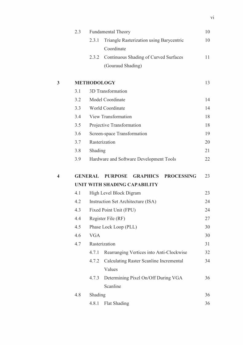
2.3 Fundamental Theory 10
2.3.1 Triangle Rasterization using Barycentric
Coordinate
10
2.3.2 Continuous Shading of Curved Surfaces
(Gouraud Shading)
11
3 METHODOLOGY 13
3.1 3D Transformation
3.2 Model Coordinate 14
3.3 World Coordinate 14
3.4 View Transformation 18
3.5 Projective Transformation 18
3.6 Screen-space Transformation 19
3.7 Rasterization 20
3.8 Shading 21
3.9 Hardware and Software Development Tools 22
4 GENERAL PURPOSE GRAPHICS PROCESSING
UNIT WITH SHADING CAPABILITY
23
4.1 High Level Block Digram 23
4.2 Instruction Set Architecture (ISA) 24
4.3 Fixed Point Unit (FPU) 24
4.4 Register File (RF) 27
4.5 Phase Lock Loop (PLL) 30
4.6 VGA 30
4.7 Rasterization 31
4.7.1 Rearranging Vertices into Anti-Clockwise 32
4.7.2 Calculating Raster Scanline Incremental
Values
34
4.7.3 Determining Pixel On/Off During VGA
Scanline
36
4.8 Shading 36
4.8.1 Flat Shading 36
vii
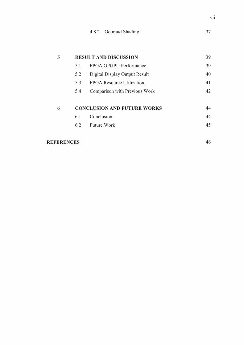
4.8.2 Gouraud Shading 37
5 RESULT AND DISCUSSION 39
5.1 FPGA GPGPU Performance 39
5.2 Digital Display Output Result 40
5.3 FPGA Resource Utilization 41
5.4 Comparison with Previous Work 42
6 CONCLUSION AND FUTURE WORKS 44
6.1 Conclusion 44
6.2 Future Work 45
REFERENCES 46
viii
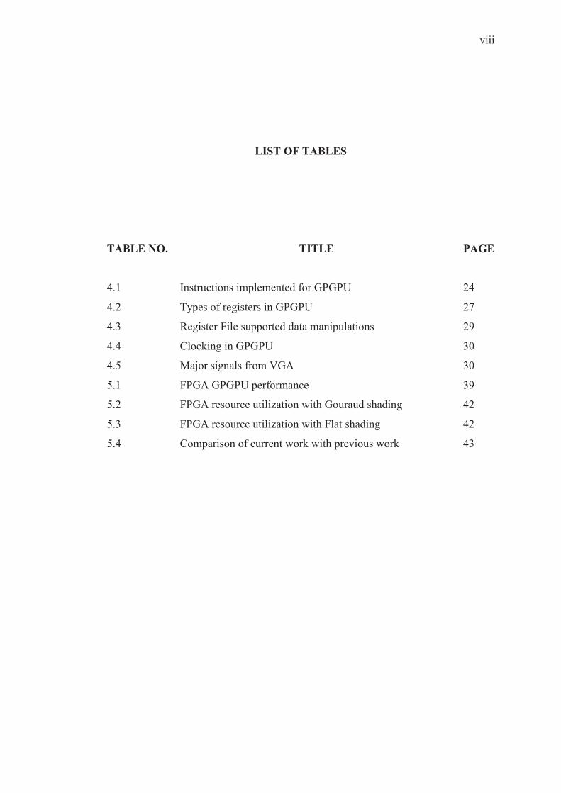
LIST OF TABLES
TABLE NO. TITLE PAGE
4.1 Instructions implemented for GPGPU 24
4.2 Types of registers in GPGPU 27
4.3 Register File supported data manipulations 29
4.4 Clocking in GPGPU 30
4.5 Major signals from VGA 30
5.1 FPGA GPGPU performance 39
5.2 FPGA resource utilization with Gouraud shading 42
5.3 FPGA resource utilization with Flat shading 42
5.4 Comparison of current work with previous work 43
ix
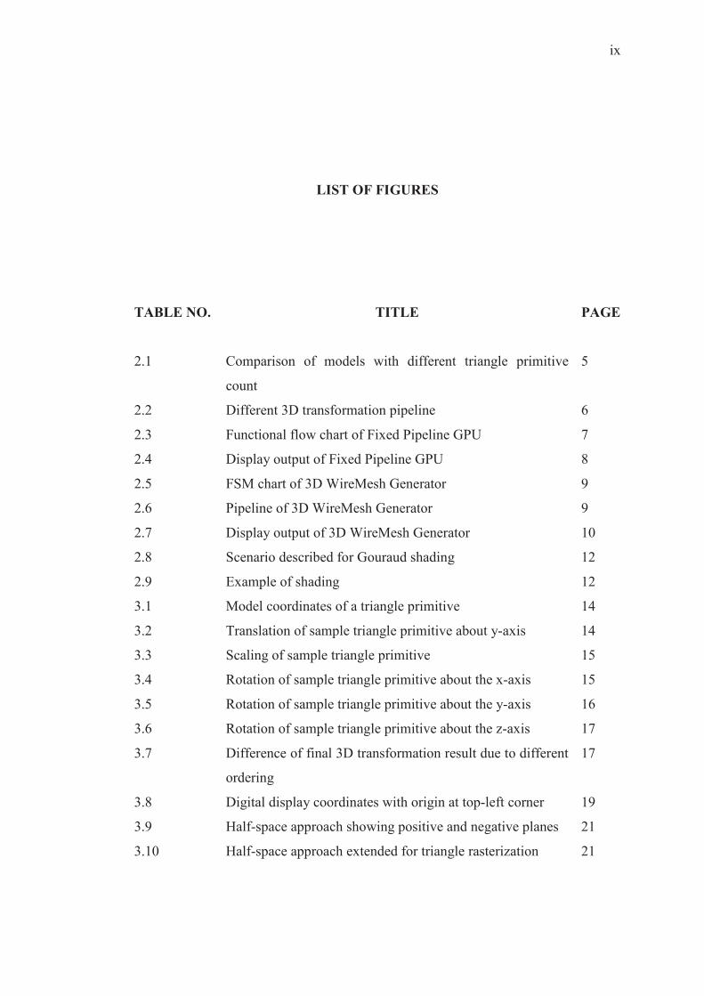
LIST OF FIGURES
TABLE NO. TITLE PAGE
2.1 Comparison of models with different triangle primitive
count
5
2.2 Different 3D transformation pipeline 6
2.3 Functional flow chart of Fixed Pipeline GPU 7
2.4 Display output of Fixed Pipeline GPU 8
2.5 FSM chart of 3D WireMesh Generator 9
2.6 Pipeline of 3D WireMesh Generator 9
2.7 Display output of 3D WireMesh Generator 10
2.8 Scenario described for Gouraud shading 12
2.9 Example of shading 12
3.1 Model coordinates of a triangle primitive 14
3.2 Translation of sample triangle primitive about y-axis 14
3.3 Scaling of sample triangle primitive 15
3.4 Rotation of sample triangle primitive about the x-axis 15
3.5 Rotation of sample triangle primitive about the y-axis 16
3.6 Rotation of sample triangle primitive about the z-axis 17
3.7 Difference of final 3D transformation result due to different
ordering
17
3.8 Digital display coordinates with origin at top-left corner 19
3.9 Half-space approach showing positive and negative planes 21
3.10 Half-space approach extended for triangle rasterization 21
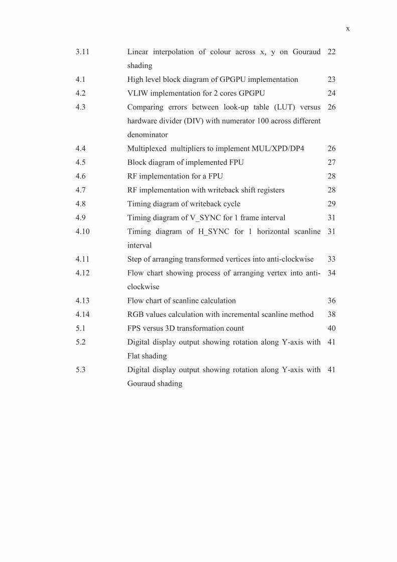
x
3.11 Linear interpolation of colour across x, y on Gouraud
shading
22
4.1 High level block diagram of GPGPU implementation 23
4.2 VLIW implementation for 2 cores GPGPU 24
4.3 Comparing errors between look-up table (LUT) versus
hardware divider (DIV) with numerator 100 across different
denominator
26
4.4 Multiplexed multipliers to implement MUL/XPD/DP4 26
4.5 Block diagram of implemented FPU 27
4.6 RF implementation for a FPU 28
4.7 RF implementation with writeback shift registers 28
4.8 Timing diagram of writeback cycle 29
4.9 Timing diagram of V_SYNC for 1 frame interval 31
4.10 Timing diagram of H_SYNC for 1 horizontal scanline
interval
31
4.11 Step of arranging transformed vertices into anti-clockwise 33
4.12 Flow chart showing process of arranging vertex into anti-
clockwise
34
4.13 Flow chart of scanline calculation 36
4.14 RGB values calculation with incremental scanline method 38
5.1 FPS versus 3D transformation count 40
5.2 Digital display output showing rotation along Y-axis with
Flat shading
41
5.3 Digital display output showing rotation along Y-axis with
Gouraud shading
41
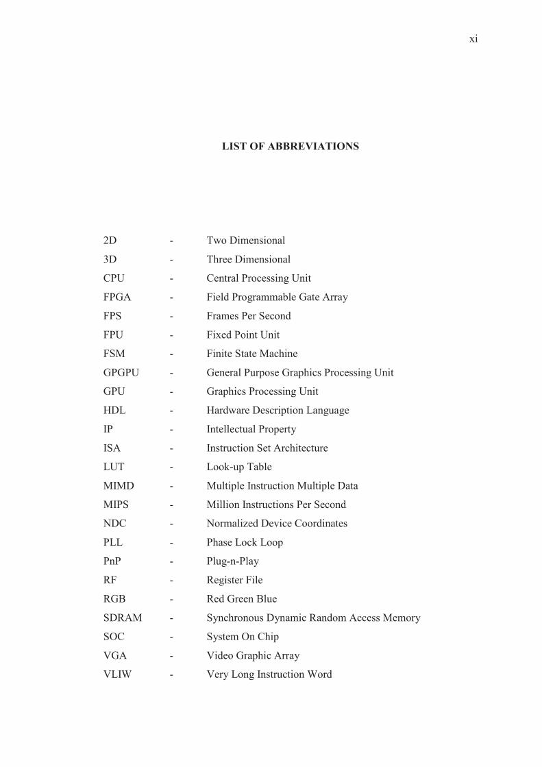
xi
LIST OF ABBREVIATIONS
2D - Two Dimensional
3D - Three Dimensional
CPU - Central Processing Unit
FPGA - Field Programmable Gate Array
FPS - Frames Per Second
FPU - Fixed Point Unit
FSM - Finite State Machine
GPGPU - General Purpose Graphics Processing Unit
GPU - Graphics Processing Unit
HDL - Hardware Description Language
IP - Intellectual Property
ISA - Instruction Set Architecture
LUT - Look-up Table
MIMD - Multiple Instruction Multiple Data
MIPS - Million Instructions Per Second
NDC - Normalized Device Coordinates
PLL - Phase Lock Loop
PnP - Plug-n-Play
RF - Register File
RGB - Red Green Blue
SDRAM - Synchronous Dynamic Random Access Memory
SOC - System On Chip
VGA - Video Graphic Array
VLIW - Very Long Instruction Word
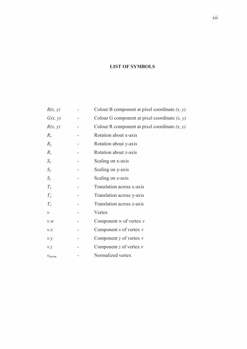
xii
LIST OF SYMBOLS
B(x, y) - Colour B component at pixel coordinate (x, y)
G(x, y) - Colour G component at pixel coordinate (x, y)
R(x, y) - Colour R component at pixel coordinate (x, y)
Rx - Rotation about x-axis
Ry - Rotation about y-axis
Rz - Rotation about z-axis
Sx - Scaling on x-axis
Sy - Scaling on y-axis
Sz - Scaling on z-axis
Tx - Translation across x-axis
Ty - Translation across y-axis
Tz - Translation across z-axis
v - Vertex
v.w - Component w of vertex v
v.x - Component x of vertex v
v.y - Component y of vertex v
v.z - Component z of vertex v
vnorm - Normalized vertex
��
�
CHAPTER 1
INTRODUCTION
1.1 Project Background
Graphics processing is an essential process of manipulating and altering
memory to accelerate the building of image to be displayed. This process is needed
in embedded systems, mobile phones, computers and game consoles.
However, in order to allow main processing unit to perform other processes
rather than having graphics processing utilizing all the resources, a discrete graphics
processing unit (GPU) is needed. The main processing unit will identify graphic
processing specific instructions and offload into the GPU to be processed. GPUs are
far more efficient in parallel processing due to the highly parallel and pipelined
structure which allows large blocks of data to be processed concurrently. Other than
that, modern GPUs also have their own dedicated memory instead of shared memory
with main processing unit. This feature allows GPUs to directly perform
manipulation and altering into the dedicated memory without being bottlenecked by
bandwidth and traffic congestion between GPU and main memory.
General Purpose Graphics Processing Unit (GPGPU) is a new GPU
architecture whereby it not only is capable to compute graphical related
��
�
computations, but also is programmable to compute computations traditionally
handled by CPU. GPGPU takes advantage of the large amount of processing cores
available to achieve high parallelism in computation.
Field Programmable Gate Array (FPGA) is an integrated circuit which can be
configured by end user to implement functions defined by the designer. FPGAs are
gaining popularity in design implementation due to their increasing logic density
which had reduced the cost per logic. FPGAs can be configured to meet custom
requirement or functions and as well as performing tasks that can be done in parallel
and pipelined whereby hardware outperforms software. Other than that, with
existence of internet community designing and publishing IP cores, such as
OpenCores, had allowed many custom designs to be made by Plug-and-Play (PnP) of
multiple IP cores into single SOC using FPGAs.
In this project, we will utilize the advantage of hardware parallelism to design
a simplified version of GPGPU on FPGA with shader capability.
1.2 Problem Statement
3D transformation on software is slow and resource demanding. Hardware
implementation of 3D transformation increases the performance by utilizing high
parallelism to perform building of image frames. GPGPU which processes 3D
transformation will be implemented on FPGA, allowing the reuse of this GPGPU IP
core on other SOC design.
��
�
1.3 Objectives
The objectives of this project are as below:
i. To implement GPGPU core on Altera DE2 FPGA board.
ii. To enhance previous simple GPU design from fixed pipeline GPU into
GPGPU architecture.
iii. To enhance previous simple GPU of wireframe output with Flat and Gouraud
shading.
iv. To render a sample triangle primitive onto a digital display.
v. To compare the performance of this design with previous works.
1.4 Scope
This project requires in-depth understanding on GPGPU architecture and 3D
transformation pipeline and its processes. Knowledge on various shader models are
needed in order to implement the shader capabilities into the GPGPU. Other than that,
in order to program an FPGA, knowledge on Hardware Descriptive Language (HDL)
is needed. Due to the vast scope of the topic, this project will be limited to:
i. Design of GPGPU, raster, and shader.
ii. Implementation of GPGPU with minimal instructions needed to perform
basic 3D transformation.
iii. Support of triangle primitive.
iv. Shader will implement both flat and Gouraud shading.
v. Implement designs into FPGA using Verilog HDL.
vi. Render a shaded triangle primitive onto a display monitor and measure the
frame rate in frames per second (FPS).
��
�
CHAPTER 2
BRIEF THEORY AND LITERATURE REVIEW
2.1 Brief Theory on GPU Process
In 3D graphics processing, the virtual “world” is made up of 3 axes of
coordinates (x, y, z), just like the world we are living in. However, in order to display
this 3D world onto a 2D display of (x, y) coordinates, 3D transformation is needed to
transform 3D world into 2D image frame to be displayed on the monitor.
In 3D graphics processing, triangle primitive is one of the basic building
blocks of an object where a single object can be made up of from few up to
thousands of triangles, depending on the detail.
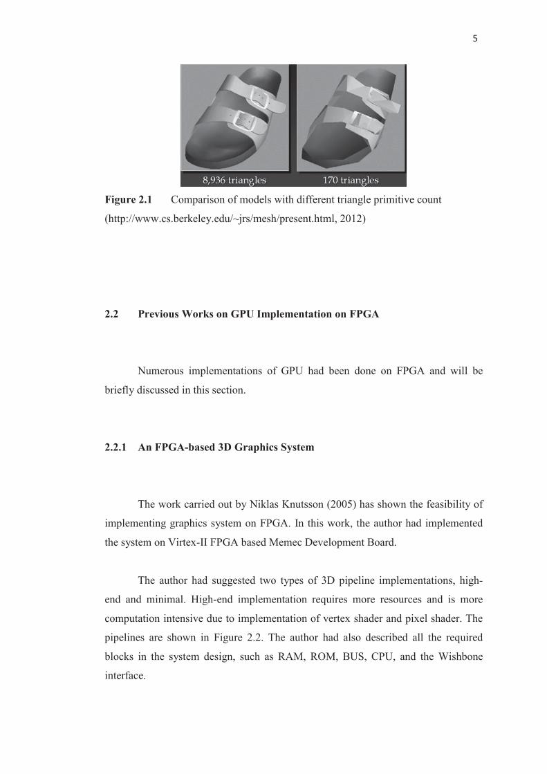
Each triangle consists of 3 coordinates in the 3D world. These 3 coordinates
are connected to form a triangle. Models can be created using few or many triangles;
with fewer triangles, the model will look bulky; with more triangles, the model will
look smoother, as shown in Figure 2.1.
��
�
Figure 2.1 Comparison of models with different triangle primitive count
(http://www.cs.berkeley.edu/~jrs/mesh/present.html, 2012)
2.2 Previous Works on GPU Implementation on FPGA
Numerous implementations of GPU had been done on FPGA and will be
briefly discussed in this section.
2.2.1 An FPGA-based 3D Graphics System
The work carried out by Niklas Knutsson (2005) has shown the feasibility of
implementing graphics system on FPGA. In this work, the author had implemented
the system on Virtex-II FPGA based Memec Development Board.
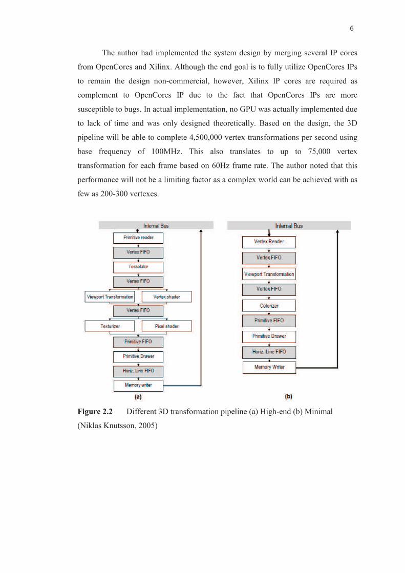
The author had suggested two types of 3D pipeline implementations, high-
end and minimal. High-end implementation requires more resources and is more
computation intensive due to implementation of vertex shader and pixel shader. The
pipelines are shown in Figure 2.2. The author had also described all the required
blocks in the system design, such as RAM, ROM, BUS, CPU, and the Wishbone
interface.
��
�
The author had implemented the system design by merging several IP cores
from OpenCores and Xilinx. Although the end goal is to fully utilize OpenCores IPs
to remain the design non-commercial, however, Xilinx IP cores are required as
complement to OpenCores IP due to the fact that OpenCores IPs are more
susceptible to bugs. In actual implementation, no GPU was actually implemented due
to lack of time and was only designed theoretically. Based on the design, the 3D
pipeline will be able to complete 4,500,000 vertex transformations per second using
base frequency of 100MHz. This also translates to up to 75,000 vertex
transformation for each frame based on 60Hz frame rate. The author noted that this
performance will not be a limiting factor as a complex world can be achieved with as
few as 200-300 vertexes.
Figure 2.2 Different 3D transformation pipeline (a) High-end (b) Minimal
(Niklas Knutsson, 2005)
��
�
2.2.2 Development of a Fixed Pipeline GPU on FPGA
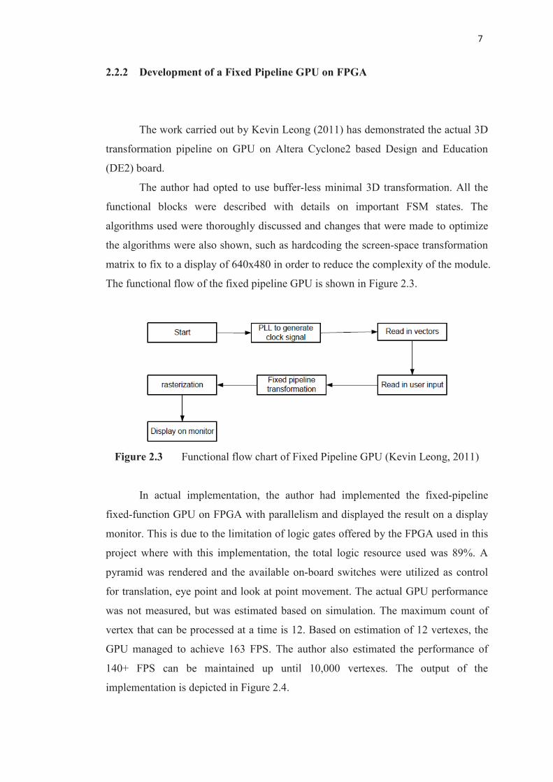
The work carried out by Kevin Leong (2011) has demonstrated the actual 3D
transformation pipeline on GPU on Altera Cyclone2 based Design and Education
(DE2) board.
The author had opted to use buffer-less minimal 3D transformation. All the
functional blocks were described with details on important FSM states. The
algorithms used were thoroughly discussed and changes that were made to optimize
the algorithms were also shown, such as hardcoding the screen-space transformation
matrix to fix to a display of 640x480 in order to reduce the complexity of the module.
The functional flow of the fixed pipeline GPU is shown in Figure 2.3.
Figure 2.3 Functional flow chart of Fixed Pipeline GPU (Kevin Leong, 2011)
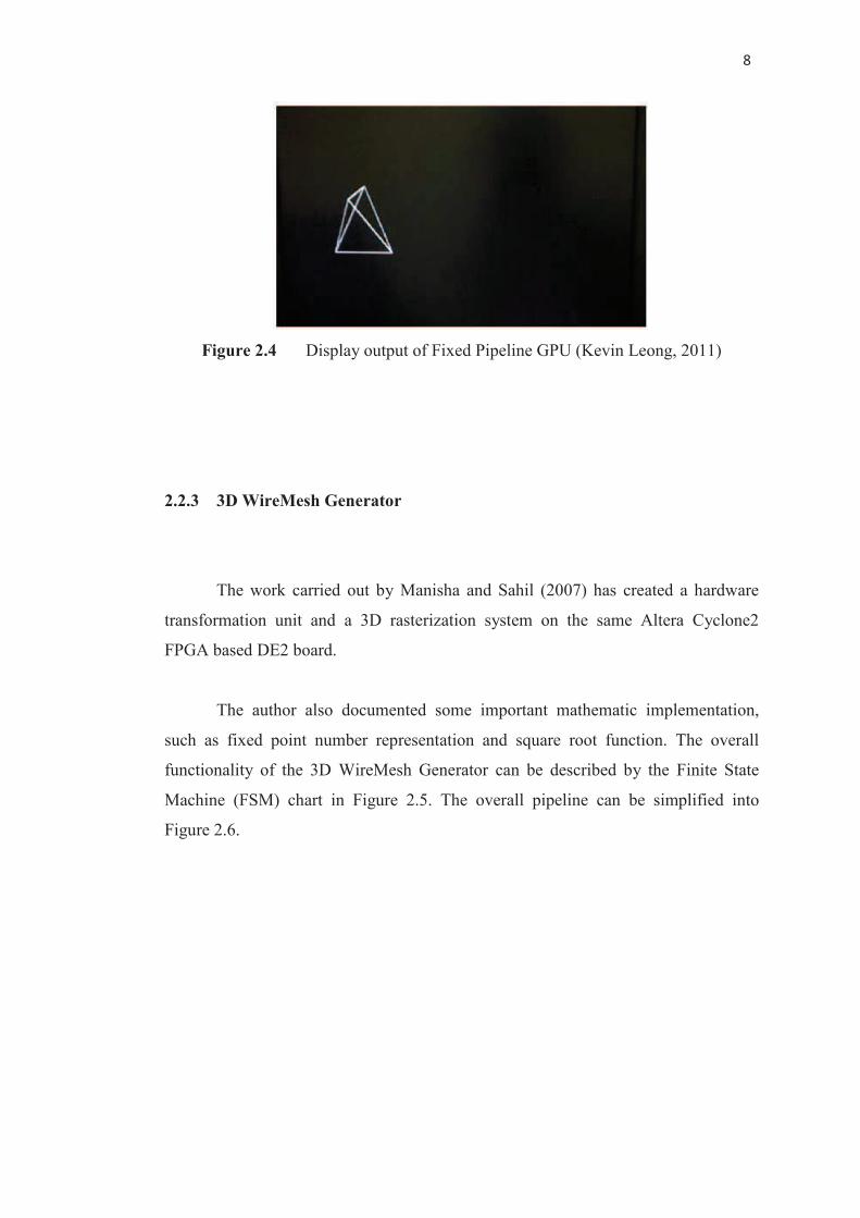
In actual implementation, the author had implemented the fixed-pipeline
fixed-function GPU on FPGA with parallelism and displayed the result on a display
monitor. This is due to the limitation of logic gates offered by the FPGA used in this
project where with this implementation, the total logic resource used was 89%. A
pyramid was rendered and the available on-board switches were utilized as control
for translation, eye point and look at point movement. The actual GPU performance
was not measured, but was estimated based on simulation. The maximum count of
vertex that can be processed at a time is 12. Based on estimation of 12 vertexes, the
GPU managed to achieve 163 FPS. The author also estimated the performance of
140+ FPS can be maintained up until 10,000 vertexes. The output of the
implementation is depicted in Figure 2.4.
�
�
Figure 2.4 Display output of Fixed Pipeline GPU (Kevin Leong, 2011)
2.2.3 3D WireMesh Generator
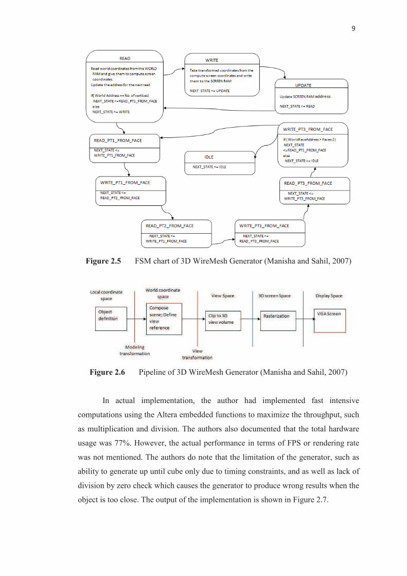
The work carried out by Manisha and Sahil (2007) has created a hardware
transformation unit and a 3D rasterization system on the same Altera Cyclone2
FPGA based DE2 board.
The author also documented some important mathematic implementation,
such as fixed point number representation and square root function. The overall
functionality of the 3D WireMesh Generator can be described by the Finite State
Machine (FSM) chart in Figure 2.5. The overall pipeline can be simplified into
Figure 2.6.
�
�
Figure 2.5 FSM chart of 3D WireMesh Generator (Manisha and Sahil, 2007)
Figure 2.6 Pipeline of 3D WireMesh Generator (Manisha and Sahil, 2007)
In actual implementation, the author had implemented fast intensive
computations using the Altera embedded functions to maximize the throughput, such
as multiplication and division. The authors also documented that the total hardware
usage was 77%. However, the actual performance in terms of FPS or rendering rate
was not mentioned. The authors do note that the limitation of the generator, such as
ability to generate up until cube only due to timing constraints, and as well as lack of
division by zero check which causes the generator to produce wrong results when the
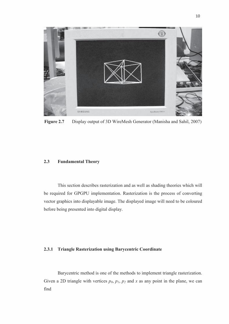
object is too close. The output of the implementation is shown in Figure 2.7.
���
�
Figure 2.7 Display output of 3D WireMesh Generator (Manisha and Sahil, 2007)
2.3 Fundamental Theory
This section describes rasterization and as well as shading theories which will
be required for GPGPU implementation. Rasterization is the process of converting
vector graphics into displayable image. The displayed image will need to be coloured
before being presented into digital display.
2.3.1 Triangle Rasterization using Barycentric Coordinate
Barycentric method is one of the methods to implement triangle rasterization.
Given a 2D triangle with vertices p0, p1, p2 and x as any point in the plane, we can
find
���
�� � ��� � ��� � ��� ����� � � � � � (2.1)
To draw a triangle with vertices pi = (xi, yi), i = 0, 1, 2, the vertices is then
normalized into Normalized Device Coordinates (NDC) with range of [-1, 1] x [-1,
1]. Then the NDC will be converted into Barycentric coordinates fab(x, y),
������ �� � ��� � ���� ���� � ���� ����� ������ ����� � � �� �� � (2.2a)
� � ������ ��������� ��� (2.2b)
� � ������ ��������� ��� (2.2c)
� ������ ��������� ��� (2.2d)
With values �, �, �, we will check whether all �, �, � lie within [0, 1], if not,
the current pixel is outside the triangle; else, the pixel needs to be drawn.
2.3.2 Continuous Shading of Curved Surfaces (Gouraud Shading)
The work carried out by Henri Gouraud (1971) has created an algorithm to
shade a model more realistically compared to uniform/flat shading.
Compared to uniform/flat shading, where shading value for a polygon is
determined by calculating the normal for that particular polygon as a vector
perpendicular to the plane of the polygon, Gouraud shading calculates the shading
value of each point inside the polygon (pixel).
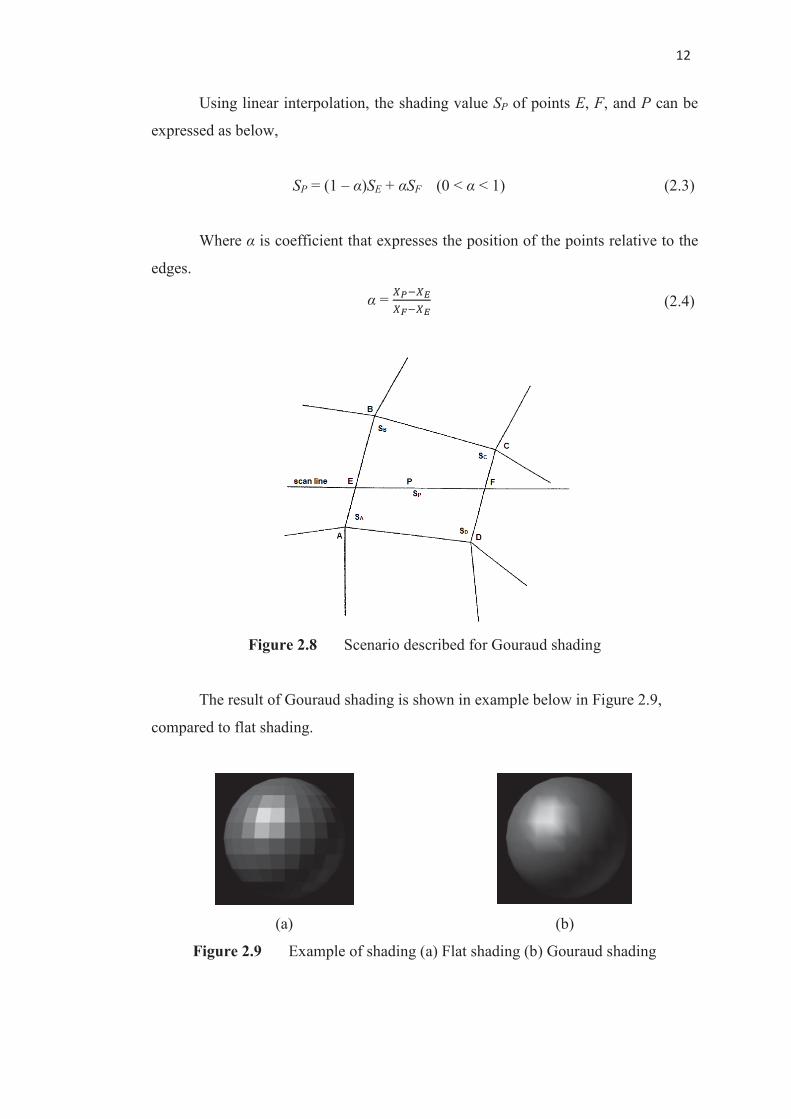
Given the scenario (Figure 2.8) where two edges for a polygon, AB and CD,
and scan line EF which cross over the polygon, and point P as point on the scan line,
the normal for the points A, B, C, and D can be computed.
���
�
Using linear interpolation, the shading value SP of points E, F, and P can be
expressed as below,
SP = (1 – �)SE + �SF (0 < � < 1) (2.3)
Where � is coefficient that expresses the position of the points relative to the
edges.
� = �� �!�" �! (2.4)
Figure 2.8 Scenario described for Gouraud shading
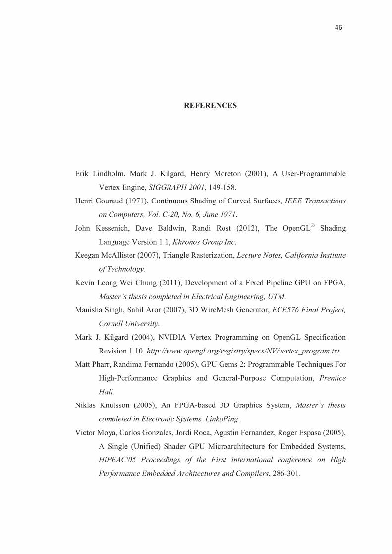
The result of Gouraud shading is shown in example below in Figure 2.9,
compared to flat shading.
(a)� (b)�
Figure 2.9 Example of shading (a) Flat shading (b) Gouraud shading
���
�
REFERENCES
Erik Lindholm, Mark J. Kilgard, Henry Moreton (2001), A User-Programmable
Vertex Engine, SIGGRAPH 2001, 149-158.
Henri Gouraud (1971), Continuous Shading of Curved Surfaces, IEEE Transactions
on Computers, Vol. C-20, No. 6, June 1971.
John Kessenich, Dave Baldwin, Randi Rost (2012), The OpenGL®
Shading
Language Version 1.1, Khronos Group Inc.
Keegan McAllister (2007), Triangle Rasterization, Lecture Notes, California Institute
of Technology.
Kevin Leong Wei Chung (2011), Development of a Fixed Pipeline GPU on FPGA,
Master’s thesis completed in Electrical Engineering, UTM.
Manisha Singh, Sahil Aror (2007), 3D WireMesh Generator, ECE576 Final Project,
Cornell University.
Mark J. Kilgard (2004), NVIDIA Vertex Programming on OpenGL Specification
Revision 1.10, http://www.opengl.org/registry/specs/NV/vertex_program.txt
Matt Pharr, Randima Fernando (2005), GPU Gems 2: Programmable Techniques For
High-Performance Graphics and General-Purpose Computation, Prentice
Hall.
Niklas Knutsson (2005), An FPGA-based 3D Graphics System, Master’s thesis
completed in Electronic Systems, LinkoPing.
Victor Moya, Carlos Gonzales, Jordi Roca, Agustin Fernandez, Roger Espasa (2005),
A Single (Unified) Shader GPU Microarchitecture for Embedded Systems,
HiPEAC'05 Proceedings of the First international conference on High
Performance Embedded Architectures and Compilers, 286-301.