Embed Size (px)
Citation preview
I
R
1
2
3
4
5
6
7
8
9
10
11
12
13
T
14
15
166-46
PHONE: 516.328.3300 • FAX: 516.326.8827 • WWW.SDP-SI.COM
0 1Inch
Disk couplings are designed to operate under heavy loads while providing a certain degree of freedom for misalignment. The following series provide exceptional performance in this regard. Please use the selection chart to decide which series best fits your application.
Zero Backlash: All series of couplings listed below have zero backlash, ensuring no lost motion.
High Torsional Stiffness: A coupling with higher torsional stiffness receives less torsional displacement from the same load, which creates less wind up and allows quicker startup time for the connected shaft.
High Torque: A higher maximum allowable torque is desirable for heavier load applications.
Allowable Misalignment: A coupling with a higher degree of allowable misalignment will still allow power transmission in applications where axial shaft alignment is less precise.
DISK COUPLING GUIDE
MTD MDS MDD
MHS MHW
SERIESSpecial
Characteristics MDS MHWMHS
Zero Backlash
High Torsional Stiffness
High Torque
Allowable Misalignment
MDD
pg. 6-48 pg. 6-49 pg. 6-50 pg. 6-51CatalogPage pg. 6-47
MTD
E
V
E
E
V
V
E
V
V
V
E
V
V
E
E
V
E: Excellent V: Very good
I
R
1
2
3
4
5
6
7
8
9
10
11
12
13
T
14
15
166-47
PHONE: 516.328.3300 • FAX: 516.326.8827 • WWW.SDP-SI.COM
0 1Inch
DOUBLE DISK FLEXIBLE COUPLINGS
ZERO BACKLASHLOW TORSIONAL STIFFNESSEXCELLENT RESPONSELIGHTWEIGHT
MATERIAL: Pins & Disks - Stainless SteelHubs & Spacer - Anodized Aluminum
SPECIFICATION:Bore Tolerance: .2500 & .3750 +.0009/-.0000
.5000 +.0011/-.0000
Other bore diameter combinations and bore sizes not exceeding the maximum listed below are available on special order.
Catalog Number ∆
Coupling Series(Ref.)
INCH COMPONENT
∆ To be discontinued when present stock is depleted.* Based on Max. Bore.
BBoreO.D. L
LengthSet
ScrewMax.Bore
Moment of Inertia*
oz. in.2
Static Torsional Stiffnesslbf in. / deg
Max.rpm
RatedTorquelbf in.
Weight *oz.
Max.LateralOffset
Max.Axial
Motion
Max.AngularOffset
1° 1.5°
2°
± .016± .020± .024
310002500019000
4.43 8.8517.70
S50MTD-078P...S50MTD-098P...S50MTD-126P...
.74 .951.52
.004
.006
.066
.142
.366
18.5432.4435.53
S50MTD-078P25P25S50MTD-078P37P37S50MTD-098P25P25S50MTD-098P37P37S50MTD-126P37P37S50MTD-126P50P50
.787
.984
1.260
.2500
.3750
.2500
.3750
.5000
1.075
1.079
1.083
#4-40
#6-32
.3150
.4724
.5512
ØB
L
O.D.
.295 .295SET SCREW2 AT EACH END
Rev: 9.11.13 JC
I
R
1
2
3
4
5
6
7
8
9
10
11
12
13
T
14
15
166-48
PHONE: 516.328.3300 • FAX: 516.326.8827 • WWW.SDP-SI.COM
0 1Inch
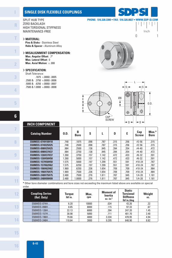
6.20 8.85 22.13 30.98 79.66110.64
1000080006000500040003000
.034 .115 .394 .7113.3349.295
43.26 97.33247.20401.70478.95648.90
.32 .671.452.404.948.82
Coupling Series(Ref. Only)
Torquelbf in.
Max.rpm
Moment ofInertiaoz. in.2
StaticTorsionalStiffnesslbf in./deg
Weightoz.
S50MDS-074H…S50MDS-098H…S50MDS-126H…S50MDS-157H…S50MDS-196H…S50MDS-248H…
.748
.748
.984
.9841.2601.2601.5751.5751.9691.9692.4802.480
.1875 .2500 .2500 .3750 .3750 .5000 .5000 .6250 .6250 .7500 .75001.0000
.098
.098
.138
.138
.157
.157
.197
.197
.236
.236
.276
.276
.787
.787
.945
.9451.1421.1421.2991.2991.6541.6541.8111.811
.315
.315
.394
.394
.472
.472
.551
.551
.709
.709
.787
.787
.256
.256
.354
.354
.433
.433
.591
.591
.709
.709
.945
.945
#2-56#2-56#4-40#4-40#6-32#6-32#10-24#10-24#10-24#10-241/4-201/4-20
.315
.315
.472
.472
.591
.591
.787
.787
.984
.9841.1811.181
INCH COMPONENT
S50MDS-074H18H18S50MDS-074H25H25S50MDS-098H25H25S50MDS-098H37H37S50MDS-126H37H37S50MDS-126H50H50S50MDS-157H50H50S50MDS-157H62H62S50MDS-196H62H62S50MDS-196H75H75S50MDS-248H75H75S50MDS-248H99H99
BBoreO.D. S L D E Max.*
BoreCap
ScrewCatalog Number
* Other bore diameter combinations and bore sizes not exceeding the maximum listed above are available on special order.
CAP SCREW
E
E
L
S S
ØB
O.D.
D D
SPLIT HUB TYPEZERO BACKLASHHIGH TORSIONAL STIFFNESSMAINTENANCE-FREE
MATERIAL: Pins & Disks - Stainless Steel Hubs & Spacer - Aluminum Alloy
MISALIGNMENT COMPENSATION: Max. Angular Offset: .7° Max. Lateral Offset: 0 Max. Axial Motion: ± .008
SPECIFICATION: Shaft Tolerance: .1875 +.0000/-.0005 .2500 & .3750 +.0000/-.0006 .5000 & .6250 +.0000/-.0007 .7500 & 1.0000 +.0000/-.0008
SINGLE DISK FLEXIBLE COUPLINGS
I
R
1
2
3
4
5
6
7
8
9
10
11
12
13
T
14
15
166-49
PHONE: 516.328.3300 • FAX: 516.326.8827 • WWW.SDP-SI.COM
0 1Inch
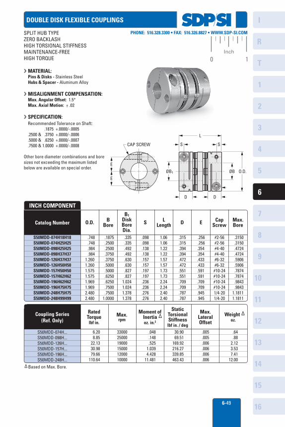
DOUBLE DISK FLEXIBLE COUPLINGS
SPLIT HUB TYPEZERO BACKLASHHIGH TORSIONAL STIFFNESSMAINTENANCE-FREEHIGH TORQUE
MATERIAL: Pins & Disks - Stainless SteelHubs & Spacer - Aluminum Alloy
MISALIGNMENT COMPENSATION:Max. Angular Offset: 1.5°Max. Axial Motion: ± .02
SPECIFICATION: Recommended Tolerance on Shaft: .1875 +.0000/-.0005 .2500 & .3750 +.0000/-.0006 .5000 & .6250 +.0000/-.0007 .7500 & 1.0000 +.0000/-.0008
Other bore diameter combinations and bore sizes not exceeding the maximum listed below are available on special order.
Catalog Number
Coupling Series(Ref. Only)
INCH COMPONENT
∆ Based on Max. Bore.
BBoreO.D. L
LengthCap
ScrewMax.BoreD ES
Moment of Inertia ∆
oz. in.2
Static Torsional Stiffnesslbf in. / deg
Max.rpm
RatedTorquelbf in.
Weight ∆oz.
Max.LateralOffset
B1DiskBoreDia.
S50MDD-074H18H18S50MDD-074H25H25S50MDD-098H25H25S50MDD-098H37H37S50MDD-126H37H37S50MDD-126H50H50S50MDD-157H50H50S50MDD-157H62H62S50MDD-196H62H62S50MDD-196H75H75S50MDD-248H75H75S50MDD-248H99H99
.3150 .3150 .4724 .4724 .5906 .5906 .7874 .7874 .9843 .98431.18111.1811
.335 .335 .492 .492 .630 .630 .827 .827 1.0241.024 1.3781.378
.748 .748 .984 .9841.2601.2601.5751.5751.9691.9692.4802.480
.1875 .2500 .2500 .3750 .3750 .5000 .5000 .6250 .6250 .7500 .75001.0000
.098
.098
.138
.138
.157
.157
.197
.197
.236
.236
.276
.276
1.061.061.221.221.571.571.731.732.242.242.402.40
.315
.315
.394
.394
.472
.472
.551
.551
.709
.709
.787
.787
.256 .256.354.354.433.433.591.591.709.709.945.945
#2-56#2-56#4-40#4-40#6-32#6-32#10-24#10-24#10-24#10-241/4-201/4-20
.005
.005
.006
.006
.006
.006
.048 .148 .525 1.039 4.42811.481
6.20 8.85 22.13 30.98 79.66110.64
S50MDD-074H...S50MDD-098H...S50MDD-126H...S50MDD-157H...S50MDD-196H...S50MDD-248H...
330002500019000150001200010000
30.90 69.51169.92216.27339.85463.43
.64 .88 2.12 3.53 7.4112.00
CAP SCREW
E
E
ØB1
S S
L
ØB O.D.
D D
I
R
1
2
3
4
5
6
7
8
9
10
11
12
13
T
14
15
166-50
PHONE: 516.328.3300 • FAX: 516.326.8827 • WWW.SDP-SI.COM
0 1Inch
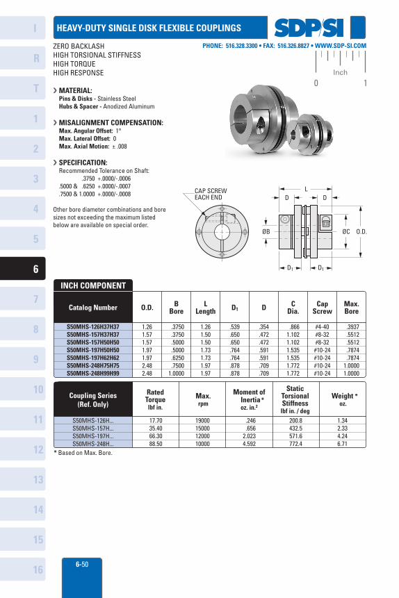
HEAVY-DUTY SINGLE DISK FLEXIBLE COUPLINGS
ZERO BACKLASHHIGH TORSIONAL STIFFNESSHIGH TORQUEHIGH RESPONSE
MATERIAL: Pins & Disks - Stainless SteelHubs & Spacer - Anodized Aluminum
MISALIGNMENT COMPENSATION:Max. Angular Offset: 1°Max. Lateral Offset: 0Max. Axial Motion: ± .008
SPECIFICATION:Recommended Tolerance on Shaft:
.3750 +.0000/-.0006.5000 & .6250 +.0000/-.0007.7500 & 1.0000 +.0000/-.0008
Other bore diameter combinations and bore sizes not exceeding the maximum listed below are available on special order.
Catalog Number
Coupling Series(Ref. Only)
INCH COMPONENT
* Based on Max. Bore.
BBore D1 D C
Dia.O.D. LLength
CapScrew
Max.Bore
Moment of Inertia*
oz. in.2
Static Torsional Stiffnesslbf in. / deg
Max.rpm
RatedTorquelbf in.
Weight *oz.
.8661.1021.1021.5351.5351.7721.772
.3750 .3750 .5000 .5000 .6250 .75001.0000
.354
.472
.472
.591
.591
.709
.709
.539
.650
.650
.764
.764
.878
.878
1.261.571.571.971.972.482.48
.3937 .5512 .5512 .7874 .78741.00001.0000
#4-40#8-32#8-32#10-24#10-24#10-24#10-24
17.7035.4066.3088.50
19000150001200010000
1.261.501.501.731.731.97 1.97
S50MHS-126H...S50MHS-157H...S50MHS-197H...S50MHS-248H...
S50MHS-126H37H37S50MHS-157H37H37S50MHS-157H50H50S50MHS-197H50H50S50MHS-197H62H62S50MHS-248H75H75S50MHS-248H99H99
ØC O.D.
D1 D1
LD D
ØB
CAP SCREWEACH END
200.8432.5571.6772.4
1.342.334.246.71
.246 .6562.0234.592
I
R
1
2
3
4
5
6
7
8
9
10
11
12
13
T
14
15
166-51
PHONE: 516.328.3300 • FAX: 516.326.8827 • WWW.SDP-SI.COM
0 1Inch
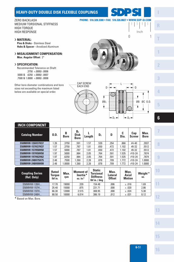
HEAVY-DUTY DOUBLE DISK FLEXIBLE COUPLINGS
ZERO BACKLASHMEDIUM TORSIONAL STIFFNESSHIGH TORQUEHIGH RESPONSE
MATERIAL: Pins & Disks - Stainless SteelHubs & Spacer - Anodized Aluminum
MISALIGNMENT COMPENSATION:Max. Angular Offset: 2°
SPECIFICATION:Recommended Tolerance on Shaft: .3750 +.0000/-.0006.5000 & .6250 +.0000/-.0007.7500 & 1.0000 +.0000/-.0008
Other bore diameter combinations and bore sizes not exceeding the maximum listed below are available on special order.
Catalog Number
Coupling Series(Ref. Only)
INCH COMPONENT
* Based on Max. Bore.
BBore
B1DiskBore
D1 D CDia.O.D. L
LengthCap
ScrewMax.Bore
Moment of Inertia*
oz. in.2
Static Torsional Stiffnesslbf in. / deg
Max.rpm
RatedTorquelbf in.
Weight *oz.
Max.LateralOffset
Max.Axial
Motion
.8661.1021.1021.5351.5351.7721.772
S50MHW-126H37H37S50MHW-157H37H37S50MHW-157H50H50S50MHW-197H50H50S50MHW-197H62H62S50MHW-248H75H75S50MHW-248H99H99
.3750 .3750 .5000 .5000 .6250 .75001.0000
.354
.472
.472
.591
.591
.709
.709
.539
.650
.650
.764
.764
.878
.878
1.571.811.812.052.052.282.28
1.261.571.571.971.972.482.48
.3937 .5512 .5512 .7874 .78741.00001.0000
#4-40#8-32#8-32#10-24#10-24#10-24#10-24
.591 .787 .787 .984 .9841.2601.260
154.48231.71308.95386.19
S50MHW-126H...S50MHW-157H...S50MHW-197H...S50MHW-248H...
1.692.865.308.12
.006
.008
.008
.012
.339 .8752.5156.014
17.7035.4066.3088.50
19000150001200010000
± .016± .020± .024± .031
CAP SCREWEACH END DD
L
ØB1
D1 D1
ØB ØC O.D.
I
R
1
2
3
4
5
6
7
8
9
10
11
12
13
T
14
15
16
PHONE: 516.328.3300 • FAX: 516.326.8827 • WWW.SDP-SI.COM
0 1Inch
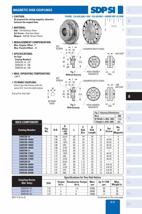
INCH COMPONENT
S50DCM-10S50DCM-10H02S50DCM-10H03S50DCM-10H04S50DCM-10H05S50DCM-17S50DCM-17H03S50DCM-17H04S50DCM-17H05S50DCM-20S50DCM-20H04S50DCM-20H05S50DCM-20H06S50DCM-20H08
Fig.No. O.D.
CHubDia.
DHub
LengthA Set
Screw
No.of
MagnetsL
BBore+.001 -.000
Catalog Number
1.371.371.37
146
1.458
425002600023000
.03
.08
.17
.22
.50
.60
Coupling Series(Ref. Only) OAL
Specifications for Two Hub Halves
Torquelbf in.
Max.rpm
S50DCM-10...S50DCM-17...S50DCM-20...
Breakaway Torquelbf in.
hp @ 1750rpm
Max.Weight lb.
.500BoreW Width (+.002/-.000)T Height (+.010/-.000)
Fig. 2 Keyway Dimensions
.1250
.560
AIR GAP*
OALHIGH ENERGY
MAGNETS
OAL
.188AIR GAP
HIGH ENERGYMAGNETS
O.D.ØC
AD
L
ØB
CHAMFER BOTH ENDS
Fig. 2 With Keyway
AD
L
O.D.
CHAMFER BOTH ENDS
ØC
ØB
Fig. 1 Without Keyway
SET SCREW
SET SCREW
T
W
KEYWAYDATA
MAGNETIC DISK COUPLINGS
CAUTION: Be prepared for strong magnetic attractionbetween the magnet hubs.
MATERIAL:Hub - 416 Stainless SteelSet Screw - Stainless SteelMagnet - NdFeB, Nickel Plated
MISALIGNMENT COMPENSATION:Max. Angular Offset: 3°Max. Parallel Offset: .25
SPECIFICATIONS:Air Gap* Catalog Numbers S50DCM-10: .125 S50DCM-17: .188 S50DCM-20: .188
MAX. OPERATING TEMPERATURE:+284°F
TO MAKE COUPLING:Select two hub halves with thesame O.D. from the table below.
Priced Per Hub Half
11111111111112
Continued on the next pageREV: 9.10.14 JC
1.061.061.061.061.061.721.721.721.721.971.971.971.971.97
.81
.81
.81
.81
.81
.81
.81
.81
.811.121.121.121.121.12
—#4-40#8-32#8-32#8-32
—#8-32#8-32#8-32
—#10-32#10-32#10-32#10-32
66666666688888
.63
.63
.63
.63
.63
.59
.59
.59
.59
.59
.59
.59
.59
.59
.25
.25
.25
.25
.25
.25
.25
.25
.25
.25
.25
.25
.25
.25
.12
.12
.12
.12
.12
.12
.12
.12
.12
.12
.12
.12
.12
.12
Solid.125.1875.250.3125Solid.1875.250.3125Solid.250.3125.375.500
6-52
I
R
1
2
3
4
5
6
7
8
9
10
11
12
13
T
14
15
16
PHONE: 516.328.3300 • FAX: 516.326.8827 • WWW.SDP-SI.COM
0 1Inch
11222122222
2.362.362.362.362.362.862.862.862.862.862.86
1.501.501.501.501.502.002.002.002.002.002.00
—#10-32#10-32#10-32#10-32
—#10-32#10-32#10-32#10-321/4-20
1010101010141414141414
.75
.75
.75
.75
.751.001.001.001.001.001.00
.35
.35
.35
.35
.35
.53
.53
.53
.53
.53
.53
.16
.16
.16
.16
.16
.28
.28
.28
.28
.28
.28
Solid .375 .500 .625 .750Solid
.500 .625 .750 .8751.000
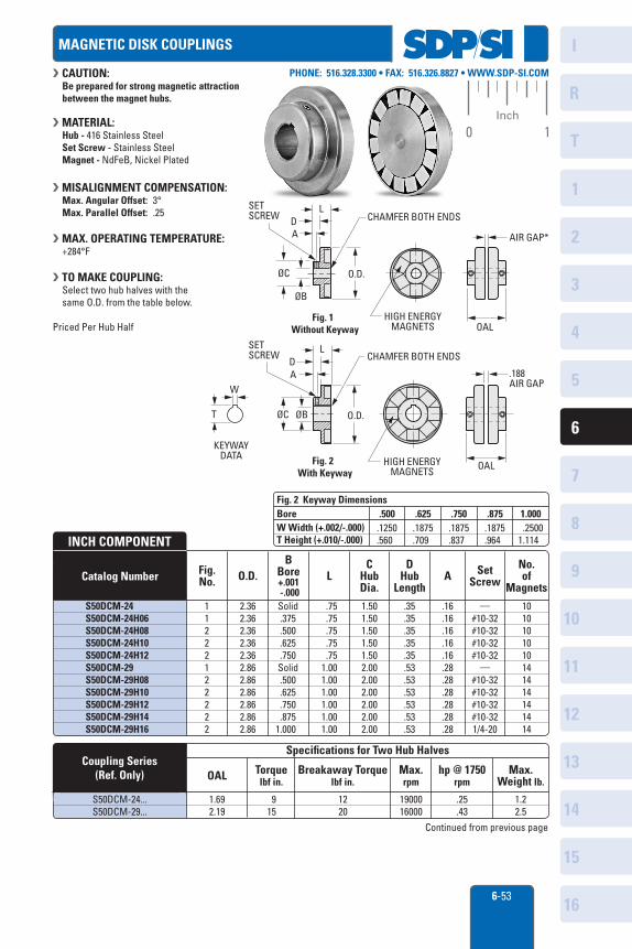
INCH COMPONENT
S50DCM-24S50DCM-24H06S50DCM-24H08S50DCM-24H10S50DCM-24H12S50DCM-29S50DCM-29H08S50DCM-29H10S50DCM-29H12S50DCM-29H14S50DCM-29H16
Fig.No. O.D.
CHubDia.
DHub
LengthA Set
Screw
No.of
MagnetsL
BBore+.001 -.000
Catalog Number
1.692.19
915
1220
1900016000
.25
.431.22.5
Coupling Series(Ref. Only) OAL
Specifications for Two Hub Halves
Torquelbf in.
Max.rpm
S50DCM-24...S50DCM-29...
Breakaway Torquelbf in.
hp @ 1750rpm
Max.Weight lb.
BoreW Width (+.002/-.000)T Height (+.010/-.000)
Fig. 2 Keyway Dimensions.625.500 .750 .875 1.000
.1875
.709.1250.560
.1875
.837.1875.964
.25001.114
MAGNETIC DISK COUPLINGS
CAUTION: Be prepared for strong magnetic attractionbetween the magnet hubs.
MATERIAL:Hub - 416 Stainless SteelSet Screw - Stainless SteelMagnet - NdFeB, Nickel Plated
MISALIGNMENT COMPENSATION:Max. Angular Offset: 3°Max. Parallel Offset: .25
MAX. OPERATING TEMPERATURE:+284°F
TO MAKE COUPLING:Select two hub halves with thesame O.D. from the table below.
Priced Per Hub Half
AIR GAP*
OALHIGH ENERGY
MAGNETS
OAL
.188AIR GAP
HIGH ENERGYMAGNETS
O.D.ØC
AD
L
ØB
CHAMFER BOTH ENDS
Fig. 2 With Keyway
AD
L
O.D.
CHAMFER BOTH ENDS
ØC
ØB
Fig. 1 Without Keyway
SET SCREW
SET SCREW
T
W
KEYWAYDATA
Continued from previous page
6-53