Embed Size (px)
Citation preview

II1IIII1
I
i
i
OPERATION MANUAL Donaldson,Ultrafilter®
*1
uitracool0400 Indigo
MI-089 rev.618.02.2004
Donaldson.

IIIIIIIIIII
Warnings
I
II ^^HHM «•""">•
I
I
I
11 I This Operation Manual is to be followed by all persons
working with the unit. It is imperative that this Manual is made_ freely available at all times to service personnel and is kept atI the point where the unit is installed.
The basic maintenance, as indicated in point 5.1, should becarried out by properly trained personnel and, if necessary,under the supervision of a person qualified for this job.
DItrafiiter personnel, or personnel authorised by ultrafilter,should carry out any work in the refrigerating or electriccircuit during the warranty period. After the warranty period,the work must be carried out by qualified personnel.
•i ^- 1 - oID

E
11111w1111111
1I V
I
111I
iBH HBii HHB
1
1 Table of Contents
Table of Contents1 Introduction
2 Installation
3 Start-up
4 Control Pane!
5 Maintenance
6 Troubleshooting
7 Technical Features
B Log Book
9 Annexes
10 Spare Parts
11 Technical Diagrams
1.11.2
2.12.22.32.42.52.6.2.7
3.13.23.3
4.14.24.2.1
5.1
6.1
7.1
8.1
9.1
10.1
11.111.211.3
General notesSafety regulations
Reception and inspectionTransportationSiteInstallationIdentification labels on the ultracool unit--Water connectionElectrical connection
Operating conditionsBefore the start-up of the ultracool unit *•Chiller start-up
Components of the control panelControl thermostatOperation
Basic maintenance
Possible causes of defaults
Technical Features
vs-Log Book
Water Quality
Spare parts
Dimensional sheetFlow sheetWiring sheet
33
4445566
778
91010
11
12
14
15
16
17
/l\. Points of special interest to keep in mind.
- 2 -

I
IIIIIIIIIIIIIII1IIII
Introduction
1 Introduction
1.1 General notes
• This water chiller complies fully with CE (50Hz version) and it is UL and C-ULapproved (60Hz version).
• The Company does not accept responsibility if safety regulations are not metduring handling, operation, maintenance and repair, even though these maynot be strictly stated in this operation manual.
• We recommend the translation of this operation manual into the nativelanguage of foreign workers. ---•
•. The usability and life cycle of the water chiller as well as avoiding prematurerepairs depends on proper operation, maintenance, care and competent repairunder consideration of this operation manual.
• We are constantly updating our products and are confident that they respondto the latest scientific and technological demands. However, asmanufacturers, we do not always know the end use or the total range of ourproducts' applications. Therefore we cannot accept liability for our products inapplications where additional safety measures may be necessary. We highlyrecommend that users inform us of the intended application in order toundertake additional safety measures, if necessary.
1.2 Safety regulations
The operator has to observe the national working, operating and safetyregulations. Also, existing internal factory regulations must be met.Maintenance and repair work must only be carried out by specially trainedpersonnel and, if necessary, under supervision of a person qualified for thiswork.
• Protective or safety devices must not be removed, modified or readjusted.
• During operation of the water chiller nohe'c5f the protective or safety'devicesmust be removed, modified or readjusted, temporarily or permanently.
• Only use correct tools for maintenance and repair work.
• Use original spare parts only.
• All maintenance and repair work must only be carried out to the machineonce it has been stopped and disconnected from the power supply. Ensurethat the water chiller cannot be switched on by mistake by unplugging it.
• Do not use flammable solvents for cleaning.
• Keep the surrounding area absolutely clean during maintenance and repairwork. Keep free of dirt by covering the parts and free openings with cleancloth, paper or adhesive tape.
• Ensure that no tools, loose parts or similar are left inside the system.
- 3

e
iiiiiiiiiiiiiii
Installation
2 Installation
2.1 Reception and Inspection
On receipt of the ultracool unit, it must be inspected for damage duringtransport. In the case of any damage, external or internal, this cannot bereferred to the manufacturer because all units are checked beforedispatch. If any damage is observed, this should be documentedand reported to the forwarding company. The ultrafilter warrantydoes not include any damages incurred during transportation.
The refrigerant circuit controls are set before shipment of the unit. Theyshould not be re-adjusted under any circumstances (except by anauthorized service agent). This would void the warranty of the unit.
2,2 Transportation
2.3 Site
Keep the unit upright at all times. Do not tilt when shipping or moving.The tilting of the ultracool unit may affect the internal suspensionof the refrigerant compressor.
The ultracool unit must be transported by palet jack or forkiift truck.
The ultracool unit must be installed in an atmosphere where the range oftemperatures is within the indicated margins mentioned in point 3.1. Forambient temperatures lower than 5°C (41°F) it is necessary to addethylene giycoi to the water of the circuit, as indicated in point 2.4.
We recommend the installation of the ultracool unit in a well-ventilatedsite and in a corrosive-free, dust-free atmosphere. * --
In the case of out-door installation the chiller must be protected from rainwith a roof and it must be installed in such way that the control panelreceives as few direct sunlight as possible.
Around the uitracool unit it should be left a space of 1,5 m (60"). It isimportant to facilitate maintenance work and cleaning, especially in frontof the condenser grid. The inlet of fresh air onto the condenser shouldbe in the most direct way possible, avoiding any chance of air recycling(the ceiling above should not be at less than 1,5m (60")).
IIIi
- 4
I
IIIIIIII
Iiiiiii
—
••
1
1
Installation
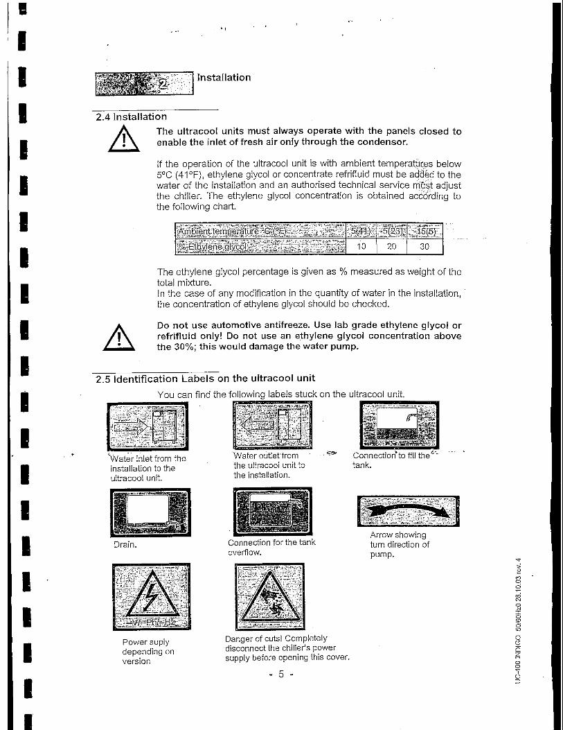
2.4 Installation
The ultracooi units must always operate with the panels closed toenable the inlet of fresh air only through the condenser.
If the operation of the uitracool unit is with ambient temperatures below5°C (41 °F), ethylene giycol or concentrate refrifluid must be added to thewater of the installation and an authorised technical service must adjustthe chiller. The ethyiene giycol concentration is obtained according tothe following chart.
Ambient temperature °C,(0E} ^ ~
% -Ethylene glycoi _' f w r^ ^
5(41)
10
:5(23)v
20
-15J5)
30
The ethylene giycol percentage is given as % measured as weight of thetotal mixture.In the case of any modification in the quantity of water in the installation,the concentration of ethyiene giycol should be checked.
Do not use automotive antifreeze. Use lab grade ethyfene glycoi orrefrifluid only! Do not use an ethylene glycoi concentration abovethe 30%; this would damage the water pump.
2.5 identification Labels on the uitracool unitYou can find the following labels stuck on the uitracool unit.
"Water inlet from theinstallation to theuitracool unit.
Water outlet'fromthe uitracool unit tothe installation.
Connection* to fill the''tank.
Drain. Connection for the tankoverflow.
Arrow showingturn direction ofpurnp.
Power suplydepending onversion
Danger of cuts! Completelydisconnect the chiller's powersupply before opening this cover.
- 5 -

eIIIIIIIIIIIIIII
COor-T
1oCO
O
IOii
Installation
2.6 Water Connection
It must be installed an external valve at the ultracool outlet in order toadjust the working pressure of the water pump. The pressure value isindicted in the chiller's data plate.
The water connection of the installation of the ultracool unit should becarried out according to the indications of the labels (stickers) present onthe unit.
The diameter of the inlet and outlet lines must be same size or largerthan those corresponding to the water inlet and outlet of the ultracooiunit. Always install thermal insulation for all pipes.
In the installations in which the water level of the circuit exceedsthe maximum level of the tank inside the ultracool unit, it will benecessary to install a check valve in the water outlet of theultracool unit and a solenoid valve in the water inlet. The supply ofthis solenoid valve will be carried out by terminals designed for thatpurpose (see electrical diagrams).
2.7 Electrical Connection
The electrical supply is 400V/3~/50Hz or 460V/3~/60Hz depending onthe version
It must be-checked that the supply voltage does not exceed a maximumvariation of 10% referring to nominal.
For the electrical supply of the ultracool unit, use an appropriate•electrical line Wording to the tiata in tite characteristics plate.
A system of fuses or circuit breakers must be installed before thepower inlet connection to the ultracool unit. The maximum size ofthese protections is defined in the electrical diagram.
There are two prepared terminals to connect a remote on-off switchaway from the unit. These terminals are at 24V.
There are two prepared terminals in order to connect a solenoid valve tothe water inlet to the ultracool unit, in such a way that when the ultracoolunit starts, the solenoid valve opens up. These terminals are at 24VAC.
- 6

IIIIIIIIIIII*
III
Iit))
II
Start-up
3 Start-up
3,1 Operating Conditions
The control thermostat in the chiller will control it in order to maintain thepreset cold water temperature.
Water temperature at the inlet:
Nominal:Maximum:
15°C{60°F)25°C (77°F)
Cold water temperature at the outlet:
Nominal: 10°C(50°F)Minimum: 5°C (40°F) (1)Maximum: 15QC(60°F)
(1) To reach this temperature it is necessary to add a 10% ethyleneglycol to the water and contact an authorised technical service to adjustthe chiller.
Temperature of the ambient air:
Nominal:Minimum:Maximum:
25°C (77°F)-15°C(5°F)(2)43°C(109°F)
(2) For ambient temperatures below 5°C (40°F) it is necessary to addethylene glycol to the water of the circuit (se,e. point 2.4).
3.2 Before start-up of the ultracool unit
Clean the application water circuit with tap water in order to be sure thatthere are no free particles. Otherwise the filter elements can block upduring the start up process.
The following points must be checked:
Lateral panels closed.Filling of the water circuit of the ultracool unit (see point 4.3).Water connections.Connection valves to the water line are open.External circuit protection is connected.
- 7 -

E
IIIIIIIIII
•II
-HI*IIIIIIII
Start-Up
3.3 Chiller start-up
When the ultracool unit is started for the first time, it is necessary to turnON the Main power switch (element 1 in the control panel, see point 4)and wait six hours before continuing with the start-up sequence. Thistime is necessary for the crankcase of the compressor to heat it up.
The oii in the crankcase of the compressor remains warm whenever themain power switch is in the ON position and the unit is connected to theline voltage. For this reason stop the ultracool unit by using the off-switch, leaving the Main power switch in the ON position.
Fii! the tank with water of the required quality (see annex 9) or withrefrifluid through the provided connection until the maximum level of thetank is reached.
Start the ultracoo! unjt,with-the On/Off switch (element 2 in the controlpanel, see point 4). Stop the ultracool unit and refill the tank to thecorrect water level.
Repeat this procedure until the water level in the tank remains constant.
It's necessary to verify the direction of rotation of the pump at theinitial start up. To do so, start and stop the ultracool unit, using theOn/Off switch (it is easier to see the turn direction when the pump isstopping). In the case of the pump rotating in the opposite direction fromthe indicated, it will be necessary to exchange two phases in the mainpower supply. It will not be necessary to check the turn direction of thefans, because they are delivered in phase with the pump. Since it maybe difficult to see the pump's rotation direction, verify that you did thisoperation correctly when the motor fan starts working: The air shouldenter the condenser and go out through the top of trie-chiller. If the air is'moving in the opposite direction then exchange two phases in the mainpower supply.
Connect the On/Off switch so that the ultracool unit starts. At the sametime the digital thermometer and all the indicators that should light up willturn on too, according to their function.
On the control thermostat select the desired temperature of the coldwater outlet (see point 4.2.1). The ultracool units are delivered with apre-set temperature of 10°C (50°F).
Adjust the water pressure, using an external valve at the ultracool outlet,to the value indicated on the data plate (Nominal pressure).
B
IIIIIIIIIIIIIIIIIIII
Control Panel
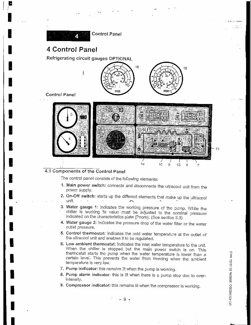
4 Control PanelRefrigerating circuit gauges OPTIONAL
Control Panel
4.1 Components of the Control Panel
The control panel consists of the following elements:
1. Main power switch: connects and disconnects the ultracoo! unit from thepower supply.
2. On-Off switch: starts up the different elements that make up the ultracoo!unit. • • *"•"
3. Water gauge 1: indicates the working pressure of the pump. While thechiller is working its value must be adjusted to the nominai pressureindicated on the characteristics plate (Pnom). (See section 3.3}
4. Water gauge 2: indicates the pressure drop of the water filter or the wateroutlet pressure.
5. Control thermostat: indicates the cold water temperature at the outlet ofthe uitracool unit and enables it to be regulated.
6. Low ambient thermostat: indicates the inlet water temperature to the unit.When the chiller is stopped but the main power switch is on. Thisthermostat starts the pump when the water temperature is lower than acertain level. This prevents the water from freezing when the ambienttemperature is very low.
7. Pump indicator: this remains lit when the pump is working.8. Pump alarm indicator: this is lit when there is a pump stop due to over-
intensity.9. Compressor indicator: this remains lit when the compressor is working.
- 9 -

IIIIIIIIIIIIIIIIIIIII
Control Panel
lO.Compressor alarm indicator: this is lit when there is a compressor stopdue to over-intensity,
11.Water level alarm indicator: this is lit when the water level in the tank istoo low. It causes the uitracool unit to stop.
12.Low flow/temperature control indicator: This flow control can stop thecompressor when there is no water circulation through the external watercircuit. In this case some flow still circulates inside the chiller. Thetemperature control can also stop the compressor when you try to reachwater temperatures below 7°C (45°F). To be able to reach temperaturesbelow that contact an authorised technical service.
13.Low refrigerant pressure alarm indicator: this is lit when the pressure ofthe refrigerating circuit (see element 15} is below the minimum allowed (1bar). It causes the refrigerant compressor to stop.
14.High refrigerant pressure alarm indicator: this is lit when the pressure ofthe refrigerating circuit {see element 16) is higher than the maximumallowed (27 bar). It causes the refrigerant compressor to stop.
15.Low pressure gauge: indicates the pressure at the low-pressure side ofthe refrigerating circuit (before the compressor).OPTIONAL
16.High pressure gauge:" indicates the pressure at the high-pressure side ofthe refrigerating circuit (after de compressor). OPTIONAL
4.2 Control Thermostat
Display in °C Display in,-y.Op
4.2.1 Operation
During normal operating conditions, the display of the controlthermostat shows the cold water temperature measured by theprobe. In the 50Hz version the display shows the temperature in °Cand in the 60Hz version it shows it in °F as depicted above.
Setting the temperature: Follow these steps to introduce the requiredworking temperature:
Hold down for 2 seconds the button SEL and the current settemperature will start flashing.
- To increase or to decrease the value of the setpoint, use the UP andDOWN buttons.Press SEL again.to confirm the new value.
If an alarm sounds: press the button PRG to silence the alarm. Thealarm code will stay until the cause of the alarm disappears.
-10

B
1
B '' ,
i
. ' j
Maintenance
•
• 5 Maintenance
15.1 Basic Maintenance
i
1
1
1
1
Weekly:"k>r^":•'•*>• ••':
Verify that the water temperature indicated on the control thermostat fsapproximately at the setpoint.
Verify the pressure of the pump.
Verify the water level in the tank.
Verify the state of the water filter, if the• psi) change the filter element.
Monthly:
With the Unit disconnected (Maincondenser with a blast of compressecoutside.
pressure drop exceeds 0.5 bar (8
power switch Off), clean theair, from the inside towards the
,;•, • Clean the housing, internally and externally, eliminating the dust present
iiiiiii
especially on the water pump rack.
Yearly:
Change the filter element and refill therefrifluid.
*r-»
,
water circuit with clean water or
t
I11 -
]

L_
v
Troubleshooting
6 TroubleshootingIn the following chart the possible causes for an alarm are given together with theirsolution:
DEFAULT
Alarm due to highpressure of therefrigerant the pressureof refrigerating circuit(see element 16 page10) is higher than themaximum allowed (27bar)
Alarm due to lowpressure of therefrigerant the pressureof the refrigerating circuitsee element 15 pagel 0)
is below the minimumallowed (1 bar)
Water level alarm
CAUSE
Lateral panels ofthe housing open
Low airflow intothe condenser
The ambienttemperature is toohigh
Water temperaturetoo high
Motor fan notworking
Gas leakage
Water leakage
SOLUTION
Close the panels
Clean the condenser
Wait until the ambienttemperature is lower
Try to cool down thewater in the circuitrunning the chiller withthe application stopped
Check the motor fanfuses. If the problempersists contactauthorised technicalservice.
Contact authorisedtechnical service.
Check the water circuitand refill the tank.
RESTART PROCEDURE
Disconnect the chiller(On/Off and Main powerswitch both Off, see point4). Open the front panel ofthe chiller and reset theHigh-pressure safetyswitch (SHP) by pressingits button. Turn both theMain power switch and theOn/Off switch back on.
Disconnect the chiller(On/Off and Main powerswitch both Off, see point4). Open the front panel ofthe chiller and reset theLow-pressure safety switch(SLP) by pressing, itsbutton. Turn both the Mainpower switch and theOn/Off switch back on.
The levei switchautomatically resets itselfwhen there is enoughwater in the tank
-12-

I
IIIIIIIIIIIIIIIIIII
\l Features
7 Technical Features
". ' • ' DC -
Cooling' capacityWater flowWater, pressureRefrigerant charge .Compressor :
Condenser • -. -Evaporator "
vlotorfan „, -
r ' "
Water-pump
-J ' '
max flowmin flow _
. max pres.
min pres.Water tank volume r ~
r tkW(ton)l/h (US gal/min)
bar (psi)kg.(Ib)-.
kW"'" •kW (ton)
- • ' kW(ton>- • •N°
KW(each|^ KW(totai)
m3/h (scfrn)
" .kW,
l/h (US gal/min)
bar (psi)
litre (US gal)Waterconnections '~ ~
Dimensions-FrontDepthHeight
WeightPowerVlax. fuse sizeVoltage
mm (in)rnm (in)"mm (in)-kg(lb)
kWA
V/P/Hz
Nominal COP
400 Indigo 50Hz:
43.1(12.2)7415(32.6)
4.8(70)28(62)10.8
69.9(19.8)47.4(13.5)
2
0.7
1.4
19000(11183)
2.6
14000(61.6)1400(6.2)5.9(86}3.8(55)300'(79)
1 /z" BSP1050(41)1610(63)1825(72)
560(1232}14.850
400/3/50 Hz3,53
400:Jn'digo.60Hz
39.8(11.3)6132(27)4.2(61}28(62)
14.771.1(20.2}40.1(11.4)
2
1.1
2.2
19000(11183)
2.1
16000(70.4)1600(7)4.5(65)2.5(36)321(85}
1 Vz" NPT1050(41)1610(63)1 825(72)
560(1232)19
50
460/3/60Hz2.35
All data related to the following conditions: Water outlet temperature 10°C (50°F) and ambienttemperature 25°C (77°F).
-14
I
1111I111111111111111
't
iiHil
. - f *
Log Book
8 Log Book
8.1 Log Book
Date.
v|;%
aM•"•?
Remarks
•-$• .
"^
1-
• . - • * -
•
Signature
-*• • •
-15-

IIIIIIII1IIIIIIIIIII
Annexes
9 Annexes
9.1 Water quality
In order to protect the water circuit of the ultracoo! units, the water to becooled must have specific physical/chemical properties so that it is notaggressive. If this water is outside any of the limits listed in the tablebelow, it can seriously damage some of the materials of the ultracoolunit.
Parameter
PHTotal Hardness (TH)
ConductivityNH3
Total iron ions (Fe^ and Fe""")Chloride (CJJ
H2SSolid particles
Limit values7-8
< 150 ppm50 - 500 tiS/cm
<2 ppm< 0.2 ppm< 300 ppm< 0.05 ppm< 150 M-m
The Total Hardness is specified in ppm (mg/L) of Ca2C03.
Please note that ultra pure waters like deionised water can also beharmful for some of the materials of the ultracool units as they have aconductivity below 50 jiS/cm.
The product refrifluid supplied by ultrafilter includes in its composition ananticorrosive, bactericide and antifreeze (until -7°C / 19.4 °F). It has thefollowing characteristics:
ParameterPH
Total Hardness (TH) . . .Conductivity
NH3
Total iron ions (Fe T and Fe'3"1")Chloride (CP)
H2SSolid particles
Limit values7.5
i<Ze < 30 ppip ,_ , _.50 p,S/cm
0 ppm< 0.2 ppm< 1 ppm0 ppm
< 50 urn
A concentration of ethylene-glyco! higher than the 30% can seriouslydamage the pump of the ultracool units.
ultrafilter will not accept any warranty for any damage caused bywater that is out of one or more of the above limits. Therefore, ifthere is not a total security on the water quality we advise the useof our product refrifluid. This fluid has been specially designed forthe protection of closed water circuits. Besides this ultrafiiter offersthe possibility of doing a basic analysis of a water sample suppliedby the customer.
- 1 6 -

B
I
EEEEEEEEEEEEE
IflflflE
Spare parts
10 Spare parts
-17

EDCMOTHDIGO.DWG
1355"
ELECTRICAL PANEL ACCES
1390 55" CONTROL PANEL
1610 63"
T105041'
USA VERS10H C£ VERSION
1.- 1 1/2" NPT WATER INLET2.- 1 1/2' NPT WATER COTIET
3.- 1/2' NPT TANK FILLING
4.- 1/2" NPT DRAIN AND OVERFLOW
WEIGHT: 1232 Lb
1.- 1 1/2" 8SP WATER INLET2.- 1 1/2' BSP WATER OUTLET
3.- 1/2" BSP TANK F1LUNO
4.- 1/2" BSP DRAIN AND OV5RFLOW
WEIGHT; 580 kg
DIMENSIONS IN mm (INCHES)
o
COo
o

-FLOW-DIAGRAM /'ULTRACOOL 0400 SP INDIGO
N°: 6637
DAT.:16.06.03
DIB.: A.Catalan
REV.: 5
DAT.:09.02.05
APR.iX.Escude
Ml - FREON COMPRESSOR
M2 - PUMP
M3/4 -
KM1
KM 2
KM3
KA1
KA2
KA3
KA5
QO
Ql
- COMPRESSOR CONTACTOR
- PUMP CONTACTOR
- MOTOR FANS CONTACTOR
- FLOW SWITCH TIMER
- ON/OFF INDICATOR RELAY
- ALARM RELAY
- LOW AMBIENT RELAY
- GENERAL SWITCH
'- COMPRESSOR CIRCUIT BREAKER
X2 2 9 12 14 15 16 18 20 22 28 32
Q2 - PUMP CIRCUIT BREAKER
F3 - MOTOR FANS FUSES
F1/2 - OPERATION CIRCUIT BREAKER
R1 - CRANK-CASE HEATER
31 - SWITCH ON/OFF
Bl -* SPEED REGULATORicONTtJOLLERi
B3/4 _ MOTOR FANS THERMOSTAT'
B5 - WATER LEVEL SWITCH
B7 - HIGH PRESSURE SAFETY SWITCH
B8 - LOW PRESSURE SAFETY SWITCH
B9 - LOW FLOW/TEMP. THERMOSTAT
B12 - LOW AMBIENT THERMOSTAT
24 VACUXX, 6A
- TRANSFORMER
- CONTROL THERMOSTAT
- WATER LEVEL ALARM INDICATORI
- FLOW. SWITCH ALARM INDICATOR* !• -
IPyEg.ypUTA'GE,RUMP ALARM INDICATORfeS'i'-
ALARM INDICATOR
- HIGfj PRESSU'RE1'ALARM"""INDICATOR
- LOW PRESURE ALARM INDICATOR
- COMPRESSOR ON INDICATOR
- LOW FLOW/TEMP. CONTROL INDICATOR
- PUMP ON INDICATOR
- SOLENOID VALVE
- SPEED REGULATOR
XI PE L1 L2 13 0 1 2 4 7 8 9 10 17 18 19 20 21 31 23 24 25 26 56 57 58
5QHz VERSION GOHz VERSION
k
Y
±'QO
L2 L3
16A
[Jjjj, pAX..!|! !|i IjiI I [
LI L2 L3
KM1
3.11
3.11
O IN+
_.®_ IN- /U
/^
V
^N
w
SR
1
A
10.SkW 18.1A (50Hz) 2.6kW 6A <50Hz)14.1 kW 19.6A (60Hz) 2,lkW 4.8A (6QHz)
0.7kV/ 1.6A 0.7kW 1.6 A 1.1 kW 1.9A 1.1 kW 1.9A
10
-O- 2.1
-O- 2.1
SHEET 1/3
12
IOoo
0O
o o— ;o-z. >3 s:o 'ho
B
IIIIIIIIIIII
c
IIIIIIIl
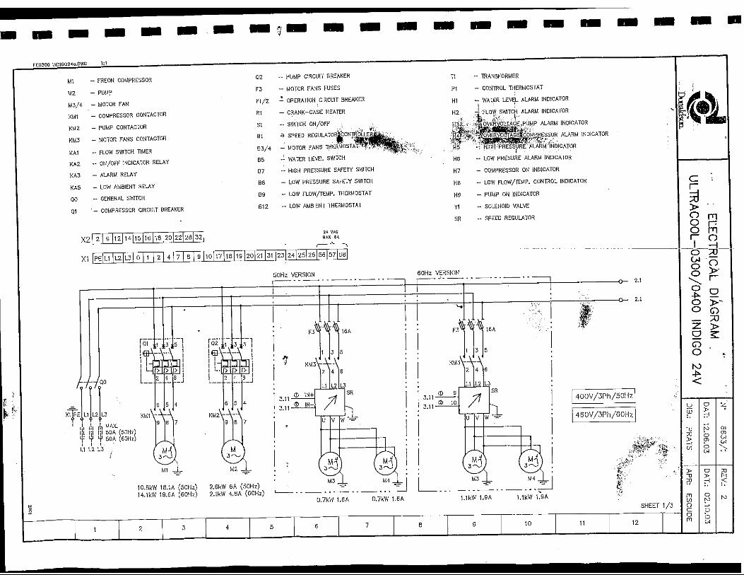
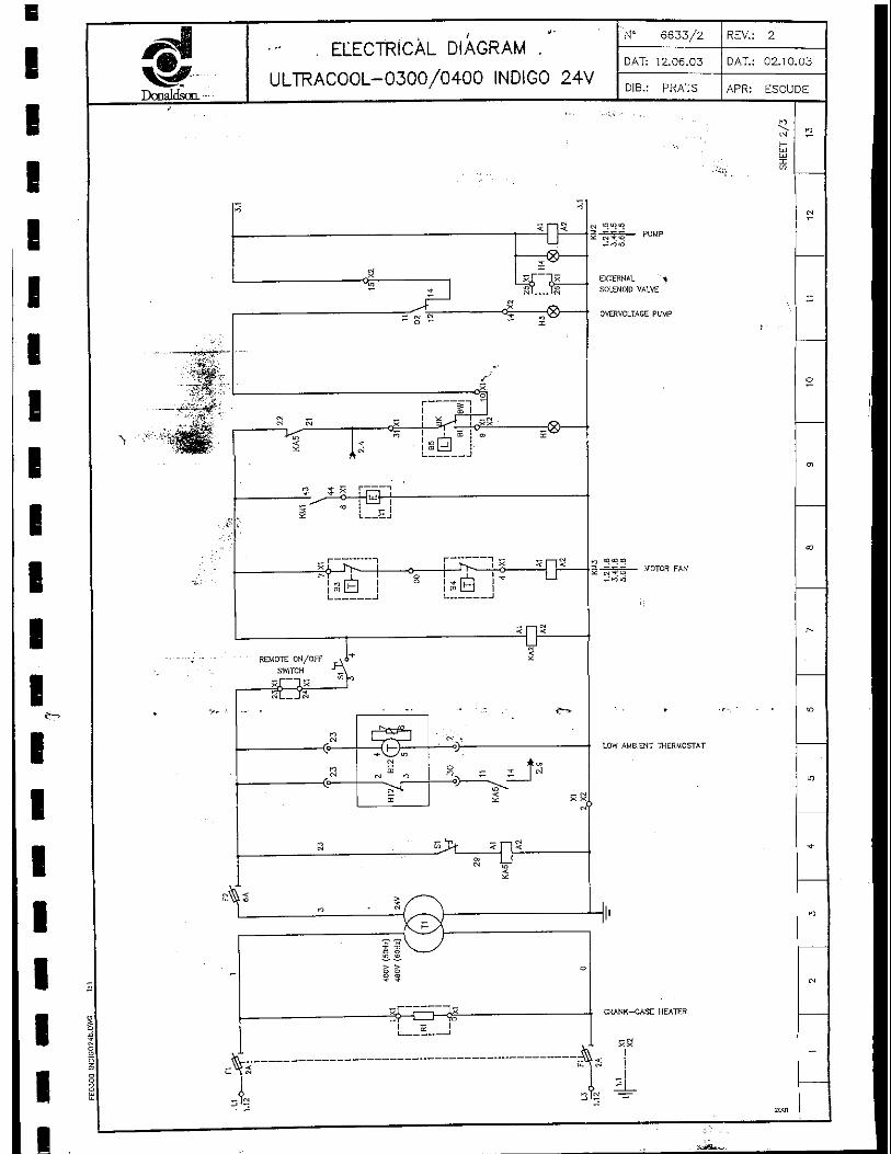
jgl •" . ELECTRICAL DIAGRAM . "
V# "" ULTRACOOL-0300/0400 INDIGO 24Donaldson. -
i
&
A
<
U
"~ * ST — JS
" a "- "" i
Si
as 1 1
-I-"""" 1 in -1 1 — <-*
A1^ i_™ 1
% i x r~ — " — '
5 M I T- lx i h.j
- f - ^ " " 1 r - ^ ~!^ s= n"
1 m l^~l m LJj |
• ' REMOTE ON/OFF JS* 1SWTCH -^A
CS 1 — ~ 1 OJ „
" Am
ff N m n "fi) " " 1 rf
E < _ CM
-t
ro ' ^ I \ §
i *-%
i; j
N' 6633/2 REV.: 2
DAT: 12.06.03 DAT.: 02.10.03
DIB.: PRATS APR: ESCUDE
• .-, i-Ul
EXTERNAL '^SOLENOID VALVE
OVERVOLTAGE PUMP
g ~ j~ — MOTOR FAN
XX
!i
woi
-
(N
^
O
01
CO
-
»
„
-
rO
IN
-

•
1111
i«11
1
11111
f~^
\11111
^^P^WB"A™m^ffV#r-Donaldson.
/
'•>"**'.'••„. 7^3
- ' , -.jja^
% ' .'H
..f
./ ^
£*•X
CMf?
«A<c^
' "•' ' 'N' 6633/3 S^REV.: 2nrrpTPiPAi niAPPAU " ;, C.LC.U 1 r\IUAI_ UIAor\MlVl .
DAT: 12.06.03 DAT.: 02.10.03
ULTRACOOL- 0300/0400 INDIGO 24V nlo nDATC.' . DIB.: PRATS APR: ESCUDE
'•••;^!
^ 5mm
IN^ <& s — s,! (N
c? -•~Vi/'Nm ^- m T"
.:. g
E /-." ^/^S« ^K c [ 3
' - , • _,. oi
'£'"^! • ^ ^/O\ ^-v
^'" • fts -- « (? \"5:- -to- " P LJ _-' '- ? \- o)
F»\P^V^^ R ^*.- '4< E „ c |
Jsp-e /-.<M -s\5 r^Tt ns <>]- og rn1 M <ycot - SB N s.* •u>^ . . . . . - .^> ,- ,-> CM
*c -c
n•cM
1 •* ! QX
i --f^ ! x>t, /o,! — T11 T N 1 o "<>
c i J-. i S • t3 1S0 !
1 rJ 1
-?1 1 ^ ^ 1 co0 *<>~ ! _J_. ! - toi ^ foil ' ^
rlSJ j
-*-
^ ^ vOj^ « 2 ^^
5
S
lo
n
• or-l
.". ". n
LJ• ui
Xin
/$>'-:'-
SPEED REG. CONTROLLER
LOW FLOW/TEMP. THERMOSTAT
CONTROL THERMOSTAT
CM CJ CS
x N-*<D— n<n
LOW FLOW/TEMP.
•' - - - -..-.*, • . .
LOW PRESSURE
HIGH PRESSURE
OVERVOLTAGE COMPRESSOR
2D01
IO
<N
^
O
cn
CO
•
ID
1O
-t-
IO
(N
-

EC Declaration of conformity J - GB
B9/392/EEC (Known as the 'Machinery Directive')
91/368/EEC (Amendment to the 'Machinery Directive')
93/44JEEC (Amendment to the 'Machinery Directive')
97/23/EC (Defined by pressure equipment directive)
ultrafilter, S A
Based in Terrassa-Barcebna-Spain, Colom II
Street n° 606, Postal Code 08228
Declares that under our sole responsability for1 supply/manufacture of the product:
Name Model Serial-Mr
ultracool-0400SP CE E6812022-90
To which this declaration relates, is in conformity with
the Directive 89/392/EEC issued by the EUROPEAN
COMUN1TY of the 14th. of June 1.'989,
ECKcnformitatsErklarung1 D
89/392/EEC (Bekannt als 'Maschinen Weisung')
91/368/EEC (Anderung air 'Maschinen Weisung')93/44/EEC (Anderung zur 'Maschinen Weisung')
97/23/EC (Defeniert in der Druckgerateverordnung)
ultrafilter, S A
Mil S'rtz in Terrassa-Barcelona-Spain, Colom II
Strasse, nr. 606, Postfach 08228
Erkiart, daB unserer alieinigen Verantwortung
unteriiegt, das LJefeiung/Herstellung des Produktes;
Name Modell Serien-Nr
uitracool-0400SP CE E681 2022-90
Auf welches diase Erkiarung Bezug nimmt den erlassenen
Weisungen 89/392/EEC der EUROPAlSCHEN
GEMEINSCHAFT vom 14. Juni 1989, entspricht.
Declaration de conformite CE j F
89/392/EEC (connue cotnme 'Directive Machine')
91/368/EEC (Amendment a la 'Directive Machine')93/44JEEC (Amendment a la 'Directive Machine')
97/23JEC (Defini par la directive des equipements sous
pression)
ultrafilter, S A
Domidlie a Terrassa-Barcelona-Espagne, rueColom II, no. 606
Declare sous sa seule responsabilite defoumisseur/fabriquant du produit:
Norn Model Serial-Nr
ultracool-0400SP CE E6812022-90J
Objet de cette declaration, est en conformite avec la
Directive 89/392/EEC issue de la COMMUNAUTE
EUROpEENNELE14Juin 1.989,
III
C€ Dedaracion de conformidad CE
89/392/EEC (Conocida como 'Directiva de maquinaria')91/368/EEC (Revision de la 'Directiva de maquinaria')
93/44/EEC (Revision de la 'Directiva de maquinan'a')
97/23IEC (Definida por la directiva de equipos a presion)
ultrafilter,* S A
Con sede en Terrassa-Barcelona-Espafia.calle
Colom II n° 606, C.P. 08228
Dedara que, bajo nuestra responsabilidad como
proveedores/fabricantes, el producto:
Name Model Serial-Nr
[ ultracool-04QQSP CE E6812022-9Q j
Es conforms a la Directiva 89/392/EEC establecida a
14 de Junio de 1989 por la COMUNIDAD ECON6MICA
EUROPEA.
EC Verklaring van conformiteit NL
89/392/EEC (Bekend als 'machine richtljjn')91/368IEEC (Rectificatie van de 'machine richtlljn')
93/44/EEC (Rectificatie van de 'machine ricntlijn)
97/23/EC (Ontworpen volgens de Pressure Equipment
Directive - richtlijnen)
ultrafilter, SA.
Gezeteld in Terrassa-Barceiona-Spanje, Colom II
Straat nr. 606, Postcode 08228
Verklaart dat onder volledig eigen verantwoordelijkheid
voor de levering/fabricage van onderstaand product
Naam Model Serienummer
[ ultracocWOOSP CE E6812022-90
Waartoe deze verklaring behoort, conform is aan de
richtlijn 89/392/EEC, uitgegeven door de EUROPESE
GEMEENSCHAP op Hjuni 1989.
f Dichiarazione di conformita CE j I
89/392/EEC (conforme alia 'Direttiva Macchine'j91/368/EEC (emendamento delta 'Diretflva Macchine')
93/44/EEC (emendamento delta 'Direttiva Macchine')
97/23/EC (Definite dalla direttiva dei recipient! a pressione)
ultrafitter, SA.
Colom II Street n° 606, Terrassa-Barcetona Codice
Postale 08228
Dichiara ia responsabilrta per la produzione prodotto:
Nom Model Serial-Nr
[ ultracool-Q40QSP CE E6 81 2022-9 o
II contenuto della presente relazione e in conformita con
la Direttiva 89/392/EEC della COMUNITA EUROPEA
deM4giugno1989.
( ^Q^ [ ECProhlasenioshode .] CZ
, 89/392/EEC- .(Machinery Diraplives)- -91/36E/EEC (Machinery Directives, priioha)
93/44/EEC (Machinery Directives, priioha)
97/23IEC (Definovano smemici pro tlakova zafizeni)
ultrafiKer. SA
Se sidlem Terrassa-Barceiona-Spain, Colom II Street,n° 606, Postal Code 08228
Z titulu sve odpovednostl '/yrobce a dodavatele prohlasuje
ze toto prohlaseni o shode se vztahuje k zarizeni:
Typ Model Seriove cislo
[ uitracool-0400SP CE E6812022-90 J
A je pine v souladu se srnemici Evropskeho
spolecenstvi c. 89/392/EEC ze dne I4.cervna 1989.
^ J
, a
/" AC€ f EC Overensstemmetseserklajring j DK
89/392/EEC (Kendt som 'Maskindirektivet')
91/363/EEC (Tillsg tl 'Maskindirektivet1) •
93/44JEEC (Tilteg til 'Maskindirektivet')
37I231EC (Defineret at direktivet for trykluftudstyr)
ultrafilter, SA
Bosiddende i Tenassa-Barcelona-Spain, Colom 11Street, n° 6Q6, Postal code 08228
Erkterer under eneansvar for levering/fremstilling afproduktet;
Navn Model Sen'enummer
[ ultracooi-G400SP CE E6812022-90 J
Hvortil denne erktering relaterer, at produktet er i
overensstemmelse med Direktivet 89/392/EEC udstedt
af det EUROP/EISKE F/ELLESSKAB d. 14. juni 1989.V ' J
f
^^^^=:
. i
-*?=.
f ^C € [ EC Declaratie de Conformitate 1 RO
_^ 39/392^EC (Cunoscuta t^f 'Directiva Con^TS-Jiilor da M-tsinF)
91/368/EEC [Amendamert la 'Directiva Construct! ilor de Masini1)
93/44/EEC (Arnendament la 'Directiva Constructiiior de Masini')
97/23/EC (Conform reglementarilor de utilizare a
echipamentelor sub presiune)
ultrafilter, SA.
Domicilie a Terrassa-Barcelona-Espagne, rueColom II, no. 606
Dedara pe proprie raspundere ca fumizarea/
fabricarea produsului:
Nurne Model Nurnar Serial
( ultracool-G400SP CE E6812022-90 }
La care se refera aceasta declaratie este in
confomiitate cu Directiva 89/392/EEC emisa de
COMUNITATEA EUROPEANA la 14 lunie 1989.^ J
__— — „. ^
ultrafilterEnergy and
environmental technology.
Xavi Escude Jr.
Technical Director