Embed Size (px)
Citation preview
Unit-IV: Electromagnetic Induction and Alternating Currents
I_ -·. ·--·· ..
Electromagnetic Induction
Magnetic Flux (~,,) Electro.magnetic Induction Types gf Electromagnetic Induction and Il'lductance Some Applications of Electromagnetic
· Induction Short-Answer Questions Multiple Choice Questions (with Hints and Solutions) Assertion-Reason Type Questions
9.1 Magnetic Flux (<\>8) _, _,
Magnetic flux 'PB through an area ds in a magnetic field B is defined as
'PB= J B-~ Physically it represents total lines of induction passing
through a given area. Regarding magnetic flux it is worth noting that:
(!) Though Jines of force are imaginary, flux is a real scalar physical quantity with dimensions
[<jlB]=[B][S]=[~}S] [asF=B/Lsin0]
i.e., ['PB]=[ ML~-2 }L2]=[ML2T-2A-1] ... (!)
(2) As [ML2T-2]corresponds to energy, SI unit of magnetic
flux will be
joule joule x sec [ coulomb] = as ampere=
ampere coulomb sec
= volt x sec [as (joule/coulomb)= volt]
and is called weber= (Wb) or T-m2 (as tesla = Wb/m2). As I volt = 108 emu of potential, the CGS unit of flux, maxwell (Mx) is related to weber (Wb) through the relation
I Wb= I Vxs= 108 emuofpotxs= 108 Mx ... (2) _,
(3) As magnetic flux associated with elemental area ds [Fig. _,
9.1 (A)] in a field B, _, _,
d<jlB=B-ds=Bdscos0 ... (3) So for a given area (a) it will be maximum when cos 0 =
_, maximum= I, i.e., 0 = 0°, i.e., magnetic field Bis normal to the area with
a Publications Pvt. Ltd., Delhi
GRB (NEET) with www.puucho.com
www.puucho.com
GRB Physics for Me.dical Entrance Exams (2nd Year Programme) ' '
. ~ ds___ B =ir,r f 8 '-,~· -
LDL IL I d$8 = B ds case
(A)
(d$alm~ = B ds
(8)
(d$alm1n = 0
(C) Fig, 9.1
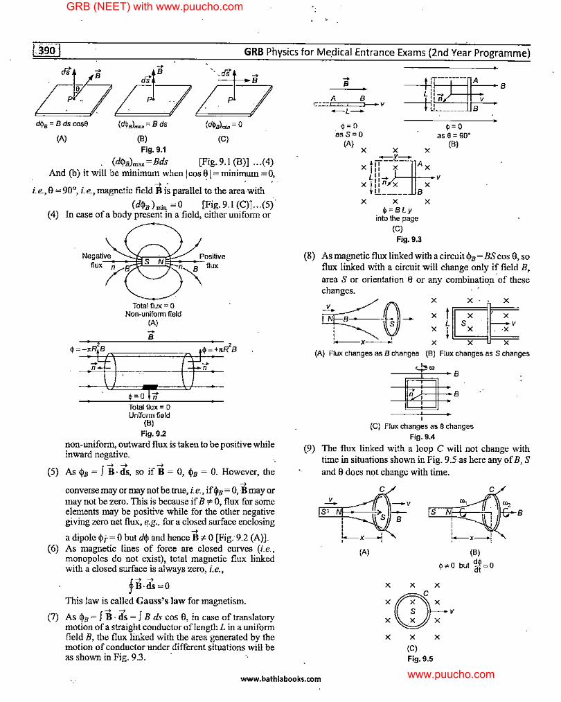
(d$B)max=Bds [Fig, 9.1 (B)) ... (4) And (b) it will be minimum when I cos 8 I.= mini~um = 0,.
_, ' i.e., 8 = 90°, i.e., magnetic field Bis parallel to the area-with
(d$B)nrin =0 [Fig,9.1 (C)] .. ,(5) (4) In case ofa body present in a field, either uniform or
(5)
Total flux= O Non-uniform field
(A) -B
Total flux= O Uniform field
(8) Fig, 9.2
non-uniform, outward flux is taken to be positive while inward negative. ..
f_, _, _,
As $B = B-· ds, so if B = 0, $B = 0. However, the _,
converse may or may not be.true, i.e., if $B = 0, B may or may not be zero. This is because if B * 0, flux for some elements may be positive while for the other negative giving zero net flux, e.g., for a closed surface enclosing _, a dipole $i-=0 but d$ and hence B'F0 [Fig:9.2 (A)).
(6) As magnetic lines of force are closed curves (i.e., monopoles do not exist), total magnetic flux linked with a closed surface is always zero, i.e.,
fB-ds=O
This law is called Gauss's law for magnetism.
(7) As $ B = f B · ds = f B ds cos 8, in case of translatory motion of a straight conductor oflength L in a uniform field B, the flux linked with the area generated by the motion of conductor under different situations will be as shown in Fig. 9.3. ·
-B
A B =:E::::=::::5-v -L-
$=0 asS=O
(A) X X
-r-
as0=9O°
X (8)
x t ::-:i--]A X LH- V
X ill:_:__ BX
X X X $=BLy
into the page (C)
Fig, 9.3
(8) As magnetic flux linked with a circuit $B = BS cos 8, so flux linked with a circuit will change only if field B, area S or orientation 8 or any combination· of these
(9)
changes. ·
r;rE::G--x-: tmX··,:
L S . V X i X. . ,X
X X X (A) Flux changes as B changes (8) Flux changes as S changes
<-J:>ro
~: I
(C) Flux changes as 0 changes Fig, 9.4
The flux linked with a loop C will not change with time in situations shown iu Fig. 95-as here any of B, S and 8 does not change with time.
(A)
S N ' ' ' '
.,, C
f..--x-! (8)
$s<O but 'M=o X X X
:~v X X
(C) Fig.9.5
X
B
www.bathlabooks.com
GRB (NEET) with www.puucho.com
www.puucho.com
Electromagnetic Induction .
i.e., qi= BS c~s 8 = B(NrtR2) cos 0°
= NrtR2 B = constant
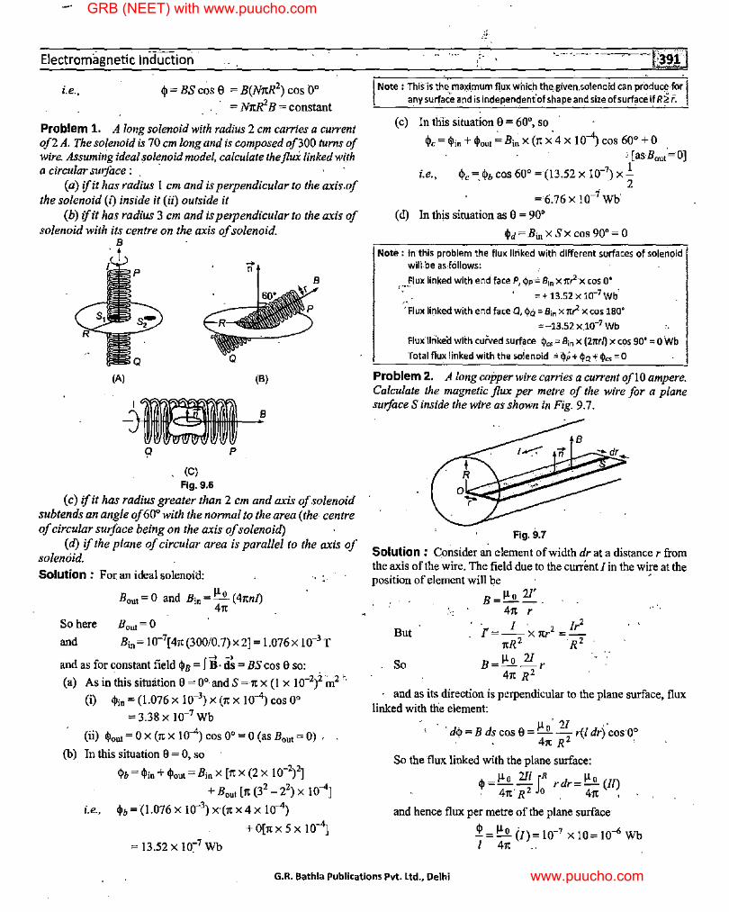
Problem 1. A long solenoid with radius 2 cm carries a current of2 A. The solenoid is 70 cm long and is composed of300 turns of wire. Assuming ideal solenoid model, calculate the flux linked with a circular surface : . ·
(a) ifit has radius I cm and is perpendicular to the axis.of the solenoid (i) inside it (ii) outside it
(b) ifit has radius 3 cm and is perpendicular to the axis of solenoid with its centre on the axis of solenoid.
B
t
(A)
. (C) Fig. 9.6
-n
(B)
B
(c) ifit has radius greater than 2 cm and axis of solenoid subtends an angle of60° with the normal to the area (the- centre of circular surface being on the axis of solenoid)
(d) if the plane of circular area is parallel to the axis of solenoid. Solution : For an ideal solenoid:
So here
and
Bout= 0 and Bin= !:':.,Q__ ( 411n/) 411
Bout= 0 Bin= 10-7[411(300/0.7)x2] = 1.076X 10⁻³ T
f -+ -+ and as for constant field <j>8 = B · ds = BS cos 0 so:
(a) As in ;his sitnation 0 = 0° and S = 11 x (l x 10-2)2 m2 ,,
(i) <!>in= (1.076 X 10-3) X (11 X 10-4) COS 0°
= 3.38 X 10⁻⁷ Wb
(ii) <!>out= 0 X (llX 10-4) cos 0° =O (asBout=O) ,
(b) In this sitnation 0 = 0, so
<l>b = t\lin +<!>out= Bin X [11 X (2 X 10-2)2] + Bout [11 (32
- 22) X 10-4]
i.e., q>b = (1.076 X 10-3) X (11 X 4 X 10-4)
+ 0[11 X 5 X 10-4]
= 13.52 X 10~7 Wb
·-··· ·.- . -
I Note : Th. is·is the,_maxi_ffium flu.x w.hich tlie .. given.so. lenaid can pr_~du.ce." ~r I l any surface and is lndependenfof shape and size of surf~ce if R;?:; r.
(c) In this sitnation 0 = 60°, so
<l>c= <l>in +<l>out,;,Binx (11 X0
4 X IO-") cos 60° +O '[asB0u."=O]
i.e., <l>c = <l>b cos 60° =(13.52 X 10⁻⁷) X .!. . ' 2
= 6.76 X 10-i Wb
( d) In this sitnation as 0 = 90°
(\ld=Bin xSx cos 90°= 0
Note: In this problem the_ flux linked With different surfaces of solenoid will"be asJcillows:
Flux linked with end face P, q>p = Bin-X nr2x cos 0° ,.,,., = + 13.52 X 10⁻⁷ Wb0
·:·Flux linked with end face Q, 4>6 = Bin x nr2 x cos 180°
= -13.52 x.10-7 Wb
FluxJl11kecl with curved surf_ace 4>cs-== Bin x (27trl) x cos go•= O Wb
Total flux linked with the soienoid = c!>P +$a+ ¢Jes= 0
Problem 2. A long copper wire carries a current oflO ampere. Calculate the magnetic flux per metre of the wire for a plane surface S inside the wire as shown in Fig. 9. 7.
Fig.9.7
Solution : C.onsider ~ element of width drat a distance r from the axis of the wire. The field dne to the current fin the wire at the position of element will be ,
B=µ" 21'. 411 r
· I ' Ir2
But I'=--x11r2 =-11R2 R2
So B=µ" l!...r 411 R 2
and as its direction is perpendicular to the plane surface, flux linked with the element:
' ' ' µ , 21 ,, ·, d<j> = B ds cos 0 = - 0
- r(ldr) cos ·0° · - 411 R 2
•
So the flux linked with the plane surface:
<1>=µ 0 211 JR rdr=µ" (II) . 41t'R 2 o . 411 ,
and hence flux per metre of the plane surface·
_P. = µO (/)= [0-7 X [0= 10-6 Wb 1 411 ..
G.R. Bathla Publications Pvt. Ltd., Delhi
GRB (NEET) with www.puucho.com
www.puucho.com
. GRB Physics for Medical Entrance Exams {2nd Year Programme)
Note : As ill terms· of self-Inductance L, $ = LI, self-Inductance of a c'ylindrical wire of length/:
L=1=µ•(ij andso £=µ•=10-1 ~ I 41t ,/ 41t m
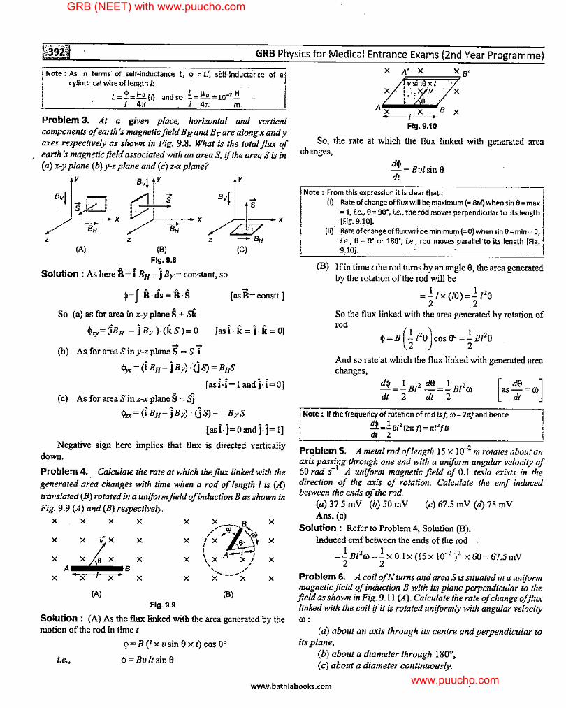
Problem 3. At a given place, horizontal and vertical components of earth 's magnetic field B Hand B v are along x and y axes respectively as shown in Fig. 9.8. What is the total flux of earth 's magnetic field associated with an area S, if the area S is in (a) x-y plane (b) y-z plane and (c) z-x plane?
y ~1r j Bv! sD c9 ~ x Bv! ~x X /T b -BH
z z z -BH (A) (B) (C)
Flg.9.B
Solution: As here B= i BH-}Bv= constant, so
q,=J B·ds=B·S So (a) as for area inx-yplaneS +Sk
q>xy=(i.Bn -}Bv )·(kS)= 0
-+ -+ (b) As for area S in y-z plane S = S i
-+ [ as B = constt.]
[asi·k=j·k=OJ
i-z"" (i BH- jBv) ·°(jS) =BHS
[asi-i= I and]-i=O]
(c) AsforareaSinz-xplaneS=.sJ
<j,,,.= (i BH-JBv) · (jS) =-BvS
[as i· }= 0 and j-j= I]
Negative sign here implies that flux is directed vertically down.
Problem 4. . Calculate the rate at which the flux linked with the generated area changes with time when a rod of length I is (A) translated (B) rotated in a uniform field of induction Bas shown in Fig. 9.9 (A) and (B) respectively.
X X X X X x ___ B X
/ i~ 1 / r- ' ,«g,
X X X { X 9, 'I X
X X X X l A-1=..:
X \ X X I A B
\ , ' , X -X-I~ X X x-----..-x X
(A) (B) Flg.9.9
Solution: (A) As the flux linked with the area generated by the motion of the rod in time t
i.e.,
q,=B (Ix usin 8xt) cos 0°
q, = Bult sin 8
X A' X X B' , vsiti8xt
X : · .. X .V X I' ,- ' ,_ , a·
Ax'x-·Bx ~,-Fig. 9.10
So, the rate at which the flux linked with generated area changes,
dq, 1'8 -=Bu sm dt
Note : From.this expression it Is clear that: (i) Rate of change offluxwill be maximum(= Bvl) when sin 8 = max
=-1, i.e., 8 = 90°, i.e., the rOd moves perpendicular to .its.length (Fig. 9.10]. I
(Ii), Rafe of change offlux,wili be mln-imum (= 0) wheri sin 8::; min= 0, -./!e., 0 = O" or· 180°, Le., rod moves parallel ·to its length [Fig. ii
9.10]. - -
(B) !fin time t the rod turns by an angle 8, the area generated by the rotation of the rod will be
I I 2 =-lx(/8)=-18
2 .2 So the flux linked with the area generated by rotation of rod
And so rate ·at which the flux linked with generated area changes,
I Note : If the frequency of rotation of.rod Is/, ro = 2n/ and hence
i d~=!8/2 (21t/)=1t/2/8 / dt 2
Problem 5. A metal rod of length 15 x 10-2 m rotates about an axis passing through one end with a uniform angular velocity of 60 rad s-1
• A uniform magnetic field of 0.1 tesla exists in the direction of the axis of rotation. Calculate the emf induced between the ends of the rod,
(a) 37.5 mV (b) 50 mV (c) 67.5 mV (d) 75 mV Ans. (c)
Solution.: Refer to Problem 4, Solution (B). Induced emf between the ends of the rod
=_I_ Bt'ro=_I_ x O.Ix (15x 10-2 )2 x 60= 67.5mV 2 2
Problem 6. A coil ofN turns and area Sis situated in a uniform magnetic field of induction B with its plane perpendicular to the field as shown in Fig, 9.11 (A). Calculate the rate of change of flux linked with the coil if it is rotated uniformly with angular velocity 0):
(a) about an axis through its centre and perpendicular to its plane,
(b) about a diameter through 180°, (c) about a diameter continuously.
www.bathlabooks.com
GRB (NEET) with www.puucho.com
www.puucho.com
Electromagnetic Induction
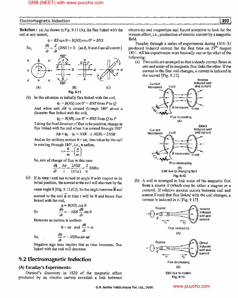
Solution : (a) As shown in Fig. 9.11 (A), the flux linked with the coil at any instant,
<I>= BS cos 0 = B(NS) cos 0° = BNS
So, d<I> =i_ (BNS)= 0 [asB,NandSareallconstt.] dt dt
180°
X
* X ~ B Qrn: B ,f,l' e~B X®)(- n :: - -L, --'-' _,_: - ~ I ', n
'-V A B L! X X X
(A) 180°
(B) Fig. 9.11
(C)
(b) In this situation as initially flux linked with the coil,
<1>1 = B(NS) cos 0° = BNS from P to Q And when coil AB is rotated through 180° about a diameter flux linked with the coil,
<1>2 = B(NS) cos 0° = BNS from Q to P Taking the final direction of flux to be positive, change in flux linked with the coil when it is rotated through 180°
A<I> = <l>2 -<1>1 = NSB-(-NSB) = 2NSB
And as for uniform motion 0 = rot, time taken by the coil in rotating through 180°, i.e., 1t radian,
/=~=(;) So, rate of change of flux in this case
d<I> = A<I> = 2NSB = ~ NSBw dt t (1t/(J)) 1t
(c) !fin time t coil has turned an angle 8 with respect to its initial position, the normal to the coil will also tum by the
same angle 0 [Fig. 9.11 (C)]. So the angle between Band _,
normal to the coil n at time I will be 8 and hence flux linked with the coil,
<I> =B(NS) cos 0
So d<i> =-NSB de sin8 dt dt
However as motion is uniform
B=rot and dB =ro dt
So, d<I> = - NSBw sin rot dt
Negative sign here implies that as time increases, flux linked with the coil will decrease.
9.2 Electromagnetic Induction
(A) Faraday's Experiments: Oersted's discovery in I 820 of the magnetic effect
produced by an electric current revealed a link between
electricity and magnetism and forced scientists to look for the inverse effect, i.e., production of electric current by a magnetic field.
Faraday through a series of experiments during 1831-32 produced induced current for the first time on 29th August 1831. All his experiments were basically one or the other of the following:
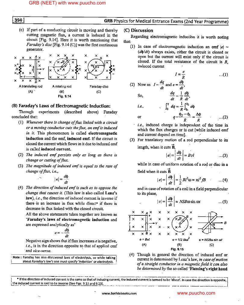
(a) Two coils are arranged so that a steady current flows in one and some of its magnetic flux links the other. If the current in the first coil changes, a current is induced in the second [Fig. 9.12].
Inverse Current Induced emf
increased I coil and current
-Pt,,, ~3]: ?~ B increases II coil
Flux increasing (A)
Direct Current Induced emf
decreased I coil and current
Jt,~ Flux decreasing
(B) EMI due to changing field
Fig. 9.12
(b) A coil is arranged to link some of the magnetic flux from a source S (which may be either a magnet or a current). If relative motion occurs between coil and source S such that flux linked with the coil changes, a current is induced in it [Fig. 9.13].
Source ~-Inverse -0 or ~ Induced S emf and
_ _ current V1 V2
Flux increasing
(A)
Source ~ Direct -0 or~ Induced S emf and
_ _ current V1 V2
Flux decrea~ing
(B)
EMI due to motion Fig. 9.13
G.R. Bathla Publications Pvt. Ltd., Delhi
GRB (NEET) with www.puucho.com
www.puucho.com
GRB Physics for Medical Entrance Exams (2nd Year Progrnmme)
X
( c) If part of a conducting circuit is moving and thereby cutting magnetic flux, a current is induced in the circuit [Fig. 9.14]. Here it is worth mentioning that Faraday's disc [Fig. 9.14 (C)] was the first continuous generator.
Ax X X X
+ X x+ X
x1f X +
R R V x_ X X ·x
X X
A translating rod (A) ..
A rotating rod
(B)
Fig. 9.14
Faraday-disc
(C)
(B) Faraday's Laws of Electromagnetic Induction: Throngh experiments (described above) Faraday
concluded that: (I) Whenever there is change of flux linked with a circuit
or a moving conductor cuts the flux, an emf is induced in it. This phenomenon is called electromagnetic induction and the emf, induced emf. If the circuit is closed the current which flows in it due to induced emf is called induced current.
(2) The induced emf persists only as long as there is change or cutting of flux.
(3) The magnitude of induced emf is equal to the rate of change of flux, i.e.,
lei= d<p dt
( 4) The direction of induced emf is such as to oppose the change that causes it. (This law is also called Lenz's law), i.e., the direction of induced current is inverse if there -is an increase in flux while direct• if there is decrease in flux linked with the closed circuit.
All the above statements taken together are known as 'Faraday's laws of electromagnetic induction and are expressed analytically as'
d<I> e=--
dt Negative sign shows that if flux increases e is negative, i.e., is in the direction opposite to that of applied emf
'and vice-versa.
; Note : Faraday has also discovered laws of _electrolysis, so while, talking I \ about Faraday's JaWs one must specify 'induction' or electrolysis.
(C) Discussion Regarding electromagnetic inducti'on it is worth noting
that: (I) In case of electromagnetic induction an emf lel =
( d<pl dt) always exists, either the circuit is closed or open but the current will .exist only if the circuit is closed. If the total resistance of the circuit is R, induced current
e l=
R ... (I)
(2) Now as dq d<I>
l=-ande=-dt dt'
So,
i.e.,
or
dq I d<p
dt = R dt'
J.q d = ..!_ I.$, dr' o q R ~, "
<1>2-<1>1 ~<I> q=--=-R R
... (2)
i.e., induced charge is independent of the time in which the flux changes or is cut [ while induced emf and current depend on time].
(3) For translatory motion of a rod perpendicular to its
X
-+ length, when it cuts B,
I d<I> I . lei= dt = Bui ...(3)
while in case of uniform rotation of a rod or disc in a -+
field when it cuts B
I el= I d<p I=! Bi2ro = rc/2jB ... (4) dt 2
and in case ofrotation ofa coil in a field perpendicular to its plane,
I el= I:; I= NSBrosin rot ... (5)
XAX X X X X X ~. Ll+X X x@x -v X X X xA. .. : X '
'--.! ' xBx L, X X X X X X
e = Bvl e = 1/2 Brof e = NSBro sin rot .(A) (B) (C)
Fig. 9.15
(4) Though in general the direction of induced emf or current is determined by Lenz's law, in case of motion of a straight conductor in a magnetic field it !'On also be determined by the so called 'Fleming's right hand
\ • If the direction of induced current is the same ~s that of·i~d~cing current, the induced~~r;;~t is termed to be 'direct'.~ In case the direction is opposite, I L!!'e in_p~c~d cu~E:_~_t is ~~id to be inversE:J~ee F!,~s. 9.12 and 9.!_~1- -~---·--- __ "--- ____ _
www.bathlabooks.com
GRB (NEET) with www.puucho.com
www.puucho.com
Electromagnetic Induction
B
(5)
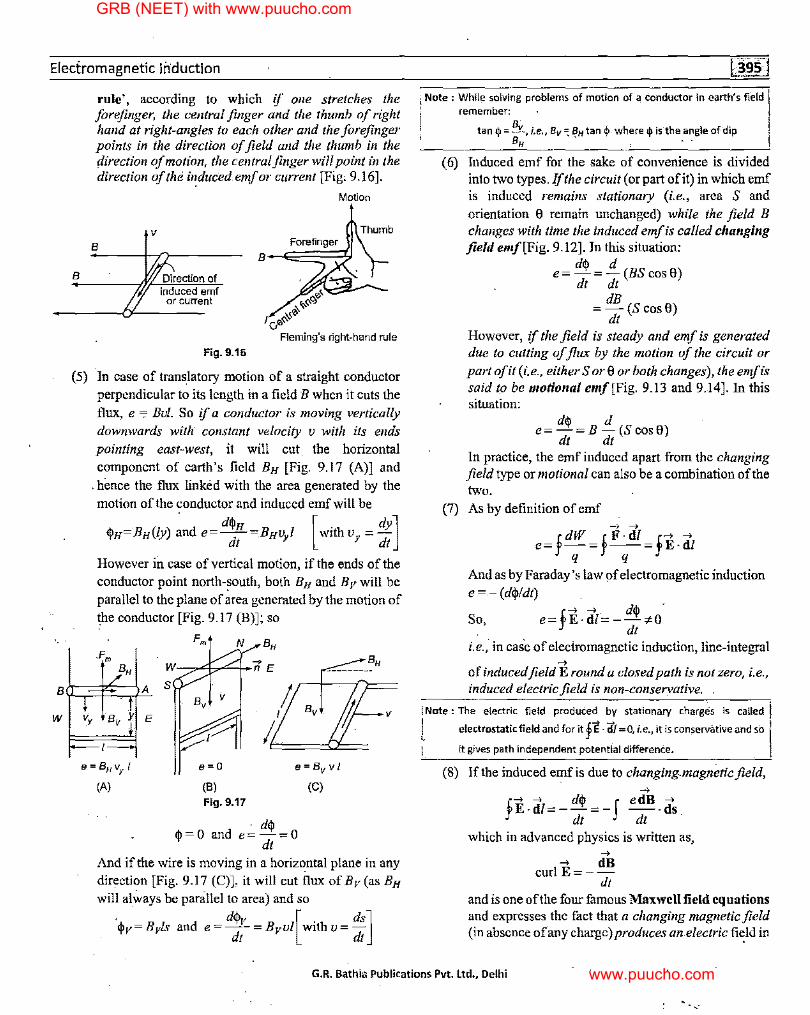
rule', according to which if one stretches the forefinger, the central finger and the thumb of right hand at right-angles to each other and the forefinger points in the direction of field and the thumb in the direction of motion, the central finger will point in the direction of the induced emf or current [Fig, 9.16].
V
B
Direction of induced emf
or current
Fig. 9.16
e< .,_.,<ll >I,~
cl-''
Motion
Fleming's right-hand rule
In case of translatory motion of a straight conductor perpendicular to its length in a field B when it cuts the
flux, e c, Bui. So if a conductor is moving vertically downwards with' constant velocity v with its ends pointing east-west, it will cut. the horizontal component of earth's field By [Fig. 9.17 (A)] and
. hence the flux linked with the area generated by the motion of the conductor and induced emf will be
~y='By(/y) and e= d$y =Byvyl [with vy = dy] dt dt
However in case of vertical motion, if the ends of the conductor point north-~outh, both By and Bv will be parallel to the plane of area generated by the motion of the conductor [Fig. 9.17 (B)]; so
Pm
A s
Fm N BH ... BH n E ---------
/; I Bv
/;_
e=O e = Bv v l
(8) Fig. 9.17
' d$ ~=O and e=-=0
dt
(C)
And if the wire is moving in a horizontal plane in any direction [Fig. 9.17 (C)], it will cut flux of Bv (as By will always be parallel to area) and so
·~v= Bvls and e = d~v = Bvvl[with v = ds] dt dt
Note : While solving _problems-of motion of a conductor in earth's field remember:
tan lfl = BV, i.e., Bv =~f!H tan ~ where q> is the angle of dip BH - ..
( 6) Induced emf for the sake of convenience is divided into two types. Jfthe circuit (or part ofit) in which emf is induced remains stationary (i.e., area S and orientation 0 remain unchanged) while the field B changes with time the induced emf is called changing field emf[Fig. 9.12]. In this situation:
d$ d e= -= - (BS cos 0)
dt dt dB
=-(Scos0) dt
However, if the field is steady and emf is generated due to cutting of flux by the motion of the circuit or part ofit (i.e., either Sor 0 or both changes), the emf is said to be motional emf[Fig. 9.13 and 9.14]. In this situation:
d$ d e= -= B - (S cos0)
dt dt In practice, the emf induced apart from the changing field type or motional can also be a combination of the two.
(7) As by definition of emf
And as by Faraday's law ofelectromagnetic induction e = -(d~ldt)
So, r-; -; d~ .
e=yE·dl=--,cO dt
i.e.,' in case of electromagnetic induction, line-integral -;
of induced field Eround a closed path is not zero, i.e., induced electric field is non-conservative.
i Note : The electric field produced by stationary charges is called j
electrostatic field and for it fE · di =0, i.e., it is conservative and sO II
it gives path independent potential difference.
(8) If the induced emf is due to changing.magnetic field, -;
rE,dl=-d~=-J edB·ds J dt dt .
which in advanced physics is written as, -;
-; dB curl E= --
dt and is one of the four famous Maxwell field equations and expresses the fact that a changing magnetic field (in absence ofany charge) produces an electric fi~ld in
G.R. Bathla Publications Pvt. Ltd., Delhi
GRB (NEET) with www.puucho.com
www.puucho.com
GRB Physics for Medical Entrance Exams (2nd Year Programme)
free space in the form of closed lines of force as shown in Fig. 9.18. So ifa charged particle is free to move in a circular path enclosing a changing magnetic field, the speed and hence kinetic energy of the charged particle will increase. This actually happens in betatron. This is also why a changing magnetic field can accelerate a charged particle at rest though a steady magnetic field can never.
(A) (B)
Fig. 9.18
i NOte : Here it is.worth\'.fo note that: · · I j '(i} In case of non-conse_rvative electric field: ·
l (a) The work done round a closed,.path is not zero. (b) Lines of
1 force are closed curves and can exist in free space even in I absence of any charge.
(ii) Inverse of the fact that a changing magnetic field prodl.lces an j electric field is also found to be true, i.e., a changing electric field. produces magnetic field and thi? fact iS expressed 1
mathematically by the relation,
'-' !e-d/=µ,Eo d,P, =µ0 1, r dt
where] d = Eo d~ and is called displacement current. · dt
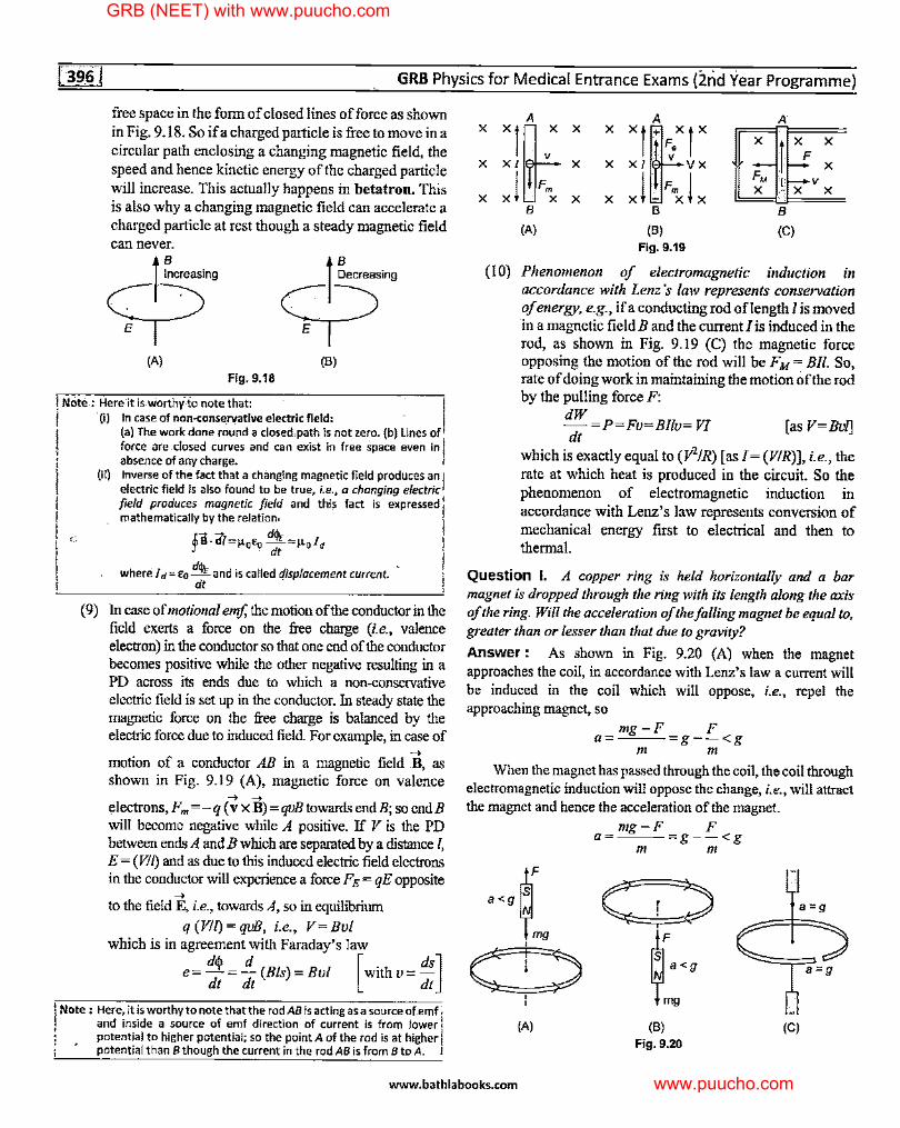
(9) In case of motional emf, the motion of the conductor in the field exerts a force on the free charge (i.e., valence electron) in the conductor so that one end of the conductor becomes positive while the other negative resulting in a PD across its ends due to which a non-conservative electric field is set up in the conductor. In steady state the magnetic force on the free charge is balanced by the electric force due to induced field. For example, in case of
-+ motion of a conductor AB in a magnetic field B, as shown in Fig. 9.19 (A), magnetic force on valence
-+ -+ electrons, Fm =-q (v x B) =qvB towards endB; so endB will become negative while A positive. If V is the PD between ends A and B which are separated by a distance I, E = (VI{) and as due to this induced electric field electrons in the conductor will experience a force FE= qE opposite
-+ to the field E, i.e., towards A, so in equilibrium
q (VI{)= qvB, i.e., V= Bvl which is in agreement with Faraday's law
e = d.p = _!i_ (Bis)= Bvl [with v = ds] dt dt dt
I Note : Here, it is worthy to note that the rod AB is acting as a source of.en'lf; and inside a source of emf direction of current is from lower j
1 potential to higher potential; So the point A of the rod is at higherj i • potential than B though the current in the rod AB is from B to A.
A A A X
"'t X X
"'f" X X X F
X XI X X XI VX X
xi Fmx X j -FmX ! X
FM I V X • X X
X X X B B B
(A) (B) (C) Fig. 9.19
(IO) Phenomenon of electromagnetic induction in accordance with Lenz 's law represents conservation of energy, e.g., if a conducting rod of length I is moved in a magnetic field B and the current I is induced in the rod, as shown in Fig. 9.19 (C) the magnetic force opposing the motion of the rod will be FM= BIi. So, rate of doing work in maintaining the motion of the rod by the pulling force F:
dW - =P=Fv=Bllv= VI [as V=Bvl] dt
which is exactly equal to (V2/R) [as I= (V/R)], i.e., the rate at which heat is produced in the circuit. So the phenomenon of electromagnetic induction in accordance with Lenz's law represents conversion of mechanical energy first to electrical and then to thermal.
Question I. A copper ring is held horizontally and a bar magnet is dropped through the ring with its length along the axis of the ring. Will the acceleration of the falling magnet be equal to, greater than or lesser than that due to gravity?
Answer : As shown in Fig. 9.20 (A) when the magnet approaches the coil, in accordance with Lenz's law a current will be induced in the coil which will oppose, i.e., repel the approaching magnet, so
mg-F a=~--
m
F g--<g
m
When the magnet has passed through the coil, the coil through electromagnetic induction will oppose the change, i.e., will attract the magnet and hence the acceleration of the magnet.
a<grs] 1mg
c:::, ' '
(A)
mg-F F a= g--<g
m m
(B)
Fig. 9.20
a=g
(C)
www.bathlabooks.com
GRB (NEET) with www.puucho.com
www.puucho.com
Electromagnetic lndu-ction
Note : lftfie.ringin the abqve problem has a slot, an emf (which is changing
field type}will be indu5ed in the ring b1,1t no current will fl_ow; so the
coil -can· no .mc;are oppose the approach of the magnet and th~\ magnet will fall through the ·ring with an acceleration a =.g. 1
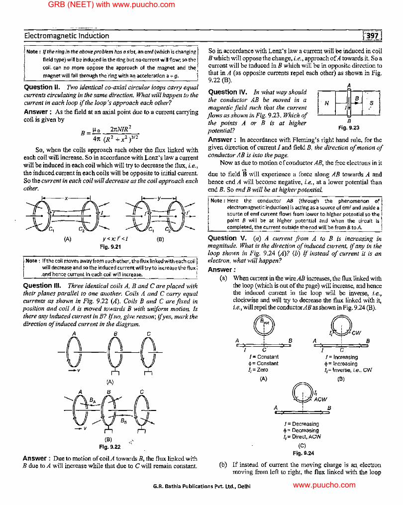
Question II. Two identical co-axial circular loops carry equal currents circulating in the same direction. What will happen to the current in each loop if the loop's approach each other?
Answer : As the field at an axial point due to a current carrying coil is given by
B = µo 2rcNIR2
4rc (R z + xz ),12
So, when the coils approach each other the flux linked with each coil will increase. So in accordance with Lenz's law a current will be induced in each coil which will try to decrease the flux, i.e., the induced current in each coils will be opposite to initial current. So the current in each coil will decrease as the coil approach each other.
~
x _..,,.,-
I J..___
c, c, --..._ (A) y<x;l'<J
Fig, 9.21 (8)
Note : lfthe coil moves away from ea~h other, the flux linked with each coil! will decrease and so the induced·current will try to increase the flux; .arJ.;l hence c~rrent in each coil will increase. !
Question Ill. Three identical coils A, B and Care placed with their planes parallel to one another. Coils A and C carry equal currents as shown in Fig. 9.22 (A). Coils B and C are fixed in position and coil A is moved towards B with uniform motion. Is there any induced current in B? Ifno, give reason; if yes, mark the direction of induced current in the diagram.
A B C
-G-0 G-(A)
A B C
-tr~~ (8)
Fig. 9.22
Answer: Due to motion of coil A towards B, the flux linked with B due to A will increase while that due to C will remain constant.
So in accordance with Lenz's law a current will be induced in coil Bwhich will oppose the change, i.e., approach of A towards it. So a current will be induced in B which will be in opposite direction to that in A (as opposite currents repel each other) as shown in Fig. 9.22 (B).
Question IV. In what way should the conductor AB be moved in a magnetic field such that the current flows as shown in Fig. 9.23. Which of the points A or B is at higher potential?
B Fig. 9.23
Answer : In accordance with Fleming's right hand rule, for the given direction of current I and field B, the direction of motion of conductor AB is into the page.
Now as due to motion of conductor AB, the free electrons in it -->
due to field B will experience a force along AB towards A and hence end A will become negative, i.e., at a lower potential than end B. So end B will be at higher potential.
I Note : Here th_e conductor AB {through the phenomenon of I electromagnetic induction) is acting as a source of emf and inside a f
I so~rce of e~f current ~ows from lo~e-r to higher p-otenti~-1-so_ the l pomt 8 will be .at higher potential and when the c1rcu1t is l completed, the current outside the-rod will-be from-8 to A. j
Question V. (a) A cun·ent from A to B is increasing in magnitude. What is the direction of induced current, if any in the loop shown in Fig. 9.24 (A)? (b) If instead of current it is an electron, what will happen?
Answer: (a) When current in the wire AB increases, the flux linked with
the loop ( which is out of the page) will increase, and hence the induced current in the loop will be inverse, .i.e., clockwise and will try to decrease the flux linked with it, i.e., will repel the conductor AB as shown in Fig. 9 .24 (B).
Q]) lQcw A 1 8 A
1
1 8
I C I= Constant 4>= Constant 11 = Zero
I C I= Increasing qi= Increasing 11= Inverse, i.e., CW
(A) (8)
o~cw A I B
I= Decreasing 4> = Decreasing 11 = Direct, ACW
(C)
Fig. 9.24
(b) If instead of current the moving charge is an electron moving from left to right, the flux linked with the loop
G.R. Bathla Publications Pvt. Ltd., Delhi
GRB (NEET) with www.puucho.com
www.puucho.com
GRB Physics for Medical Entrance Exams-(2nd Year Programme)
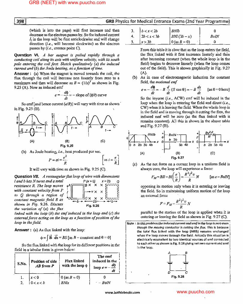
(which is into the page) will first increase ·and then decrease as the electron passes by. So the induced current I; in the loop will be first anticlockwise and will change direction (i.e., will become clockwise) as the electron passes by (i.e., crosses point C).
Question VI. A bar magnet is pulled rapidly through a conducting coil along its axis with uniform velocity, with its south pole entering the coil first. Sketch qualitatively (a) the induced current and (b) the Joule heating, as a function of time. Answer: (a) When the magnet is moved towards the coil, the flux through the coil will increase non linearly from zero to a maximum and then will decrease as B ~ (llx)3 as shown in Fig. 9.25 (A). Now as induced emf
. d$ e = - - = - slope of ( $It) curve
dt
So emf[and hence current (e/R)] will vary with time as shown· in Fig. 9.25 (B).
t $A
(A) (B)
Fig. 9.25 (C)
(b) As Joule heating, i.e., heat produced per sec.
P=ei= ~ [as i=f] It will vary with time as shown in Fig. 9.25 (C).
Question VII. A rectangular flat loop of wire with dimensions 1 and b has Nturns and a total P(x=O) x =2b Q
resistance R. The loop moves with constant velocity from P to Q through a region of constant magnetic field B as shown in Fig. 9.26. Discuss the variation of (a) the flux
tA I I r ~ X X ,r-------,, 11 11
I V X X 11 11 ,r ,, 11 ,,
ID C X X X ,~--------"J -b--2b-....,:.b-
Fig. 9.26
linked with the loop (b) the emf induced in the loop and (c) the external force acting on the loop as a function of position of the loop in the field.
Answer: (a) As flux linked with the loop:
$ = fB · ii:;= BS [ as B = constant and 0 = OJ
So the flux linked with the loop for its different positions in the field in a tabular form is given below:
S.No. Position of side
ABfromP
I. x<O 2. O<x<b
Flux linked with the loop $
O(asB=O)
BN/x
The emf induced in the
1oope=-d$ di
0
· -BvlN
3. 4. 5.
b<x<2b
2b<x<3b
x> 3b
BMb BM(3b-x)
O(asB=O)
0
BvlN
0
From this table it is clear that as the loop enters the field, the flux_ linked with it first increases linearly and then after becoming constant (when the whole loop is in the field) begins to decrease linearly (when the loop comes out of the field). This is shown graphically in Fig. 9.27 (A).
(b) As in case of electromagnetic induction for constant field, the motional emf
d$ d ds e=--=-B-(Scos0)=-B- [as0=0here]
dt dt dt
So the inyerse (i.e., ACW) emf will be induced in the loop when the loop is entering the field and direct (i.e.,. CW) when it is leaving the field. When the whole loop is in the field and is moving through it cutting the flux, the induced emf will be zero (as the flux linked with it remains constant). All this is shown in the above table and Fig. 9.27 (B). ·
Ob2b3b4b
(A)
3b 4b
(B)
Fig. 9.27
b2b3b4b
(C)
( c) As the net force on a current loop in a uniform field is always zero, the loop will experience a force:
FM=Bll=Bt(f) = B2
~
2
v N [ase=BvlN]
opposing its motion only when it is entering or leaving the field. So in maintaining uniform motion of the loop an external force
B 212 v F=FM=--N
R parallel to the motion of the loop is applied when it is entering or leaving the field as shown in Fig. 9.27 (C).
II Note : In this problem the induced current and emf in the loop is zero even 1
though the moving conductor is cutting the flux. This is because , the total flux linked with .the loop (NBIP) remains unchanged
when the loop moves through-t:ie field. Actually this situation is electrically equivalent to two identical sources of emf connected to each other as shown in Fig. 9.28 giving ne_t zero current and emf in the'loop:
A B
r--i T -T D C
Fig. 9.28
www.bathlabooks.com
GRB (NEET) with www.puucho.com
www.puucho.com
Electromagnetic Induction
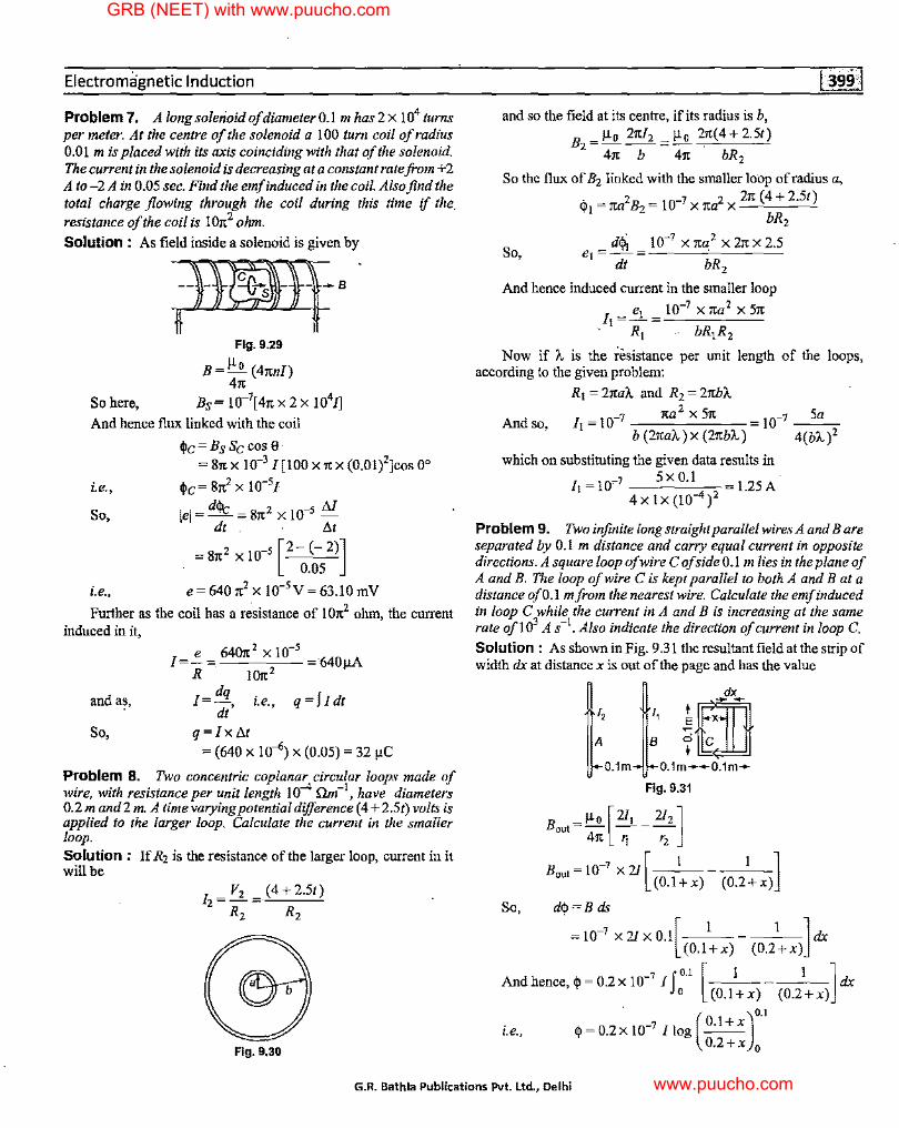
Problem 7. A longsoletioid of diameter0.I m has 2 x 10⁴ turns per meter. At the centre of the solenoid a 100 turn coil of radius 0.0 I m is placed with its axis coinciding with that of the solenoid. The current in the solenoid is decreasing at a constant rate from +2 A to-2 A in 0.05 sec. Find the emf induced in the coil. Also find the total charge flowing through the coil during this time if the_ resistance of the coil is 107t2 ohm.
Solution : As field inside a solenoid is given by
=)W-Ifs * t Fig. 9.29
B=µ 0 (4itnl) 4it
So here, Bs = 10-7[ 4it x 2 x 1041]
And hence flux linked with the coil
<Jlc= Bs Sc cos 0 = 81t x 10-3 I [100 x it x (0.01)2Jcos 0°
i.e., <Jlc=8it2 x 10-5[
So, lei= dcJlc = 8it 2 x !0-5 M dt . ' !J.t
= Sitz X l0-5 [2- (- 2)] 0.05
i.e., e=640it2x 10-5V=63.!0mV
Further as the coil has a r~sistance of I 0it2 ohm, the current induced in it,
J=.:..= 6407t2 X 10-5 640µA R !07t2
and a~, I=dq . q=fldt dt' i.e.,
So, q=lx!J.t
= (640 X 10-6) X (0.05) = 32 µC
Problem 8. Two concentric coplanar circular loops made of wire, with resistance per unit length 10-4 nn,-l, have diameters 0.2 m and2 m. A time varying potential difference (4+ 2.St) volts is applied to the larger loop. Calculate the current in the sma/ler loop. Solution : If R2 is the resistance of the larger loop, current in it will be
]z=V2 =(4+2.St)
R2 R2
Fig. 9,30
and so the field at its centre, if its radius is b, Bz = µ 0 27tl2 = ):Q_ 2it(4 + 2.St)
4it b 4it bR2
So the flux of B2 linked with the smaller loop ofradius a, .,, 2B io-7 2 2it (4 + 2.St) 'f1=1ta 2= X1ta x-~--~
bR2
d<j\ 10-? X ita 2 X 2it X 2.5 So, e1 =-= -----~----
dt bR1
And hence induced current in the smaller loop
Ji =..:l...= 10-7
Xita2
X51t ' R1 bR,R2
Now if A is the resistance per unit length of the loops, according to the given problem:
R1 = 2itaA and R2 = 2itb1',
And so, Ji = 10-7 ita 2 X Sit b (2ita1',) x (2itbA)
10_1 Sa
4(bA )2
which on substituting the given data results in
/i=I0-1 SxO.l 1.25A 4 x Ix (10-4)2
Problem 9. Two infinite long straight para/lei wires A and Bare separated by 0.1 m distance and carry equal current in opposite directions. A square loop of wire C of side 0.1 m lies in the plane of A and B. The loop of wire C is kept para/lei to both A and B at a distance of0. l mfrom the nearest wire. Calculate the emf induced in loop C while the current in A and B is increasing at the same rate of 103 A s-1
• Also indicate the direction of current in loop C. Solution : As shown in Fig. 9.3 I the resultant field at the strip of width dx at distance xis out of the page and has the value
t,. dx
1, it:ID B
o.1m---o.1m--
Fig. 9.31
Bout=µ" [211 - 212] 41t 1i r2
Bout= I 0-7 x 21 [ I (O.l+x)
So, dcp=Bds
=10-1 x21xo.1[ 1
-1 ]c1x
(0.l+x) (0,2+x)
And hence, cp = 0.2 x 10- I --- --- dx 7 J 0.1 [ I I ] o (O.l+x) (0.2+x)
i.e., q,=0.2x10⁻⁷ Ilog O.l+x . ( )0.1
0.2+x 0
G.R. Bathla Publications Pvt. Ltd., Delhi
GRB (NEET) with www.puucho.com
www.puucho.com
·-~-- GRB Physks for Medical Entrance Exams (2nd Year Progra.mme)
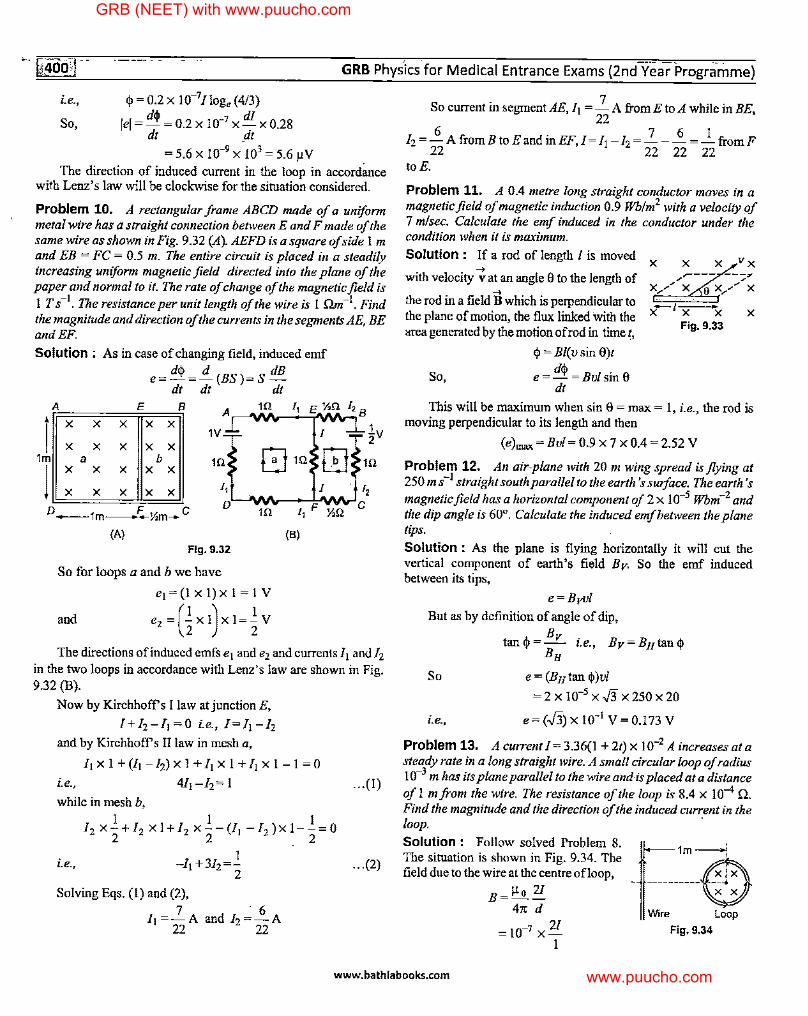
i.e., <j, = 0.2 X 10⁻⁷Jloge (4/3)
So, lei = d<j, = 0.2 X 10⁻⁷ X dJ X 0.28 dt dt
=5.6 X 10-9 X 103 = 5.6 µV
The direction of induced current in the loop in accordance with Lenz's law will be clockwise for the situation considered.
Problem 10. A rectangular frame ABCD made of a uniform metal wire has a straight connection between E and F made of the same wire as shown in Fig. 9.32 (A}. AEFD is a square of side Im and EB = FC = 0.5 m. The entire circuit is placed in a steadily increasing uniform magnetic field directed into the plane of the paper and normal to it. The rate of change of the magnetic field is 1 T s-1
• The resistance per unit length of the wire is I nm-I. Find the magnitude and direction of the currents in the segments AE, BE and EF.
Solution : As in case of changing field, induced emf
e= d<j, =i._ (BS)=S dB dt dt dt
A E B A 1Q 1,
i X X X X X 1V
X X X X X EJ 1Q 1m a b 1Q
l X X X X X
X X X X X 1,
0-1m_F--½m--c D
1Q
(A) Fig. 9.32
So for loops a and b we have
e1 = (I x I) x 1 = I V
and e,=Gx1)x1=1V
(B)
I
½.Q
12 B
1v 2
1Q
1,
C
The directions of induced emfs e1 and e2 and currentsfi and/2 in the two loops in accordance with Lenz's law are shown in Fig. 9.32 (B).
Now by Kirchhoff's I law atjunctionE,
I+I,-11 =O i.e., l=fi-I, and by Kirchhoff's II law in mesh a,
/1 X I + (/1 - f,) X 1 + /1 X 1 + /1 X 1 - 1 = 0
i.e., 4/i-I,=l
while in mesh b, 1 1 I
12 x-+12 xl+/2 x--(/1 -/2 }xl--=0 2 2 _ 2
1 -/1 +31,=-
2 i.e.,
Solving Eqs. (!) and (2), 7 - 6
Ii =-A and I,=-A 22 22
... (I)
... (2)
So current in segment AE, Ii = 2 A from E to A while in BE, 22
6 . 7 6 I I,=-AfromBtoEandmEF /=/1-I,=---=-fromF
22 ' 22 22 22 toE.
Problem 11. A 0.4 metre long straight conductor moves in a magnetic field of magnetic induction 0.9 Wb!m2 with a velocity of 7 mlsec. Calculate the emf induced in the conductor under the condition when it is maximum.
Solution : If a rod of length I is moved x X X
with velocity-; at an angle 8 to the length of /~--- -:_7 X.,..,.. X 9 x,......- X _,
the rod in a field B which is perpendicular to the plane of motion, the flux linked with the area generated by the motion of rod in time t,
So,
q, = Bl(u sin 8)1
e= d<j, =Bu/sine dt
x---1,r----x Fig. 9.33
X
This will be maximum when sin 8 =max= I, i.e., the rod is moving perpendicular to its length and then
(e)max =Bu/= 0.9 X 7 X 0.4 = 2.52 V
Problem 12. An air-plane with 20 m wing spread is flying at 250 m s-1 straight south parallel to the earth's suiface. The earth's magnetic field has a horizontal component of 2 x 10⁻⁵ Wbm-2 and the dip angle is 60°. Calculate the induced emf between the plane tips.
Solution : As the plane is flying horizontally it will cut the vertical component of earth's field Bv- So the emf induced between its tips,
e=Bvvl
But as by definition of angle of dip,
tan<j,= Bv i.e., Bv=Bntan<j, BH
So e = (Bntan <j,)u/
= 2 X 10⁻⁵ X -J3 X 250 X 20
i.e., e= (J'i) x 10-1 V= 0.173 V
Problem 13. A current I= 3.36(1 + 2t) x 10-2 A increases at a steady rate in a long straight wire. A small circular loop of radius 10-3 m has its plane parallel to the wire and is placed ata distance of I m from the wire. The resistance of the loop is 8.4 x I o-4 n. Find the magnitude and the direction of the induced current in the loop. ·
Solution : Follow solved Problem 8. The situation is shown in Fig. 9.34. The field due to the wire at the centre ofloop,
B=~2/ 41t d
= 10-1 X 2/ I
f--1m -.J
Wire Loop
Fig, 9.34
www.bathlabooks.com
GRB (NEET) with www.puucho.com
www.puucho.com
Electromagnetic Induction
So the flux linked with the loop wire
4'=BS=Bx1tl
= 10-7 X 2/X 'It X (10-3)2 So emf induced in the loop due to change of current
I I_ dqi _ 2 10-13 dl e---1CX -dt dt
But as here
l = 3.36(1 + 21) X 10-2
So d[ = 6.72 X 10⁻² A/s dt
And hence e=21tx 10-13 x 6.72 x 10-2
= 13.441' X 10-15 V
And so the induced current in the loop
e . 13.441' X 10-15 I=------ 167tx!0-12 A
R 8.4 X 10⁻⁴
As due to increase in current in the wire the flux linked with the loop will increase, so in accordance with Lenz's law the direction of current induced in the loop will be inverse of that in wire, i.e., anticlockwise.
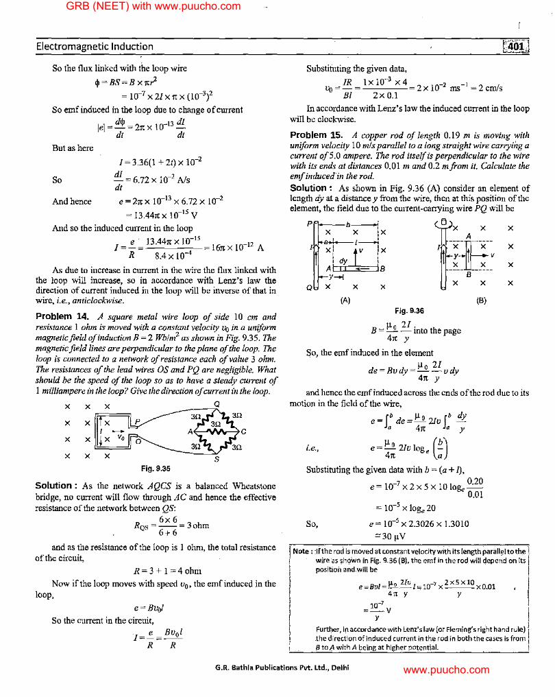
Problem 14. A square metal wire loop of side 10 cm and resistance 1 ohm is moved with a constant velocity Vo in a uniform magnetic field ofinductionB =2 Wb!m2 as shown in Fig. 9.35. The magnetic field lines are perpendicular to the plane of the loop. The loop is connected to a network of resistance each of value 3 ohm. The resistances of the lead wires OS and PQ are negligible. What should be the speed of the loop so as to have a steady current of I milliampere in the loop? Give the direction of current in the loop.
X X X Q
X X X
I -X X X Vo
X X X
Fig. 9.35
Solution : As the network AQCS is a balanced Wheatstone bridge, no current will flow through AC and hence the effective resistance of the network bet.veen QS:
6x6 RQs=--=3ohm
6+ 6
and as the resistance of the loop is I ohm, the total resistance of the circuit,
R=3+1=4ohm
Now if the loop moves with speed u0, the emf induced in the loop,
e=Bu,}
So the current in the circuit,
I=!_= Bu0l R R
Substituting the given data,
IR 1x10-3 x4 LJo=-=---- 2xl0-2 ms-1 =2cm/s
Bl 2x0.l
In accordance with Lenz' s law the induced current in the loop will be clockwise.
Problem 15. A copper rod of length 0.19 m is moving with uniform velocity 10 mis parallel to a long straight wire carrying a current of5.0 ampere. The rod itself is perpendicular to the wire with its ends at distances 0.01 m and 0.2 mfrom it. Calculate the emf induced in the rod.
Solution : As shown in Fig. 9.36 (A) consider an element of length dy at a distance y from the wire, then at this position of the element, the field due to the current-carrying wire PQ will be
P~bx4x
/~:r-~;--J X
~ _IJ-X X
ltf;-I dy I
A B Y-+I
Q X X X u-x X
(A) Fig. 9.36
B = !:1:..2. 21
into the page 41' y
So, the emf induced in the element
µo 2l de=Budy=--udy
41' y
(B)
X
X
X
X
and hence the emf induced across the ends of the rod due to its motion in the field of the wire,
e =fb de= µo 2/v fb dy a 41t a y
i.e., e = µo 2/v log, (!!.) 41t a
Substituting the given data with b = (a+ l),
So,
e= 10-7 x2 x 5 x 10 Jog, 0
·20
0.01
= 10-5 X Jog, 20
e = 10-5 X 2.3026 X 1.3010
"'30µV
Note : :If the rod is nioved at constant velocity with its length parallel to the l wire as sh9Wn in Fig. 9:36 (B), the emf in the·rod will depend on its positioil and.will be
e=Bvl =~ Uv l=lo-1 x zxsxio x0.01' 41t y y
10-7 =-V
y
Further, In accordance.with Lenz's law (or Fleming's right hand rule) the direction of induced current in the rod in both,the cases is from B to A with A being at higher potential.
G.R. Bathla Publications Pvt. Ltd., Delhi
GRB (NEET) with www.puucho.com
www.puucho.com
GRB Physics for Medical Entrance Exams (2nd Year Programme)
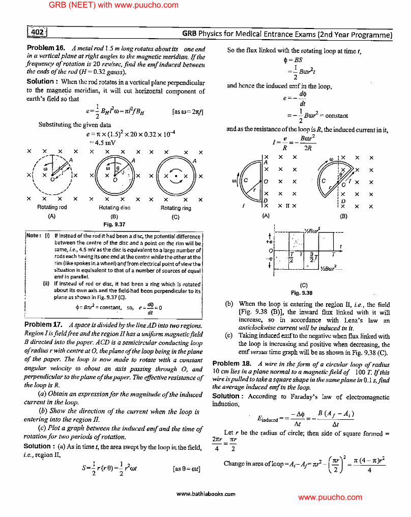
Problem 16. A metal rod 1.5 m long rotates about its one end in a vertical plane at right angles to the magnetic meridian. If the frequency of rotation is 20 rev/sec, find the emf induced between the ends of the rod (H = 0.32 gauss).
Solution : When the rod rotates in a vertical plane perpendicular to the magnetic meridian, it will cut horizontal component of earth's field so that
[ as co= Zit.I]
Substituting the given data
e = it X (1.5)2 X 20 X 0.32 X I 0-4 =4.5mV
X X X X
/ ' ' ...o, /~:-,, A
' 0) ' ·t?'/\ x' x / 1 'x
\ 0 J
X
\ I \ I ,..... .,,.,, ----X X
Rotating rod
(A)
X X X X
Rotating disc
(B) Fig. 9.37
X X X X X Rotating ring
(C)
Note: (i) If instead of the r-od it had been a disc, the potential-difference between the.centre of the disc and a point on the rim will be same, i.e_., 4.5 mV as the disc is equivalent to a large number of rods each havirig its one end at the centre while the other at the rirri (like spokes in a wheel) an~ frorri electrical point of view the situation is.equivalent to that of a number of sources of equa! ~mf In parallel.
(ii) If instead of rod or disc, it had 'been a ring which is .rotated about its own axis and the field,had been perpendicular to its plane as shown in Fig. 9.37 (C).
$ = Bnr2 = constant so e = d$ = o ', , dt
Problem 17. A space is divided by the line AD into two regions. Region I is field free and the region II has a uniform magnetic field B directed into the paper. ACD is a semicircular conducting loop of radius r with centre at 0, the plane of the loop being in the plane of the paper. The loop is now made to rotate with a constant
angular velocity co about an axis passing through 0, and perpendicular to the plane of the paper. The effective resistance of the loop is R.
(a) Obtain an expression for the magnitude of the induced current in the loop.
(b) Show the direction of the current when the loop is entering into the region II.
(c) Plot a graph between the induced emf and the time of rotation for two periods of rotation.
Solution : (a) As in time I, the area swept by the loop in the field, i.e., re~ion II,
I I 2 S=- r(r8)=- root
2 2 [as e = cot]
So the flux linked with the rotating loop at time t,
lj,=BS
=.!_Bro?t 2
and hence the induced emf in the loop, dip
e=--dt
= - .!. Bro? = constant 2
and as the resistance of the loop is R, the induced current in it,
-i~ I
I=!!_=_ Bror2
R 2R X X X A X X X
0 X X
X X X D X X II X
(A) (B)
:-~~-,½Bror~ ---t ' +e
o1--c-trc.--sclrh3c+-~r,... -• ,. 2 2T ½ !--'-'--'--~ ½Bml--
(C) Fig. 9.38
X
X
(b) When the loop is entering the region II, i.e., the field [Fig. 9.38 (B)], the inward flux linked with it will increase, so in accordance with Lenz's law an anticlockwise current will be induced in it.
(c) Taking induced emf to the negative when flux linked with the loop is increasing and positive when decreasing, the emf versus time graph will be as shown in Fig. 9.38 (C).
Problem 18. A wire in the form of a circular loop of radius 10 cm lies in a plane normal to a magnetic field of 100 T. If this wire is pulled to take a square shape in the same plane in 0.1 s,find the average induced emf in the loop.
Solution : According to Faraday's law of electromagnetic induction,
-1'4' B (A1 -A;) Einduced = = --= - -~---
M Llt Let r be the radius of circle; then side of square formed =
21tr xr -=-
4 2
Change in area ofloop = A;-A1= it?-( 1;) 2 it (4- it)r2
4
www.bathlabooks.com
GRB (NEET) with www.puucho.com
www.puucho.com
Electromagnetic Induction
Hence average emf induced
1t(4-1t)r2 B 4 t
1t (4 - it) X (0.1)2 X 100 = -------''--------''--'----'------ 6.75 volt
4x0.I
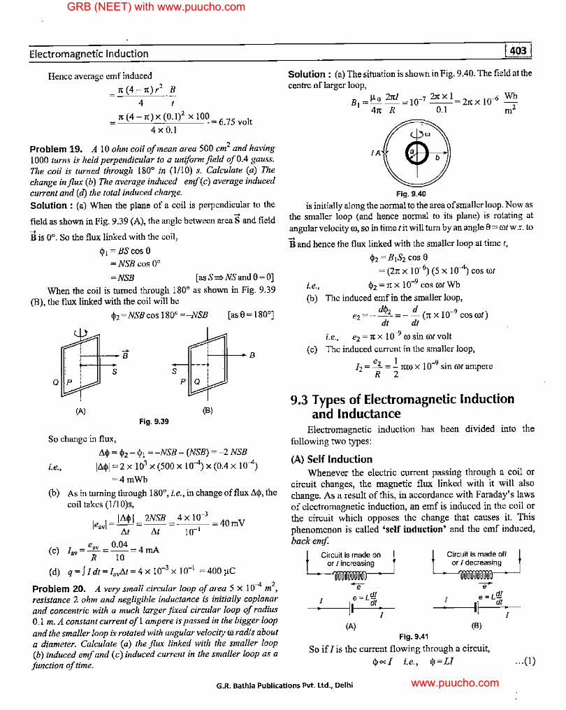
Problem 19. A 10 ohm coil of mean area 500 cm2 and having 1000 turns is held perpendicular to a uniform field of0.4 gauss. The coil is turned through 180° in (1/10) s. Calculate (a) The change influx (b) The average induced emf(c) average induced current and (d) the total induced charge. Solution : (a) When the plane of a coil is perpendicular to the ..., field as shown in Fig. 9.39 (A), the angle between area S and field ..., B is 0°. So the flux linked with the coil,
<j, 1=BScos0
=NSB cos 0°
=NSB [asS=>NSand0=0]
When the coil is turned through 180° as shown in Fig. 9.39 (B), the flux linked with the coil will be
<1>2=NSBcosl80°=-NSB [as0=180°]
(A) Fig. 9.39
So change in flux,
s
(B)
A<j, = <!>2 - <!>1 = -NSB - (NSB) = -2 NSB
i.e., IA<l>I = 2 x 103 x (500 x 10-4) x (0.4 x 10-4)
=4mWb
(b) As in turning through 180°, i.e., in change offluxAq>, the coil takes (1/I0)s,
le,vl = IA<l>I = 2NSB = 4 X 10⁻³ 40rnV At M 10-1
(c) 1 = e,v = 0.04 = 4 rnA av R IO
(d) q =f I dt=I,vAt=4 X 10-3 X 10-l =400 µC
Problem 20. A very small circular loop of area 5 x 10⁻⁴ m2,
resistance 2 ohm and negligible inductance is initially coplanar and concentric with a much larger fzxed circular loop of radius 0.1 m. A constant current of 1 ampere is passed in the bigger loop and the smaller loop is rotated with angular velocity co rad/s about a diameter. Calculate (a) the flux linked with the smaller loop (b) induced emf and (c) induced current in the smaller loop as a function of time.
Solution : (a) The situation is shown in Fig. 9.40. The field at the centre of larger loop,
B1 = µo 2it/ = 10-7 2it XI= 2it X 10--6 Wb 41t R 0.1 m2
IA
Fig. 9.40
is initially along the normal to the area of smaller loop. Now as the smaller loop ( and hence normal to its plane) is rotating at angnlarvelocity co, so in time lit will turn by an angle 0 = cotw.r. to ..., B and hence the flux linked with the smaller loop at time t,
<!>2 = B1S2 cos 0
= (21t X 10--6) ( 5 X I 0-4) cos rot
i.e., <!>2 = 1t X 10-9 COS rot Wb
(b) The induced emf in the smaller loop, d<I>, d -9
e2=--=--(1tx!0 COSCO/) dt dt
i.e., e2 = 1t x 10-9 co sin rot volt
(c) The induced current iu the smaller loop,
e2 1 -9· Ii= - = - itro x 10 sm rot ampere R 2
9.3 Types of Electromagnetic Induction and Inductance
Electromagnetic induction has been divided into the following two types:
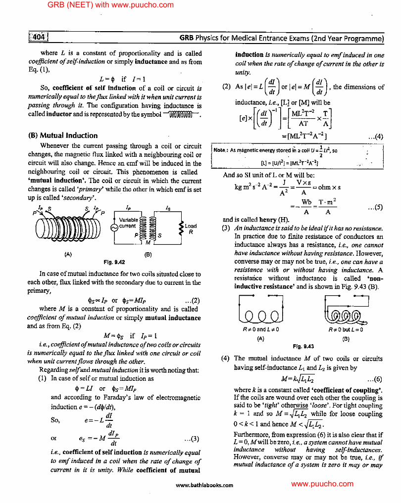
(A) Self Induction Whenever the electric current passing through a coil or
circuit changes, the magnetic flux linked with it will also change. As a result of this, in accordance with Faraday's laws of electromagnetic induction, an emf is induced in the coil or the circuit which opposes the change that causes it. This phenomenon is called 'self induction' and the emf induced, back emf
Circuit is mad~_on 1 or J increasi~
.... I e = L,g_
I dt I
(A) Fig. 9.41
Circuit is mad~ ~ff ! or/ decreasi~
7 I e = L,g_
I\ dt I
(B)
So if/ is the current flowing through a circuit,
<j,=l i.e., <j,=LI ... (I)
G.R. Bathla Publications Pvt. Ltd., Delhi
GRB (NEET) with www.puucho.com
www.puucho.com
GRB Physics for Medical Entrance Exams (2nd Year Programme)
where L is a constant of proportionality and is called coefficient of self-induction or simply inductance and as from Eq. (1),
L=(j) if I= 1 So, coefficient of self indnction of a coil or circuit is
numerically equal to the flux linked with it when unit current is passing through it. The configuration having inductance is called inductor and is represented by the symbol ~.
(B) Mutual Induction Whenever the current passing through a coil or circuit
changes, the magnetic flux linked with a neighbouring coil or circuit will also change. Hence an emf will be induced in the neighbouring coil or circuit. This phenomenon is called 'mutual induction'. The coil or circuit in which the current changes is called 'primary' while. the other in which emf is set up is called 'secondary'.
Variable
p
(A) Fig. 9.42
Dis Load
R
M
(B)
In case of mutual inductance for two coils situated close to each other, flux linked with the secondary due to current in the primary,
<l>s=lp or <!>s=Mlp ... (2) where M is a constant of proportionality and is called
coefficient of mutual induction or simply mutual inductance and as from Eq. (2)
M=<ps if lp= 1 i.e., coefficient of mutual inductance of two coils or circuits
is numerically equal to the flux linked with one circuit or coil when unit current flows through the other.
Regarding self and mutual induction it is worth noting that: {I) In case of selfor mutual induction as
(j)=LI or <!>s=Mlp and according to Faraday's law of electromagnetic
induction e = - ( d<pl dt), dl
So, e=-L-dt dlp
m ¾=-M- ... ~) dt
i.e., coefficient of self induction is numerically equal to emf induced in a coil when the rate of change of current in it is unity. While coefficient of mutual
induction is numerically equal to emf induced in one coil when the rate of change of current in the other is unity.
(2) As I e[ = L (dl) or I e[ = M (dl), the dimensions of dt . dt
inductance, i.e., [L] or [M] will be
[e]x[(:r']=[~;-2
X :]
= [Mr:T-2 A -2]
Note: As magne~ic energy stored irl··a.~oll U=!t/2, so . 2
[L] = [U/12] = [ML2r 2A-~]
And so SI unit ofL or M will be:
kgm2 s-2 A-2 =_!._= Vxs =ohmx s A 2 A
Wb T·m 2
=--=--A A
and is called henry (H).
... (4)
... (5)
(3) An inductance is said to be ideal ifit has no resistance. In practice. due to finite resistance of conductors an inductance always has a resistance, i.e., one cannot have inductance without having resistance. However, converse may or may not be true, i.e., one can have a resistance with or without having inductance. A resistance without inductance is called 'noninductive resistance' and is shown in Fig. 9.43 {B).
R,sOandL•O
(A) Fig. 9.43
Ra'Obu!L=O
(B)
( 4) The mutual inductance M of two coils or circuits having self-inductance L1 and Li is given by
M=k..[i;i; ... (6)
where k is a constant called 'coefficient of coupling'. If the coils are wound over each other the coupling is said to be 'tight' otherwise 'loose'. For tight coupling k = I and so M =~Li L2 while for loose coupling
0 < k< 1 and hence M <~½½· Furthermore, from expression (6) it is also clear that if L = 0, M will be zero, i.e., a system cannot have mutual inductance without having self-inductances. However, converse may or may not be true, i.e., if mutual inductance of a system is zero it may or may
www.bathlabooks.com
GRB (NEET) with www.puucho.com
www.puucho.com
Electromagnetic Induction
not have self-inductances as M = 0 can be satisfied either by setting k = 0 or L = 0.
(5) Self inductance in some cases of interest (a) Selfinductanceofacoil: AsforacoilofradiusR
having N turns, field at the centre of the coil,'
B=µ 0 2rcNI 4rc R
So flux linked with the coil due to its own current,
(J>=BS=µo (2rcNI)(rcR 2 N)=µo (2rc 2 N 2R)I
4rc R 4rc
But as by definition, (Ji = LI
So, Lc=µ 0 (2rc 2 N 2R)=Lµ 0rcN 2R ... (7) 4rc 2
(b) Self inductance of a solenoid : In case of a solenoid having n turns per unit length,
B=~; (4rcnl)=µ 0nl =µ 0 (~)r(as n= ~)
and so if the cross-sectional area of solenoid is S.
(J>=B(NS)=µo ( ~)rx(NS)=µo ~2
SI
But as by definition, (Ji = LI
So, Ls=µ 0 (~
2
)s=µ 0n2S1 ... (8)
(6) Energy stored in a coil Wheu current in a coil is changing, due to opposition by the
coil through its self inductance L, work done in time dt,
dW=Pdt=eldt=Lldl [ase=L ~~] So work done in establishing a current Jin the coil
W= r' LI dI =Luz lo 2
This work is stored as 'magnetic potential energy' UM which is not localised but is distributed in the field associated with the current-carrying coil, i.e.,
I UM=W=-Ll2
2 ... (9)
From Eq. (9), it is clearthatL= 2Wifl =I.So coefficient of self induction of a coil is also numerically equal to twice the work required to establish a unit current in the coil.
!.Note : .As for a solenoid L = 1,1on2St, magne.tic energy per unit volume;
'J .!.uz u 2- '1.22 uM=--=-=-µ 0nJ
Volume IS 2
and as fcira:solenoid, 8 = 1,1onl, 2 •:,
UM=!µ, x(!...) ~!£ 2 µ, 2 µ,
..• (10)
This expreSSion is general and Is Called 'eriergydensity''Of magnetic
fle\d·and'is a·magnetic a_nalogue ofui = !. qJE2• . . 2
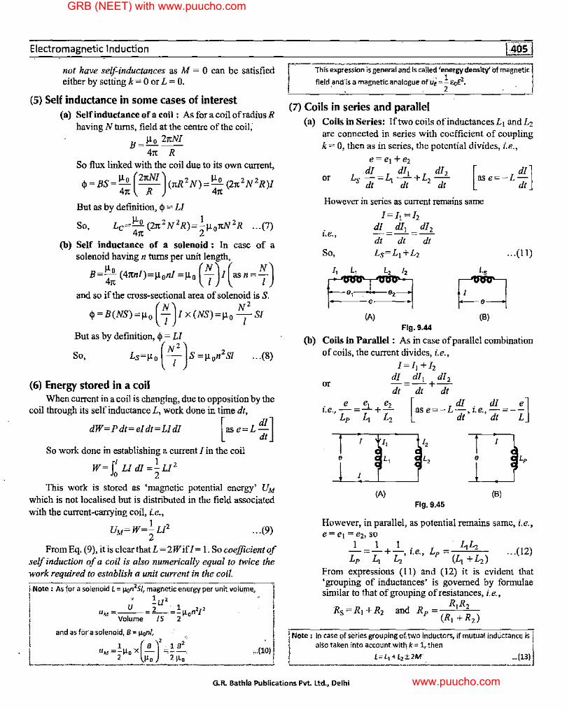
(7) Coils in series and parallel (a) Coils in Series: If two coils ofinductancesL1 andL2
are connected in series with coefficient of coupling k= O; then as in series, the potential divides, i.e.,
(b)
or
However in series as current remains same
i.e.,
So,
[=Ji =[z dl dl1 dl2 =-=-dt dt dt
(B)
Flg.9.44
... (11)
Coils in Parallel : As in case of parallel combination of coils, the current divides, i.e.,
I=I, +[z dl dl1 dl2 or -=-+-dt dt dt
i.e.,;= z + ;: [ase=-L !,i.e, ! =-z]
I
e
I
(A) (B) Fig. 9.45
However, in parallel, as potential remains same, i.e., e = e1 = e2, so
- 1-=_L_+-1 i.e. L =. LiLz (12) Lp ½ Lz' ' P (Li +Lz) ...
From expressions (11) and (12) it is evident that 'grouping of inductances' is governed by formulae similar to that of grouping ofresistances, i.e.,
RR Rs=R,+R2 and Rp- 1 2
(R1 + R2 )
f Note : In case-of series grouping of two inductors, if mutua"I indl.Jctance is alSo taken into account.with k-= l, . .then
L=L1+l2±2M', ~ ... (13)
G.R. Bathla Publications Pvt. Ltd., Delhi
GRB (NEET) with www.puucho.com
www.puucho.com
r as·shown in Fig. 9.46.
L, M Lz
r::::7 Current.In the two coils
is in same direction
(A)
Fig. 9.46
GRB Physics for Medical Entrance Exams (2nd Year Programme)
L=L, +Lz'-2M
Current in-the two coils is in opposite direction
(B)
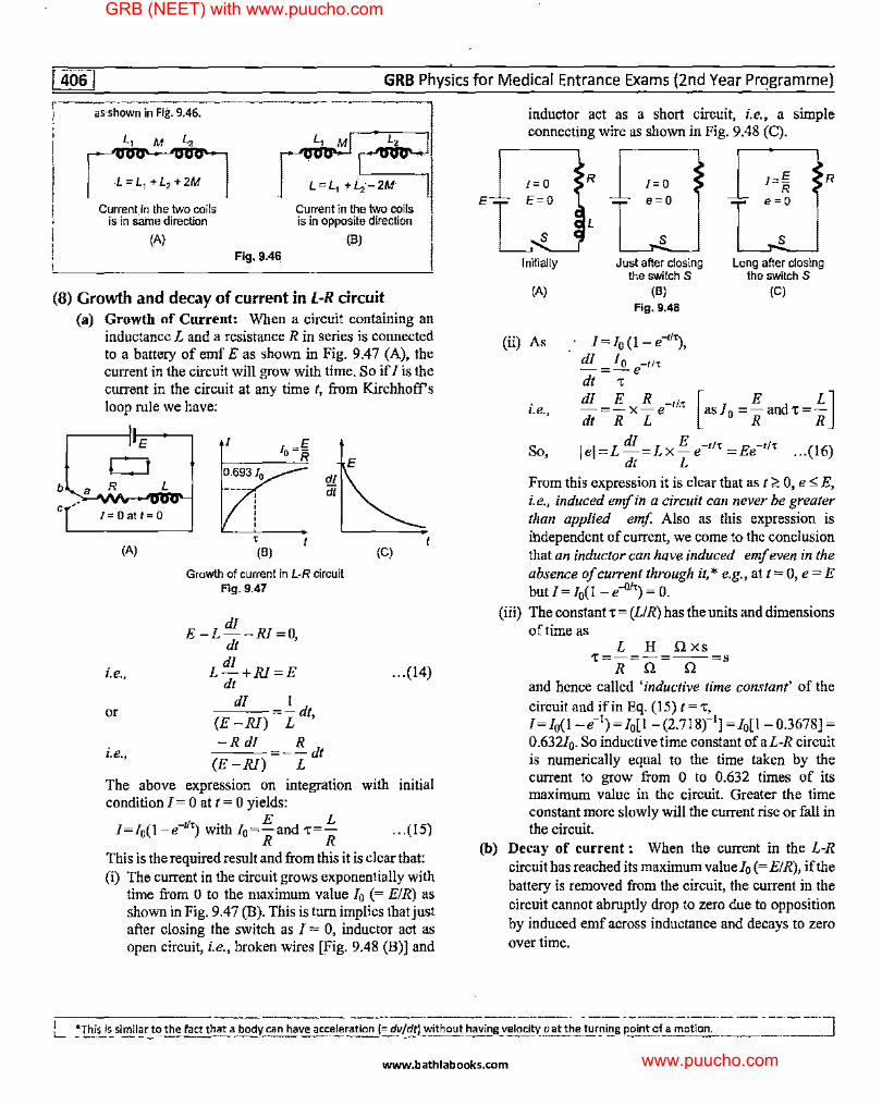
inductor act as a short circuit, i.e., a simple connecting wire as shown in Fig. 9.48 (C).
R I= 0 I=g R R
e=O e=O
L
s s Just after closing Long after closing
the switch S the switch S
(8) Growth and decay of current in L-R circuit (A) (B) (C)
Fig. 9.48
b
C
(a) Growth of Current: When a circuit containing an inductance L and a resistance R in series is connected to a battery of emf E as shown in Fig. 9.47 (A), the current in the circuit will grow with time. So if I is the current in the circuit at any time t, from Kirchhoff's loop rule we have:
E
~ R L
I=Oatt=O
(A)
i.e.,
or
i.e .•
I
0.69310
' (B)
di di
Growth of current in L-R circuit Fig. 9.47
dl E-L--Rl=0 dt ,
L dl +RI=E dt
dl I L dt, (E-RI)
-Rd! =-Rdt (E-RI) L
E
(C)
... (14)
The above expression on integration with initial condition I= 0 at t = 0 yields:
-u, . E L ) l=/0(1-e ) with / 0 =-and -r=- ... (15 R R
This is the required result and from this it is clear that: (i) The current in the circuit grows exponentially with
time from Oto the maximum value /0 (= EIR) as shown in Fig. 9.47 (B). This is tum implies that just after closing the switch as / = 0, inductor act as open circuit, i.e., broken wires [Fig. 9.48 (B)] and
(b)
(ii) As
i.e.,
So,
From this expression it is clear that as t ~ 0, e ,,; E, i.e., induced emf in a circuit can never be greater than applied emf Also as this expression is independent of current, we come to the conclusion that an inductor can have induced emf even in the absence of current through it,* e.g., at t = 0, e = E but/= / 0(1 - e--01') = 0.
(iii) The constant't = (LIR) has the units and dimensions of time as
L H Qxs 't=-=-=--=s
R Q Q
and hence called 'inductive time constant' of the
circuit and ifin Eq. (15) t = 't, l=lo(l -e-1
) = lo[I -(2.718r1J =Io[! -0.3678] = 0.632/0• So inductive time constant of aL-R circuit is numerically equal to the time taken by the current to grow from O to 0.632 times of its maximum value in the circuit. Greater the time constant more slowly will the current rise or fall in the circuit.
Decay of current : When the current in the L-R circuit has reached its maximum value/0 (= EIR), if the battery is removed from the circuit, the current in the circuit cannot abruptly drop to zero due to opposition by induced emf across inductance and decays to zero over time.
l_ *This is similar__!:o the fact that a body~ ha_ve acceleration (= dv~dt) without having velocity vat the turning point of a motion. ]
www.bathlabooks.com
GRB (NEET) with www.puucho.com
www.puucho.com
Electromagnetic Induction
R
(A)
L
Decay of current in L-R circuit Fig. 9.49
(B)
The differential equation governing the decay will be obtained byputtingE= 0 in Eq. (14), i.e., for this case
L di +RI=O ... (17) dt
Proceeding in a similar fashion as in case (a), on integration with initial condition I = 10 at t = 0 the above equation yields:
and
E I= I0e-'1" with Io= -
R L
't=-R
... (18)
This is the required result and from this it is clear that current in a L-R circuit decays exponentially with time as shown in Fig. 9 .49 (B).
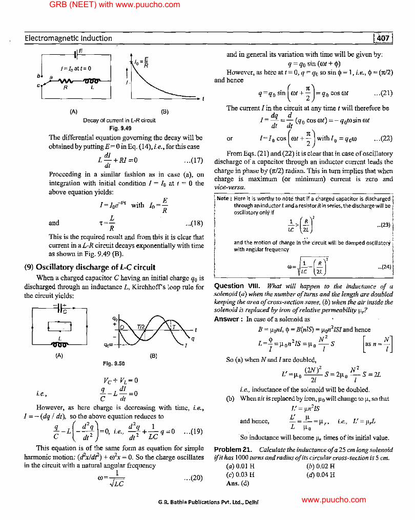
(9) Oscillatory discharge of l-C circuit
When a charged capacitor C having an initial charge q0 is discharged through an inductance L, Kirchhoff s loop rule for the circuit yields:
+ C
r t --l>L->.-'-'=.1--~-ll-!.-->.- t
L q
(A) (B)
Fig. 9.50
Ve+ Vi=O
i.e., q di --L-=0 C dt
However, as here charge is decreasing with time, i.e., I= - (dq I dt), so the above equation reduces to
:!1...-L(- d2
2q)=O, i.e., d2; +-1-q=O ... (19)
C dt dtLC
This equation is of the same form as equation for simple harmonic motion: (d2x!di1-) + ro2x = 0. So the charge oscillates in the circuit with a natural angular frequency
1 OJ= ../Le ... (20)
and in general its variation with time will be given by:
q = q0 sin (rot+<!>) However, as here at t= 0, q = q0 so sin <I>= 1, i.e., <I>= (n/2)
and hence
q=q0 sin(rot+;)=q0 cosrot ... (21)
The current J in the circuit at any time t will therefore be
I dq d( ) . =dt= dt q 0 cos rot =-q0rosmrot
or I= 10 cos (OJI+ f) with/0 = q0ro ... (22)
From Eqs. (21) and (22) it is clear that in case of oscillatory discharge of a capacitor through an inductor current leads the charge in phase by (7t/2) radian. This in tum implies that when charge is maximum ( or minimum) current is zero and vice-versa.
Note·: H_ere it is worthy to-nbte that'if a charged capacitor is discharged j through an inductor Land a re. si?.·tor R in series, the discharge.will be I oscillatory-only if
_l> (.!..)' ... (23) I LC 2L
- ,, l and the motion of charge in the circuit will be damped oscillatory with angular frequency
O>= L~ -(:J ... (24)
Question VIII. What will happen to the inductance of a solenoid (a) when the number of turns and the length are doubled keeping the area of cross-section same, (b) when the air inside the solenoid iii replaced by iron of relative permeability µr? Answer : In case of a solenoid as
B = µonl, <I>= B(nlS) = µon21SJ and hence
_<I> 2 N2 [ NJ L-1 =µ 0 11 IS=µ 0 -
1-s asn= 1
So (a) when N and I are doubled,
, (2N)2 N2 L =µ 0 --S=2µ 0 -S=2L
21 1 i.e., inductance of the solenoid will be doubled.
(b) When air is replaced by iron, µ0 will change to µ, so that
L' = µn 2/S
and hence, J: µ L=;,;-=µ,, i.e., L'=µ,L
So inductance will become µ, times of its initial value.
Problem 21. Calculate the inductance of a 25 cm long solenoid ifit has I 000 turns and radius of its circular cross-section is 5 cm.
(a) 0.01 H (b) 0.02 H (c) 0.03 H (d) 0.04 H Ans. (d)
G.R. Bathla Publications Pvt. Ltd., Delhi
GRB (NEET) with www.puucho.com
www.puucho.com
GRB Physics for Medical Entrance Exams (2nd Year Programme)
Solution : As for a solenoid
B=µo(41tN/) 41t L
So,
= 10-7 (41t X IOOO x/) 0.25
=16!cxl0--4 I
q,=B(NS)
= I61tx 10--4/x 103 x1ex(0.05)2
=4n2x 10-31
and hence L = (q,/1) = 41t2 x 10-3 = 0.04 H
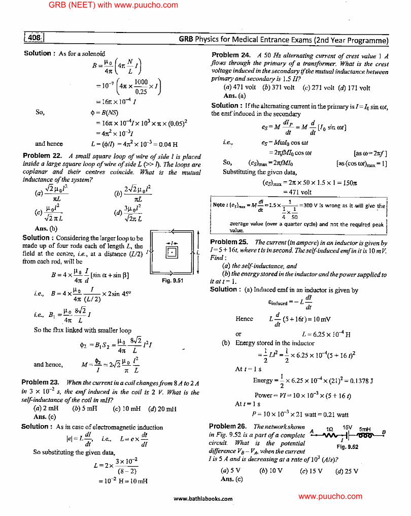
Problem 22. A small square loop of wire of side 1 is placed inside a large square loop of wire of side L (>> [). The loops are coplanar and their centres coincide. What is the mutual inductance of the system?
(a) Jiµol2 1tL
(c) µo/2 ..f2.1tL
Ans.(b) r=;i Solution : Considering the largerloop to be 1 -,. made up of four rods each of length L, the In] field at the cen:re, i.e., at a distance (L/2) 1 II tOJ ~ Lj
from each rod, will be bdJ B = 4 x ~ I [sin Cl +sin f3]
i.e.,
i.e.,
41t d Fig. 9.51
B=4xµ 0 -1-x2sin45°
41t (L/2)
B1 =~ g.fj_ I
_41t L
So the flux linked with smaller loop
µo if2 2 ql2 =B1S2 =---1 I
41t L
and hence, M= qJi = 2.Fz µ 0 I:_ / 7t L
Problem 23. When the current in a coil changes.from 8A to2A
in 3 x 10⁻² s, the emf induced in the coil is 2 V. What is the self-inductance of the coil in mH?
(a) 2 mH (b) 5 mH (c) IO mH (a) 20 mH Ans. (c)
Solution : As in case of electromagnetic induction di dt
lel=L-, i.e .. L=ex-dt di
So substituting the given data,
L=2x 3x 10-2 (8-2)
= 10-2 H= IOmH
Problem 24. A 50 Hz alternating current of crest value I A flows through the primary of a transformer. What is the crest voltage induced in the secondary if the mutual inductance between primary and secondary is 1.5 H?
(a) 471 volt (b) 371 volt (c) 271 volt (a) 171 volt Ans. (a)
Solution : If the alternating current in the primary is/= / 0 sin cot, the emf induced in the secondary
dip d . es=M-=M -[/0 smcot]
dt dt
i.e., es= Mcolo cos cot
= 21t.fM/o cos cot [ as co= 21tf]
So, (es)max =21t.fM/o [as (cos cot)max = I] Substituting the given data,
(es)max = 27t x 50 x 1.5 x I= 1507t
=471 volt I . i Note: (e5 )max =M di =1.Sx-
1 1
=300 Vis wrong·as it.will give-the/ dt -x2- · !
4 ~ I
average value (over a quarter cycle) and not the required peak II value.
Problem 25. The current (in ampere) in an inductor is given by I= 5 + I 61, where I is in second. The self-induced emf in it is IO m V. Find:
(a) the self-inductance, and ( b) the energy stored in the inductor and the power supplied to
itatt= I. Solution: (a) Induced emf in an inductor is given by
di ll;nduced = - L di
Hence d
L- (5+ 16t)= IOmV dt
or L = 6.25 X 10--4 H (b) Energy stored in the inductor
=_!:LP=.!_ x 6.25 x 10--4(5 + 16 1)2 2 2
Att=ls
Energy=.!.x 6.25 x I0--4x (21)2 = 0.1378 J 2
Power= VI= IO x 10-3 x (5 + 16 1) At t= Is
P = IO x 10-3 x 21 watt= 0.21 watt
Problem 26. The network shown 1Q 15V 5mH in Fig. 9.52 is a part of a complete ~~ circuit. What is the potential Fi~. 9_52 difference Vs- VA. when the current I is 5 A and is decreasing at a rate of I 03 (Als)?
(a) 5 V Ans. (c)
(b) IO V (c) 15 V (a) 25 V
www.bathlabooks.com
GRB (NEET) with www.puucho.com
www.puucho.com
Electromagnetic lnductio.n
Solution : In accordance with law of potential distribntion, for the given network,
dl VA -IR+E-L-=Vs
dt
and as here I is decreasing ( dll dt) is negative.
So V8 -VA=-5xl+l5-5x10⁻³(-103)
i.e., V8 -VA=-5+l5+5=15V
Problem 27. The equivalent inductance of two inductors is 2.4 H when connected in parallel and IO H when connected in series. What is the value of inductances of the individual inductors? Solution : As indnctances obey laws similar to 'grouping of resistances',
and (Li + Li)
Substituting the value of (L1 + L2) from first expression into second,
So that
i.e.,
and as
and
L1L2 = (2.4)(L1 + L2)
=2.4x 10=24
(L1 - L2J2 = (L1 + L2J2- 4L1L2
L1 -Lz = [(10)2-4 X 24] 112
=2H
L1 + L2 = 10 H, L1 = 6 H
L2=4H
Problem 28. On a cylindrical rod two coils are wound one above the other. What is the coefficient of mutual induction if the inductance of each coil is 0.1 H?
(a) 0.05 H (b) 0.10 H (c) 0.15 H (Ii) 0.20 H Ans. (b) ·
Solution : As one coil is wound over the other coupling is tight, i.e., k= 1, and so
M=~LiL, =~0.!x0.!=0.lH
Problem 29. The current in a coil of self-inductance 2.0 henry is increasing according to I= 2 sin?- A. Find the amount of energy spent during the period when the current changes from O to 2 A.
(a)l J (b) 2 J (c) 3 J (Ii) 4 J Ans. (d)
Solution : When the current in the coil is changing, work done in time dt
So,
i.e .•
dW=P dt = el dt =L dl xl dt dt
W=LJ Idl=2J: Idl
W=[l 2 ]ii =4J
[ase=L:~]
Problem 30. Two different coils have self-inductances L1 = 8 mH and Li = 2 mH At a certain instant the current in the two coils is increasing at the same constant rate and the power supplied to the
two coils is the same. Find the ratio of (a) induced voltage, (b) current and ( c) energy stored in the two coils at that instant.
Solution : (a) As, e = L dl dt
e1 Li So, -;;;;-e2 Li
= 8mH=4 2mH
(b) As, P = el= constt. [given J 11 e2 1 -=-=-So, 12 e1 4
( c) As energy stored in a coil, U = (l/2)LI2
So, ~~ =~ G~r =1Gr =¾ Problem 31. A solenoid of resistance 50 Q and inductance 80 His connected to a 200 V battery. How long will it take for the current to reach 50% of its final equilibrium value? Calculate the maximum energy stored. Solution : In case of growth of current in a L-R circuit,
I= Io(! - e-11,) E L
with Io=- and 1 = -R R
According to the given problem, 50 I
l=-xl0 =-10 100 2
S 1 -tit o, 2Io=I0(1-e ), i.e.,
i.e., t = 1(loge 2)
=¼(0.693)
= 80
X 0.693 = I.I 088 S 50
-tit 1 e =-2
Further, as energy stored in a coil is (l/2)L!2, l 2
So, Umax = - L(Imax) 2
E 200 And as Imax=I0 =-=-=4A
R 50
So, Umax = ~ X 80 X (4)2 = 640 J 2
Problem 32. A coil of inductance L = 50 x 10--<i henry and resistance = 0.5 Q is connected to a battery of emf = 5.0 V. A
resistance of IO Q is connected parallel to the coil. Now at some instant the connection of the battery is switched off Find the amount of heat generated in the coil after switching off the battery.
Solution : Total energy stored in the inductor= ..1c LI i; 2
G.R. Bathla Publications Pvt. Ltd., Delhi
GRB (NEET) with www.puucho.com
www.puucho.com
GRB Physics for Medical Entrance Exams (2nd Year Programme)
:. Fraction of energy lost across inductor
r LV2
=EL·--(R+r) 2r(R+r)
50x 10-6 X 52
2 X 0.5 (JO+ 0.5) 1.19x 10--4 J
9.4 Some Applications of Electromagnetic Induction
(A) Eddy Currents When a changing magnetic flux is applied to a bulk piece
of conducting material circulating currents called eddy currents• are induced in the material. Because the resistance of the bulk conductor is usually low, eddy currents often have large magnitudes and heat up the conductor.
/\ I \
I ' ~/ \ ,..::_
X X X X X 1 X X , X I \
Qhx X $<F ' Fx X X I
:x X X x' I X X X X
(A) (B)
Fig. 9.53
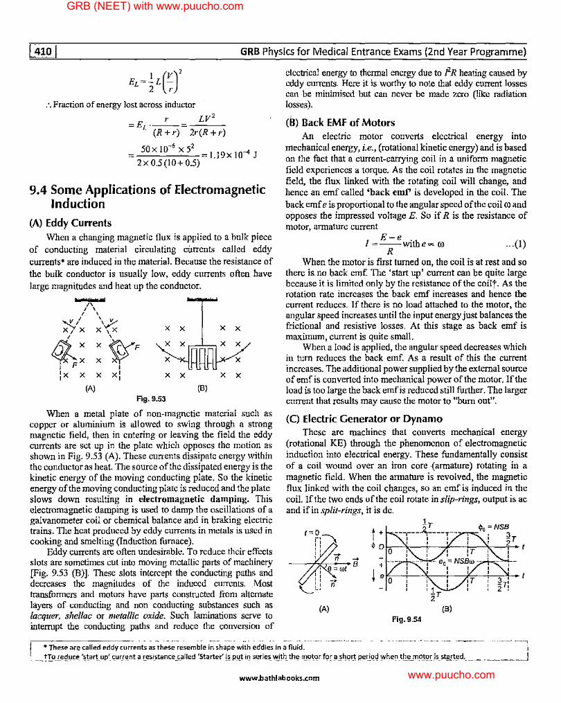
When a metal plate of non-magnetic material such as copper or aluminium is allowed to swing through a strong magnetic field, then in entering or leaving the field the eddy currents are set up in the plate which opposes the motion as shown in Fig. 9.53 (A). These currents dissipate energy within the conductor as heat. The source of the dissipated energy is the kinetic energy of the moving conducting plate. So the kinetic energy of the moving conducting plate is reduced and the plate slows down resulting in electromagnetic damping. This electromagnetic damping is used to damp the oscillations of a galvanometer coil or chemical balance and in braking electric trains. The heat produced by eddy currents in metals is used in cooking and smelting (Induction furnace).
Eddy currents are often undesirable. To reduce their effects slots are sometimes cut into moving metallic parts of machinery [Fig. 9.53 (B)]. These slots intercept the conducting paths and decreases the magnitudes of the induced currents. Most transformers and motors have parts constructed from alternate layers of conducting and non conducting substances such as lacquer, shellac or metallic oxide. Such laminations serve to interrupt the conducting paths and reduce the conversion of
electrical energy to thermal energy due to I2 R heating caused by eddy currents. Here it is worthy to note that eddy current losses can be minimised but can never be made zero (like radiation losses).
(B) Back EMF of Motors An electric motor converts electrical energy into
mechanical energy, i.e., (rotational kinetic energy) and is based on the fact that a current-carrying coil in a uniform magnetic field experiences a torque. As the coil rotates in the magnetic field, the flux linked with the rotating coil will change, and hence an emf called 'back emf' is developed in the coil. The back emf e is proportional to the angular speed of the coil co and opposes the impressed voltage E. So if R is the resistance of motor, annature current
E-e [=--withe~ co
R ... (!)
When the motor is first turned on, the coil is at rest and so there is.no back emf. The 'start up' current can be quite large because it is limited only by the resistance of the coilt. As the rotation rate increases the back emf increases and hence the current reduces. If there is no load attached to the motor, the angular speed increases until the input energy just balances the frictional and resistive losses. At this stage as back emf is maximum, current is quite small.
When a load is applied, the angular speed decreases which in tum reduces the back emf. As a result of this the current increases. The additional power supplied by the external source of emf is converted into mechanical power of the motor. If the load is too large the back emf is reduced still further. The larger current that results may cause the motor to "bum out".
(C) Electric Generator or Dynamo These are machines that converts mechanical energy
(rotational KE) through the phenomenon of electromagnetic induction into electrical energy. These fundamentally consist of a coil wound over an iron core {armature) rotating in a magnetic field. When the armature is revolved, the magnetic flux linked with the coil changes, so an emf is induced in the coil. If the two ends of the coil rotate in slip-rings, output is ac and if in split-rings, it is de.
1r
t + --,----~----T---1 I 0
$ Q I I I
0
t~ 0 11~ '' : ' '
,r
(A) Fig.9.54
---------- - - - - ··--·- - -- ---- -- ..... -- -- - - ------. ----·------·-· ----------- --- --- ······---, I • These are called eddy currents as these resemble in shape with eddies in a fluid. 'r
.. __ !!9._i.e~1,1c;e_ '~!ar!_up'_ <:_urn:~_nt ~ r..esi_stance _c_alled 'Starter' !~ p_4t iQ s_erie~ ~h_ th~ r11otqr f9r ~ 21-!qr:! J:!ei:_i.q~ '.Nhe~ _ttLtL m_c;iJQ[ _is_ st_gi_'1!!d-.. _____ , ______ J
www.bathlabooks.com
GRB (NEET) with www.puucho.com
www.puucho.com
Electromagnetic Induction
If initially the coil is perpendicular to the field, the flux linked with it at any time t, ·
<j,=BScos B=NSB cos rot [asS--; NSand0=rot]
And so e = - d<j, = NSB rosin rot dt
i.e.. e = eo sin rot with e0 =NSBro ... (2) Here it is worthy to note that in a generator the induced emf
lags the flux by (it/2) in phase, i.e., when the flux is maximum (i.e., the coil is vertical), the emf is zero and when the flux is zero (i.e., the coil is horizontal), the emf is maximum.
(D) Transformer
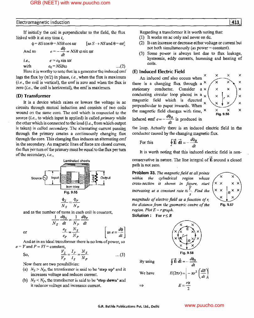
It is a device which raises or lowers the voltage in ac circuits through mutual induction and consists of two coils wound on the same core. The coil which is connected to the source (i.e., to which input is applied) is called primary while the other which is connected to the load (i.e., from which output is taken) is called secondary. The alternating current passing through the primary creates a continuously changing flux through the core. This changing flux induces an alternating emf in the secondary. As magnetic lines of force are closed curves, the flux per tum of the primary must be equal to the flux per tum of the secondary, i.e.,
Laminated sheets
Source l'V Input 'C _g Output
Fig. 9.55
<j,s <j,p --=--Ns Np
and as the number of turns in each coil is constant, I d<j,s I d<j,p
----=----Ns dt Np dt
or es= Ns ep Np
And as in an ideal transformer there is no loss of power, so e = V and P = VI= constant,
Vs Ip Ns -=-=--So, ... (3)
Now there are two possibilities: (a) Ns > Np, the transformer is said to be 'step up' and it
increases voltage and reduces current. (b) Ns < Np, the transformer is said to be 'step down' and
it reduces voltage and increases current.
Regarding a transformer it is worth noting that: (I) It works on ac only and never on de. (2) It can increase or decrease either voltage or current but
not both simultaneously (as power= constant). (3) Some power is always lost due to flux leakage,
hysteresis, eddy currents, humming and heating of coils.
(E) Induced Electric Field . X
An mduced emf also occurs when there is a changing flux through a x stationary conductor. Consider a x conducting circular loop placed in a x magnetic field which is directed perpendicular to paper inwards. When x the magnetic field changes with time, x . d d f d<j,B . d d . m uce em e = - -- 1s pro uce tn
dt
X X
X X
X X
X X Fig. 9.56
X
X
X
X
X
X
the loop. Actually there is an induced electric field in the conductor caused by the changing magnetic flux.
For this !i, in= - d<j,B J' dt
It is worth noting that this induced electric field is non-_,
conservative in nature. The line integral of E around a closed path is not zero.
Problem 33. The magnetic field at all points within the cylindrical region whose cross-section is shown in figure, start
. . T F. d h increasing at a constant rate a -. m t e s
magnitude of electric field as a function of r, the distance from the geometric centre of the region. Plot E - r graph. Solution : For r,,; R
By using
We have
Fig. 9.58
.fF, di= - d<j,B :r dt
E(21tr)=l-1tr2 (:)
E=rr,. 2
X X
X X X X
X X
X X
Fig. 9.57
G.R. Bathla Publications Pvt. Ltd., Delhi
GRB (NEET) with www.puucho.com
www.puucho.com
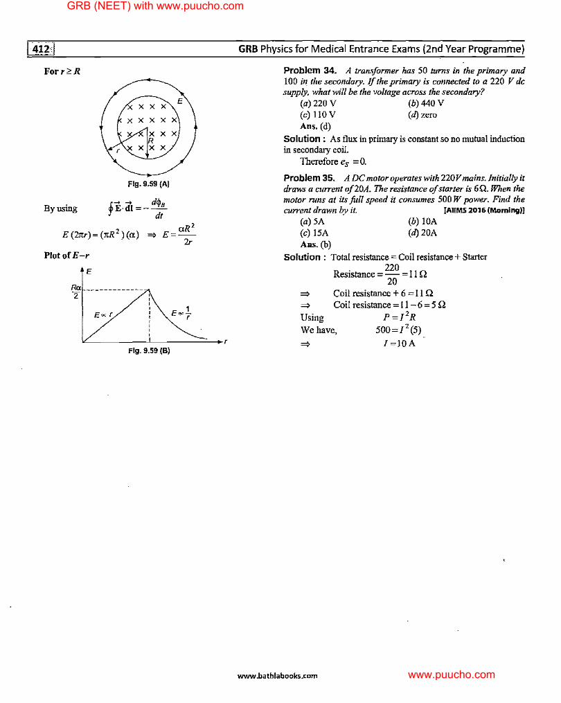
For r?.R
By using
XX
XX
Fig. 9.59 (A)
E
aR' E(21tr)=(1tR 2 )(a) ~ E=-
2r
Plot.of E-r
E Ra ____________ _ 2
E~r
\L.. _____ !.._ ___ _..::;:_::..._.,
Fig. 9.59 (B)
GRB Physics for Medical Entrance Exams (2nd Year Programme)
Problem 34. A transformer has 50 turns in the primary and I 00 in the secondary. If the primary is connected to a 220 V de supply, what will be the voltage across the secondary?
(a) 220 V (b) 440 V (c) llO V (d) zero Ans. (d)
Solution : As flux in primary is constant so no mutual induction in secondary coil.
Therefore e8 = 0.
Problem 35. A DC motor operates with 220V mains. Initially it draws a current of20A. The resistance of starter is 6Q. When the motor runs at its fall speed it consumes 500 W power. Find the current drawn by it. IAIIMS 2016 (Morning)!
(a) 5A (b) IOA (c) 15A (d) 20A Ans. (b)
Solution : Total resistance= Coil resistance+ Starter
Resistance = 220 = I I n 20
=} Coil resistance + 6 = II Q =} Coil resistance = I I - 6 = 5 Q
P=J 2R 500=1 2 (5)
Using
We have,
l=IOA
www.bathlabooks.com
GRB (NEET) with www.puucho.com
www.puucho.com
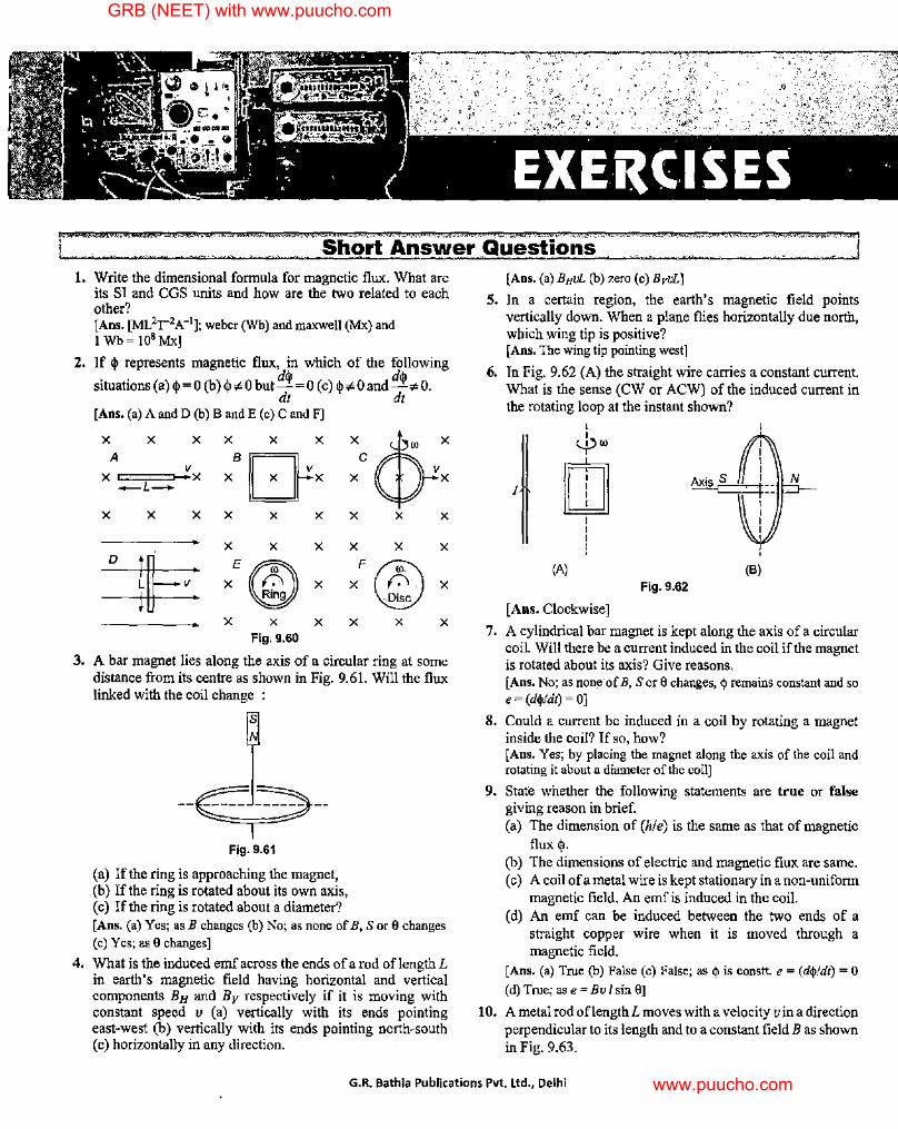
r 1. Write the dimensional formula for magnetic flux. What are
its SI and CGS units and how are the two related to each other? [Ans. [ML2r 2A-']; weber (Wb) and maxwell (Mx) and I Wb= 108 Mx]
2. If q, represents magnetic flux, in which of the following . . dq, dq,
s1tuat10ns (a) q,= 0 (b) q,;e O but-= 0 (c) q,¢O and-¢O. dt dt
[Ans. (a) A and D (b) Band E (c) C and F]
:,~,~: :- ~ : 1~: :, (1}: X X X X X X X X X
X X X X X X
~ E© F@ X t-' X X ·.(:\·. X Ring -.Disc
X X X X X X Fig. 9.60
3. A bar magnet lies along the axis of a circular ring at some distance from its centre as shown in Fig. 9.61. Will the flux linked with the coil change :
s
--~--
Fig. 9.61
(a) If the ring is approaching the magnet, (b) If the ring is rotated about its own axis, (c) If the ring is rotated about a diameter? [ Ans. ( a) Yes; as B changes (b) No; as none of B, S or 0 changes (c) Yes; as 0 changes]
4. What is the induced emf across the ends ofa rod oflength L in earth's magnetic field having horizontal and vertical components B H and B v respectively if it is moving with constant speed v (a) vertically with its ends pointing east-west (b) vertically with its ends pointing north-south ( c) horizontally in any direction.
[Ans. (a) BHvL (b) zero (c) BvvL]
5. In a certain region, the earth's magnetic field points vertically down. When a plane flies horizontally due north, which wing tip is positive? [Ans. The wing tip pointing west]
6. In Fig. 9.62 (A) the straight wire carries a constant current. What is the sense (CW or ACW) of the induced current in the rotating loop at the instant shown?
I I ½)<0
I rn I I I !
(A)
Fig. 9.62
[ Ans. Clockwise]
I I I I
Ax" S I ~::
N
I I I I
(B)
7. A cylindrical bar magnet is kept along the axis of a circular coil. Will there be a current induced in the coil if the magnet is rotated about its axis? Give reasons. [Ans. No; as none· of B, Sor 8 changes, q, remains constant and so e = (d$idt) = OJ
8. Could a current be induced in a coil by rotating a magnet inside the coil? If so, how? [Ans. Yes; by placing the magnet along the axis of the coil and rotating it about a diameter of the coil]
9. State whether the following statements are true or false giving reason in brief. (a) The dimension of (hie) is the same as that of magnetic
flux q,. (b) The dimensions of electric and magnetic flux are same. ( c) A coil of a metal wire is kept stationary in a non-uniform
magnetic field. An emf is induced in the coil. ( d) An emf can be induced between the two ends of a
straight copper wire when it is moved through a magnetic field.
[Ans. (a) True (b) False (c) False; as$ is constt. e = (d$ldt) = 0 (d) True; as e = Bv I sin 0]
10. A metal rod oflengthL moves with a velocity v in a direction perpendicular to its length and to a constant field B as shown in Fig. 9.63.
G.R. Bathla Publications Pvt. Ltd., Delhi
GRB (NEET) with www.puucho.com
www.puucho.com
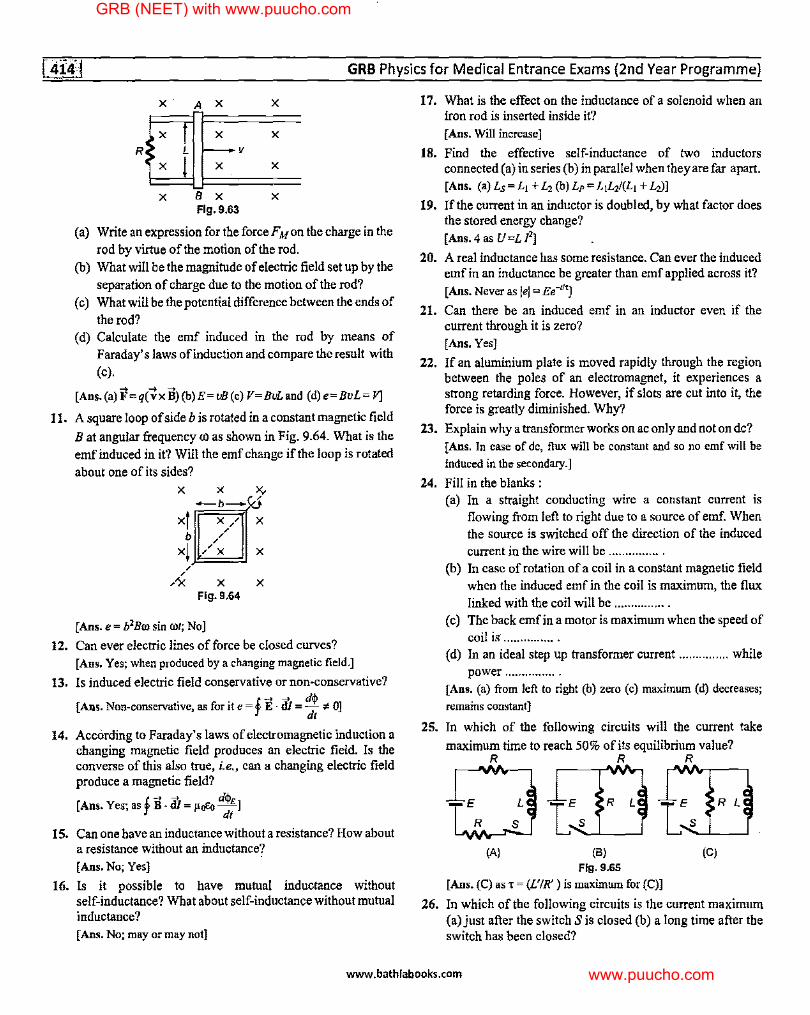
GRB Physics for Medical Entrance Exams (2nd Year Programme)
x· A X X
·i: ff· X
X
X B X X Fig. 9.63
(a) Write an expression for the forceFMon the charge in the
rod by virtue of the motion of the rod. (b) What will be the magnitude of electric field set up by the
separation of charge due to the motion of the rod?
( c) What will be the potential difference between the ends of
the rod? ( d) Calculate the emf induced in the rod by means of
Faraday's laws of induction and compare the result with
(c).
[Ans. (a) F=q(~x B)(b)E= vB (c) V=Bli.and (d) e=BvL= f']
11. A square loop of side b is rotated in a constant magnetic field
B at angular frequency co as shown in Fig. 9.64. What is the
emf induced in it? Will the emf change if the loop is rotated
about one of its sides? X X )y
-b-0 xf X/ X
b / /
/
xj /x X
/ /
,'X X X Fig. 9,64
[ Ans. e = b2 Bro sin rot; No J 12. Can ever electric lines of force be closed curves?
[Ans. Yes; when produced by a changing magnetic field.]
13. Is induced electric field conservative or non-conservative?
[Ans. Non-conservative, as for it e = ! E ·di= d$ c# OJ j dt
14. According to Faraday's laws of electromagnetic induction a changing magnetic field produces an electric field. Is the converse of this also true, i.e., can a changing electric field produce a magnetic field?
[Ans. Yes; as! B -di= µoE<, d$£] j dt
15. Can one have an inductance without a resistance? How about a resistance without an inductance?
[Ans. No; Yes]
16. Is it possible to have mutual inductance without self-inductance? What about self-inductance without mutual inductance? [Ans. No; may or may not]
17. What is the effect on the inductance of a solenoid when an iron rod is inserted inside it?
[ Ans. Will increase]
18. Find the effective self-inductance of two inductors connected (a) in series (b) in parallel when they are far apart.
[Ans. (a)Ls=L1 +L,(b)Lp=L1L,l(L1 +Li)]
19. If the current in an inductor is doubled, by what factor does the stored energy change?
[Ans. 4 as U=L I'] 20. A real inductance has some resistance. Can ever the induced
emf in an inductance be greater than emf applied across it?
[Ans. Never as l•I = Ee-ti']
21. Can there be an induced emf in an inductor even if the current through it is zero? [Ans. Yes]
22. If an aluminium plate is moved rapidly through the region between the poles of an electromagnet, it experiences a strong retarding force. However, if slots are cut into it, the force is greatly diminished. Why?
23. Explain why a transformer works on ac only and not on de? [ Ans. In case of de, flux will be constant and so no emf will be induced in the secondary.]
24. Fill in the blanks : (a) In a straight conducting wire a constant current is
flowing from left to right due to a source of emf. When the source is switched off the direction of the induced
current in the wire will be ............... . (b) In case of rotation ofa coil in a constant magnetic field
when the induced emf in the coil is maximum, the flux linked with the coil will be ............... .
(c) The back emfinamotoris maximum when the speed of coil is ............... .
( d) In an ideal step up transformer current ............... while power ............... .
[Ans. (a) from left to right (b) zero (c) maximum (d) decreases;
remains constant]
25. In which of the following circuits will the current take
maximum time to reach 50% of its equilibrium value?
E
R
R R R
(A)
L
s
(B)
Fig. 9.65
[Ans. (C) as~= (L'!R') is maximum for (C)]
R L
(C)
26. In which of the following circuits is the current maximum (a) just after the switch Sis closed (b) a long time after the switch has been closed?
www.bathlabooks.com
GRB (NEET) with www.puucho.com
www.puucho.com
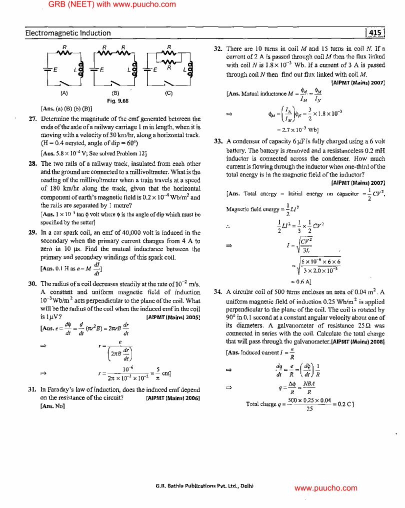
Electromagnetic Induction
27.
28.
29.
30.
31.
R R R
OL ...... , (A)
[Ans. (a) (B) (b) (B)]
(8)
Fig. 9.66
R
(C)
Determine the magnitude of the -emf generated between the ends of the axle of a railway carriage l min length, when it is moving with a velocity of30 km/hr, along a horizontal track. (H = 0.4 oersted, angle of dip = 60")
[Ans. 5.8 x J0-4V; See solved Problem 12]
The two rails of a railway track, insulated from each other and the ground are connected to a millivoltmeter. What is the reading of the millivoltmeter when a train travels at a speed of 180 km/hr along the track, given that the horizontal
component of earth's magnetic field is 0.2 x 1 o-4 Wb/m2 and the rails are separated by 1 metre?
[Ans. I x 10-3 tan$ volt where$ is the angle of dip which must be specified by the setter J
In a car spark coil, an emf of 40,000 volt is induced in the secondary when the primary current changes from 4 A to zero in 10 µs. Find the mutual inductance between the primary and secondary windings of this spark coil.
di [Ans. 0.1 Has e=M -]
dt
The radius ofa coil decreases steadily at the rate ono-2 mis. A constant and uniform magnetic field of induction 10-3Wb/m 2 acts perpendicular to the plane of the coil. What will be the radius of the coil when the induced emf in the coil is lµV? [AIPMT(Mains) 2005]
[Ans. e = d$ = !_ (1tr2 B) = 21trB dr dt dt dt
e r
(21tB :)
10-• 5 r --=---=-cm]
21t X 10-3 X 10⁻² 1t
In Faraday's law of induction, does the induced emf depend on the resistance of the circuit? [AIPMT (Mains) 2006]
[Ans. No]
32. There are 10 turns in coil Mand 15 turns in coil N. If a current of 2 A is passed through coil M then the flux linked with coil N is 1.8 x 10⁻³ Wb. If a current of 3 A is passed
through coil N then fmd out flux linked with coil M. [AIPMT (Mains) 2007]
[Ans. Mutual inductance M = $N = $M IM IN
(JN) 3 -3 $M= - $N=-Xl.8XJ0 IM 2
= 2.7 X 10⁻³ Wb]
33. A condenser of capacity 6 µFis fully charged using a 6 volt
battery. The battery is removed and a resistanceless 0.2 mH inductor is connected across the condenser. How much current is flowing through the inductor when one-third of the total energy is in the magnetic field of the inductor?
[AIPMT (Mains) 2007]
[Ans. Total energy = Initial energy on capacitor = ½ CV2,
Magnetic field energy=.!. LI 2
2
.!.LI'=.!.x.!.cv' 2 3 2
1 = ~cv' 3L
6x10-6 x6x6
3 X 2.0 X 10-3
= 0.6A]
34. A circular coil of 500 turns encloses an area of 0.04 m2 . A
uniform magnetic field of induction 0.25 Wb/m 2 is applied perpendicular to the plane of the coil. The coil is rotated by 90° in 0.1 second at a constant angular velocity about one of its diameters. A galvanometer of resistance 25 Q was connected in series with the coil. Calculate the total charge that will pass through the galvanometer.[AIPMT (Mains) 2008]
e [ Ans. Induced current I = -
R
dq _ e -(d$) I ---- - -dt R dt R
t.$ NBA q=-=--
R R
Total charge q 500 X 0.25 X 0.04
25 0.2CJ
G.R. Bathla Publications Pvt. Ltd., Delhi
GRB (NEET) with www.puucho.com
www.puucho.com
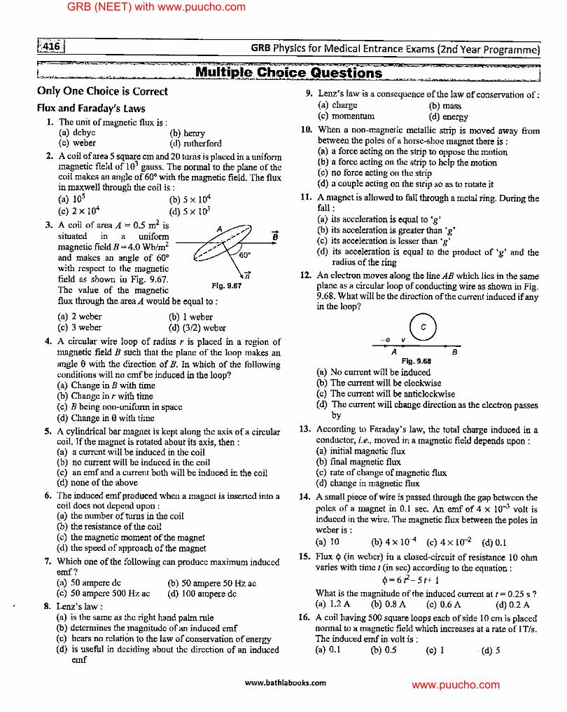
GRB Physics for Medical Entrance Exams (2nd Year Programme)
P··=-- ;&. ZC-.. :;;;: IL
1., ' Only One Choice is Correct
Flux and Faraday's laws 1. The unit of magnetic flux is :
(a) debye (b) heruy ( c) weber ( d) rutherford
2. A coil of area 5 square cm and 20 turns is placed in a uniform magnetic field of 103 gauss. The normal to the plane of the coil makes an angle of 60° with the magnetic field. The flux in maxwell through the coil is : (a) 105 (b) 5 X 10⁴
(c)2xl04 (d)5x!03
3. A coil of area A = 0.5 m2 is situated in a uniform magnetic field B = 4.0 Wb/m2 ---,,.C....,,<
and makes an angle of 60° with respect to the magnetic field as shown in Fig. 9.67. The value of the magnetic Fig. 9.67
flux through the area A would be equal to :
(a) 2 weber (b) 1 weber (c) 3 weber (d) (3/2) weber
-n
-B
4. A circular wire loop of radius r is placed in a region of magnetic field B such that the plane of the loop makes an angle 9 with the direction of B. In which of the following conditions will no emf be induced in the loop? (a) Change in B with time (b) Change in r with time ( c) B being non-uniform in space ( d) Change in 9 with time
5. A cylindrical bar magnet is kept along the axis of a circular coil. If the magnet is rotated about its axis, then : (a) a current will be induced in the coil (b) no current will be induced in the coil ( c) an emf and a current both will be induced in the coil (d) none of the above
6. The induced emf produced when a magnet is inserted into a coil does not depend upon : (a) the number of turns in the coil (b) the resistance of the coil ( c) the magnetic moment of the magnet (d) the speed of approach of the magnet
7. Which one of the following can produce maximum induced emf? (a) 50 ampere de (c) 50 ampere 500 Hz ac
8. Lenz's law:
(b) 50 ampere 50 Hz ac (d) 100 ampere de
(a) is the same as the right hand palm rule (b) determines the magnitude of an induced emf (c) bears no relation to the law of conservation of energy ( d) is nseful in deciding about the direction of an induced
emf
• ·-·= t .• ,,,..
~ "" "j 9. Lenz's law is a consequence of the law of conservation of:
(a) charge (b) mass ( c) momentum ( d) energy
10. When a non-magnetic metallic strip is moved away from between the poles of a horse-shoe magnet there is : (a) a force acting on the strip to oppose the motion (b) a force acting on the strip to help the motion (c) no force acting on the strip (d) a couple acting on the strip so as to rotate it
11. A magnet is allowed to fall through a metal ring. During the fall: (a) its acceleration is equal to 'g' (b ). its acceleration is greater than 'g' ( c) its acceleration is lesser than 'g' (d) its acceleratiorr is equal to the product of 'g' and the
radius of the ring
12. An electron moves along the line AB which lies in the same plane as a circular loop of conducting wire as shown in Fig. 9.68. Wbat will be the direction of the current induced if any in the loop?
13.
14.
15.
16.
-• A
Fig. 9.68 (a) No current will be induced (b) The current will be clockwise
B
( c) The current will be anticlockwise ( d) The current will change direction as the electron passes
by
According to Faraday's law, the total charge induced in a conductor, i.e., moved in a magnetic field depends upon : (a) initial magnetic flux (b) final magnetic flux (c) rate of change of magnetic flux ( d) change in magnetic flux
A small piece of wire is passed through the gap between the poles of a magnet in 0.1 sec. An emf of 4 x 10⁻³ volt is induced in the wire. The magnetic flux between the poles in weber is: (a) 10 (b) 4 X 10⁻⁴ (c) 4 X 10-Z (d) 0.J
Flux cj) (in weber) in a closed-circuit of resistance IO ohm varies with time t (in sec) according to the equation :
cj)=6t2-5t+ I
What is the magnitude of the induced current at t = 0.25 s? (a) 1.2 A (b) 0.8 A (c) 0.6 A (d) 0.2 A
A coil having 500 square loops each of side IO cm is placed normal to a magnetic field which increases at a rate of I T/s. The induced emf in volt is : (a) 0.1 (b) 0.5 (c) I · (d) 5
www.bathlabooks.com
GRB (NEET) with www.puucho.com
www.puucho.com
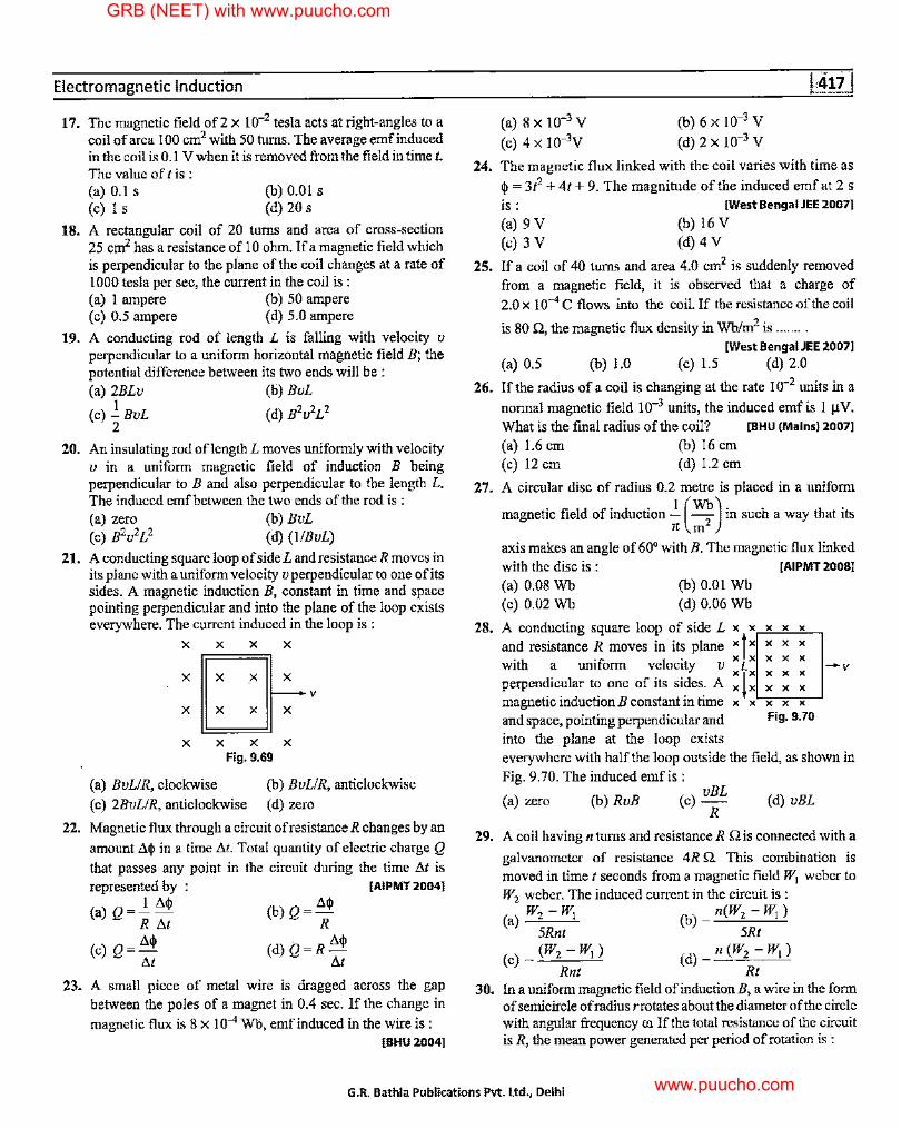
Electromagnetic Induction
17.
18.
19.
20.
21.
22.
The magnetic field of 2 x 10⁻² tesla acts at right-angles to a coil of area I 00 cm2 with 50 turns. The average emf induced in the coil is 0.1 V when it is removed from the field in time/. The value of I is : (a) 0.1 s (c) I s
(b) 0.01 s (d) 20 s
A rectangular coil of 20 tnrns and area of cross-section 25 cm2 has a resistance of 10 ohm. If a magnetic field which is perpendicular to the plane of the coil changes at a rate of 1000 tesla per sec, the current in the coil is : (a) 1 ampere (b) 50 ampere (c) 0.5 ampere (d) 5.0 ampere
A conducting rod of length L is falling with velocity v perpendicular to a uniform horizontal magnetic field B; the potential difference between its two ends will be : (a) 2BLv (b) BvL
I (c) -BvL (d) B2u2L2
2
An insulating rod oflength L moves uniformly with velocity u in a uniform magnetic field of induction B being perpendicular to B and also perpendicular to the length L. The induced emf between the two ends of the rod is : (a) zero (b) BvL (c) B2u2L2 (d) (1/BvL)
A conducting square loop of side L and resistance R moves in its plane with a uniform velocity uperpendicularto one of its sides. A magnetic induction B, constant in time and space pointing perpendicular and into the plane of the loop exists everywhere. The current induced in the loop is :
X X X X
X [J X
V
X X X
X X X X Fig. 9.69
(a) BvLIR, clockwise
(c) 2BvLIR, anticlockwise
(b) BvLIR, anticlockwise
(d) zero
Magnetic flux through a circuit ofresistance R changes by an
amount Aq, in a time At. Total quantity of electric charge Q that passes any point in the circuit during the time At is represented by [AIPMT 20041
(a) Q = __!_ Aq, R At
(c)Q=A<I> At
(b)Q=Aq, R
(d) Q=R Aq, At
23. A small piece of metal wire is dragged across the gap between the poles of a magnet in 0.4 sec. If the change in
magnetic flux is 8 x I 0-4 Wb, emf induced in the wire is : [SHU 2004]
24.
25.
26.
27.
28.
(a) 8 X 10⁻³ V
(c) 4 X 10⁻³y (b)6x10⁻³ V
(d) 2x 10⁻³ y
The magnetic flux linked with the coil varies with time as
q, = 3i2 + 41 + 9. The magnitude of the induced emf at 2 s
is : (a) 9V (c) 3 V
[West Bengal JEE 2007]
(b) 16 V (d) 4 V
If a coil of 40 turns and area 4.0 cm2 is suddenly removed from a magnetic field, it is observed that a charge of
2.0 x 10⁻⁴ C flows into the coil. If the resistance of the coil
is 80 n, the magnetic flux density in Wb/m2 is ....... . [West Bengal JEE 20071
(a) 0.5 (b) 1.0 (c) 1.5 (d) 2.0
If the radius of a coil is changing at the rate 10-2 units in a
normal magnetic field 10-3 units, the induced emf is 1 µV. What is the final radius of the coil? [SHU (Mains) 20071
(a) 1.6 cm (b) 16 cm (c) 12 cm (d) 1.2 cm
A circular disc of radius 0.2 metre is placed in a uniform
magnetic field of induction__!_ (Wb) in such a way that its 7t m2
axis makes an angle of 60° withB. The magnetic flux linked with the disc is : [AIPMT 20081
(a) 0.08 Wb (b) 0.01 Wb (c) 0.02 Wb (d) 0.06 Wb
A conducting square loop of side L x x x x x
and resistance R moves in its plane x f x x x x with a uniform velocity v x L x x x x - v perpendicular to one of its sides. A : ! : : : : magnetic induction B constant in time x x x x x and space, pointing perpendicular and Fig. 9. 70
into the plane at the loop exists everywhere with half the loop outside the field, as shown in Fig. 9.70. The induced emf is:
vBL (a) zero (b) RvB (c) - (d) vBL
R
29. A coil having n tnms and resistance R Q is connected with a
galvanometer of resistance 4R Q. This combination is moved in time t seconds from a magnetic field W1 weber to W2 weber. The induced current in the circuit is :
(a) W2 -Wj (b) _ n(W2 - W1) 5Rnt 5Rt
(c) _ (W2 -W1 ) (d) _ n (W2 - W1 )
Rnt Rt 30. In a uniform magnetic field ofinductionB, a wire in the form
of semicircle of radius rrotates about the diameter of the circle with angular frequency Cll If the total resistance of the circuit is R, the mean power generated per period of rotation is :
G.R. Bathla Publications Pvt. Ltd., Delhi
GRB (NEET) with www.puucho.com
www.puucho.com
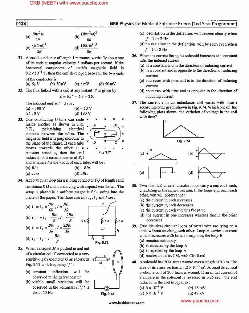
31.
32.
33.
GRB Physics for Medical Entrance Exams {2nd Year Programme)
(a) Bnr2
0J
2R
(c) (Bnroo)' 2R
(Bnr2oo)2
(b) SR
(d) (B1troo2 )2 8R
A metal conductor oflength I m rotates vertically about one of its ends at angular velocity 5 radians per second. If the horizontal component of earth's maguetic field is 0.2 x 10⁻⁴ T, ·then the emf developed between the two ends
of the conductor is : (a) 5µV (b) 50µV (c) 5mV (d) 50mV
The flux linked with a coil at any instant 't' is given by
<I>= 101 2 - 501 + 250
The induced emf at I = 3 s is : (a)-190V (b)-lOV (c) 10 V (d) 190 V
One conducting U-tube can slide x x x x x
inside another as shown in Fig. A a 9.71, maintaining electrical x ~~ x contacts between the tubes. The x f v x v..J x magnetic field Bis perpendicular to the plane of the figure. If each tube x D C x
moves towards the other at a x x x x x constant speed v, then the emf Fig. 9.71
induced in the circuit in terms of B, I and v, where I is the width of each tube, will be : (a) Blv (b) -B/v (c) zero (d) 2Blv
36.
37.
(c) oscillation in the deflection will be seen clearly when J=l or2Hz
(d) no variation in the deflection will be seen even when J= I or 2 Hz
When the current through a solenoid increases at a constant rate, the induced current : (a) is a constant and in the direction of inducing current (b) is a constant and is opposite to the direction of inducing
current (c) increases with time and is in the direction of inducing
current ( d) increases with time and is opposite to the direction of
inducing current
The current I in an inductance coil varies with time I accordingtothegraphshowninFig. 9.74. Which one of the following plots shows the variation of voltage in the coil with time?
Fig. 9.74
(a) +~
(b) =Pv ' t
(c) (d)
34. A rectangular loop has a sliding connector PQ oflength I and LP Pv
35.
resistance R Q and it is moving with a speed v as shown. The setup is placed in a uniform magnetic field going into the plane of the paper. The three currents / 1 ,I 2 and I are :
Blv Blv P 1
(a) 11 =/2 = 6R ,I= 3R
Blv 2Blv (b) 11 =-/2 =R,I=R Rn
Blv 2Blv (c) 11 =/2 = 3R ,I=3R
Blv (d)l1=l2=l=-
R
When a magnet Mis pushed in and out of a circular coil C connected to a very sensitive galvanometer G as shown in Fig. 9.73 with frequency 'f' : (a) constant deflection will be
observed in the galvanometer (b) visible small variation will be
observed in the voltmeter if 'f' is about 50 Hz
Rn
I
1, Q
Fig. 9.72
-Si=:::JN M
Fig. 9.73
Rn
38.
39.
40.
Two identical coaxial circular loops carry a current I each, circulating in the same direction. If the loops approach each other, you will observe that : (a) the current in each increases (b) the current in each decreases ( c) the current in each remains the same , ( d) the current in one increases whereas that in the other
decreases Two identical circular loops of metal wire are lying on a table without touching each other. Loop-A carries a current which increases with time. In response, the loop-B (a) remains stationary (b) is attracted by the loop-A (c) is repelled by the loop-A ( d) rotates about its CM, with CM fixed
A solenoid has 2000 turns wound over a length of0.3 m. The area of its cross-section is 1.2 x 10⁻³ m2. Around its central portion a coil of 300 turns is wound. If an initial current of 2 ampere in the solenoid is reversed in 0.25 sec, the emf induced in the coil is equal to : (a) 6 x 10⁻⁴ V (b) 48 mV
(c) 6 x 10⁻² V (d) 48 kV
www.bathlabooks.com
GRB (NEET) with www.puucho.com
www.puucho.com
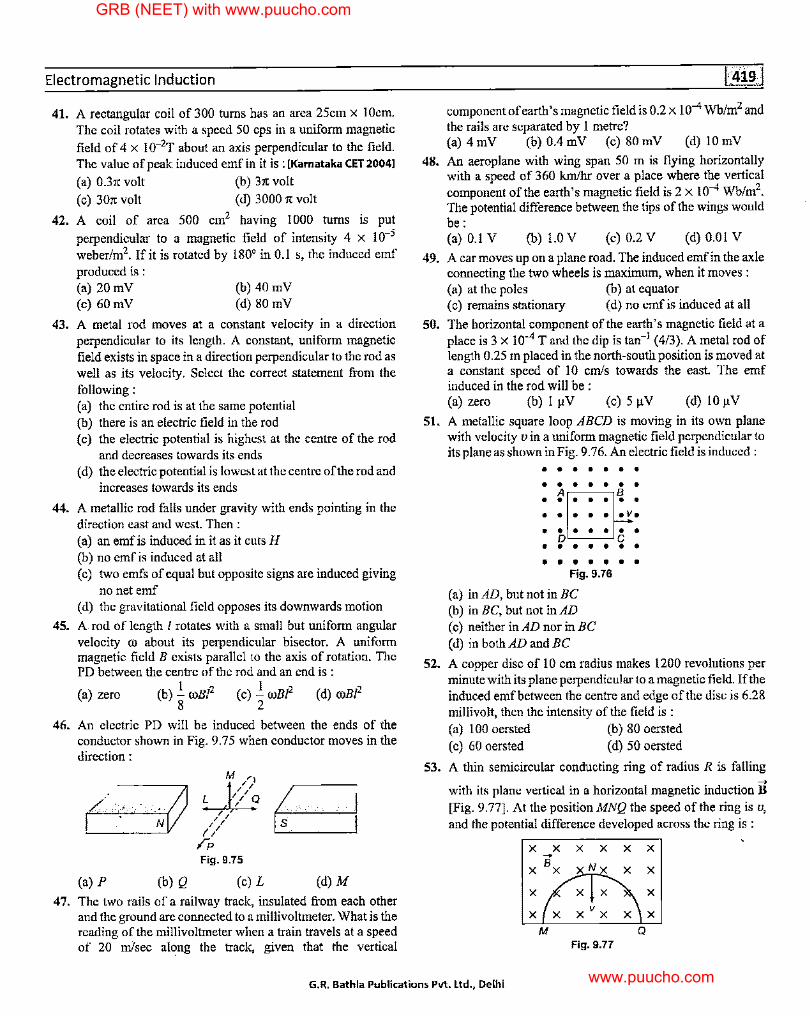
Electromagnetic Induction
41.
42.
43.
44.
45.
46.
A rectangular coil of 300 turns has an area 25cm x I 0cm. The coil rotates with a speed 50 cps in a uniform magnetic
field of 4 x 10⁻²T about an axis perpendicular to the field. The value of peak induced emf in it is : [Karnataka CET 2004]
(a) 0.3,c volt (b) 3,c volt
(c) 301t volt (d) 3000 ,c volt
A coil of area 500 cm2 having 1000 turns is put
perpendicular to a magnetic field of intensity 4 x 10⁻⁵
weber/m2• !fit is rotated by 180° in 0.1 s, the induced emf produced is : (a) 20 mV (c) 60 mV
(b) 40 mV (d) 80 mV
A metal rod moves at a constant velocity in a direction perpendicular to its length. A constant, uniform magnetic field exists in space in a direction perpendicular to the rod as well as its velocity. Select the correct statement from the following: (a) the entire rod is at the same potential (b) there is an electric field in the rod ( c) the electric potential is highest at the centre of the rod
and decreases towards its ends (d) the electric potential is lowest at the centre of the rod and
increases towards its ends
A metallic rod falls under gravity with ends pointing in the direction east and west. Then : (a) an emf is induced in it as it cuts H (b) no emf is induced at all (c) two emfs of equal but opposite signs are induced giving
no net emf ( d) the gravitational field opposes its downwards motion
A rod of length I rotates with a small but uniform angular velocity OJ about its perpendicular bisector. A uniform magnetic field B exists parallel to the axis of rotation. The PD between the centre of the rod and an end is :
(a) zero (b) .!. roB/2 (c) .!. 00B!2 (d) roB/2 8 2
An electric PD will be induced between the ends of the conductor shown in Fig. 9.75 when conductor moves in the direction:
(a) p (b) Q
~ /~/
// ;-p Fig. 9.75
(c) L
B (d) M
47. The two rails of a railway track, insulated from each other and the ground are connected to a millivoltmeter. What is the reading of the millivoltmeter when a train travels at a speed of 20 m/sec along the track, given that the vertical
48.
49.
50.
51.
52.
component of earth's magnetic field is 0.2 x I o-4 Wb/m2 and the rails are separated by I metre? (a) 4 mV (b) 0.4 mV (c) 80 mV (d) 10 mV
An aeroplane with wing span 50 m is flying horizontally with a speed of 360 km/hr over a place where the vertical component of the earth's magnetic field is 2 x 10⁻⁴ Wb/m2
•
The potential difference between the tips of the wings would be: (a) 0.1 V (b) 1.0 V (c) 0.2 V (d) 0.01 V
A car moves up on a plane road. The induced emfin the axle connecting the two wheels is maximum, when it moves : (a) at the poles (b) at equator (c) remains stationary (d) no emf is induced at all
The horizontal component of the earth's magnetic field at a place is 3 x 10⁻⁴ T and the dip is tan-1 (4/3). A metal rod of length 0.25 m placed in the north-south position is moved at a constant speed of l 0 emfs towards the east. The emf induced in the rod will be : (a) zero (b) I µV (c) 5 µV (d) 10 µV
A metallic square loop ABCD is moving in its own plane with velocity v in a uniform magnetic field perpendicular to its plane as shown in Fig. 9.76. An electric field is induced :
••••••• ••••••• A~-~B ••••••• • •••• • v.
••••••• o~-~c ••••••• • • • • • • •
Fig. 9.76
(a) in AD, but not in BC (b) in BC, but not in AD (c) neither in AD nor in BC ( d) in both AD and BC
A copper disc of 10 cm radius makes 1200 revolutions per minute with its plane perpendicular to a magnetic field. If the induced emf between the centre and edge of the disc is 6.28 millivolt, then the intensity of the field is : (a) 100 oersted (b) 80 oersted (c) 60 oersted (d) 50 oersted
53. A thin semicircular conducting ring of radius R is falling ...,
with its plane vertical in a horizontal magnetic induction B [Fig. 9.77]. At the positionMNQ the speed of the ring is v, and the potential difference developed across the ring is :
X X X X X X -B X X xNx X X
X X X X
X X xvx X X
M Q Fig. 9.77
G.R. Bathla Publications Pvt. Ltd., Delhi
GRB (NEET) with www.puucho.com
www.puucho.com
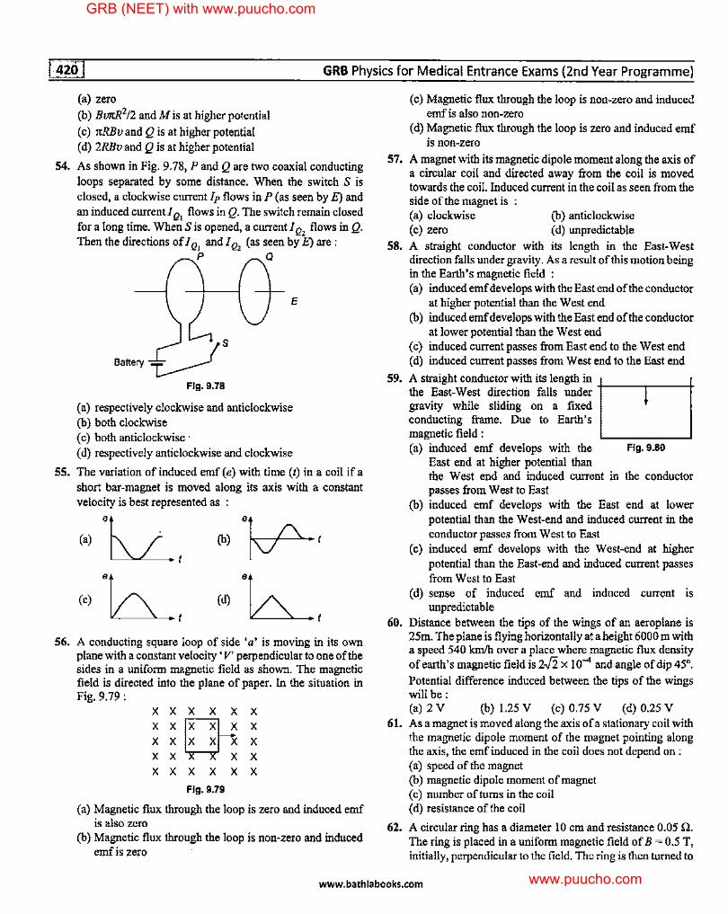
54.
55.
56.
GRB Physics for Medical Entrance Exams (2nd Year Programme)
(a) zero
(b) BllltR2!2 and Mis at higher potential
( c) rrRBv and Q is at higher potential ( d) 2RBv and Q is at higher potential
As shown in Fig. 9.78, P and Qare two coaxial conducting loops separated by some distance. When the switch S is closed, a clockwise current Ip flows in P ( as seen by E) and an induced current/ Q, flows in Q. The switch remain closed for a long time. When Sis opened, a current/ Q, flows in Q. Then the directions of/ Q, and/ Q, (as seen by E) are:
p Q
E
Battery £._is Fig. 9.78
(a) respectively clockwise and anticlockwise (b) both clockwise (c) both anticlockwise· ( d) respectively anticlockwise and clockwise
The variation of induced emf (e) with time (t) in a coil if a short bar-magnet is moved along its axis with a constant velocity is best represented as :
(a) "lL__t (c) "6..___t
(b) ·~t
(d) "b___t A conducting square loop of side 'a' is moving in its own plane with a constant velocity' V' perpendicular to one of the sides in a uniform magnetic field as shown. The magnetic field is directed into the plane of paper. In the situation in Fig. 9.79:
xxxxxx
;;~; xxxxxx
Fig. 9.79
(a) Magnetic flux through the loop is zero and induced emf is also zero
(b) Magnetic flux through the loop is non-zero and induced emf is zero
57.
58.
59.
60.
61.
62.
(c) Magnetic flux through the loop is non-zero and induced emf is also non-zero
( d) Magnetic flux through the loop is zero and induced emf is non-zero
A magnet with its magnetic dipole moment along the axis of a circular coil and directed away from the coil is moved towards the coil. Induced current in the coil as seen from the side of the magnet is (a) clockwise (c) zero
(b) anticlockwise ( d) unpredictable
A straight conductor with its length in the East-West direction falls under gravity. As a result of this motion being in the Earth's magnetic field : (a) induced emf develops with the East end of the conductor
at higher potential than the West end (b) induced emf develops with the East end of the conductor
at lower potential than the West end ( c) induced current passes from East end to the West end ( d) induced current passes from West end to the East end
A straight condnctor with its length in the East-West direction falls under +----j.---+ gravity while sliding on a fixed condncting frame. Due to Earth's magnetic field : (a) induced emf develops with the
East end at higher potential than Fig. 9,80
the West end and induced current in the conductor passes from West to East
(b) induced emf develops with the East end at lower potential than the West-end and induced current in the conductor passes from West to East
(c) induced emf develops with the West-end at higher potential than the East-end and induced current passes from West to East
( d) sense of induced emf and induced current is unpredictable
Distance between the tips of the wings of an aeroplane is 25m. The plane is flying horizontally at a height 6000 m with a speed 540 km/h over a place where magnetic flux density of earth's magnetic field is 2-.fi x 10-4 and angle of dip 45°.
Potential difference induced between the tips of the wings will be: (a) 2 V (b) 1.25 V (c) 0.75 V (d) 0.25 V As a magnet is moved along the axis of a stationary coil with the magnetic dipole moment of the magnet pointing along the axis, the emf induced in the coil does not depend on : (a) speed of the magnet (b) magnetic dipole moment of magnet ( c) number of turns in the coil ( d) resistance of the coil
A circular ring has a diameter 10 cm and resistance 0.05 n. The ring is placed in a uniform magnetic field of B = 0.5 T, initially, perpendicular to the field. The ring is then turned to
www.bathlabooks.com
GRB (NEET) with www.puucho.com
www.puucho.com
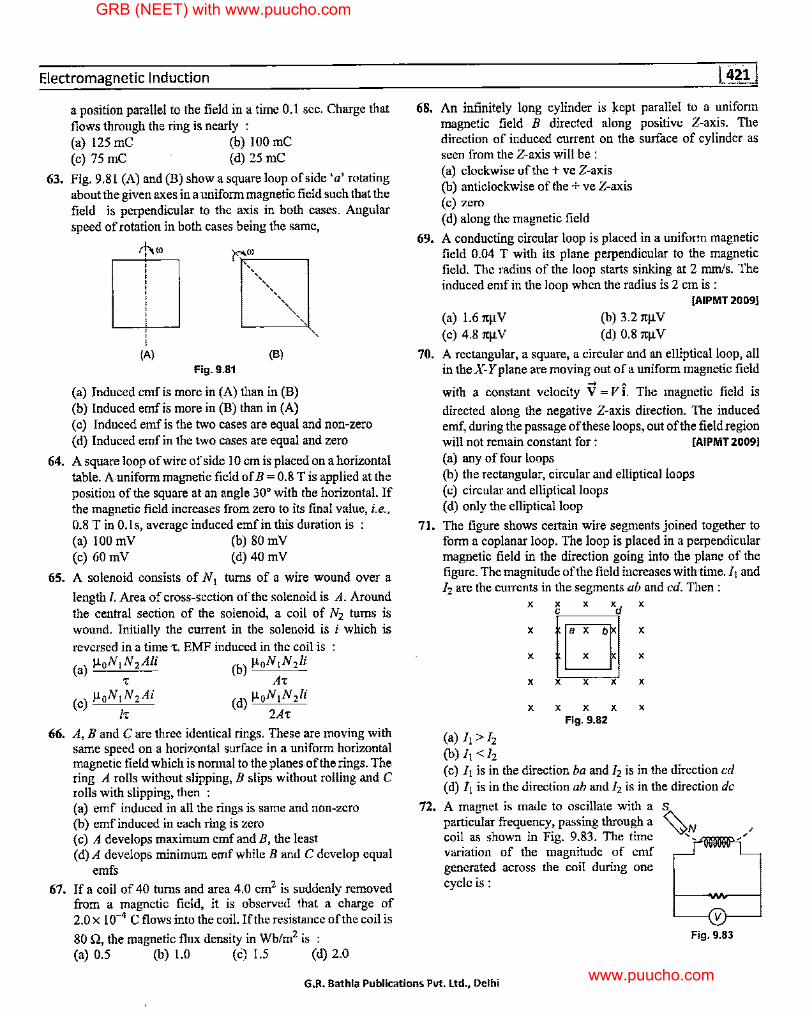
Electromagnetic Induction
a position parallel to the field in a time 0.1 sec. Charge that flows through the ring is nearly : (a) 125 mC (b) 100 mC (c) 75 me (d) 25 me
63. Fig. 9.81 (A) and (B) show a square loop of side 'a' rotating about the given axes in a uniform magnetic field such that the field is perpendicular to the axis in both cases. Angular speed of rotation in both cases being the same,
64.
65.
66.
67.
' (A) (B)
Fig. 9.81
(a) Induced emf is more in (A) than in (B) (b) Induced emf is more in (B) than in (A) ( c) Induced emf is the two cases are equal and non-zero ( d) Induced emf in the two cases are equal and zero
A square loop of wire of side 10 cm is placed on a horizontal table. A uniform magnetic field of B = 0.8 Tis applied at the position of the square at an angle 30° with the horizontal. If the magnetic field increases from zero to its final value, i.e.,
0.8 Tin 0.ls, average induced emf in this duration is (a) 100 mV (b) 80 mV (c) 60 mV (d) 40 mV
A solenoid consists of N 1 turns of a wire wound over a
length/. Area of cross-section of the solenoid is A. Around the central section of the solenoid, a coil of N2 turns is wound. Initially the current in the solenoid is i which is reversed in a time T. EMF induced in the coil is (a) µ0N 1N 2 Ali (b) µ 0N 1N 2 /i
T AT (c) µoN,N 2 Ai (d) µ 0N 1N 2 /i
IT 2AT
A, B and Care three identical rings. These are moving with same speed on a horizontal surface in a uniform horizontal magnetic field which is normal to the planes of the rings. The ring A rolls without slipping, B slips without rolling and C rolls with slipping, then : (a) emf induced in all the rings is same and non-zero (b) emf induced in each ring is zero ( c) A develops maximum emf and B, the least ( d) A develops minimum emf while B and C develop equal
emfs
If a coil of 40 turns and area 4.0 cm2 is suddenly removed from a magnetic field, it is observed that a charge of 2.0 x 10⁻⁴ C flows into the coil. If the resistance of the coil is
80 n, the magnetic flux density in Wb/m2 is : (a) 0.5 (b) 1.0 (c) 1.5 (d) 2.0
68. An infinitely long cylinder is kept parallel to a uniform magnetic field B directed along positive Z-axis. The direction of induced current on the surface of cylinder as seen from the Z-axis will be :
69.
70.
71.
72.
(a) clockwise of the+ ve Z-axis (b) anticlockwise of the + ve Z-axis (c) zero ( d) along the magnetic field
A conducting circular loop is placed in a uniform magnetic field 0.04 T with its plane perpendicular to the magnetic field. The radius of the loop starts sinking at 2 mm/s. The induced emf in the loop when the radius is 2 cm is :
(a) 1.6 1tµV (c) 4.8 1tµV
(b) 3.2 1tµV (d) 0.8 1tµV
[AIPMT 2009]
A rectangular, a square, a circular and an elliptical loop, all in the X-Yplane are moving out of a uniform magnetic field
-> A
with a constant velocity V =Vi. The magnetic field is
directed along the negative Z-axis direction. The induced emf, during the passage of these loops, out of the field region will not remain constant for : [AIPMT 20091
(a) any of four loops (b) the rectangular, circular and elliptical loops ( c) circular and ellipticalloops ( d) only the elliptical loop
The figure shows certain wire segments joined together to form a coplanar loop. The loop is placed in a perpendicular magnetic field in the direction going into the plane of the figure. The magnitude of the field increases with time. J1 and Ii are the currents in the segments ab and ed. Then :
(a) Ii> Ii (b)I,<fi
X
X
X
X
X
X X xd X C
D X
X
X X X X
X X X X
Fig. 9.82
( c) Ji is in the direction ba and Ji is in the direction ed (d) I, is in the direction ab and Ii is in the direction de
A magnet is made to oscillate with a S
particular frequency, passing through a ~-/'/_ coil as shown in Fig. 9.83. The time -r'ijlffll!l!P, variation of the magnitude of emf generated across the coil during one cycle is:
~--1v\--...l
Fig. 9.83
G.R. Bathla Publications Pvt. Ltd., Delhi
GRB (NEET) with www.puucho.com
www.puucho.com
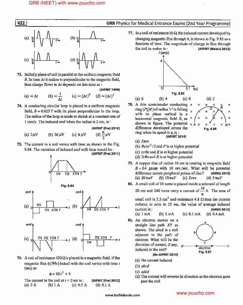
GRB Physics for Medical Entrance Exams {2nd Year Programme)
73.
74.
(a)]~
(c)]~
Initially plane of coil is parallel to the uniform magnetic field B. In time !ii it makes to perpendicular to the magnetic field, then charge flows in !ii depends on this time as :
(a) ~ lit I
(b) ~-lit
[AIPMT 19991
(c) ~ (lit)" (d) ~ (lit)2
A conducting circular loop is placed in a uniform magnetic
field, B = 0.025 T with its plane perpendicular to the loop. The radius of the loop is made to shrink at a constant rate of
I mm/s. The induced emf when the radius is 2 cm, is:
[AIPMT (Pre) 20101
(a) 2µV (b) 21tµV (c) itµV (d) ~µV . 2
75. The current in a coil varies with time as shown in the Fig.
9.84. The variation of induced emf with time would be: [AIPMT (Pre) 20111
Fig. 9.84
emf emf
(a) f--r/.,...4~_,..__ .... O T/2 3T/4 T
emf emf
76. A coil ofresistance 400Qis placed in a magnetic field. If the
magnetic flux q, (Wb) linked with the coil varies with time t (sec) as
q,=501 2 +4
The current in the coil at t = 2 sec is : (a)2A (b)IA (c)0.5A
[AIPMT (Pre) 20121
(d) 0.1 A
77. In a coil ofresistance IO Q, the induced current developed by
changing magnetic flux through it, is shown in Fig. 9.85 as a function of time. The magnitude of change in flux through the coil in weber is : · [AIPMT (Mains) 20121
78.
!(amp)
4
0
(a) 6 (b) 4
0.1 ~s) Fig. 9.85
(c) 8 (d) 2
A thin semicircular conducting x x x x x x
ring(PQR)ofradius'r'isfalling x (:Ax with its plane vertical in a horizontal magnetic field B, as x x x shown in figure. The potential x p x x x x Rx difference developed across the Fig. 9.86 ring when its speed is v, is :
[AIPMT 20141
(a) Zero (b) Bvitr2 12 and P is at higher potential
( c) itrBv and R is at higher potential (d) 2rBvand R is at higher potential
79. A copper disc of radius 10 cm is rotating in magnetic field B = 0.4 gauss with 10 rev./sec. What will be potential difference across peripheral points of disc? [AIIMS 201 s1
(a) 20ituV (b) !OituV (c) Zero (d) 51tuV
80. A small coil of 10 turns is placed inside a solenoid oflength 10
20 cm and 240 turns carry a current of - A. The area of
81.
7t
small coil is 2.5 cm2 and resistance 4.8 Q then the current reduces to zero in 25 ms, the value of average induced current is : [AIIMS 20151
(a) I mA (b) 2 mA (c) 0.1 mA (d) 0.4 mA
An electron moves on a straight line path XY as shown. The abed is a coil adjacent to the path of electron. What will be the direction of current, if any, induced in the coil?
[Re-AIPMT 201 SI
(a) No current induced
(b) abed
(c) aded
C
X·· · · ·· · · ·--e"'"le-ct,-r-on-+-· • • · • •• • • y
Fig. 9.87
( d) The current will reverse its direction as the electron goes past the coil
www.bathlabooks.com
GRB (NEET) with www.puucho.com
www.puucho.com
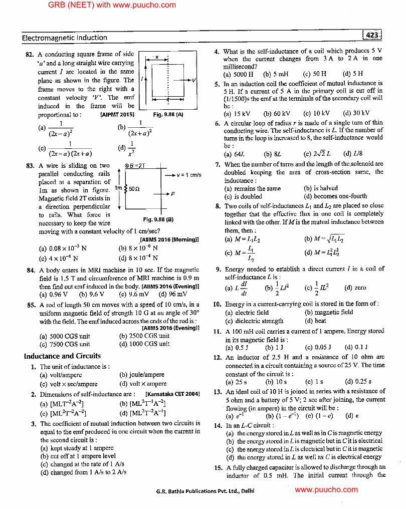
Electromagnetic Induction
82. A conducting square frame of side ·x 'a' and a long straight wire carrying
current I are located in the same plane as shown in the figure. The I
frame moves to the right with a constant velocity 'V'. The emf induced in the frame will be proportional to: [AIPMT 20151
I (a) (2x-a)2
(c) I (2x-a)(2x+a)
{b) 1 (2x+a)2
(d) _I_ x2
Fig. 9.88 (A)
83. A wire is· sliding on two :e®c.sBc::=:.,2,.,_T_--1_ parallel conducting rails i placed at a separation of
--+ v = 1 cm/s
Im as shown in figure. 1 m 50 n Magnetic field 2T exists in l a direction perpendicular L--------1-
to rails. What force is necessary to keep the wire
Fig. 9.88 (B)
moving with a constant velocity of 1 cm/sec?
(a) 0.08 X 10⁻³ N
(c) 4 X 10⁻⁶ N
[AIIMS 2016 (Morning)!
(b) 8x-l0-6N
(d) 8 X 10⁻⁴ N
84. A body enters in MRI machine in 10 sec. If the magnetic field is 1.5 T and circumference of MRI machine is 0.9 m then find out emf induced in the body. [AIIMS 2016 (Evening)!
85.
(a) 0.96 V (b) 9.6 V (c) 9.6 mV (d) 96 mV
A rod of length 50 cm moves with a speed of IO emfs, in a uniform magnetic field of strength 10 G at an angle of30° with the field. The emfinduced across the ends of the rod is :
(a) 5000 CGS unit (c) 7500 CGS unit
[AIIMS 2016 (Evening)]
(b) 2500 CGS unit ( d) 1000 CGS unit
Inductance and Circuits
1. The unit of inductance is : (a) volt/ampere
(c) volt x sec/ampere
(b) joule/ampere
( d) volt x ampere
2. Dimensions of self-inductance are : [Karnataka CET 20041
(a) [ML,2A-2] (b) [ML2,1A-2]
(c) [ML2, 2A-2] (d) [ML2, 2A-1]
3. The coefficient of mutual induction between two circuits is equal to the emf produced in one circuit when the current in the second circuit is : (a) kept steady at 1 ampere (b) cut off at 1 ampere level (c) changed at the rate of 1 A/s ( d) changed from I A/s to 2 A/s
4. What is the self-inductance of a coil which produces 5 V when the current changes from 3 A to 2 A in one millisecond? · (a) 5000 H (b) 5 mH (c) 50 H (d) 5 H
5. In an induction coil the coefficient of mutual inductance is 5 H. If a current of 5 A in the primary coil is cut off in (l/1500)s the emf at the terminals of the secondary coil will be: (a) 15 kV (b) 60 kV (c) 10 kV (d) 30 kV
6. A circular loop of radius r is made of a single tum of thin conducting wire. The self-inductance is L. If the number of turns in the loop is increased to 8, the self-inductance would be: (a) 64£ (b) 8£ (c) 2..fi. L (d) L/8
7. When the number of turns and the length of the.solenoid are doubled keeping the area of cross-section same, the inductance : (a) remains the same (c) is doubled
(b) is halved ( d) becomes one-fourth
8. Two coils of self-inductances £ 1 and £ 2 are placed so close together that the effective flux in one coil is completely linked with the other. If Mis the mutual inductance between them, then: (a) M=L1L2
L (c) M= ...J...
L,
(b) M= ~£-.£,
(d)M=£i4
9. Energy needed to establish a direct current I in a coil of self-inductance L is :
(a) L di (b) !.u2 dt 2
(d) zero
10. Energy in a current-carrying coil is stored in the form of: (a) electric field (b) magnetic field (c) dielectric strength (d) heat
11. A 100 mH coil carries a current of 1 ampere. Energy stored in its magnetic field is : (a) 0.5 J (b) 1 J (c) 0.05 J (d) 0.1 J
12. An inductor of 2.5 H and a resistance of 10 ohm are connected in a circuit containing a source of25 V. The time
constant of the circuit is : (a) 25 s (b) 10 s (c) 1 s (d) 0.25 s
13. An ideal coil oflO His joined in series with a resistance of 5 ohm and a battery of 5 V; 2 sec after joining, the current
· flowing (in ampere) in the circuit will be: · (a) e-1 (b) (l - e-1) (c) (1 - e) (d) e
14. In an L-C circuit : (a) the energy stored in£ as well as in Cis magnetic energy (b) the energy stored in£ is magnetic but in Cit is electrical ( c) the energy stored in L is electrical but in Cit is magnetic ( d) the energy stored in L as well as C is electric.al energy
15. A fully charged capacitor is allowed to discharge through an inductor of 0.5 mH. The initial current through the
G.R. Bathla Publications Pvt. Ltd., Delhi
GRB (NEET) with www.puucho.com
www.puucho.com
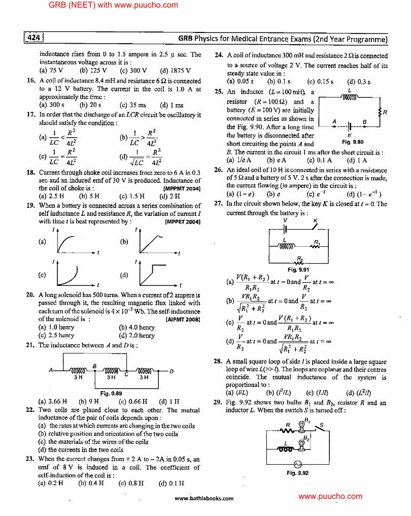
GRB Physics for Medical Entrance Exams (2nd Year Programme)
inductance rises from O to 1.5 ampere in 2.5 µ sec. The instantaneous voltagi, across it is : (a) 75 V (b) 125 V (c) 300 V (d) 1875 V
16. A coil of inductance 8.4 mH and resistance 6 n is connected to a 12 V battery. The current in the coil is 1.0 A at approximately the time : (a) 500 s (b) 20 s (c) 35 ms (d) 1 ms
17. In order that the discharge of an LCR circuit be oscillatory it should satisfy the condition :
I R 2 1 R 2
(a)-<- (b)->-LC 4L2 LC 4L2
I R 2 I R 2
(c)-=- (d)-=-LC 4L2 ./Le 4L2
18. Current through choke coil increases from zero to 6 A in 0.3 sec and an induced emf of 3 0 V is produced. Inductance of the coil of choke is : (MPPMT20041
(a) 2.5 H (b) 5 H (c) 1.5 H (d) 2 H 19. When a battery is connected across a series combination of
self inductance L and resistance R, the variation of current I with time I is best represented by : lMPPET 20041
(a)
1Lt (c) IU___t
(b) /Lc____t
(d) /~t
20. A long solenoid has 500 turns. When a current of2 ampere is passed through it, the resulting magnetic flux linked with each turn of the solenoid is 4 x 10⁻³ Wb. The self-inductance of the solenoid is (AIPMT 20081
(a) 1.0 henry (b) 4.0 henry (c) 2.5 henry (d) 2.0 henry
21. The inductance between A and Dis :
,~, Fig. 9.89
(a) 3.66 H (b) 9 H (c) 0.66 H (d) I H 22. Two coils are placed close to each other. The mutual
inductance of the pair of coils depends upon : (a) the rates at which currents are changing in the two coils (b) relative position and orientation of the two coils (c) the materials of the wires of the coils ( d) the currents in the two coils
23. When the current changes from+ 2 A to - 2A in 0.05 s, an emf of 8 V is induced in a coil. The coefficient of self-induction of the coil is : (a) 0.2 H (b) 0.4 H (c) 0.8 H (d) 0.1 H
24. A coil of inductance 300 mH and resistance 2 n is connected
to a source of voltage 2 V. The current reaches half of its steady state value in : (a) 0.05 s (b) 0.1 s (c) 0.15 s (d) 0.3 s
25. An inductor (L = I 00 mH1 a
resistor (R = 100 Q) and a
L
battery (E = 100 V) are initially connected in series as shown in the Fig. 9.90. After a long time A ----JI---- 8
the battery is disconnected after E short circuiting the points A and Fig. 9.90
B. The current in the circuit I ms after the short circuit is : (a) 1/eA (b) eA (c) 0.1 A (d) I A
R
26. An ideal coil of IO H is connected in series with a resistance of 5 Q and a battery of 5 V. 2 s after the connection is made, the current flowing (in ampere) in the circuit is: (a) (1-e) (b) e (c) e-1 (d) (l-e-1 )
27. In the circuit shown below, the key K is closed at t = a The
current through the battery is :
----"v,,_ __ ~5 L R,
R
Fig. 9.91
(a) V(R, +R2 ) at I= Oand_!'.'._ atl= = R1R2 R2
(b) VR,R 2 att = Oand_!'.'._ att = = ~Rf +Ri R2
(c) !:'._at/= Oand V(R, +R2 ) att == R2 R1R2 V VR R
(d)-att=Oand 1 2 att== R2 ~Rf +Ri
28. A small square loop of side I is placed inside a large square loop ofwireL(>> T). The loops are coplanar and their centres coincide. The mutual inductance of the system is proportional to : (a) (/IL) (b) (12/L) (c) (LIT)
29. Fig. 9.92 shows two bulbs B1 and B2, resistor R and an inductor L. When the switch Sis turned off:
Fig. 9.92
www.bathlabooks.com
GRB (NEET) with www.puucho.com
www.puucho.com
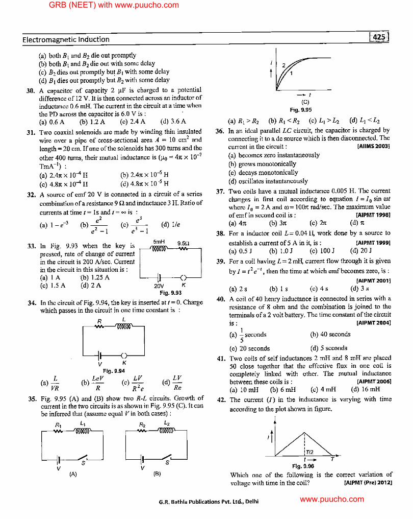
Electromagnetic Induction
(a) both B1 and B2 die out promptly (b) both B 1 and B2 die out with some delay (c) B2 dies out promptly but B1 with some delay (d) B1 dies out promptly but B2 with some delay
30. A capacitor of capacity 2 µF is charged to a potential difference of 12 V. It is then connected across an inductor of inductance 0.6 mH. The current in the circuit at a time when the PD across the capacitor is 6.0 V is :
31.
(a) 0.6 A (b) 1.2 A (c) 2.4 A (d) 3.6 A
Two coaxial solenoids are made by winding thin insulated wire over a pipe of cross-sectional area A = IO cm2 and length= 20 cm. If one of the solenoids has 300 turns and the
other 400 turns, their mutual inductance is (µ 0 = 41t x 10-7
TmA-1):
(a) 2.41tX 10-4H (c) 4.87t X ]0-4 H
(b) 2.41t X 10-5 H ( d) 4.87t X 10-5 H
32. A source of emf 20 V is connected in a circuit of a series
combination of a resistance 9 Q and inductance 3 H. Ratio of
currents at time t = ls and t = oo is : e2 e3
(a) 1-e-3 (b)-- (c) --e2 -1 e
3 - I
33. In Fig. 9.93 when the key is pressed, rate of change of current in the circuit is 200 A/sec. Current in the circuit in this situation is : (a) 1 A (b) 1.25 A (c)I.5A (d)2A
(d) lie
5mH
Fig. 9.93
34. In the circuit of Fig. 9.94, the key is inserted at t= 0. Charge which passes in the circuit in one time constant is
L (a)
VR
R L
L_--111----<( }--~
V K Fig. 9.94
(b) LeV (c) LV R R 2 e
(d) LV Re
35. Fig. 9.95 (A) and (B) show two R-L circuits. Growth of current in the two circuits is as shown in Fig. 9.95 (C). It can be inferred that ( assume equal Vin both cases) :
(A)
L_---j 11--,;,/. s
V (B)
36.
t
-1 (C)
Fig. 9.95
(a) R1 > R2 (b) R1 <R2 (c) L1 > L2 (d) L1 <L2
In an ideal parallel LC circuit, the capacitor is charged by connecting it to a de source which is then disconnected. The current in the circuit : [AIIMS 2003]
(a) becomes zero instantaneously (b) grows monotonically (c) decays monotonically (d) oscillates instantaneously
37. Two coils have a mutual inductance 0.005 H. The current changes in first coil according to equation I = I O sin rot where IO = 2A and Ol= 1007t rad/sec. The maximum value of emf in second coil is : ]AIPMT 1998]
(a) 47t (b) 37t (c) 21t (d) 7t
38. For a inductor coil L= 0.04 H, work done by a source to
establish a current of 5 A in it, is : [AIPMT 19991
(a) 0.5 J (b) 1.0 J (c) 100 J (d) 20 J
39. For a coil having L = 2 roll, current flow through it is given
by I= t 2 e-,, then the time at which emf becomes zero, is :
[AIPMT 2001 I (a)2s (b)ls (c)4s (d)3s
40. A coil of 40 henry inductance is connected in series with a resistance of 8 ohm and the combination is joined to the terminals ofa 2 volt battery. The time constant of the circuit is : [AIPMT 2004I
41.
I (a) - seconds (b) 40 seconds
5 ( c) 20 seconds ( d) 5 seconds
Two coils of self inductances 2 mH and 8 mH are placed 50 close together that the effective flux in one coil is completely linked with other. The mutual inductance between these coils is : ]AIPMT 2006]
(a) 10 mH (b) 6 mH (c) 4 mH (d) 16 mH
42. The current (I) in the inductance is varying with time
according to the plot shown in figure.
,t ' ' ' ' ' 'T/2 1-
Fig. 9.96
Which one of the following is voltage with time in the coil?
T
the correct variation of [AIPMT (Pre) 20121
G.R. Bathla Publications Pvt. Ltd., Delhi
GRB (NEET) with www.puucho.com
www.puucho.com
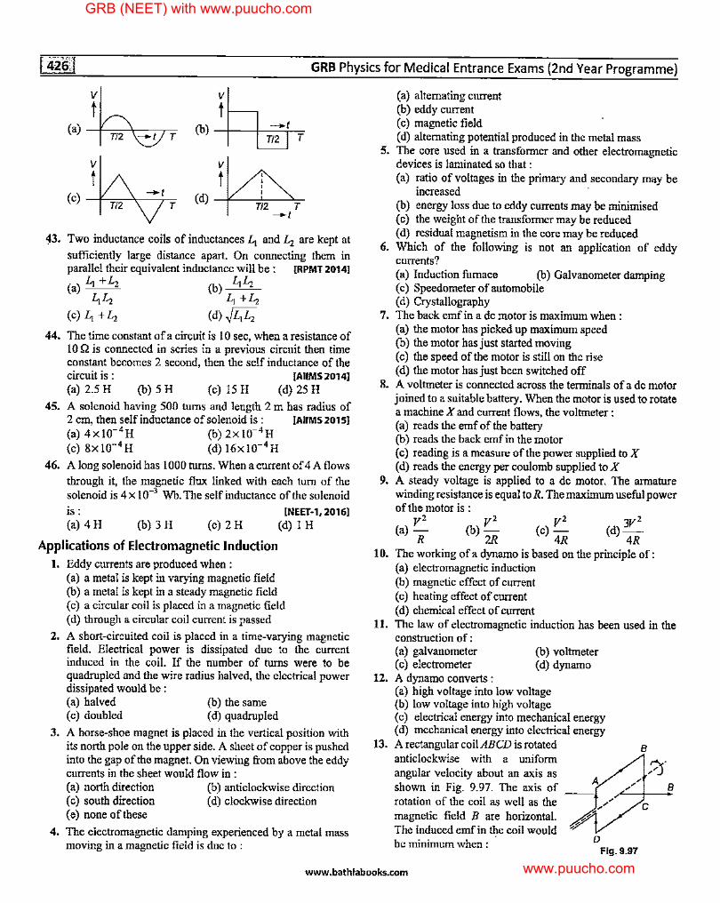
GRB Physics for Medical Entrance Exams (2nd Year Programme)
V
t (a) ----1'----->.---
T/2 ---.1 T
V
t (b -+-I ) --+---+--,-
T/2 T
V
t (d) ----l<':___-=1c-____::,.~
T/2 T ---.1
43. Two inductance coils of inductances Li and L, are kept at
sufficiently large distance apart. On connecting them in parallel their equivalent inductance will be : [RPMT 20141
(a) Li +L2 (b) LiL, LiLz Li +L,
(c) Li +L, (d)~LiL,
44. The time constant of a circuit is IO sec, when a resistance of IO Q is connected in series in a previous circuit then time constant becomes 2 second, then the self inductance of the circuit is : [AIIMS 20141
(a)2.5H (b)5H (c)l5H (d)25H
45. A solenoid having 500 turns and length 2 m has radius of 2 cm, then self inductance of solenoid is: [AIIMS2015l
(a) 4x!0- 4 H (b) 2xl0- 4 H (c) 8xl0-4 H (d) 16xl0-4 H
46. A long solenoid has I 000 turns. When a current of 4 A flows
through it, the magnetic flux linked with each tum of the solenoid is 4 x 10⁻³ Wb. The self inductance of the solenoid
is: [NEET-1, 20161
(a)4H (b)3H (c)2H (d)lH
Applications of Electromagnetic Induction 1. Eddy currents are produced when :
(a) a metal is kept in varying magnetic field (b) a metal is kept in a steady magnetic field ( c) a circular coil is placed in a magnetic field ( d) through a circular coil current is passed
2. A short-circuited coil is placed in a time-varying magnetic field. Electrical power is dissipated due to the current induced in the coil. If the number of turns were to be quadrupled and the wire radius halved, the electrical power dissipated would be : (a) halved (c) doubled
(b) the same ( d) quadrupled
3. A horse-shoe magnet is placed in the vertical position with its north pole on the upper side. A sheet of copper is pushed into the gap of the magnet. On viewing from above the eddy currents in the sheet would flow in : (a) north direction (b) anticlockwise direction ( c) south direction ( d) clockwise direction ( e) none of these
4. The electromagnetic damping experienced by a metal mass moving in a magnetic field is due to :
(a) alternating current (b) eddy current ( c) magnetic field ( d) alternating potential produced in the metal mass
5. The core used in a transformer and other electromagnetic devices is laminated so that : (a) ratio of voltages in the primary and secondary may be
increased (b) energy loss due to eddy currents may be minimised ( c) the weight of the transformer may be reduced ( d) residual magnetism in the core may be reduced
6. Which of the following is not an application of eddy currents? (a) Induction furnace (b) Galvanometer damping (c) Speedometer of automobile (d) Crystallography
7. The back emf in a de motor is maximum when: (a) the motor has picked up maximum speed (b) the motor has just started moving ( c) the speed of the motor is still on the rise ( d) the motor has just been switched off
8. A voltmeter is connected across the terminals of a de motor joined to a suitable battery. When the motor is used to rotate a machine X and current flows, the voltmeter : (a) reads the emf of the battery (b) reads the back emf in the motor ( c) reading is a measure of the power supplied to X ( d) reads the energy per coulomb supplied to X
9. A steady voltage is applied to a de motor. The armature winding resistance is equal to R. The maxinlum useful power
10.
11.
12.
13.
of the motor is : v2 v2
(a)- (b)-R 2R
v2 (c)-
4R (d) 3V2
4R The working of a dynamo is based on the principle of : (a) electromagnetic induction (b) magnetic effect ofcurrent ( c) heating effect of current ( d) chemical effect of current The law of electromagnetic induction has been used in the construction of : (a) galvanometer ( c) electrometer A dynamo converts :
(b) voltmeter (d) dynamo
(a) high voltage into low voltage (b) low voltage into high voltage ( c) electrical energy into mechanical energy ( d) mechanical energy into electrical energy A rectangular coil ABCD is rotated anticlockwise with a uniform angular velocity about an axis as A shown in Fig. 9.97. The axis of __ rotation of the coil as well as the magnetic field B are horizontal. The induced emf in the coil would be minimum when : D
Fig. 9.97
B
,'0" B
www.bathlabooks.com
GRB (NEET) with www.puucho.com
www.puucho.com
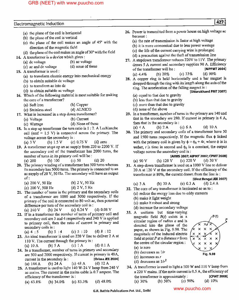
Electromagnetic Induction
(a) the plane of the coil is horizontal (b) the plane of the coil is vertical (c) the plane of the coil makes an angle of 45° with the
direction of the magnetic field (d) the plane of the coil makes an angle of30'with the field
14. A transformer is a device which gives : (a) de voltage (b) ac voltage ( c) ac and de voltage ( d) none of these
15. A transformer is nsed : (a) to transform electric energy into mechanical energy (b) to obtain suitable de voltage ( c) to transform ac into de ( d) to obtain suitable ac voltage
16. Which of the following material is most suitable for making the core of a transformer? (a) Soft iron (b) Copper (c) Stainless steel (d) ALNICO
17. What is increased in a step down transformer? (a) Voltage (b) Current ( c) Wattage ( d) None of these
18. In a step up transformer the turn ratio is I : 2. A Lechlanche cell ( emf = 1.5 V) is connected across the primary. The voltage across the secondary is : (a) 3 V (b) 1.5 V (c) 0.75 V (d) zero
19. A transformer steps up an ac supply from 220 to 2200 V. If the secondary coil of the transformer has 2000 turns, the number of turns in its primary coil will be : (a) 200 (b) 100 (c) 50 (d) 20
20. The primary winding of a transformer has 500 turns whereas its secondary has 5000 turns. The primary is connected to an ac supply of20 V, 50 Hz. The secondary will have an output of: (a) 200 V, 50 Hz (b) 2 V, 50 Hz (c) 200 V, 500 Hz (d) 2 V, 5 Hz
21. The number of turns in the primary and the secondary coils of a transformer are 1000 and 3000 respectively. If the primary of the coil is connected to 80 volt ac, then potential difference per turn of the secondary coil is : (a) 240 V (b) 24 V (c) 0.24 V (d) 0.08 V
22. If in a transformer the number of turns of primary coil and secondary coil are 5 and 4 respectively and 240 V is applied to primary coil, then the ratio of current in primary and secondary coils is : (a) 4 : 5 (b) 5 : 4 (c) 5 : IO (d) 8 : 12
23. An ideal transformer is used on 220 V line to deliver 2 A at 110 V. The current through the primary is : (a)I0A (b)5A (c)IA (d)0.IA
24. In a transformer, number of turns in primary and secondary are 500 and 2000 respectively. If current in primary is 48A, current in the secondary is : JOrissa JEE 20041
(a) 144 A (b) 24 A (c) 48 A (d) 12 A 25. A transformer is used to light 140 W-24 V lamp from 240 V
ac mains. The current in the mains cable is 0.7 ampere. The efficiency of the transformer is : (a) 63.8% (b) 34.0% (c) 83.3% (d) 48.0%
26.
27.
28.
29.
30.
31.
32.
33.
34.
Power is transmitted from a power house on high voltage ac because: (a) the rate of transmission is faster at high voltage (b) it is more economical due to less power wastage (c) the life of the current carrying wire is prolonged ( d) a precaution against the theft of transmission line A stepdown transformer reduces 220V to 11 V. The primary draws 5 A current and secondary supplies 90 A. Efficiency of the transformer will be: [MPPMT 2004]
(a) 4.4% (b) 20% (c) 33% (d) 90% A copper ring is held horizontally and a bar magnet is dropped through the ring with its length along the axis of the ring. The acceleration of the falling magnet is :
[Uttarakhand PMT 20071 (a) equal to that due to gravity (b) less than that due to gravity ( c) more than that due to gravity (d) none of the above In a transformer, number of turns in the primary are 140 and that in the secondary are 280. If current in primary is 4 A, then that in the secondary is : (a)4A (b)2A (c)6A (d)IOA The primary and secondary coils of a transformer have 50 and 1500 turns respectively. If the magnetic flux <j> linked with the primary coil is given by <j> = <l>o + 4t, where <I> is in weber, t is time in second and <l>o is a constant, the output voltage across the secondary coil is :
[AIIMS 2007; AIPMT 2007; CPMT 20081
(a) 90 V (b) 120 V (c) 220 V (d) 30 V A step-down transformer is used on a I 000 V line to deliver 20 A at 120 Vat the secondary coil. If the efficiency of the transformer is 80%, the current drawn from the line is :
[West Bengal JEE 2007]
(a) 3 A (b) 30 A (c) 0.3 A (d) 2.4 A The core of any transformer is laminated so as to : (a) reduce the energy loss due to eddy currents (b) make it light weight ( c) make it robust and strong (d) increase the secondary voltage A uniform but time-varying magnetic field B(t) exists in a circular region ofradius a and is directed into the plane of the paper, as shown in Fig. 9.98. The magnitude of the induced electric field at point P at a distance r from the centre of the circular region: (a) is zero
B (t)
(b) decreases as 1/r ( c) increases as r (d) decreases as llr2
Fig. 9.98
p
A transformer is used to light a I 00 Wand 110 V lamp from a 220 V mains. If the main current is 0.5 A, the efficiency of the transformer is approximately : [CPMT 20081
(a) 30% (b) 50% (c) 90% (d) 10%
G.R. Bathla Publications Pvt. Ltd., Delhi
GRB (NEET) with www.puucho.com
www.puucho.com
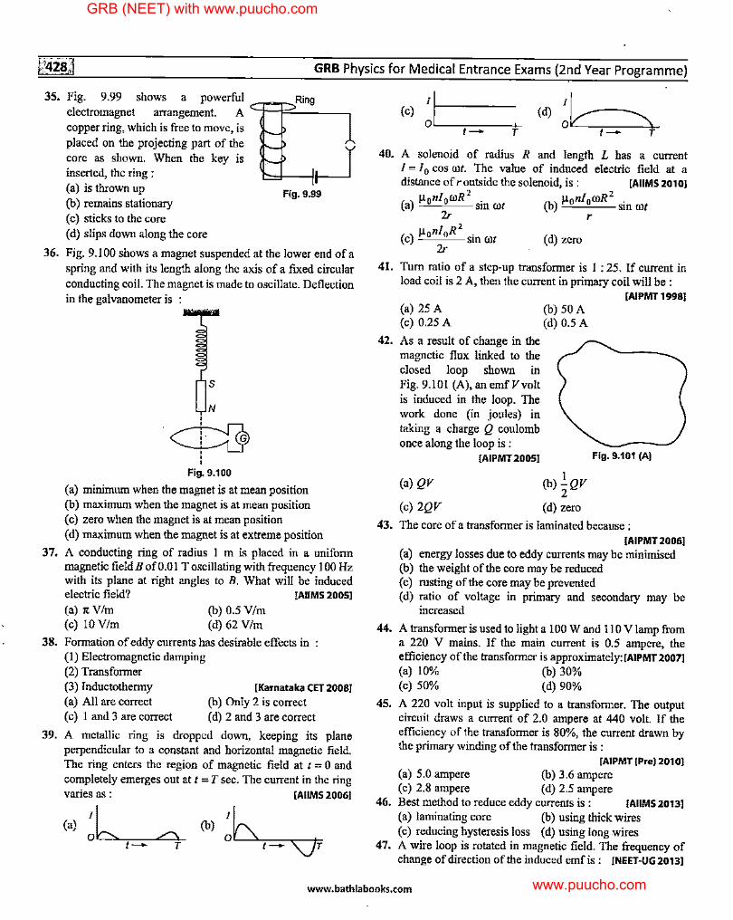
GRB Physics for Medical Entrance Exams (2nd Year Programme)
35. Fig. 9.99 shows a powerful --:i:::RR:'.i'.'.:ng~--, electromagnet arrangement. A -copper ring, which is free to move, is placed on the projecting part of the core as shown. When the key is inserted, the ring : (a) is thrown up (b) remains stationary ( c) sticks to the core (d) slips down along the core
Fig. 9.99
36. Fig. 9.100 shows a magnet suspended at the lower end ofa spring and with its length along the axis of a fixed circular conducting coil. The magnet is made to oscillate. Deflection in the galvanometer is :
37.
38.
39.
,S
N
·~
' ' Fig. 9.100
(a) minimum when the magnet is at mean position (b) maximum when the magnet is at mean position (c) zero when the magnet is at mean position (d) maximum when the magnet is at extreme position
A conducting ring of radius I m is placed in a uniform magnetic field B of 0.01 T oscillating with frequency I 00 Hz with its plane at right angles to B. What will be induced electric field? [AIIMS 20051
(a) it V/m (b) 0.5 Vim (c) IO V/m (d) 62 V/m
Formation of eddy currents has desirable effects in (I) Electromagnetic damping (2) Transformer (3) lnductothermy (a) All are correct ( c) I and 3 are correct
[Karnataka CET 20081
(b) Only 2 is correct ( d) 2 and 3 are correct
A metallic ring is dropped down, keeping its plane perpendicular to a constant and horizontal magnetic field. The ring enters the region of magnetic field at t = 0 and completely emerges out at t = T sec. The current in the ring varies as : [AIIMS 20061
(a) ~'Ll--"~-~/""'\'-'-t - T
(b)~~
(c) [~-----OL-----,-----±-
t - T
(d) ~k--~ t- T
40. A solenoid of radius R and length L has a current I =IO cos rot. The value of induced electric field at a distance ofroutside the solenoid, is : [AIIMS 20101
( ) µ 0nlomR2
. (b) µ 0 n/0 ooR 2 • a '-"-''----- sm rot '-"-''--- sm rot
2r r
(c) µonloR2
sin rot (d) zero 2r
41. Tum ratio of a step-up transformer is 1 : 25. If current in load coil is 2 A, then the current in primary coil will be :
[AIPMT 19981
42.
43.
44.
45.
46.
47.
(a) 25 A (c) 0.25 A
As a result of change in the magnetic flux linked to the closed loop shown in Fig. 9.101 (A), an emf Vvolt is induced in the loop. The work done (in joules) in taking a charge Q coulomb once along the loop is :
(b) 50 A (d) 0.5 A
[AIPMT 20051 Fig. 9.101 (A)
(a) QV (b) ..!_ QV 2
(c) 2QV (d) zero
The core of a transformer is laminated because : [AIPMT2006l
(a) energy losses due to eddy currents may be minimised (b) the weight of the core may be reduced (c) rusting of the core may be prevented (d) ratio of voltage in primary and secondary may be
increased
A transformer is used to light a 100 W and 110 V lamp from a 220 V mains. If the main current is 0.5 ampere, the efficiency of the transformer is approximately: [AIPMT 20071
(a) 10% (b) 30% (c) 50% (d) 90%
A 220 volt input is supplied to a transformer. The output circuit draws a current of 2.0 ampere at 440 volt. If the efficiency of the transformer is 80%, the current drawn by the primary winding of the transformer is :
[AIPMT (Pre) 201 OJ (a) 5.0 ampere (b) 3.6 ampere (c) 2.8 ampere (d) 2.5 ampere Best method to reduce eddy currents is : [AIIMS 2013)
(a) laminating core (b) using thick wires (c) reducing hysteresis loss (d) using long wires A wire loop is rotated in magnetic field. The frequency of change of direction of the induced emf is : [NEET-UG 2013)
www.bathlabooks.com
GRB (NEET) with www.puucho.com
www.puucho.com
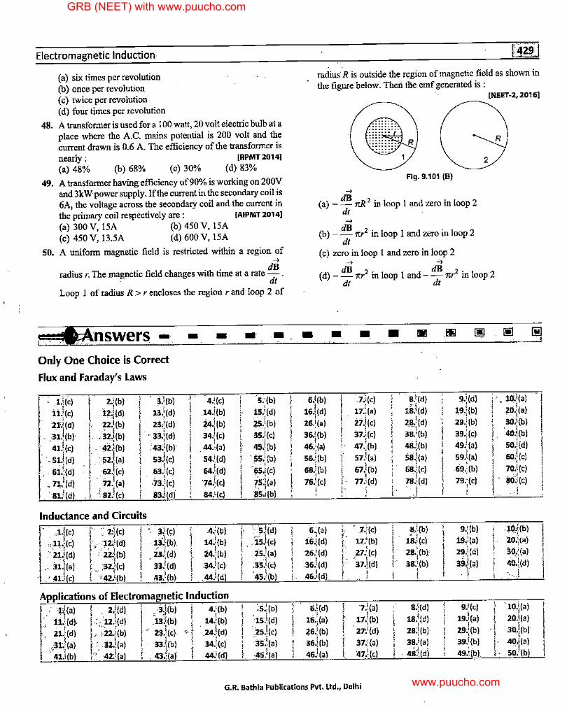
Electromagnetic Induction-
(a) six times per revolution (b) once per revolution ( c) twice per revolution ( d) four times per revolution
48. A transformeris used for a 100 watt, 20 volt electric bulb at a place where the A.C. mains potential is 200 volt and the .current drawn is 0.6 A. The efficiency of the transformer is nearly : [RPMT 20141 (a) 48% (b) 68% (c) 30% (d) 83%
49. A transformer having efficiency of90% is working on 200V and 3kWpower supply. If the current in the secondary coil is 6A, the voltage across the secondary coil anrl the current in the primary coil respectively are: [AIPMT 20141 (a) 300 V, 15A (b) 450 V, 15A (c) 450 V, 13.5A (d) 600 V, 15A
SO. A uniform magnetic field is restricted within a region of ..., radius r. The magnetic field changes with time at a rate dB .
. dt Loop I of radius R > r encloses the region r and loop 2 of
1tAnswers • Only One Choice is Correct
Flux and Faraday's Laws
. 1.)(i:) z.\(b) 3.1(b)
11.l(c) . I 13.l(d) .12.,(d)
21.j(d) zz,l(b) z:t!(d) -~ ' . • 33.\(d) .. ,31.,(b) ,32.;(b)
. 41.\(c) . '
42-j(b) .'43)(b)
53.i(c) ,51.l(d) . :52.<(a) - '(
62.\ic) !
63.\ic) .. 61.,(d) I · 72.1(a) l ' ' • 7~ •• (d) •73.!(c)
. 81.!(d) \sz.l(cl ! s3J(dl
Inductance and Circuits . ·· ,1.!(c) ~, ,-' ., . l
•. 3:l(c) . 1 I . z,11c>
·l .,11.1(c) ,, ··12,l(d) · ,13,.(b)
!'tz:d(bl '23.!(d) ;21.l(d) . 1 ,· 31.1(•) r ,, :~z.,(c) 33.l(d)
! 0 42.i(b) 43.i(b) · 41.i(c) !
- -4.:(c)
,14.l(b) ' 24.j(b)
' ! 34.j(C)
I . 44.l(a) 1 54.1(d) i I
I 64.:(d)
74.!(c) i ' 84.'(c) '
l •1':(b)
14.i(b)
24.\ib)
34.!(c) I ' I 44.l(d)
Applications of Electromagnetic Induction : 1,1(•) ! : z)(d) _ ·3J(b) r 4.'(b)
.· I " l 14.i(b) . .11.,(d), .; , 12.\(d) 13 •. (b)
'. i1.!(d) .,,.,_ - r ..
' 23.l(c) < l . I .
, ;22.)(b) 24.;(d)
!,31:!(•) i . 33.j(b) 34l(c) : 32.\(a)
l ,," 42;i(a) 41.l(b) J • 43.:(a) 44.'(d)
- -'s:,(bl
I 15.!(d)
zs.i(bl
' . '
! 35.l(c)
45.i(b) L I
· ss)(bl ' ' i ,. "I
I 0
65.!(c)
is:ha)
I '). ! 85.,(b)
j' s.j(dl
I. is.i(c) . I } .25. (a)
! iis.l(c)
·4s.!(bl I
:s.!(b)
'1s.l(d) : I ,25.,(c) 3S.i(a) ' I
I . ' 45.!(a)
I I
I I I l l
I ' ,
' I l
! i.
I
' ' I I I
! l
radius· R is outside the region of magnetic field as shown in the figure below. Then tlie emf generated is :
[NEET-2, 20161 -----
Flg.9.101 (B) ...,
(a) - dB ,cR2 in loop I and zero in loop 2 dt . ...,
(b) - dB nr2 in loop I and zero in loop 2 dt
( c) zero in loop I and zero in loop 2 ..., 4
R
2
( d) - dB 1tr2 in loop I and - dB 1tr2 in loop 2 dt dt
- • • • Ill!
6.l(b) ' 7.l(c) ' 8/<(d) ;
!i.\(d) '. 10.i(a) I I J I
1s.l1d, ' 19.l(b) . I
16.:(d) 17.,(a) I I 20.1(a)
27.l(c) zs.!(d) 26.l(a) ! : 29.;(b) 30;\(b)
38:i(b) I 40.\(b) 36.j(b) 37.i(c) 39.!(c) ' 47\b) i 48.i(b) 46.1(a)
I soJ(dl 49.';(a) I i 57.l(a) l I
S9J(a) 60:i(c) 56.!(b) ;
:::ll~t ' ' I 66.!(b) ! 67.i(b) '
., ; 69.;(b) l 70.l(c)
76.!(c) ' I I, so:l(c) f 77.!(d) I 79.;(c)
i ! i l .I ' I ' I
6.;(a) 1\ .7.j(c) ' .s.i(bl I 9.;(b) I .10:i(b) I • I I '
.. , 16~(d) t• 17.'(b) I 18J(c) I i9.i(a) l
• I
l 20,;(a)
' 28.l(b) 29.i(d) 26.'(d) I 27.'(c) 30i(a) l l ' l . 0
37.!id) 39:J(a) . ,1
36/(d) 3s;1(bl I 40.i(d)
46.l(d) I ' ' l I I
I I I '
6.j(d)
l· 7.i(a) 8;\(d) I 9.'(c) i 10.\(a)
' 1si(d) )
19.\(a) 16._,(a) 17.,(b) I J 20,l(a)
21}(d) zs)(bl I
·30,!(b) 26.1(b) i 29;:(b)
l ' I 38.l(a) 39.l(b) I
36,!(b) 37.1(a) I 40l(a)
46.l(a) I. 47.!(c) . 411:l(d) ! 49.l(b) •I
! ,· SO:'(b)
G.R. Bathla Publications Pvt. Ltd., Delhi
I !
I
GRB (NEET) with www.puucho.com
www.puucho.com
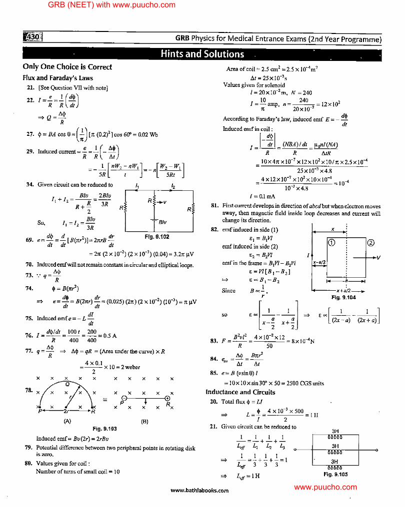
GRB Physics for Medical Entrance Exams {2nd Year Programme)
· Hints and Solutions . · . . · Only One Choice is Correct
Flux and Faraday's Laws
21. [See Question VII with note]
22. I=!.=.}_ (d$) R R dt
=> Q = t.$ R
27. $= BA cos 0=(;}" (0.2)2 ]cos 60"= 0.02 Wb
29. Induced current=!.=.}_ (- M) R R t.t
=-5~ [ nW, ~nw, ]=-n[W\~1W1]
34. Given circuit can be reduced to
So,
I I _ Blu _ 2B/u
1+ 2------R+!!. 3R
2 Blu
11 =l2 =-3R
,, R -+-V
R
d~ d 2 dr Fig. 9.102 69. e=....!=-[B(1tr)]=21trB-
dt dt dt
,,
R
= 27t (2 X 10⁻²) (2 X 10⁻³
) (0.04)= 3.27' µV
70. Induced emf will not remain constant in circular and elliptical loops.
73. ·.· q= t.$ R
74. $ = B(1tr')
e= d$ = B(21tr) dr = (0.025) (21t) (2 x 10⁻²) (10-3) = It µV dt dt
di 75. Induced emf e = - L -
dt
76_ I= d$/dt = 100 t = 200 = 0_5 A R 400 400
77. q = t.$ => t.$ = qR = (Area under the curve) x R R
78.
X X X
4 X 0.J =--X10=2weber
2 X X X X
1:7:\ X X
- 0 p X X X p 2r R
(A) Fig. 9.103
Induced emf= Bu(2r) = 2rBu
X X
X X
i X X
(B)
X
X 0 Rx
79. Potential difference between two peripheral points in rotating disk is zero.
80. Values given for coil :
Number of turns of small coil = I 0
Area of coil= 2.5 cm2 =2.5 x 10⁻⁴m2
t.1 = 25x10-3s Values given for solenoid
1=20x10-2 m, N =240
J=10
, n 240
=12x102
" amp 2ox10-2
According to Faraday's law, induced emf E = - d$ dt
Induced emf in coil :
I J-:; I (NBA)/ dt = µo"l(NA)
R R t.tR
10X41t X 10-7 X )2X 102 X 10/!t X 2.5 X 10⁻⁴
25 X 10-3 X 4.8
4 x12x10-7 x1o'x10x10-4 = 10
..,
10-3 x4.8
l=0.lmA
81. First current develops in direction of abed but when electron moves away, then magnetic field inside loop decreases and current will change its direction.
82. emfinducedinside(l) x
e1 = B1V/ emf induced in side (2)
G)
e2 = B2V/ I -+-+-'V emf in the frame= B1Vl- B2Vl x-a/2
=>
Since
E=V/[B 1-B2] eoc:B 1 -B2
I B«-,
r
1+---a-i
'+---x+a'12----.. Fig. 9.104
so ·~[-1 ___ 1_] =>
x-~ x+1 •~[(2x~a)- (2x~a)]
83_ F = B2u/
2 4 x 10-
2 x 12 = 8 x 10_,N
R 50
t.$ B1tr' S4. e,,, = t.t =At 85. e= B (usin0) I
= 10 x 10 x sin 30" x 50 = 2500 CGS units
Inductance and Circuits 20. Total flux$ = LI
=> L = .P_ = 4 X 10-3
X 500 = l H I 2
21. Given circuit can be reduced to
I I I 1
I -=-+-+-L,ff L, L, L,
0
1 1 I 1 => -=-+-+-=!
Leff 3 3 3
3H
~: => L,ff=IH Fig. 9.105
i 0
www.bathlabooks.com
GRB (NEET) with www.puucho.com
www.puucho.com
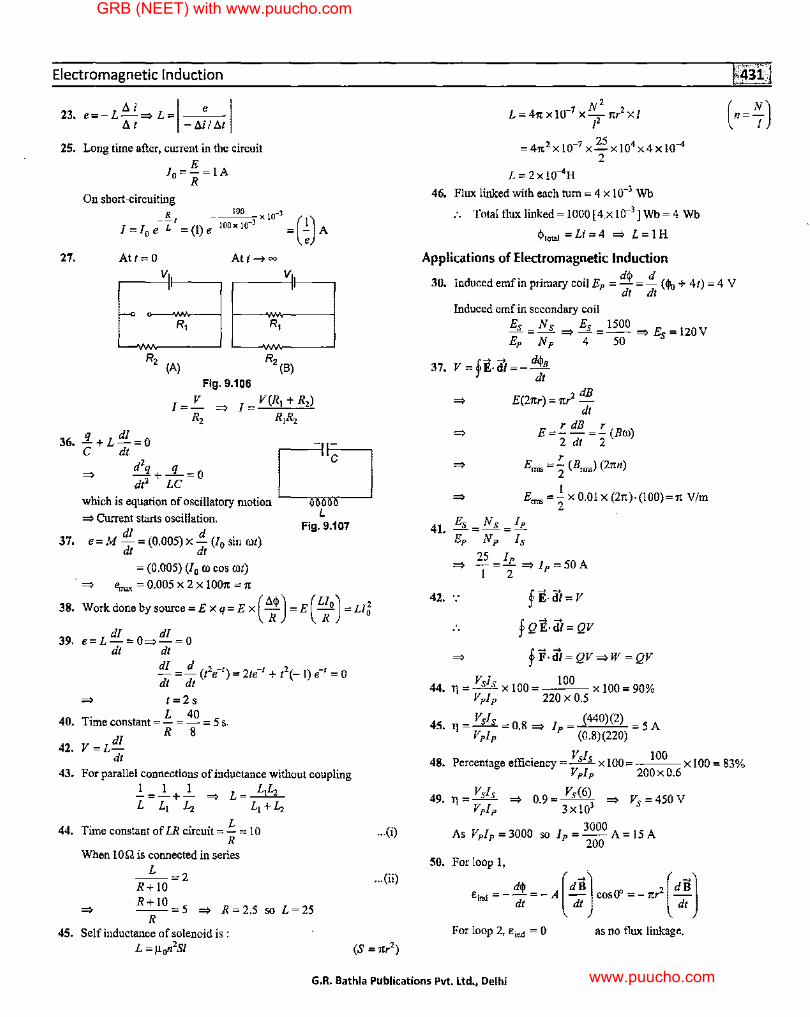
Electromagnetic Induction
23. e=-L~=> L=I e I IH -MIM
25. Long time after, current in the circuit E
10 =-=IA R
27. Att= 0 Att~oo v,,
I'
.. R,
(A)
Fig, 9.106
v,, I'
I=!_ => I R2
V(R1 + R,)
R,R,
36. !i+L di =O
0_
C • C
=> d'q +...!l_=O dt2 LC
which is equation of oscillatory motion ~ Current starts oscillation. L
37. e=M di =(0.005)x!!.(J0 sinrot) Fig. 9,107
dt dt
= (0.005) (10 ro cos rot) => '\mx = 0,005 X 2 X 100'/t = 1t
38. Work done by source= Ex q= Ex ( ~$) =E( L~o) =Llg
dl dl 39, e=L-=0=>-=0
dt dt
dl = !!_ (t2e-') = 2te-1 + t'(- I).-, = 0 dt dt
=> t=2s
40 T. L 40
• tme constant=-=-= 5 s.
42. V=Ldl dt
R 8
43. For parallel connections of inductance without coupling
2_=_.!._+_.!._ => L= L,Lz L L, L, L,+Lz
44. Time constant of LR circuit=!::.= 10 R
When 10.Q is connected in series
_L_=2 R+lO
-R+I0=5 => R=2,5 so L=25 R
45. Self inductance of solenoid is : L =µ,n 2S/
,,.(i)
... (ii)
N' L = 4n x10-1 x-
2 nr2 xi
I
= 4n 2 X 10-7 X 25 X 104 X4 X 10-4 2
L = 2x 10⁻⁴H
46. Flux linked with each tum= 4 x.10-3 Wb
:. Totalfluxlinked=l000[4xl0-3]Wb=4 Wb
$.,"' =Li=4 => L=lH
Applications of Electromagnetic Induction
30. Inducedemfinprimarycoi!Ep = d$ =!!_ (<I\,+ 41)=4 V dt dt
Induced emf in secondary coil
Es =Ns => Es =1500 => Es=IZOV Ep Np 4 50
37. V='E-iu=-d$. r d1
=> E(2nr) = nr2 dB dt
r dB r => E=--=-(Bro)
2 dt 2 r
=> E= =- (B=) (2nn) 2 1
=> E==-X0.0lx(21t)·(l00)=1tV/m 2
4 E8 =N8 =Ip 1.
42.
Ep Np ls
25 I => -=1=>fp=50A
2 .~ ~ y E-dl= V
£ ~ ~ y QE·dl= QV
VI 44. l] = _§_£_ X 100
Vplp
fi1-iu = QV =>W = QV
100 ---x100=90% 220 X 0.5
VI 45. lJ = ....L£. = 0,8 =>
Vplp I = (440)(2) = 5 A
P (0.8)(220)
. VI 100 48. Percentage efficiency = _§___£__ x 100 = --- x 100 = 83%
Vplp 200x0.6
Vsls Vs(6) 49. TJ =-- => 0.9=--3 => Vs =450V
Vplp 3xl0
3000 As Vplp=3000 so lp=--A=l5A
200
50. Forloop I,
E·ru1 = - d$ = - A [dBJ cosO" = - nr2 [dBJ ' dt dt dt
For loop 2, Emd = 0 as no flux linkage.
G.R. Bathla Publications Pvt. Ltd., Delhi
GRB (NEET) with www.puucho.com
www.puucho.com
GRB Physics for Medical Entrance Exams {2nd Year Programme)
Directions : These questions consist of two statements each printed as Assertion and Reason. While answering these questions you are required to choose aey one of the fol/owJngfour responses: (a) If both Assertion and Reason are true and the Reason is the
correct explanation of the Assertion. (b) If both Assertion and Reason are true and the Reason is not
a correct explanation of the Assertion. ( c) If Assertion is true but Reason is false. (d) If both Assertion and Reason are false.
1. Assertion : Magnetic flux is a vector quantity. Reason : Value of magnetic flux cannot be negative.
2. Assertion : Change in magnetic flux w.r.t. time produces an induced emf. Reason : Faraday established induced emf experimentally.
3. Assertion : The direction of induced emf is always such as to oppose the change that causes it. Reason : The direction of induced emf is given by Lenz's law.
4. Assertion : An emf is induced in a closed loop where magnetic flux is varied. The induced electric field is not a conservative field.
Reason : For induced electric field, the line integral f E • iii aronnd a closed path is non-zero. [AIIMS 20061
5. Assertion : It is more difficult to push a magnet into a coil with more loops. Reason : This is because emf induced in each current loop resists the motion of the magnet. [AIIMS 20061
6. Assertion : Eddy current is produced in any metallic conductor when magnetic flux is changed around it. Reason : Electric potential determines the flow of charge.
7. Assertion : Acceleration ofa magnet falling through a long solenoid decreases. Reason : The induced current produced in a circuit always flow in such direction that it opposes the change or the cause that produces it.
8. Assertion : A conducting rod is moving in a uniform magnetic field such that the length of the rod, its velocity and the magnetic field are mutually perpendicular, then, an emf will be induced between the ends of the rod. Reason : As the rod moves as stated above, free electrons in it will experience magnetic force towards an end of the conductor.
9. Assertion : When a coil is rotated in a uniform magnetic field about an axis perpendicular to the field, emf is induced in it which is maximum for the orientation of the coil in which magnetic flux through the coil is zero. Reason : In an electric generator, electrical energy is generated by rotating a coil in a magnetic field.
10. Assertion : In the phenomenon of mutual induction, self induction·of each of the coil persists. Reason : Self-induction arises when strength of current in one coil changes. In mutual induction, current is changing in both the individual coils. [AIIMS 2006, 071
'·i 11. Assertion : An electric motor will have maximum efficiency
when back emf becomes equal to half of applied emf. Reason : Efficiency of electric motor depends only on magnitude of back emf. [AIIMS 20081
12. Assertion : Two identical coaxial circular coils carry equal currents circulating in same direction.
If coils approach each other, the current in each coil decreases.
I I
Fig. 9.108
Reason : When coils approach each other, the magnetic flux linked with each coil increases.
13. Assertion : If we use a battery across the primary of a step up transformer, no voltage is obtained across secondary. Reason : Battery gives a steady current.
14. Assertion : If current changes through a circuit, eddy currents are induced in nearby iron plate. Reason : Due to change of current, the magnetic flux through iron plate changes.
15. Assertion : Only a change of magnetic flux with time, will maintain an induced current in the coil. Reason : The presence of a large magnetic flux will maintain an induced current in the coil. [AIIMS 19991
16. Assertion : The coils in the resistance boxes are made by doubling the wire. Reason : When two coils are wound on each other, the mutual inductance is zero.
17. Assertion : Self-inductance is called the inertia of electricity. Reason : In a L-R circuit, the inductor opposes any change in current.
18. Assertion : A bar magnet is dropped into a long vertical copper tube. Even with the effect of air resistance being negligible, the magnet still attains a constant terminal velocity. Now, if the tube is heated, the terminal velocity also increases. Reason : The tenninal velocity does not depend upon the eddy currents produced in the magnet.
19. Assertion : A piece of copper and a similar piece of stone are dropped simultaneously from a height near the earth's surface. Both will touch the ground at the same time. Reason : There is no effect of the earth's magnetic field on the motion of falling bodies.
20. Assertion : The mutual inductance of two coils is doubled if the self-inductance of the primary and secondary coil is doubled. Reason : Mutual inductance M ~~Li L,.
www.bathlabooks.com
GRB (NEET) with www.puucho.com
www.puucho.com
Electromagnetic Induction
[
21. Assertion : The minimum inductance that can be obtained by combining two inductors of 3 H and 6 H is 2 H. Reason : Minimum inductance is obtained when the inductors are connected in parallel.
22. Assertion : An artificial satellite with metallic surface is moving about the earth in a circular orbit. A current is induced when the plane of orbit is inclined to the plane of equator. Reason : The satellite cuts the magnetic field of earth.
23. Assertion : Inductance coil are made of copper. Reason : Copper has a very small ohmic resistance.
24. Assertion : The direction of the induced electric field is always perpendicular to the direction of the changing magnetic field. Reason : The induced electric field is a non-conservative field.
25. Assertion : An emf is induced in a long solenoid by a small bar magnet that moves while totally inside it along the solenoid axis. Reason· : As the magnet moves inside the solenoid, the flux through individual turns of the solenoid does not change.
26. Assertion : If a charged particle is released from rest in a time varying magnetic field, it moves in a circle, Reason : In a time varying magnetic field, conservative electric field is induced,
27. Assertion : A system cannot have mutual inductance without having self inductance, Reason : If mutual inductance of system is zero, its selfinductance must be zero.
28. Assertion : Time dependent magnetic field generate non-conservative electric field, Reason : Direction of electric field generated from time varying magnetic field does not obey Lenz's law.
29. Assertion : When two coils are wound on each other, the mutual induction between the coils is maximum. Reason : Mutual induction does not depend on the orientation of the coils.
30. Assertion : At any instant, if the current through an inductor is zero, then the induced emf may not be zero. Reason : An inductor tends to keep the flux constant.
31. Assertion : The possibility of an electric bulb fusing is higher at the time of switching ON and OFF.
Reason : Inductive effects produce a surge at the. time of switch-off and switch-on. [AIIMS 2003]
11t:Answers - - Ei3 s lei
1._(d) 2. (b) 3. (b) 4:(a) 5-;(a) 11:(c) 12.'(a) 13. (a) 14.'(a) 15.,(c) 21.'.(a) 22.,(a) 23. (a) 24. (b) 25-'.(d) 31.,(al 32. (cl 33,(a) 34. (al 35. {di
32. Assertion : The quantity i'. possesses dimension of time. R
Reason : To reduce the rate of increase of current through a solenoid, we should increase the time constant (i.e., IJR).
33. Assertion : A small magnet takes longer time in falling in a hollow metallic tube without touching the wall. Reason : There is opposition of motion due to production of eddy currents in metallic tube, [AIIMS 201 OJ
34. Assertion : When an aluminium disc is spun between the magnetic poles, it quickly comes to halt. Reason : Eddy currents are produced in the disc, these set up a magnetic field which pulls on the poles and opposes the motion.
35. Assertion : Making or breaking of current in a coil produces no momentary current in the neighbouring coil of another circuit. Reason : Momentary current in the neighbouring coil of another circuit is an eddy current.
36. In shown circuit, switch is closed att = 0. R
Assertion : At t = 0, current E
through battery I= - and at 2R
t = =, current through battery
will be/= E_ R
E Fig. 9.109
Reason : At t = 0, inductor will behave like open circuit
and at I = =, inductor will behave like short circuit.
37. Assertion : Magnetic flux through a closed surface is zero, Reason : Magnetic field lines form closed loop.
[AIIMS 20151
38. Assertion : Induced electric field lines form closed loop in space. Reason : Induced electric field lines don't originate and ends at charge particle, [AIIMS 2015]
39. Assertion : In L-R circuit, if higher value of Lis taken then it will take more time to reach steady state value of current. Reason : For higher value of L, back emf is larger:
[AIIMS 2015]
40. Assertion : In a step down transformer, value of voltage in secondary coil is less than in primary. Reason : Linked magnetic flux in secondary is less than in primary, [AIIM5 2016 (Morning)]
l!!!!l !!!ii i!!ll ~ [Bl I!!! I@ ~ EJ 6. (b) 7. (a) 8°'(a) 9, (b) 10 .. (a)
16. (c) 17. (a) 18. (c) 19.,(d) 20.,(a)
26. (d) 27. (c) 2s:,(c) 29.,(c) 30. (b)
36, {a) 37.'(al 38. (al 39. (al 40. {al
G.R. Bathla Publications Pvt. Ltd., Delhi
GRB (NEET) with www.puucho.com
www.puucho.com