Embed Size (px)
Citation preview
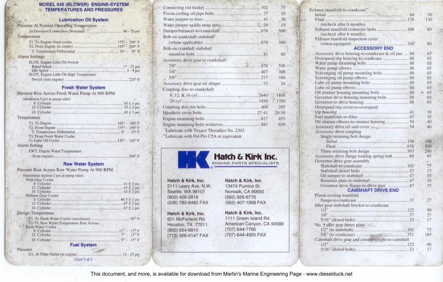
MODEL 645 (BLOWER) ENGINE-SYSTEMTEMPERATURES AND PRESSURES
Lubrication Oil SystemPressure A: Normal Operating Temperature
AlGovernorConnection(Nominal) 40 - 71)psiTemperature
TI, To Engine (fromcooler .. 175' - 200"FT2. FromEngine(10 cooler) j 95' - 200"FT. Temperature Differential ~ 20° - 25° f"
Alarm SettingsELOS.EngineLubeOil SwitchRated Speed 17-21 psiIdleSpeed 5 - 9 psi
ELOT.EngineLubeOil HighTemperatureSwitch (imoengine) 220"F
Fresh Water SystemPressure Rise Across Fresh Water Pump At 900 RPM
(minimum 0 psi 31 pump inlet)8 Cylinder 45 ± 3 psi12 Cylinder 53± 3 psi16 Cylinder 45 ± 3 psi
TemperatureTI. To Engine 165' - t80" FT2. FromEngine 175' - 190' FT. Temperature Differential go _ 15° F
T3.From FreshWaterCoolerTo LubeOilCooler 150' - 165' F
Alarm Selling ,EWT.EngineWaterTemperature(fromengine) 200' F
Raw Water SystemPressure Rise Across Raw Water Pump Al 900 RPM
(maximum suction-2 psi at pump inlet)WuhGeMCooler
8 Cylinder 41 ± 2 psi12 Cylinder , 43 ± 2 psi16 Cylinder .43 ± 2 psi
Without Gear Cooler '8 Cylinder 46.5 ± 2 psi12 Cylinder 47± 2 psi16 Cylinder " 47± 2 psi
Design Temperature •TI. To FreshWorer Cooler(maximum). .. 85· F1'2-TI. RawWaterTemperatureRiseAcross
FreshWaterCooler
I~§~::~~~;:::::::::::::::::::::::::::::::::::::::::::::::::::::::::::::::::::..I~:::~:~16 Cylinder 9' - 15' F
Fuel SystemPressure
GI. A. FilterOutlet(10 engine) 12- 25 p~iCard30f3
Connecting rod basket ......................... :......... ".............. 102 75 iI: Exhaust manifold-to-crankcase"Piston cooling oil pipe bolts .............. <: .......................... 27 20 , Initial ........................................... :<.~................... 68 50Water jumper-to-liner ................................. c ••••••••••....•••• 4 I 30 , Final ....................................................... :................ 176 130Water jumper saddle strap nUIS ...•.................................. 20 15 {, (recheck after 6 months)Damper/balancer-to-crankshaft ......... ~....................... ,. 678 500 Exhaust manifold connector bolts .......................... 108 80,,-. (recheck after 6 months)Bolt-on crankshaft stubshaft' . ~
Exhaust manifold inspection cover(where applicable) .................................................. 678 . 500 J. '. ,.~
'1 t' I(when equipped) ................................................ 108 80
Bolt-on cranshaft stubshaft I' ACCESSORY ENDretention bolts ............................................... :........... 81 60 ~, Accessory drive housing-to-crankcase & oil pan .... 88 65
Accessory drive gear 10 crankshaft- Overspeed trip housing-to-crankcase ....................... 88 657/8" ........................................................... .!;...........678 500 Water pump mounting bolts ..................................... 88 65
Water pump elbows ................................................. 88 653/4" ......................................................................... 407 300 Scavenging oil pump mounting bolts ....................... 88 65
• 5/8" ......................................................................... 217 160 Scavenging oil pump elbows ............ " ..................... 88 65Accessory drive gear oil slinger .................. ~................. 33 24 Lube oil pump mounting bolts ................... ~............ 88 65Coupling disc-to-crankshaft ,. " Lube oil pump elbows .............................................. 88 65 ..
8, 12.& 16 cyl """""""''''''''''''''''''''',,"'''''''''''''' 2440 1800,. Oil strainer housing mounting bolts ......................... 88 • 65
Governor drive housing mounting bolts .................. 88 6520 cyl ................................................................... 1830 1350 " Governor-to-drive housing ....................................... 88 65
Coupling disc rim bolts ............................................... 400 295 , Overspeed trip cover-ro-overspeedHandhole cover bolts ............................................... 27-41 20-30 tl trip housing .............................................................. 41 30Engine mounting bolts ................................................ 6 I7 455 Fuel manifolds-to-Iilter ............................................ 47 35
Engine mounting bolts wlsleeves ................................ 881 650 I Oil strainer elbows-to-strainer housing ""'.""""""'" 54 40Accessory drive oil seal cover •...,. ........................... 54 40
'Lubricate with Texaco Threadtex No. 2303 ; 1 Accessory drive coupling"Lubricate with Fel-Pro C5A or equivalent Single retaining bolt design
Initial ............................................................ 136 lOOFinal ............................................................. 678 500
Three retaining bolt design ............................... 393 290l1akh le Kirk Inc.
I I'Accessory drive flange locking spring bolt .............. 88 65
ENGINE PARTS SPECIALISTS .' Governor drive gear assembly11> Stubshaft-to-crankcase ...................................... 102 75
Stubshaft dowel bolts .......................................... 23 17Oil jurnper-to-stubshaft ............... _....................... 47 35
Hatch & Kirk, Inc. Hatch & Kirk, Inc. Retainier plate-to-stubshaft ................................. 47 355111 Leary Ave. N.W. 13474 Pumice SI. Governor drive flange-to-drive gear ................... 47 35Seattle, WA 98107 Norwalk, CA 90650 , CAMSHAFT DRIVE END(800) 426-2818 (562) 926-8776 Piston cooling manifold(206) 782-6482 FAX (562) 407-1958 FAX . flangc-ro-crankcase ............................................. 37 27
Idler gear srubshaft bracket-to-crankcase
Hatch & Kirk, Inc. 112".................................................................... 122 90Hatch & Kirk, Inc. 3/8" ...................................................................... 37 27601 McFarland Rd. 1111 Green Island Rd. 5/16" (dowel bolts) .............................................. 23 17Houston, TX 77011 American Canyon, CA 94589 No. ~ idler gear thrust plate(800) 654-8910 (707) 644-7766
~.: 1/2" (to stubshaft) .............................................. 102 75(713) 926-4147 FAX (707) 644-4920 FAX 5/8" (to crankcase) ............. , .............................. 25 I 185
Camshaft drive gear and counterweigbt-to-carnshaft1/2" .................................................................... 122 905/16" (dowel bolts) .............................................. 23 17
This document, and more, is available for download from Martin's Marine Engineering Page - www.dieselduck.net

\ MODEL 645 (TURBO) ENGINE-SYSTEMTEMPERATURES AND PRESSUijES
Lubrication Oil SystemPressure At Nonnai Operating Temperature
At Governor Connection (nominal) ..................•............... 60 - I()() psiTemperature
TI. To Engine (from cooler) 175°· 195° FT2, From Engine (to cooler) 195°· 220° F
T. Temperature Differential _.: •..... 20°- 25° FAlarm Settings
ELOS, Engine Lube Oil SwitchRated Speed .............................•................................ 26- 30 psiIdle Speed ..................•.................................................... 10-14 psi
L02, Soak Back Pump Low Oil Pressure • .(rising pressure) 10 pSI
ELOT, Engine Lobe Oil High TemperatureSwitch (into engine) 220° F
Fresh Water SystemPressure Rise Across Fresh Water Pump At 900 RPM
(minimum 0 psi at pump inlet}8 Cylinder.. .. 47 ± 3 psi12 Cylinder 48 ± 3 psi16 Cylinder 55 ± 3 psi20 Cylinder 55 ± 3 p$i
TemperatureTI, ToEngine 165°· 180°11T2. From Engine 175°· 190° F
T. Temperature Differential 8°_ 15° FT3, From Fresh Water CoolerTo LubeOilCooler 150°· 165°F
Alarm SettingEm. Engine Water Temperature(from engine) 200° F
TemperatureT, Oil to Water 25° F Max.
RawWater SystemPressure Rise Across Raw Water Pump AI goo RPM
(maximum suction-2 psi at pump inlet)With Gear Cooler
8 Cylinder 43 ± 2 psi
1~ g~::~~~~:::::::::::::::::::::::::::::::::::::::::::::::::::::::::::::::::::::j~~~~::20 Cylinder 32 ± 2 psi
Withtnn Gear Cooler8 Cylinder 47 ± 2 psi12 Cylinder ~: 47 ± 2 psi16 Cylinder " 41 ± 2 psi20 Cylinder 32 ±2 psi
Design TemperatureTI, To Fresh Water Cooler (rnex.) " 85° f:T2-T I, Raw Water Temperature Across
Fresh Water Cooler8 Cylinder 7°· 13° F
:~g~n~~~~:::::::::::::::::::::::::::::::::::':::::'::::::~:.::::::::::::::::::~:::~:~20 Cylinder 17°· 23° F
Fuel SystemG I, At Filter Outlet (to engine) 12- 25 psi
N'm Ft·LbsCamshaft drive housing-to-crankcase 88 65Oil manifold-to-oil manifold 50 37Oil manifold-to-crankcase : 43 3,2Oil slinger-to-crank shaft gear : 23 17Oil retainer-to-camshaft drive housing " 41 3(J
TURBO ENGINES ONLY
Turbocharger mounting bolts-3/4" " " " 238 1751/2" 88 65
Air ducts-to-turbocharger " 81 60Air ducts-to-crankcase .. " 88 65Auxiliary drive-to-turbocharger
3/8" ..............................................................•............ 32 241/2" ...................•........................................ ~ 88 65
Aftercooler-to-air duct ! 61 45Aftercooler suppon pad bolts : 176 130Turbocharger-to-manifold" 122 90Water piping-to-aftercooler 47 35
r Water piping-to-engine , 47 35Oil separator bolts, attaching 122 90Oil separator expansion joint 35 25Camshaft dri ve housing-to-crankcase •
lockwire anchor bolts 88 65BLOWER ENGINES ONLY
Blower rotor shaft nul " 678 500Blower timing gear cover nul 47 35Blower end plate-to-housing nuts 88 65Blower suppon-to-crankcase 88 65Blower-to-support 88 65Blower drain lines 88 65Auxiliary drive housing-to-crankcase 238 175Blower drive gear stubshaftbracket-to-crankcase 122 90Camshaft drive gear cover-to-housing t..88 65
CRANKCASE AND OIL PAN
Main bearing nuts'Initial , , " ,. 475- 350-
542 400Final 1017 750Crankcase-to-oil panTnitial 136 100Final " " 6I0 450Connecting rod-to piston pin' : 610 450Piston pin retainer bolts'
1/4" Bolts : c 16.2 125/16" Bolts ::~.'.~ 38 28
Basket-to-connecung rod' ,Initial , 13 10Final 258 190
Card 2 of3
l1atch Et Kirk Inc.ENGINE PARTS SPECIALISTS
EMD@DIESEL ENGINE BOLT TORQUES
(Metric & English)
NOIe: When torque values are listed as "initial" and"final," torquing procedures in the engine manual MUSTbe followed. '-
TOP DECKCamshaft stubshaft bearing bracket bolts-
5/8" hex head 285112"socket head J02
Cylinder head crab nuts (studs & nuts)"lnitial 401Final (except 645EC engines) : 2440Final (645EC engines) 3254All engines wl heavy crab plates 3254
Injector crab nuts' 68Cylinder bead-to-liner nuts'
Initial , "" " " ..".,." " .." 95Final " ~......•.... " .." .." "" "" " .." 325
Top deck head frame bolts280m bolts with captivelockwasher & plain washer 4\300m bolts with hardened washers " 54
Overspeed trip mechanism " "." ,,' 32Injector fuel lines "." "" ,.." .."" ". 54Camshaft bearing blocks 43Rocker arm shaft nuts'
Initial ,,, ,, 203Final " 407
Fuel manifold bJocks 54Cylinder test valve packing nut." " " 88Water outlet elbow-to-head bolts 4J
N'm _Ft-Lbs
21075
30018002400.240050
70240
3040244032
150300406530
Card I of3
This document, and more, is available for download from Martin's Marine Engineering Page - www.dieselduck.net