Embed Size (px)
Citation preview

.... . . '
L. L
/ I : /,'".)
1 . p
NASA TECHNICAL NOTE NASA - T N D-7460
- 4 ' .,, m !
, B r
. - .. , . - " , 0 - = I
'0- 0 j
? n :-I" B
LOAN COPY: R E ~ E = * I z = g c A W L TECHNICAL ; Y
*o w
4 KIRTLAND AFB, k , - = I
c/)
I!. DEVELOPMENT AND FLIGHT TESTS OF A GYRO-LESS WING LEVELER AND DIRECTIONAL AUTOPILOT
https://ntrs.nasa.gov/search.jsp?R=19740011169 2018-06-12T06:27:10+00:00Z

5. Supplementary Notes
”
TECH LIBRARY KAFB, NM
1. Repwt No. I 2. Government Accession No. 0333456 NASA TN D-7460
4. Title and Subtitle 5. Report Date
DEVELOPMENT AND FLIGHT TESTS OF A GYRO-LESS WING LEVELER AND DIRECTIONAL AUTOPILOT
April 1974 6. Performing Organization Code
7. Author(s) 8. Performing Organization Report No.
H. Douglas Garner and Harold E. Poole L- 9229 10. Work Unit No.
9. Performing Organization Name and Address 760-60-01-06 NASA Langley Research Center Hampton, Va. 23665
11. Contract or Grant No.
13. Type of Report and Period Covered 2. Sponsoring Agency Name and Address Technical Note
National Aeronautics and Space Administration Washington, D.C. 20546
14. Sponsoring Agency Code
6. Abstract ~~
A gyro-less wing leveler and directional autopilot were developed and flight tested in a single-engine light airplane. The primary purpose of the project was to develop a simple, reliable, low-cost stability augmentation and autopilot system for light aircraft. The wing leveler used a fluidic inertial rate sensor, electronic signal processing circuitry, and vacuum- operated servos. A strap-down magnetic heading reference of simple design provided the wing leveler with directional autopilot capability. Flight tests indicated that the performance of the gyro-less wing leveler was equal to that of a commercial wing leveler using a gyroscopic rate sensor. Drift-free, long-term, heading-hold capability of the magnetic heading reference was demonstrated.
7. Key Words (Suggested by Authoris) 1
Stability augmentation Autopilot Wing leveler
10. Distribution Statement
Unclassified - Unlimited
Fluidics STAR Category 21 9. Security Classif. (of this report) 22. Rice* 21. NO. of pages 20. Security Classif. (of this page)
Unclassified $3.75 53 Unclassified . For sale by the National Technical Information Service, Springfield, Virginia 221 51
DEVELOPMENT AND FLIGHT TESTS OF A GYRO-LESS WING
LEVELER AND DIRECTIONAL AUTOPILOT
By H. Douglas Garner and Harold E. Poole Langley Research Center
SUMMARY
A gyro-less wing leveler and directional autopilot were developed and flight tested in a single-engine light airplane. The primary purpose of the project was to develop a simple, reliable, low-cost stability augmentation and autopilot system for light aircraft. The wing leveler used a fluidic inertial rate sensor, electronic signal processing circuitry, and vacuum-operated servos. A strap-down magnetic heading reference of simple design provided the wing leveler with directional autopilot capability. Flight tests indicated that the performance of the gyro-less wing leveler was equal to that of a commercial wing leveler using a gyroscopic rate sensor. Drift-free, long-term, heading-hold capability of the magnetic heading reference was demonstrated.
INTRODUCTION
The contribution of simple lateral stability augmentation systems to light aircraft pilot safety and convenience is generally recognized (ref. l), and several relatively low- cost units are presently available. Their cost, however, is still prohibitively high for many individual aircraft owners, and the high incidence of equipment failure and service problems has limited their universal acceptance.
The purpose of this investigation has been to examine the requirements for a lateral stability augmentation system and to choose means for implementing these requirements which will result in the simplest, lowest cost, and most reliable equipment to produce the required performance. A major feature of this effort has been the substitution of a fluidic inertial sensor for the gyroscopic instrument normally used.
Since a lateral stability augmentation system contains all of the elements of a roll- and yaw-axis autopilot except the heading reference, this study was expanded to include the development of a uniquely simple, strap-down magnetic heading reference device to provide the final design with full lateral and directional autopilot capabilities.
Flight tests of the equipment resulting from this study indicated performance com- parable with current commercial equipment and generally verified the premise that the
design of this type of flight hardware could be appreciably simplified and improved by the application of fluidic technology.
roll rate
aileron deflection
rudder deflection
angle of sideslip
yaw rate
roll angle
yaw angle
SYMBOLS
(differential)
rolling moment due to roll rate
rolling moment due to aileron deflection
rolling moment due to rudder deflection
rolling moment due to sideslip
rolling moment due to yaw rate
yawing moment due to rudder deflection
yawing moment due to aileron deflection
yawing moment due to sideslip
yawing moment due to roll rate
yawing moment due to yaw rate

side force due to rudder deflection
side force due to angle of sideslip
V velocity
g gravity constant
R roll-induced magnetometer e r r o r
K magnitude of vertical component of Earth's magnetic field
H heading setting of magnetometer
d t rate-sensor tilt angle
6ac aileron command input
6r c rudder command input
Ka aileron control channel gain
K r rudder control channel gain
7 servo time constant
S Laplace operator
w = p sin 6t + r cos 6t
A/C aircraft dynamics
KC northerly turning error compensation system gain
G1 gain of magnetometer preamplifier
G2 system gain of wing leveler, deg/sec of aileron and/or rudder deflection per deg/sec of angular velocity sensed
Ili .
3

SYSTEM PHILOSOPHY
One of the most troublesome and dangerous faults of the conventional airplane is i t s neutral static stability about the roll axis. Left to its own devices, the airplane, when banked, may o r may not tend to return to a zero roll attitude, and, in the hands of an inex- perienced pilot suddenly finding himself in adverse weather conditions, can easily slip into a hazardous spiral dive. For this reason much effort has, in the past, been directed toward the development of artificial stability augmenting devices intended to keep the air- craft on an even keel. These have ranged from rudimentary roll attitude regulators that sense roll attitude error by means of a vertical gyroscope or gyroscopically stabilized platform and correct it by manipulation of the ailerons (fig. l), to more subtle arrange- ments in which the designer capitalizes upon the inherent dynamic coupling between the roll and yaw axes of the aircraft to simplify the system and allow the use of less costly sensors.
The various devices in use were studied in some detail in an effort to develop a sys- tem which would offer satisfactory performance from the simplest and least-expensive hardware inventory. Hardware choices promoting reliability and long service life were given high priority.
Since one of the obvious means for simplifying the hardware was the replacement of gyroscopic sensing elements with no-moving-parts fluidic sensors, ability to use this type of sensor was a major consideration in the initial choice of the systems studied. Several types of fluidic angular rate sensors had reached a promising state of development, but no pure fluid inertial attitude sensors of reasonable performance had appeared. This limited the choice to systems requiring only angular rate sensing, and this, in turn, reduced the choice to some variation of a system generally referred to as a "wing leveler. t t
The basic form of the wing leveler was developed at Langley Research Center about 1955 (ref. 2), and various commercial versions have appeared from time to time. The wing leveler takes advantage of the strong-dynamic coupling between the roll and yaw axes of the conventional airplane. The basic parameter sensed is rate of yaw. This rate-of- yaw signal is communicated to servos which deflect the ailerons and/or rudder of the air- plane in such a way as to reduce the rate of yaw. In a well-trimmed airplane, when the rate of yaw has been reduced to zero, the roll attitude will also be zero, so, effectively, both roll and yaw axes are stabilized by a single sensor and often by a single servo. Since additional damping about the roll axis is required for stable operation of this type of sys- tem, the rate sensor is "titled" with respect to the longitudinal axis of the airplane so that it will sense a component of roll rate as well as yaw rate.
4

The wing leveler appeared to be an ideal choice for the proposed system, since it offered an efficient use of hardware, and its sensor requirements could be met by existing
! fluidic sensors. A literature search was initiated to acquire information on available design studies of this type of system. Surprisingly, nothing was found other than the original Langley paper (ref. 2). A manufacturer of commercial wing levelers who was consulted indicated that his equipment had been developed on a purely empirical basis and was adapted to various aircraft by cut-and-try procedures.
SYSTEM SIMULATION
Since a number of design-parameter choices were available, such as system control laws, gains, servo time constants, and choice of control surfaces to be manipulated, it was necessary to make a study of the dynamics of the aircraft-wing-leveler combination in order to optimize the trade-off between performance and hardware requirements. Time and personnel limitations precluded a detailed analytical study, so a simple simulation of the dynamics of a typical light plane and wing leveler was programed on a small analog computer, and control laws and system parameters were varied on a cut-and-try basis to obtain a rough picture of the attributes and limitations of various approaches.
Ground rules for the simulation study allowed a single rate sensor, whose sensitive axis was adjustable to receive any combination of roll and yaw rates. Various control laws were tried and system parameters optimized for each. Control by ailerons, by rud- der, and by both was investigated, and the servo performance required for each case was noted. The results of this study were limited in both scope and accuracy, but a great deal of insight into system requirements and hardware performance trade-offs was obtained.
Figure 2 shows the block diagram for the computer simulation of the aircraft dynamics, and table I shows the values of coefficients used. At the time this work was done, the only available stability coefficients were those for the Cessna 310, a larger air- craft of different configuration than that ultimately used in the flight tests.
Since one of the primary goals of the proposed system was to extricate the pilot from unfortunate flight conditions as rapidly as possible, the initial conditions selected for the simulator runs included a bank angle of 500 and a yaw rate of zero. The transient resulting from this highly improbable set of initial conditions was very effective in exciting any existing tendency toward Dutch-roll oscillation.
The large value of the initial roll angle introduced some error because of the small angle approximations employed in the simulator, but this was considered acceptable in these studies.
5

I I II I I I I111 I
Unless otherwise noted, no servo dynamics were included and the rate-sensor tilt angle was adjusted experimentally to provide the most rapid roll response possible with- out overshoot.
Figure 3 shows a block diagram of the analog simulation of the airplane with no sta- bility augmentation. The figure shows that although the initial roll angle tends to decrease with time, the rate of decrease is extremely slow. Excitation and subsequent inherent damping of the Dutch-roll mode is quite evident in the yaw rate recording.
The original wing-leveler system (ref. 2), employing a single rate sensor sensing both yaw rate and roll rate, was next simulated (fig. 4). The sensor controlled an actuator which moved the ailerons at a constant rate whenever the input to the rate sensor exceeded 0.1 deg/sec, the direction of the ailelon motion being such as to oppose the rotation sensed. The figure shows the results for one of the runs in which the actuator rate was set at kl .0 deg/sec 6,.
It can be seen that return to level flight from the initial 50° bank angle was quite rapid., The record of yaw rate shows that the Dutch-roll mode was excited by the side- slip transient imposed by initial conditions, but dies out at about the same ra te as when the uncontrolled aircraft is subject to the same transient. Failure of the roll attitude to return to zero is due to the finite threshold employed.
In an attempt to improve on the performance of the wing leveler of reference 2 sev- eral alternate concepts for using the output of the rate sensor were studied. These are shown in figure 5. Figure 5(a) shows a version of the original scheme in which the aileron deflection is proportional to the integral of the rate-sensor output. The results are simi- lar to those of figure 4, although performance is somewhat better, probably as a result of higher maximum aileron control deflection rates, and the zero offset is no longer evident. This mode of operation has the advantage of being self-trimming as the aileron servo will continue to move until the output of the rate sensor is reduced to zero regardless of changes in aircraft trim and loading.
Figure 5(b) shows the airplane with the system arranged to give an aileron deflection directly proportional to the output of the rate sensor, whose tilt angle, in this case, has been adjusted for the best compromise between Dutch-roll damping and roll response. Two trends are evident; Dutch-roll damping has been seriously degraded, and the time required to return the aircraft to level flight is considerably greater than with the aileron deflection proportional to the integral of the rate-sensor output. The gain of 0.50 of dif- ferential aileron deflection per degree per second of w was about as high as could be used without complete instability of the Dutch-roll mode. The excessive recovery time can be attributed to this low gain, since it is evident that control deflection is materially reduced.
6

In order to permit the aileron gain to be increased to secure satisfactory perfor- mance, an effective means of damping the Dutch-roll mode must be employed. This was done by adding a rudder deflection proportional to the output of the rate sensor. Fig- ure 5(c) shows a run of this configuration with the aileron gain increased by an order of magnitude over that of figure 5(b). Response is materially faster, and Dutch-roll oscil- lation is no longer evident.
In an attempt to retain the simplicity of a single servo, the aileron channel was removed from the system, leaving, essentially, a tight yaw damper (fig. 5(d)). Wing- leveling ability remained excellent as shown in the figure, although recovery was some- what slower. The success of this approach is, of course, dependent upon adequate effec- tive dihedral L' of the aircraft being controlled. The range of variation of this derivative for different aircraft and different flight conditions was not explored in detail at the time.
P
An advantage of using the rudder as the single control is the possibility of improving the ride quality of the airplane by damping the Dutch-roll oscillations induced by atmo- spheric turbulence.
Conventional yaw-damper systems incorporate a low-frequency-cutoff filter to allow the pilot to make manual maneuvers without having to overpower the yaw damper. This expedient cannot be used i f the yaw damper is to serve as a wing leveler, and the pilot's input must be introduced as a bias signal into the wing-leveler circuit by means of a turn command switch o r a torque transducer on the pilot's control wheel.
A brief study of the servo performance requirements for rudder-alone mode of operation, the servo dynamics included as a first-order time lag, showed that system performance was degraded seriously for servo time constants greater than about 0.5 sec- ond. Since a simple, inexpensive servo with so small a time constant was not available at the time, no further effort was put on this configuration. The performance potential of the configuration, however, suggests further investigation when more suitable means for applying yawing moments have been devised.
On return to the original concept of aileron control alone, it was reasoned that, since an integrating servo provided much better performance than a proportional servo, a proportional servo with a simple linear time lag might also perform well. This concept was especially interesting since it might be implemented with simple bellows o r diaphragm servos incorporating restrictions or bleeds to provide the time lag.
Figure 6 shows runs made with proportional aileron control alone, with linear time constants of 4, 10, and 20 seconds, respectively. A gain of 5.0' of differential aileron per degree per second of o was used, which would have resulted in violent instability if no time lag were employed. A time constant of 10 seconds provided the best performance in rol l and showed a slight damping effect on Dutch roll.
7

Although some hardware simulation was done on the integrating mode (fig. 5(a)), as will be noted in the section on servo valves, the proportional mode with a long time con- stant (fig. 6) was finally chosen as the most suitable for implementation with available hardwar e.
The simulator studies established a satisfactory system configuration and the prob- lem now became one of component selection.
RATE SENSOR
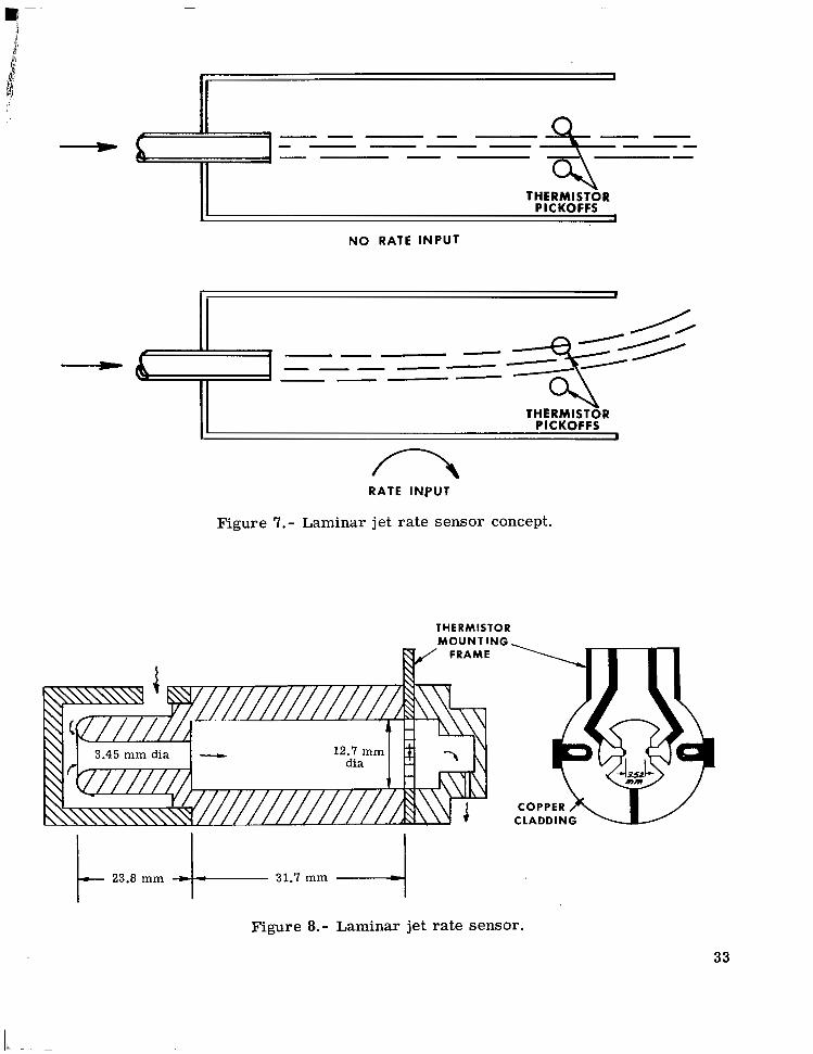
A laminar jet rate sensor was chosen for this application because of its simple con- struction and good performance (ref. 3) . The principle of operation is shown in figure 7. A laminar jet of air is directed across an enclosed chamber and between a pair of self- heated thermistors. When the device is subject to an angular rotation about an axis per- pendicular to the plane of the illustration, the inertial properties of the jet cause it to be deflected as shown. The magnitude and sense of the deflection are proportional to the magnitude and sense of the rate input. Differential cooling of the thermistors by the jet provides an electrical output signal.
Figure 8 shows the basic dimensions of the sensor used in the flight tests. Three plastic castings make up the main body and the supply and exhaust caps. The thermistors a r e attached with soft solder to a mounting frame machined from 1.59 mm (1/16 in.) copper-clad phenolic, printed-circuit board. The copper cladding is etched to bring the thermistor connections out to external tabs which mate with an appropriate connector. Slotted holes allow the position of the frame to be adjusted to center the thermistor pair with respect to the laminar jet. Commercially available matched pairs of glass-coated thermistors are used. They have a resistance of 2000 ohms at 25O C and a diameter of approximately 0.35 mm (0.014 in.) and are operated at a temperature of approximately 105' C.
Flow rates in the instrument are so low as to be very difficult to measure. Mini- mum flow is that which just extends the active jet out to the thermistors. Maximum flow is that at which the jet flow becomes turbulent. In practice, the flow rate is gradually increased until the instrument just becomes sensitive to angular rate. The flow rate is then increased until the output signal just becomes noisy. The flow rate is then reduced to approximately halfway between these two values (about 4.72 X 10⁻⁶ m3/s (0.01 ft3/min) for the test instrument). Within the usable flow range, sensitivity is roughly proportional to flow rate. Since system gain is not very critical in the wing-leveler application, no attempt has been made to regulate flow precisely. A length of capillary tubing is con- nected between the exhaust port of the rate sensor and the aircraft's vacuum supply to res t r ic t the flow to the selected value.
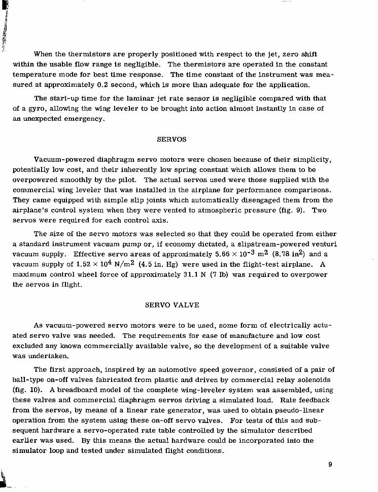
I' When the thermistors are properly positioned with respect to the jet, zero shift within the usable flow range is negligible. The thermistors are operated in the constant temperature mode for best time response. The time constant of the instrument was mea- sured at approximately 0.2 second, which is more than adequate for the application.
The start-up time for the laminar jet rate sensor is negligible compared with that of a gyro, allowing the wing leveler to be brought into action almost instantly in case of an unexpected emergency.
SERVOS
Vacuum-powered diaphragm servo motors were chosen because of their simplicity, potentially low cost, and their inherently low spring constant which allows them to be overpowered smoothly by the pilot. The actual servos used were those supplied with the commercial wing leveler that was installed in the airplane for performance comparisons. They came equipped with simple slip joints which automatically disengaged them from the airplane's control system when they were vented to atmospheric pressure (fig. 9). Two servos were required for each control axis.
The size of the servo motors w a s selected so that they could be operated from either a standard instrument vacuum pump or, i f economy dictated, a slipstream-powered venturi vacuum supply. Effective servo areas of approximately 5.66 X m2 (8.78 in2) and a vacuum supply of 1.52 X lo4 N/m2 (4.5 in. Hg) were used in the flight-test airplane. A maximum control wheel force of approximately 31.1 N (7 lb) was required to overpower the servos in flight.
SERVO VALVE
As vacuum-powered servo motors were to be used, some form of electrically actu- ated servo valve was needed. The requirements for ease of manufacture and low cost excluded any known commercially available valve, so the development of a suitable valve was undertaken.
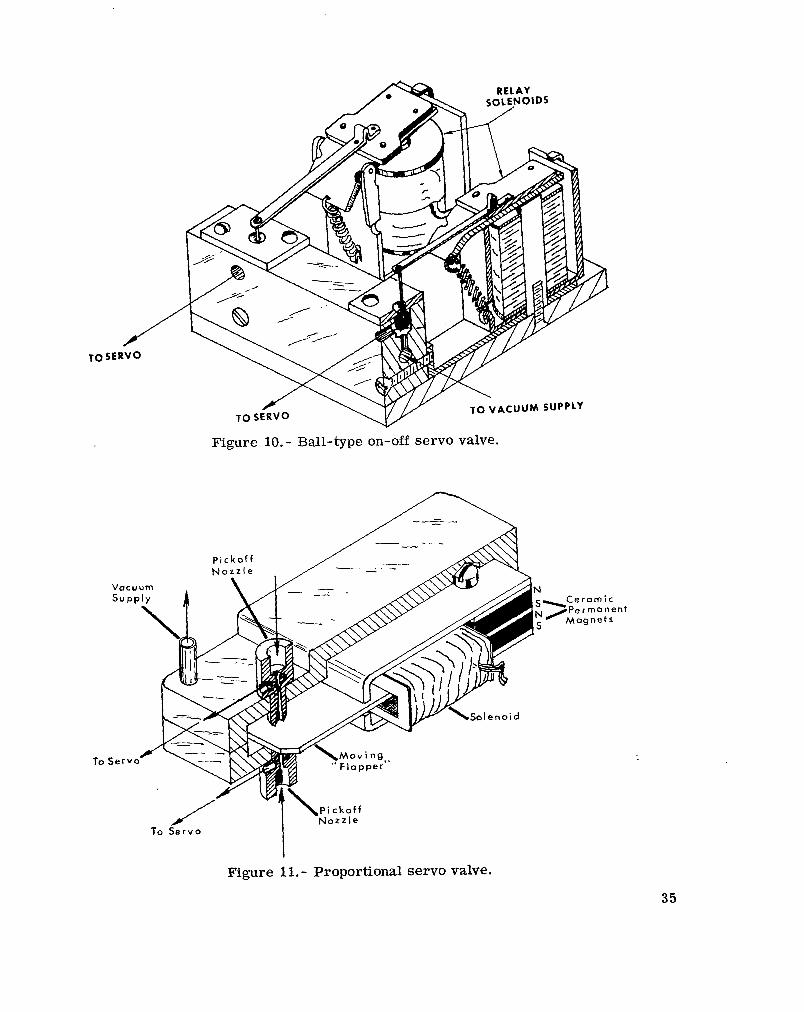
The first approach, inspired by an automotive speed governor, consisted of a pair of ball-type on-off valves fabricated from plastic and driven by commercial relay solenoids (fig. 10). A breadboard model of the complete wing-leveler system was assembled, using these valves and commercial diaphragm servos driving a simulated load. Rate feedback from the servos, by means of a linear rate generator, was used to obtain pseudo-linear operation from the system using these on-off servo valves. For tests of this and sub- sequent hardware a servo-operated rate table controlled by the simulator described earlier was used. By this means the actual hardware could be incorporated into the simulator loop and tested under simulated flight conditions.
9
Stable operation of the system was obtained, but performance was erratic. Also the rapid and continuous operation of the mechanically complex valves did not inspire confidence in their reliability or long life. One operating feature, however, was very attractive. When electrical power was cut off, both servo diaphragms were vented to atmosphere, thus automatically disengaging the servos from the airplane control system without the use of extra valves or clutches.
Several designs for proportional servo valves were tried, culminating in that shown in figure 11. The pneumatic portion of this valve consisted of an improved version of the "flapper valve," or "back-pressure valve." This version not only produced a much more linear variation in output pressure with flapper position than the conventional flapper valve; but, because of the ejector action of the jet and venturi, an output vacuum swing of up to twice the magnitude of the supply vacuum was possible. This feature was most attractive because of the limited vacuum supply available for use with the system.
Although magnetic and mechanical hysteresis proved troublesome, fair performance was obtained from this valve on the flight simulator, and it is believed that with further development a component superior to that used in the flight tests may have resulted.
Meanwhile the development of on-off valves had continued, and the design shown in figure 12 had yielded such satisfactory performance that it was chosen for the flight-test equipment. In this valve, a simplified version of the improved flapper valve was adapted to on-off operation, with the only moving parts being the two flexible steel reeds. These reeds were equipped with soft silicon rubber pads which absorbed the impact at each end of the stroke and served as seals for the valve nozzles. Commercial relay coils were used to drive the reeds. The design retained the advantage of automatically venting both servo motors to atmosphere and allowing them to disengage themselves from the air- plane's control system when the electrical power is cut off.
The valve was operated in the pulse-width-modulated mode at about 18 hertz. The magnitude of the differential vacuum produced, when smoothed by the capacity of the diaphragm servo motors, was proportional to the duty cycle of the pulse-width-modulated signal driving the valve. Since the deflection of the airplane's ailerons is opposed by aerodynamic hinge moments roughly proportional to aileron deflection, an aileron deflec- tion proportional to the rate signal can be obtained without any auxiliary feedback from the control surfaces. The volume of the servo motors in conjunction with the flow resistance of the servo valve furnished the necessary time constant for stable operation of the wing leveler.
Time was not available for any extensive study of the failure modes of the final design, but one valve was operated under normal vacuum load and modulation frequency for 40 hours with no sign of deterioration.
10

1 t 1 One problem in material compatibility was encountered. Aluminum-alloy flapper- valve nozzles were used in the developmental model. These tended to adhere to the silicon rubber pads on the flapper reeds when the valve was not operated for several days,
,i and this fault w a s responsible for the single case of hardware failure which occurred dur- ing the entire flight-test series. The fault was eliminated when the nozzles were made an integral part of the epoxy casting which made up the cover of the valve enclosure and no further trouble was encountered.
1 :
SIGNAL PROCESSING CIRCmTS
The signal processing circuits for the wing leveler are shown in figure 13. The relatively high thermal mass of the smallest available thermistors suitable for the laminar je t ra tesensor pickoffs dictated a constant temperature mode of operation for adequate frequency response. The circuit shown in reference 3 was chosen in the interests of simplicity. An output of about 0.025 V-s-deg'l was obtained from this circuit.
This rate signal was raised to a usable magnitude by an integrated circuit opera- tional amplifier and converted to a pulse-width-modulated signal by a second operational amplifier with a suitable phase-shift network in the feedback loop (ref. 4). A phase- inverting power stage was used to drive the valve solenoids.
Rate-of-turn command signals from the pilot's turn command switch and, later, from the heading-hold system were added to the rate signals at the input of the first oper- ational amplifier. The negative feedback resistance of this amplifier could be varied by means of a step attenuator G2 on the instrument panel so that the overall system gain could be adjusted during flight for optimum performance.
The wing leveler alone consumed about 2 watts of electrical power.
MAGNETIC HEADING HOLD
The first ser ies of flight tests of the wing leveler indicated that the utility of the device could be materially expanded and its dependence upon the zero stability of the rate sensor reduced by the introduction of some form of heading reference that would supply an input to the wing leveler in the form of a yaw rate command. The Earth's magnetic field was chosen for the experiments since it offered an absolute heading reference, inde- pendent of other instrumentation, and might prove more generally useful and easier to test than other possible references.
Some experiments were made with a mechanical compass needle with a photoelectric pickoff and a feedback winding to improve its frequency response. The performance of this device was poor, and as the mechanical complexity of its construction did not promise
11

economical manufacture, other types of magnetic field sensors were investigated. Sev- e ra l configurations of both Hall-effect and fluxgate magnetometers were fabricated and tested. Best performance and simplest construction were realized in the fluxgate device shown in figure 14 (ref. 5).
The ac power for the fluxgate unit was supplied by a simple inverter operating at approximately 675 hertz and producing a square wave input to the excitation winding of the magnetometer of about 0.5 volt peak-to-peak. The demodulator circuit used was chosen for its simplicity and relative insensitivity to small variations in carrier fre- quency (ref. 6). A dc output of approximately 0.32 volts per gauss was obtained. This signal was raised to a level suitable for a command signal to the wing leveler by a single operational amplifier.
Conventionally, when magnetometers are used as heading references in aircraft, they a r e mounted in some remote part of the aircraft as far away from such magnetic anomalies as the engine and the electrical system as possible. Although this is a laud- able procedure, it requires at least two magnetometer elements at the remote location and some type of signal resolver on the pilot's control panel to allow course changes to be made. In the interests of simplicity, it was decided to use a single magnetometer element within reach of the pilot, so that he could make course changes simply by rotating the magnetometer with respect to the aircraft. The deviation errors resulting from this placement would be no worse than those experienced with the conventional wet compass, and cost and complexity would be greatly reduced. A single magnetometer element ,was, therefore; mounted in a large plastic knob, pivoted on a vertical axis and restrained'by a light friction clutch. The assembly included a fixed index pointer and a dial, rotating with the knob, calibrated with the points of the compass. It was mounted at the top of the instrument panel in the test aircraft where it could be easily set by the pilot.
The Earth's magnetic field lies parallel to the Earth's surface only at the magnetic equator, corresponding roughly to the geographic equator, and becomes vertical at the two magnetic poles. Within the United States the direction of this field varies from about 60° to 7 5 O from the horizontal. If a magnetic sensing element is used in the "strap-down'' mode (mounted directly to the airframe), its angular relation to the vertical component of the Earth's field will change when the airplane executes a banked turn; and under certain conditions intolerable errors in the output of the sensor will occur. This effect for the conventional magnetic compass is called "northerly turning error" (ref. 5), and can, at worst, result in an indicated turn in the opposite direction to that actually being made.
The effect of the vertical f l u x component on the wing-leveler-magnetometer com- bination proposed, under the conditions prevailing within the United States, is to cause unstable flight when a northerly course is called for. If a banked turn toward a northerly course is initiated through the magnetic heading-hold device, the influence of the vertical
12
field on the magnetometer will produce a signal calling for a constantly increasing bank
1 : angle in the same direction. The result will be either a large magnitude oscillation in the
heading of the airplane about the northerly course or a continuous turn in the direction of the initial change of heading.
In conventional autopilot designs in which a magnetometer heading reference has been used, the difficulty has been avoided either by stabilizing the magnetometer element with a free gyro so that it remains in a horizontal plane despite any banking of the air- craf t , or by combining the magnetometer with a free directional gyro. For the combina- tion the free gyro is used as the heading reference of the autopilot, and the output of the magnetometer is used to monitor the drift of the gyro so that it may be corrected, either manually or automatically, during level flight. Neither of these approaches are com- patible with the low-cost, high-reliability philosophy of this project, so other possible approaches were sought.
It was reasoned that i f the error in the magnetometer output due to bank angle of the aircraft could be computed in some simple manner, it could be subtracted from the gross magnetometer output to give the correct signal, a function of heading e r r o r only. The output of the magnetometer is proportional to the sine of the angle between the lines of magnetic f l u x and a plane perpendicular to the longitudinal axis of the magnetometer. When the airplane is level, the vertical component of the Earth's magnetic field is per- pendicular to the longitudinal axis of the magnetometer and produces no output. When the magnetometer is se t to hold a west or east heading, its longitudinal axis is parallel to the airplane's roll axis, and the angular, relation between the vertical field component and the magnetometer's axis does not change with bank angle and no output error results. When the magnetometer is set to hold a north o r a south heading, however, its longitudinal axis is perpendicular to the roll axis of the airplane and the vertical component of the Earth's field produces an output proportional to the sine of the bank angle. In fact, the e r r o r introduced by the vertical field component is proportional to both the sine of the bank angle and the cosine of the heading setting of the magnetometer:
R = K sin @ cos H
where
R roll-induced e r r o r
@ bank angle
H heading setting of the magnetometer (zero at N)
K magnitude of the vertical component of the Earth's magnetic field
13

"
In the device flight tested, a scotch yoke mechanism driving a linear potentiometer was attached to the heading-set knob to generate the cos H function. The s in @ func- tion was not directly available from the existing system, but was approximated with suf- ficient accuracy by the rate-of-turn signal from the rate sensor. Figure 15 shows the basic cir.cuit used to obtain the desired product. In practice, the gain of the circuit Kc was adjusted to exactly cancel the local vertical field component for the bank angle and rate-of-turn signal corresponding to a standard turn at standard cruising speed. Normal variations in turning rate and aircraft speed resulted in small errors in the overall sys- tem gain that were generally not discernible in terms of system performance. The mag- netometer assembly used in the flight tests is shown in figure 16.
A mechanically simpler version of this compensation scheme, developed after the flight tests had been completed, is shown in figure 17. Here, a magnetic field, approxi- mately equal to and opposite in sign to the component of the vertical field acting along the pitch axis of the airplane, is generated by a solenoid coil surrounding the magnetometer element. Rotation of the magnetometer element within this solenoid automatically pro- duces the cos H function without the use of the scotch yoke mechanism and potentiometer used in the flight model.
No attempt was made to compensate for deviation e r r o r due to the close proximity of the magnetometer to the aircraft's engine and electrical system. This error was esti- mated, from the flight-test data, to reach a maximum of about 30°. This error would, in a service instrument, be minimized by a system of permanent magnets or solenoids sim- ilar to that used for compensating conventional compasses.
A block diagram of the combined wing leveler and heading-hold system is shown in figure 18. Total electrical power required for both wing leveler and heading-hold system was 4.75 watts.
ENVIRONMENTAL TESTS
Since the flight-test components were custom made and generally not of a design directly suitable for production, only enough environmental testing was done to assure that no catastrophic failures would occur during the flight tests and that no fundamental failure modes were inherent in the component designs. Of special concern was the effect of a severe vibration environment on the operation of the servo valve and on the laminar air jet in the rate sensor.
The vibration power spectrum used was based upon data supplied by the manufac- turer of the test aircraft (fig. 19). A mixed sin/random vibration test was conducted at the levels shown. A linear sinusoidal sweep from 70 to 90 hertz was used, with a sweep speed of 4 oct/min to better simulate the high-density acceleration present in that bandwidth.
14

/[I 1 Erratic operation of the rate sensor occurred under these conditions and was traced
to the high level of acoustic energy inside the instrument case due to vibration of the flat sheet-metal areas of the case. This acoustic energy was being fed into the laminar jet nozzle of the rate sensor through the air inlet port, which was initially open to the inside of the instrument case. Connecting this inlet port to the exterior of the case with a short length of plastic tubing overcame this difficulty. After a failure in the magnetometer inverter transformer due to improper potting was corrected, the equipment was subject to the test vibration for a total of 6 hours without further difficulty.
A rough check of the equipment's susceptibility to ignition noise was made by oper- ating the complete system in close proximity to, and from the same power supply as, a small vibrator induction coil. No adverse effects were noted.
FLIGHT-TEST PROGRAM
Test Airplane
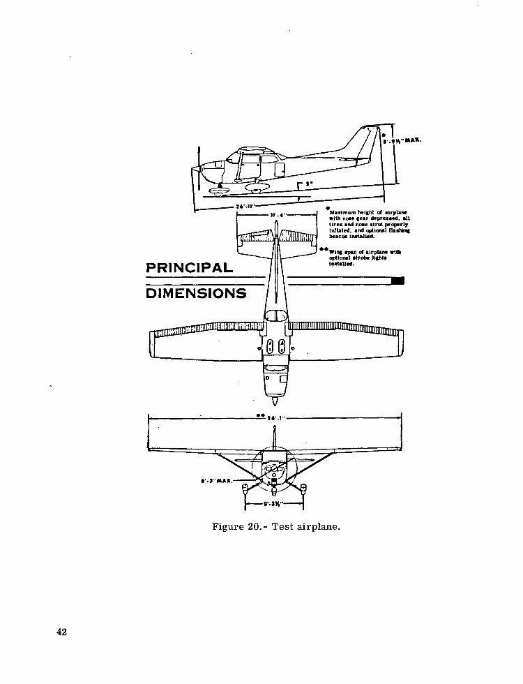
The airplane used in the flight-test program was a NASA-leased Cessna 172 Skyhawk (fig. 20).
A commercial vacuum-operated wing-leveler system using a rate gyro as a sensing element was installed in the test airplane to serve as the basis for comparisons. This system used both aileron and rudder servos connected in parallel. An array of selector valves was installed in the test airplane to allow the servos to be connected to either the commercial wing leveler or the gyro-less wing leveler under test, and to allow either wing leveler to be operated with both aileron and rudder servos or with aileron servos alone.
Instrumentation
A digital data acquisition system was installed in the test airplane for the flight- test program to record the parameters shown in table 11. All data were recorded on mag- netic tape onboard the airplane. The data tapes were played back on an oscillograph recorder, and selected tests were traced to produce the curves shown in this paper.
In order to facilitate flight-test procedures, step attenuators were installed in the wing-leveler-heading-hold panel designed for the flight tests, so that important system gains could be adjusted in flight (fig. 2 1). Figure 2 1 explains the functions of the panel including the calibrations of these attenuators. A calibrated lever, also in the panel, per- mitted adjustment of the tilt angle of the rate sensor b t in flight. The gains of the atten- uators and the tilt angle would normally be preset and not appear on the panel. Service controls would include only the turn command switch, the t r im knob, the power switch, the heading-hold engage switch, and the heading-set dial on the magnetometer assembly.
15
I- -

Procedures
The wing-leveler system gain G2 and rate-sensor tilt angle 6t were experimen- tally optimized for both cruise and climb modes of flight. Data could not be obtained in the power-off approach mode, since the vacuum pump on the airplane could not supply sufficient vacuum to operate the system in this mode. Optimization criteria were based upon the system's response to a transient input. Since the initial conditions used in the simulation studies (50° bank angle and zero turn rate) were, of course, not practical for the flight tests, the airplane, with wing leveler in operation, was put into a coordinated turn of approximately 50° bank angle by overpowering the wing-leveler servos. The con- trol wheel was then released and the transient response of the airplane-wing-leveler com- bination recorded. Response of the commercial wing leveler to the same initial condi- tions was recorded for comparison. AI1 tests were made at pressure altitudes of 731.5 to 1066.8 m (2400 to 3500 ft). Cruise tests were made at indicated airspeeds of 52.7 to 61.7 m/s (118 to 138 mph), and climb tests at 40.2 to 44.7 m/s (90 to 100 mph).
As stable operation was obtained from both wing levelers using aileron servos alone, most of the tests were made in this configuration. For comparison, some data was taken with each system using both aileron and rudder servos.
Some east-west flights were made with the magnetic heading-hold system before the northerly turning error correction device was installed, to determine approximate gain settings. After the correction device was added, the two attenuators related to the heading-hold feature (saturation and GI) were adjusted so that when a course change large enough to saturate the magnetometer output was commanded by rotation of the heading-set knob the airplane would assume a standard 2-minute turn (3 deg/sec turn rate) and roll out on the new heading with a damping factor of approximately unity.
A short north-south cross-country flight was made to verify the heading-hold per- formance. Since the only instrumentation available in the aircraft for recording heading was a free gyro with poor drift characteristics, a small magnetic compass was visually observed during this cross-country flight to determine course-holding ability.
Results
The flight-test results are presented in figures 22 to 28. Although evaluation of the transient response of the wing leveler was based primarily on the plots of roll angle, plots of yaw rate, aileron deflection, and rudder deflection, when pertinent, have been included.
Best transient response of the wing leveler in the cruise mode was obtained at a rate-sensor tilt angle 6t of 15' and a system gain setting G2 of 4, as shown in fig- ure 22. These settings resulted in a poorly damped response in the climb mode, however, so optimization in this mode was undertaken, resulting in the performance shown i n fig- ure 23, at a tilt angle of 30° and a system gain setting of 4. These parameters resulted
16

f
in rather sluggish response in the cruise mode so the compromise tilt angle of 22.5O was finally adopted, giving satisfactory performance in both cruise and climb modes (fig. 24). At this tilt angle a high system gain (G2 = 0.5) could be used in the cruise mode (fig. 25) with a slight improvement in transient response, but this gain setting resulted in rather severe oscillations in the climb mode. The rate-sensor tilt angle of 22.5O with the sys- tem gain setting of 4 was selected as the best compromise for this particular installation.
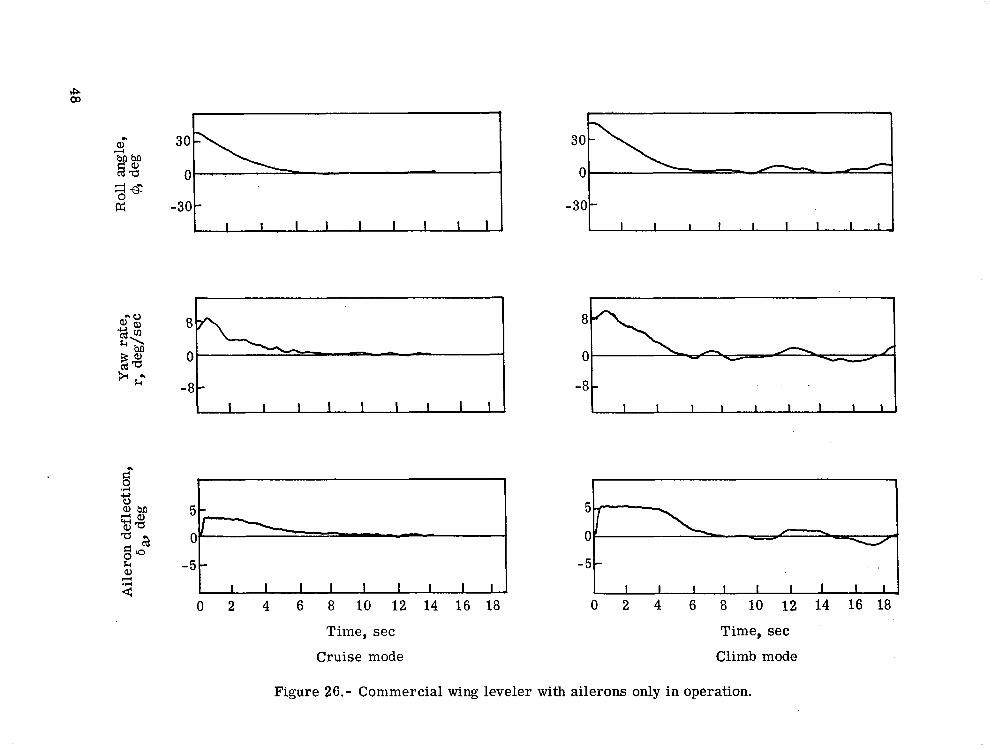
Performance of the commercial wing leveler with ailerons only in operation is shown in figure 26 and is seen to be virtually identical with that of the optimized gyro- less wing leveler.
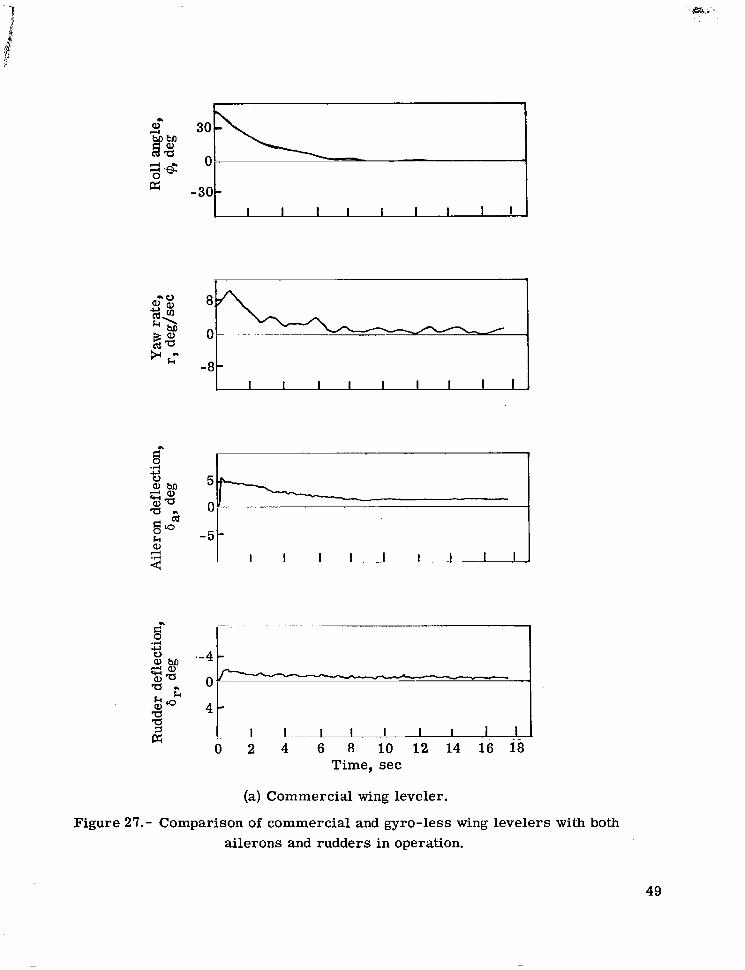
Figure 27 shows the performance of both the gyro-less wing leveler and the com- mercial wing leveler with the rudder, in addition to the ailerons, in operation. The fig- ure is comparable to figures 24 and 26. The only significant difference in the perfor- mance with and without the rudder servos appears to be at the very beginning of the roll attitude plot. Without the rudder servos there is a noticeably greater lag in building up a corrective roll rate. This effect is probably due to adverse aileron yawing moment, and may be more serious in other airplane configurations. In the test airplane the dif- ference was not noticeable to the pilot. It can be seen from figure 27 that the rudder deflections were very small. This was due to the heavy rudder-centering springs in the test airplane, installed evidently for the purpose of keeping the nose wheel centered.
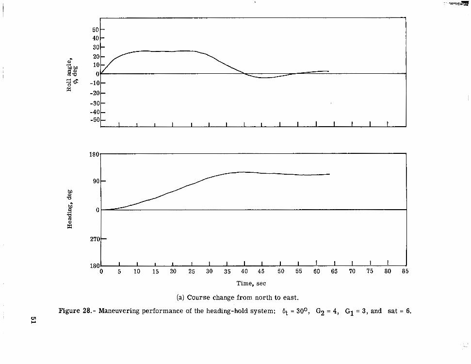
Maneuvering performance of the heading-hold system is shown in figure 28. The tests were made by quickly rotating the magnetometer head 90° for each run and record- ing the heading change of the airplane by means of a directional gyro. The evident dis- parity between the changes in magnetometer head settings and the changes in course is due to the uncompensated deviation error in the magnetometer. A course change from north to east is shown in figure 28(a) where the northerly turning error does not affect the system. A small overshoot is indicated. Figure 28(b) shows a course change from west to north, which, with no compensation, should produce the maximum destabilizing effect due to northerly turning error. A somewhat larger overshoot is indicated, but the system is completely stable. Figure 28(c) shows a course change from east to south, which should have produced a highly overdamped transient due to northerly turning error. No overshoot is indicated, but neither is excessive overdamping evident. Since the compen- sation system gain (Kc in fig. 15) had been adjusted in the laboratory before the equip- ment had been installed in the airplane, and the flight schedule did not permit optimization under actual flight conditions, the compensation achieved was considered very good. The differences in response observed in the records were not noticeable to the pilot.
The cross-country flight tests of the wing-leveler-heading-hold combination con- sisted of one flight of approximately 20 minutes on a south course at an altitude of 1372 m (4500 ft) i n smooth air and a return flight of about the same duration on a north course at
17

an altitude of 305 m (1000 ft) in very rough air. Under the smooth air conditions, short- term deviations of heading of about *2O were observed from the directional gyro, but no long-term drift from the south course could be detected from visual observation of the magnetic compass. Under the very rough air conditions, short-term deviations of as much as *15O were noted, but, again, no long-term drift could be detected using the mag- netic compass as a reference, although the airplane's directional gyro reference drifted about 15O during this flight.
CONCLUSIONS
A satisfactory wing-leveler type of stability augmentation system has been devel- oped in which design emphasis was placed upon simplicity, low cost, and reliability. The utility of the wing leveler was extended by the addition of a strap-down magnetometer heading-reference device. Several major components, including a fluidic inertial rate sensor to replace the gyro of previous systems, an electropneumatic servo valve, and the strap-down magnetic heading-reference device were developed especially for this appli- cation. Flight tests in a typical, single-engine light airplane indicated wing-leveler per- formance equal to that of a contemporary commercial wing leveler. The drift-free heading-hold capability was also demonstrated.
Langley Research Center, National Aeronautics and Space Administration,
Hampton, Va., February 22, 1974.
18

REFERENCES
1. Driscoll, Norman R.: Effects of a Simple Stability Augmentation System on the Per- formance of Non-Instrument-Qualified Light-Aircraft Pilots During Instrument Flight. NASA T N D-3970, 1967.
2. Phillips, William H.; Kuehnel, Helmut A.; and Whitten, James B.: Flight Investigation' of the Effectiveness of an Automatic Aileron Trim Control Device for Personal Airplanes. NACA Rep. 1304, 1957. (Supersedes NACA TN 3637.)
3. Moore, Alvin G.: Angular Movement Sensing Device. U.S. Pat. 3,500,691, Mar. 17, 1970.
4. Loe, James M.: Duty Cycle Modulators are Simple and Versatile. Elec. Design News, Apr. 15, 1971, pp. 47-49.
5. Anon.: Encyclopaedia Britannica. Vol. 6. Encyclopaedia Britannica, Inc., c.1973, pp. 231-233.
6. Atkinson, P. D.; and Hemingway, A. V.: An Even-Harmonic Magnetic Amplifier. Electron. Eng., vol. 26, no. 321, Nov. 1954, pp. 482-485.
19

TABLE I
FLIGHT CONDITIONS AND AIRCRAFT DYNAMICS DATA USED IN SIMULATION
Aircraft . . . . . . . . . . . . . . . . . . . . . . . . . . . . . . . . . . . . . Cessna 310
Altitude . . . . . . . . . . . . . . . . . . . . . . . . . . . . . . . . . . 2438 m (8000 ft)
Speed . . . . . . . . . . . . . . . . . . . . . . . . . . . . . . . . 95.4 m/s (213.4 mph)
Roll-moment parameters: . . . . . . . . . . . . . . . . . . . . . . . . . . . . . . . . . . . . . . . . . . . . . . . Lb . . . . . . . . . . . . . . . . . . . . . . . . . . . . . . . . . . . . . . . . . -23.4
Lb a . . . . . . . . . . . . . . . . . . . . . . . . . . . . . . . . . . . . . . . . . -36.8
Lb . . . . . . . . . . . . . . . . . . . . . . . . . . . . . . . . . . . . . . . . . -6.72
Li . . . . . . . . . . . . . . . . . . . . . . . . . . . . . . . . . . . . . . . . . 0.89
Yaw-moment parameters: Nb , . . . . . . . . . . . . . . . . . . . . . . . . . . . . . . . . . . . . . . . . . -14.2
' I
Ni . . . . . . . . . . . . . . . . . . . . . . . . . . . . . . . . . . . . . . . . . . '17.84
NA a . . . . . . . . . . . . . . . . . . . . . . . . . . . . . . . . . . . . . . . . . 2.15
N i . . . . . . . . . . . . . . . . . . . . . . . . . . . . . . . . . . . . . . . . . -0.18
N i . . . . . . . . . . . . . . . . . . . . . . . . . . . . . . . . . . . . . . . . . -1.06
Side-force parameters: I Y6, . . . . . . . . . . . . . . . . . . . . . . . . . . . . . . . . . . . . . . . . . 25.98
Yp . . . . . . . . . . . . . . . . . . . . . . . . . . . . . . . . . . . . . . . . . -0.24
20
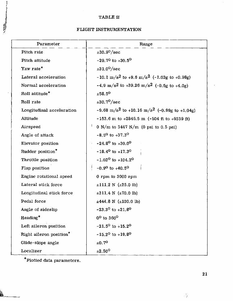
TABLE 11
FLIGHT INSTRUMENTATION
Parameter
Pitch rate
Pitch attitude
Yaw rate*
Lateral acceleration
Normal acceleration
Roll attitude*
Roll rate
Longitudinal acceleration
Altitude
Airspeed
Angle of attack
Elevator position
Rudder position*
Throttle position
Flap position
Engine rotational speed
Lateral stick force
Longitudinal stick force
Pedal force
Angle of sideslip
Heading*
Left aileron position
Right aileron position*
Glide-slope angle
Localizer * Plotted data parameters.
Range
k30. g0/sec
-29.70 to +30.5'
53 l.OO/sec
- 10.1 m/s2 to +9.6 m/s2 (-1.03g to +0.98g)
-4.9 m/s2 to +39.26 m/s2 (-0.5g to +4.0g)
k58.5O
k30.7°/sec
-9.68 m/s2 to +10.16 m/s2 (-0.99g to +1.04g)
-153.6 m to +2846.5 m (-504 f t to +9339 ft)
0 N/m to 3447 N/m (0 psi to 0.5 psi)
-8.5' to +37.3'
-24.8' to +30.0°
-18.4' to +17.3' ~
-1.02' to +104.2'
-0.9O to +40.5' I
0 rpm to 3000 rpm
~ 1 1 1 . 2 N (~25 .0 lb)
k311.4 N ( ~ 7 0 . 0 lb)
*444.8 N (k100.0 lb)
-23.3' to +21.8'
Oo to 360'
-21.5' to +15.2'
-15.2' to +19.8'
r tO.7O
*2. 50°
21

Figure 1.- Curtis flying boat demonstrating the original Sperry "Aeroplane Stabiliser" in 1914.
22

Figure 2.- Diagram for the simulation of the aircraft lateral dynamics.
23

ba n r
30 t 0
-101-
-5 "1 - I I I I I I I I 1 I O 2 4 6 8 10 12 14 16 18
Time, sec
Figure 3. - Block diagram and data for the simulation of the unaugmented airplane.
24

I I I I
-10 I -
.?I E? CI 5 -
5% =;;l $0
2
0 ah0
0
-5 - r
k a 4 I I I I I I I I I
0 2 4 6 8 10 12 14 16 18
Time, sec
Figure 4.- Block diagram and data for the simulation of the wing leveler with constant rate actuation of the ailerons (ref. 2): switching threshold for o = 0.1 deg/sec and aileron actuation speed = kl .0 deg/sec. tit = 14O.
25

-30 I I I I I L - ~ 1 I I
-10%
Time, sec
(a) Aileron deflection proportional to the integral of the rate signal: dt = 19O and system gain = 0.5.
Figure 5.- Block diagrams and data for simulations of alternate concepts for deflecting the controls for a wing leveler with a single tilted-axis rate sensor.
26

cos 6 t 1
I I I I I I I I I I I
-10 I I I I I I I I I
-5 O L 0 2 4 6 8 10 12 14 16 18
Time, sec
(b) Aileron deflection proportional to the rate signal: Gt = 22O and system gain = 0.5.
Figure 5.- Continued.
27

I 1
I I I 1 I I I I I I
c) 2 4 6 8 10 12 14 16 18 Time, sec
(c) Both aileron and rudder deflections proportional to the rate signal: 6, = 8 . 5 O and system gains = 5 for both aileron and rudder, producing identical data on lower plot.
Figure 5.- Continued.

ba r
I I
:@ P; -30 I
c- -d 0
0 5I -51 0 2 4 6 8 10 12 14 16 18
Time, sec
(d) Rudder deflection proportional to the rate signal: Gt = 8.5O and system gain = 5.
Figure 5. - Concluded.
29

I I I I I I I I I I J
-5 l?zzzd 0 2 4 6 8 10 12 14 16 18
Time, sec
(a) 7 = 4 sec.
Figure 6.- Effect of time lag T when aileron deflection is proportional to the rate signal: 6t = 22O and system gain = 5.
30

-30 I I I I I I I I I
'"4 0 -10 -
I I I I I I I I I
5i 0
0 2 4 6 8 10 12 14 16 18
Time, sec
(b) 7 = 10 sec.
Figure 6. - Continued.
31

0 d .d
5 - -
0- -
-5- I I I 1 I I I I I
Time, sec 0 2 4 6 8 10 12 14 16 18
(c) 7 = 20 sec.
Figure 6. - Concluded.
32
~~~ - - " . i
__t ""- " - - - *- 7
T H E R M I S T O R PICKOFFS
NO R A T E I N P U T
"
T H E R M I S T O R PICKOFFS
i
n R A T E I N P U T
Figure 7.- Laminar jet rate sensor concept.
THERMISTOR MOUNTING.
1 23.8 mm -1 31.7 mm 4 Figure 8.- Laminar jet rate sensor.
33

t
i A i l e r o n C o n t r o l C a b l e
/ D i u p h r a g m
Figure 9.- Diaphragm servo motor: two required for each control axis.
34
I Figure 11.- Proportional servo VdVe.
35

I I1
SOLENO
T O VACUUM
Figure 12.- Reed-type on-off servo valve.
36

, I/. BPIDGE
IEADING
NGAG E HOLD
VALVE SOLENOIDS
P WM CONVERTER
- I - - 1 PHASE SHIFT
NETWORK
RATE BRIDGE
HEADING HOLD
OUTPUT INPUT
POWER I AMPLIFIER
Figure 13.- Wing-leveler circuit.

.. , ". .. .
76.2 MM X 5.92 MM x l O O t OOOT MM M U METAL STRIPS
DEMODULATOR
Figure 14.- Magnetometer and demodulator circuit.
RATE BRIDGE
? INPUT P SCOTCH YOKE COSINE MECHANISM
ON HEADING I I d SET KN B e- 11 G1
HEADING HOLD
OUTPUT V
MAGNETOMETER DEMODULATOR 0 -
INPUT 0
Figure 15.- Northerly turning error compensation circuit used in the flight tests.
38

,-4739
Figure 16.- Magnetometer assembly.
39

PITCH
OMPENSATION
BRIDGE RAT
INPU
Figure 17.- Revised northerly turning error compensation circuit.
SERVO
PULSE WIDTH MODULATOR
HEADING .
SERVO
MAGNETOMETER
Figure 18.- Block diagram of the wing leveler and heading-hold system used in the flight tests.
40

10 50 100 500 1000 3000
f requency (Hz) Figure 19.- Vibration test envelope.
41
PRINCIPAL
DIMENSION§
l A l 1 . d .
Figure 20.- Test airplane.
42

L- 73- 5468
Functions and calibrations
Turn rate Attenuator for setting the turn rate to be introduced by the Turn knob. Numbers on the dial correspond roughly to the turn rate in deg/sec
Sat.
G1
G2
Tilt
Attenuator for setting the maximum turn rate command introduced into the wing leveler by the magnetic heading reference. Numbers corre- spond to turn rate in deg/sec
Attenuator for setting the gain of the magnetometer preamp. The low- est numbers indicate the highest gain. Settings of 1, 2, 3, 4, and 5 cor- respond to 5O, 15O, 25O, 30°, and 45' of course heading error , respec- tively, required to saturate the magnetometer preamp
Attenuator for setting the gain of the wing leveler. Numbers correspond roughly to the turn rate in deg/sec required to saturate the servo valve
Lever for setting the angle of the rate sensor with respect to the air- craft longitudinal axis. At Oo, the sensor is sensitive only to yaw rate
Figure 21.- Wing-leveler-heading-hold flight-test panel.
43

I I 1 I I I I I I I
-301 1 1 I 1 I I I I I I )
.r( B c) 0 5 $ 0 a,- 0 =;;1 5 0
Q M
k a,
- 5 - - 5 -
z I I I I I I I I I 0 2 4 ' 6 8 10 12. 14 16 18 0 2 4 6 a io 12 14 16 18
Time, sec Time, sec Cruise mode Climb mode
Figure 22.- Flight-test data for the gyro-less wing leveler: 6t = 15O and G2 = 4.

1 I I I I I I I I I
. .
-d-
5 I 0 -I
- 5 t 0 2 4 6 8 10 12 14 16 18
Time, sec
Cruise mode
-30 - I I I .. > I I I I (
-8 t
0 5l -5t
I I I I I I I I I 0 2 4 6 8 10 12 14 16 18
Time, sec
Climb mode
Figure 23.- Effect of increased rate-sensor tilt angle on gyro-less wing leveler: 6t = 30' and G2 = 4.

.rl I I
r-l
2 I I I I I 1 1 I I I J 0 2 4 6 8 10 12 14 16 18
Time, sec
I I I I I I I I I I J
I I I I I I I I I I J 0 2 4 6 8 10 12 14 16 18
Time, sec
Cruise mode Climb mode
Figure 24.- Performance of gyro-less wing leveler with compromise tilt angle: 6t = 22.5' and G2 = 4.

-30 - I I I I I I I I I h
-8 - a I I I I I I I I I .
.-5 - I I I I I I I I I
0 2 4 6 8 10 12 14 16 18 Time, sec
30.,1 0
-30 c
8
0
I I I I I I I I I I
5
0
-5 - I I I I I I I I I I
0 2 4 6 8 10 12 14 16 18 Time, sec
Cruise mode Climb mode
Figure 25.- Effect of increased system gain on gyro-less wing leveler: 6t = 22.5' and G2 = 0.5 .
P; -30
-5 : p " - I 1 I I I I I I I I I J 0 2 4 6 8 10 12 14 16 18
3 0 _ i 0 -301
0 5l 1 I I I I I I I I I
0 2 4 6 8 10 12 14 16 18
Time, sec Time, sec
Cruise mode Climb mode
Figure 26.- Commercial wing leveler with ailerons only in operation.
I i
Time, sec
(a) Commercial wing leveler.
Figure 27.- Comparison of commercial and gyro-less wing levelers with both ailerons and rudders in operation.
49

2 8 P; 0
1 I I I I I I I I I I
1 1
8 P " - 4 0 -8-
I I I I I I I I I ,
5 -
0 I
B c.
I
-c, .A U
0 W M - 4- W * a - 0"
0 2 4 6 8 10 1 2 1 4 16 18 Time, sec
(b) Gyro-less wing leveler: 6t = 22.5' and G2 = 4.
Figure 27.- Concluded.
50
50
- 30
- 40
-
2& -10- E -20
-50- - -40
-30-
-
I I I I I I I I I I I I I I I I
180
90
0
27C
180 I 1 I I I I I I I I I I I I I I J 0 5 10 15 20 25 30 35 40 45 50 55 60 65 70 75 80 85
Time, sec
(a) Course change from north to east.
Figure 28.- Maneuvering performance of the heading-hold system: 6t = 30°, G2 = 4, G1 = 3, and ul
sat = 6. r

40 30
- 20 -30 -40 - 50 I 1 I 1 I I I I I I I I I I I I
180
1800 I I I I I I I I I I 1 I I I I I 5 10 15 '20 25 30 35 40 45 50 55 60 65 70 75 80 85
Time, sec
(b) Course change from west to north.
Figure 28. - Continued.

r
40 501 30 -
ai- - 32 Z" L1: -10-
-20
- -40
-30-
-
-50 I I I I I I I I I I I I I I I I
180
90 -
0
270 -
180 I I I I 1 I I I I I I I I I I I 0 5 10 15 20 25 30 35 40 45 50 55 60 65 70 75 80 85
Time, sec
(c) Course change from east to south.
Figure 28. - Concluded,

NATlO INISTRATION
.
POSTMASTIR : If Undeliverable (Section 158 Postal1 Mnnunl) Do Not Return
NASA
“The aeronautical and space activities of the United States shall be conducted so as to contribute . . . t o the expansion of haman knowl- edge of phenomena in the atmosphere apd space. The Administration shall provide for the widest practicable and appropriate dissemination of information concerning its activities and the results thereof.”
“NATIONAL AERONAUTICS AND SPACE ACT OF 1958
SCIENTIFIC AND TECHNICAL PUBLICATIONS TECHNICAL REPORTS: Scientific and ,
technical information considered important, complete, and a lasting contribution to existing knowledge.
TECHNICAL NOTES: Information less broad in scope but nevertheless of importance as a contribution to existing knowledge.
TECHNICAL MEMORANDUMS: Information receiving limited distribution because of preliminary data, security classifica- tion, or other reasons. Also includes conference proceedings with either limited or unlimited distribution.
CONTRACTOR REPORTS: Scientific and technical information generated under a NASA contract or grant and considered an important contribution to existing knowledge.
TECHNICAL TRANSLATIONS: Information published in a foreign language considered to merit NASA distribution in English.
SPECIAL PUBLICATIONS: Information derived from or of value to NASA activities. Publications include final reports of major projects, monographs, data compilations, handbooks, sourcebooks, and special bibliographies.
TECHNOLOGY UTILIZATION PUBLICATIONS: Information on technology used by NASA that may be of particular interest in commercial and other- non-aerospace applications. Publications include Tech Briefs, Technology Utilization Reports and Technology Surveys.
Details on the availability of these publications may be obtained from:
SCIENTIFIC AND TECHNICAL INFORMATION OFFICE
N A T I O N A L A E R O N A U T I C S A N D S P A C E A D M I N I S T R A T I O N Washington, D.C. 20546