Embed Size (px)
Citation preview
I ' N A S A C O N T R A C T O R N A S A C R - 2 4 1 8 R E P O R T
00 7 1 - N
= I
1
U
4 m 4 z
DEVELOPMENT AND FLUERIC SOUNDING
by Vit~cet2t P. Murchese
Prepared by
THE SINGER COMPANY
KEARFOTT DIVISION
Litt le Falls, N.J.
f o r Lntigley Research Cerzter
DEMONSTRATION OF ROCKET MOTOR IGNITION
N A T I O N A L A E R O N A U T I C S A N D SPACE A D M I N I S T R A T I O N W A S H I N G T O N , D. C. JUNE 1974
1. Report No.
NASA CR-2418
DEVELOPMENT AND DEMONSTRATION OF FLUERIC SOUNDING ROCKET MOTOR IGNITION
2. Government Accesion No. 3. Recipient's Catalog No.
4. Title and Subtitle
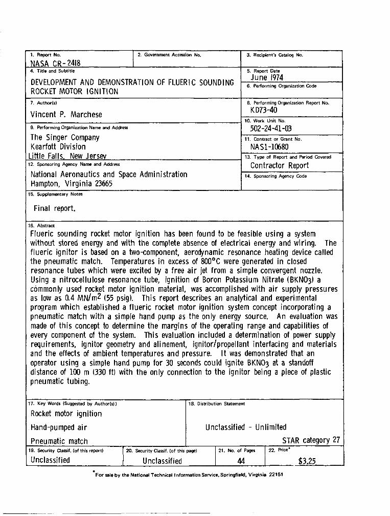
6. Abstract
Flueric sounding rocket motor ignit ion has been found to be feasible us ing a system without stored energy and wi th t h e complete absence of electrical energy and wiring. The f luer ic ignitor i s based on a two-component, aerodynamic resonance heating device called t h e pneumatic match. Temperatures in excess of 8OOOC were generated in closed resonance tubes which were excited by a free a i r jet from a simple convergent nozzle. Using a nitrocel lulose resonance tube, ignit ion of Boron Potassium Nitrate (BKN03) a commonly used rocket motor ignit ion material, was accomplished w i th a i r supply pressures as low as 0.4 MN/m2 (55 psig). This report describes an analytical and experimental program wh ich established a f luer ic rocket motor ignit ion system concept incorporating a pneumatic match w i th a simple hand pump as the only energy source. A n evaluation was made of t h i s concept to determine the margins of the operating range and capabilities of every component of t he system. This evaluation included a determination of power supply requirements, ignitor geometry and alinement, ignitor/propellant interfacing and materials and the effects of ambient temperatures and pressure. It was demonstrated that an operator us ing a simple hand pump for 30 seconds could ignite BKN03 at a standoff distance of 100 m (330 ft) w i th the only connection t o the ignitor being a piece of plastic pneumatic tubing.
5. Rewrt Date
7. Author(s)
Vincent P. Marchese 9. Performing Organization Name and Address
The Singer Company Kea r f ott Di v i si o n -itt ie Falls, New Jersey 2. Sponsoring Agency Name and Address
Hampton, V i rg in ia 23665 National Aeronautics and Space Administration
8. Performing Organization Report No.
K D73 -40
502-24-41-03
NA S1-10680
10. Work Unit No.
11. Contract or Grant No.
13. Type of Report and Period Covered
Contractor Report 14. Sponsoring Agency Code
For sale by the National Technical Information Service, Springfield, Virginia 22151
7. Key Words (Suggested by Author(s))
Rocket motor ign i t ion 18. Distribution Statement
Hand-pumped a i r
Pneumatic match
Unclassified - Unlimited
STAR category 27 '9. Security Classif. (of this report) 20. Security Classif. (of this page)
U nc I a ssi f ied Unclassified 21. NO. of pages 22. Rice'
44 $3.25.
TABLE OF C9NTENTS
1. SUMMARY
2. INTRODUCTION
3. INSTRUMENTATION
4.1 Pneumatic Match 4.2 Energy Source 4.3 Propellant
5. PROCEDURE
5.1 Pneumatic Match 5.2 Energy Source 5.3 Propellant
6. RESULTS AND DISCUSSIONS
6.1 Pneumatic Match 6.2 Energy Source 6.3 Propellant
7. CONCLUSIONS
8. REFERENCES
9. ILLUSTRATIONS AND TABLES
Page No. 1
2
5
6
6 7 8
9
9 11 11
12
12 14 16
17
20
21
iii
DEVELOPMENT AND DEMONSTRATION OF F LUERlC SOUNDING ROCKET MOTOR IGNITION
By Vincent P. Marchese The Singer Company
1. SUMMARY
Flueric sounding rocket motor ignition has been found to be feasible using a system without stored energy and with the complete absence of electrical energy and wiring. The flueric ignitor i s based on a two-component, aerodynamic resonance heating device called the pneumatic match. Temperatures in excess of 800°C were generated in closed resonance tubes which were excited by a free air je t from a simple convergent nozzle. Using a nitrocellulose resonance tube, ignition of Boron Potassium Nitrate (BKN03) a commonly used rocket motor ignition material, was accomplished with air supply press- ures as low as 0.4 MN/m2 (55 psig). This report describes an analytical and experimental program which established a flueric rocket motor ignition system concept incorporating a pneumatic match with a simple hand pump as the only energy source. An evaluation was made of this concept to deter- mine the margins of the operating range and capabilities of every component of the system. This evaluation included a determination of power supply requirements, ignitor geometry and alignment, ignitor/propellant interfacing and materials and the effects of ambient temperatures and pressure. It was demonstrated that an operator using a simple hand pump for 30 seconds could ignite BKN03 a t a standoff distance of 100 m (330 f t ) with the only connection to the ignitor being a piece of plastic pneumatic tubing.
2. INTRODUCTION
The flueric rocket ignition system can be divided into three basic parts: an energy source of com- pressed air, the pneumatic match, and the flame producing propellant toignite the rocket motor. The pneumatic match, the key element of the system, has no moving parts and is powered by the flow of compressed gases.
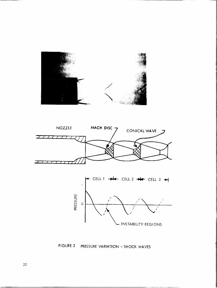
Basically, the pneumatic match consists of two essential parts: a resonance tube (hollow cavity closed a t one end), and a convergent excitation nozzle as shown schematically in Figure 1. The device func- tions when the open end of the cavity is placed in the compression region of a free je t emanating from the nozzle. When the flow emerges from the nozzle, it accelerates to supersonic speed and then readjusts to subsonic speed by compression through a shock wave. The process creates a series of diamond- shaped cells of alternate supersonic and subsonic flow. These cells or conical shock waves (Mach diamonds) intersect the je t axis throughout the length of the je t (Figure 2). A plot of a typical static pressure distribution along the axis of the j e t isalso shown in Figure 2. It can be seen that the pressure rises in the conical fronts of the diamonds and drops in the divergent portions to a minimum at the intersections. It was discovered that by placing a cavity in certain portions of the jet a self-sustaining system of oscillations was created by driving the gas in the cavity into resonance. The portions of the jet structure which have been found to give rise to these oscillations are indicated by dashed lines in Figure 2. They are located between the Mach disk and the end of the cell. The first cell has been found to produce the best results.
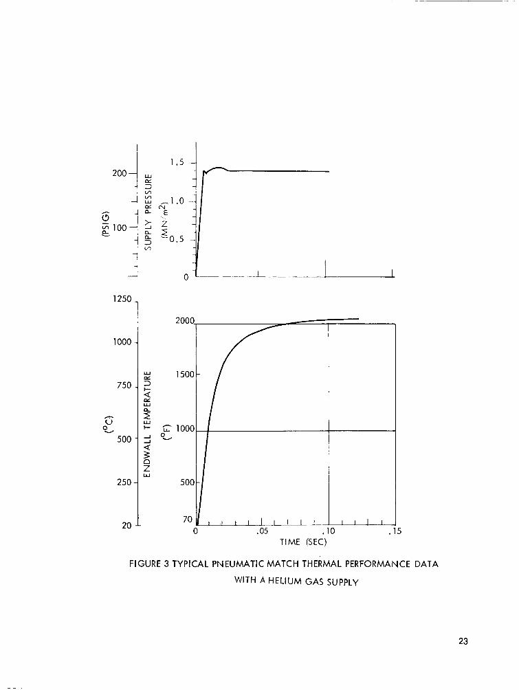
Although there is continuous flow into and out of the resonant cavity, a portion of the gas remains trapped a t the closed end where it is subjected to a succession of waves producing periodic compres- sion and rarefaction of the trapped gas. This periodic compression and expansion of the gas, within the rigid cavity of the resonance tube, produces irreversible temperature increases a t the endwall of the cavity sufficient to ignite pyrotechnic materials. The performance of a typical gaseous helium system is shown in Figure 3. When a helium gas supply pressure of 1.5 MN/m2 (220 psig) is supplied to the pneumatic match as shown in Figure 3, the result is the near optimum temperature output shown.
Historically, the principle of aerodynamic heating of gases in resonance tubes had been generally overlooked by early investigators, such as Hartmann ( l ) , who were mainly interested in the acoustic power generation capabilities of these tubes. Sprenger (2) in 1954 was able to obtain endwall tem- peratures of almost 425°C in m e of his air powered resonance tubes. His tube, however, was over 10 cm in length and took several minutes of steady state operation to reach these temperatures. Thompson (3) and Kang (4), along with Broucher and Moresca (5) have attempted, with some limited success, to theoretically predict and analyze the operation of the resonance heating principles. They have, in general, been able to obtain only order of magnitude estimations of the heating which is experiment- ally observed.
Beginning in 1968, after preliminary independent research and developmental efforts showed promis- ing performance, additional work was conducted toward applying this principle to ignition of explos- ive ordnance, under contract to Picatinny Arsenal. In initial work, the ignition of nitrocellulose was accomplished with an ignition device less than 6 cm in length called the pneumatic match. This pneu- matic match, as improved under continuing programs, provides significant improvements for safe, sim- ple, nuclear hard, shockproof, reliable and inexpensive Safing, Arming and Fuzing of components and
2
systems. Primary explosives were ignited in less than 10 ms with helium a t 1.4 MN/m2 (200 psig). Endwall gas tempeatures of over 1250°C were obtained in less than 35 ms with a device 3 cm in length.
The feasibility of adapting the pneumatic match to a restartable solid propellant rocket motor en- gine ignition system was demonstrated by Rakowsky and Marchese, under contract to the U. s. Army's Advanced Ballistic Missile Defense Agency in early 1970. An improved resonance tube de- sign incorporated into the pneumatic match successfully ignited an explosive/pyrotechnic train which resulted in the ignition of M-1 propellant in a simulated rocket motor ignitor.
The objective of this present study was to develop and demonstrate an inexpensive, safe and fool- proof ignition system concept for solid propellant rocket motors. Although first proposed for demonstration in a sounding rocket, this system has broad potential applications in all solid propellant motor vehicles in first stage ground launch, or in upper stages utilizing fluidic program- mers. The advantages of such an ignition system would be improved safety and decreased cost without degrading re1 iability.
The flueric initiation concept, as established by this program, is to pressurize 100 m (330 feet) of tubing which i s sealed just outside the rocket motor by a check valve with a hand-driven pump. The check valve releases a t a preset pressure of about 0.45 M N h 2 (65 psig). The air flow from the 100 m reservoir provides energy for the pneumatic match producing temperatures a t the end of the cavity sufficient to ignite pyrotechnic materials in less than one second. The feasibility of the concept of a flueric sounding rocket ignitor has been demonstrated both analytically and experi- mentally in this program. Experimental verification of the margins of operation was obtained by igniting nitrocellulose and BKN03 with the flueric ignitor over a range of operating parameters.
3
LIST OF SYMBOLS AND UNITS
The following is a list of the system parameters and the symbols used to designate them throughout the discussion in the report. Definitions of some of the important terms as used in .this report are:
Nozzle - a simple axisymmetric convergent, under expanded, sonic flow passage aligned to direct the gas flow into the resonance tube.
Chamber - an interaction region between the nozzle and the resonance tube where the nozzle j e t flow couples with the resonance tu'be flow to create the instability necessary to drive the tube into resonance.
Vent - the portion of the chamber in which the supply gases are allowed to exit into the vent tube.
Endwall - the closed end of the resonance tube where the temperatures are greatest and where the ignition takes place.
A*
d d D Y L P m
'amb pc
R R S t
TW
T O v W
speed of sound nozzle area vent area excitation nozzle exit diameier diameter of transfer tubing piston diameter (pump) ratio of specific heats (Cp/Cv) length of transfer tubing resonance tube length molecular weight ambient pressure chamber pressure supply flow pressure gas constant universal gas constant nozzle ex i t to resonance tube separation time endwall surface temperature supply flow temperature volume of transfer tubing mass flow rate through nozzle
4
3. I NSTR U MENTATION Ij The instrumentation used in the test evaluation of the energy source was a Pace Model P3D differential pressure transducer and a Model CD25 indicator which monitored the gas pressure on each side of the check valve. A similar transducer was located downstream of the relief valve to monitor the actual gas pressure supplied tothe nozzle of the flueric ignitor. These pressure transducers were statically calibrated against standard Bourden tube pressure gages. The response of these transducers is flat to 1000 Hz.
Resonance tube performance was evaluated with the use of chromel-alumel thermocouples fabri- cated from 80 B m diameter wire (0.003 in). The thermocouples, sealed into the end of the reson- ance tube with a ceramic cement, provided a nearly adiabatic measurement of the resonance tube endwall temperature. Although some heat is lost by conduction through the tube material and the thermocouple wire, the error is estimated to be less than 15%. The response time for these thermo- couples is less than 20 ms. For some ignition studies, thermocouples were placed a t the resonance tube/propeIlant ignitor interface as well as on the propellant ignitor material (BKN03). Other ignition tests were conducted by visually determining that the propellant ignitor material had been ignited.
Permanent recordings of the pressure and temperature measurements were made on a sixteen chznnel high speed oscillographic recorder (Honeywell Visicorder Model 191 2). The frequency response of this recorder is 3 kHz. For most test evaluations the time base used was 0.05 s per division.
5
4. DESCRIPTION OF APPARATUS
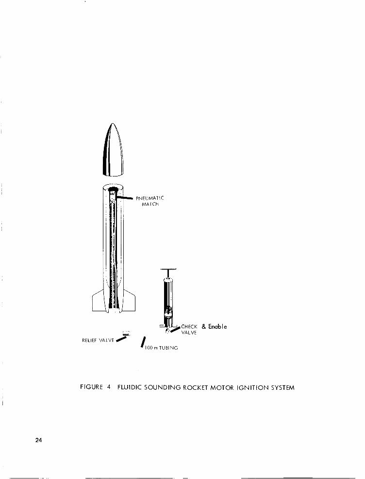
The ignition system concept developed for this study is shown schematically in Figure 4. When the operator wishes to launch a rocket he moves the selector valve to the ENABLE position and begins to exert force on the pump. The check valves allow the supply line gas pressure to increase with each downward stroke of the pump. The relief valve remains closed until the gas supply pressure reaches the ignitor operating pressure. It then opens and remains open, discharging the volume of supply gas from the tubing into the ignitor. For safety considerations, leakage can be built into the system so that the operator will be unable to ‘cep the supply volume charged atpressuresclose to the relief valve opening pressure. The ignitor converts the gas flow energy into thermal energy through the resonance heating effect. Generation of sufficient thermal energy to cause ignition of the propellant ignitor interface is assured by the proper ignitor design. The interface material accom- plishes the ignition of the propellant ignitor material by being in close contact with it. The experi- mental apparatus can be divided into three distinct areas: the pneumatic match, the energy source including the transfer tubing, and the propellant ignitor.
4.1 PNEUMATIC MATCH
The pneumatic match, flueric ignitor, shown schematically in Figure 5, consists of a nozzle, a resonance tube, a vent tube, and a propellant ignitor interface - nitrocellulose.
Nozzle. - Pneumatic match nozzles are simple, convergent noLzles designed to produce the proper je t cell structure necessary to obtain resonant heating. Since the nozzle diameter and pressure ratio across the nozzle influence the length of the jet cells, these two parameters may be used to deter- mine the proper separation distance between the nozzle and the resonance tube. For this applica- tion the nozzle diameter also determines the rate a t which the gas supply pressure drops when the valve opens. If the pressure drops too quickly (too large a nozzle) resonance heating will take place for a time too short to develop ignition temperatures.Nozzles used for these investigations had diameters of 0.6, 0.9 and 1.2 mm (0.024, 0.036, 0.047 in).
Resonance Tube. - Resonance tubes of various lengths, internal shapes and materials were evaluated to determine the optimum configuration for this application. Several of the tubes evaluated are shown in Figure 6. Initial tubes were made from a thermally insulating transfer molding material (Hysol MG5F, a glass filled epoxy) in order to minimize the heat transfer loss. Later tubes were made from nitrocellulose. Tube lengths ranged from 7.6 mm to 21.6 mm (0.30 to 0.85 in). The internal tube diameter ranged from 0.6 mm to 1.6 mm (0.025 to 0.062 in).
Resonance Tube/Nozzle Alignment Margin Determinations. - A three degree of freedom micro- positioner was used to determine the alignment requirements of the nozzle and the tube in a l l three linear dimensions: horizontally, vertically, and axially. This mounting apparatus allowed precise translation of the resonance tube along three orthogonal axes with respect to the nozzle while maintaining the axes of the nozzle and tube in parallel.
Vent Tube. - The vent tube, as shown in Figure 5, allows the air being discharged from the chamber to leave the ignitor. Since resonance heating i s a flow phenomenon no resonance heating is possible
6
without some means of venting. One parameter which determines the location of the je t cell structure i s the pressure ratio across the nozzle, Po/P,. With an unrestricted vent where Pc = Pamb, the ratio is simplyP,/P,,b. If the vent area is finite, which it must be for this system, then Pc > Pamb and the pressure ratio is reduced. Numerous vent areas and vent configurations were evaluated. Since the ignitor in this system is located inside a rocket motor, the venting must take place through a tube. The optimum vent tube configuration found was a coaxial tube with an inner diameter of 17 mm (0.7 in).
Propellant Ignitor Interface thermal energy associated with resonance heating of the air into sufficient heat and hot particles to ignite the propellant ignitor (BKN03). Since the resonance tube concentrates the heat generated a t its closed end, a nonconsumable type tube must be closed off with approximately 20 mg of nitrocellulose. A nitrocellulose resonance tube is entirely consumable and eliminates the need for an additional interface material. Therefore, a consumable type was selected for this design.
Nitrocellulose. - A propellant ignitor interface is used to convert the
4.2 ENERGY SOURCE
The energy source shoJvn in Figure 7 consists of a mechanical hand pump, check valves to allow the supply volume to be pumped up to the operation pressure of the ignitor, and an abort-enable valve to release the supply pressure bypassing the ignitor, an in line filter, the pneumatic tubing which acts as a supply volume, and a reliaf valve.
Hand Pump. - The hand pump used for test evaluations was a simple air cylinder with a pump handle attached. The bore diameter was 35 mm (1.375 in) with a 51 cm (20 in) stroke. The ai r cylinder was used as a standard single stage hand pump.
Check Valves. - - The two check valves control the output or exhaust port of the air cylinder. They allow the compressed air to enter the transfer tubing on each downstroke and the filling of the cylinder with air a t atmospheric pressure on each upstroke. The valves used were Hoke Model 621 1 F2B (ball-type) with a cracking pressure of 2kN/m2 (0.3 psig).
Abort-Enable Valve. - Any standard two position pneumatic valve (i.e., Hoke Model 458 spring closing toggle valve) can be employed for this application. I t s purpose is simply to divert or dump the supply air pressure quickly and safely a t any time and a t any stage prior to the rocket engine ignition.
In Line Filter. - An in line f i l ter (Hoke Model 6310 F4B) with a 5 pm(.?OO pinches) filter element was used to prevent particles from clogging the ignitor nozzle. The in line filter is placed upstream of the supply volume so that it offers no resistance to the flow of gas out of the relief valve.
Supply Volume. - The supply volume is made up of a length of standard plastic pneumatic tubing. The volume of the 100 m (330 ft) long line with an internal diameter of 6.4 mm (0.250 in) is 2944 cm3 (194 in3).
7
Relief Valve. - - An adjustable relief valve (Norgen #V96-100-NNK-AU) was used to release the supply gas a t the desired pressure. This valve may be set to release a t pressures between 1.4 kN/m2 and 14 MN/m2 (2 to 200 psig). Once the valve opens it does not close again until the pressure drops to below 10% of the opening pressure. Thus, i t will stay open long enough to insure ignition but will automatically reset after each operational cycle.
4.3 PROPELLANT
Boron potassium nitrate (BKN03) is typically used as an ignitor in solid propellant rocket motors. Once ignited the flame produced is adequate to ignite most solid propellants. Atlantic; Research F-ND 2M and 2A cylindrical pellets of BKN03 were used for this investigation. Each 2M pellet was 3 mm (0.125 in) in diameter by 2.5 mm (0.100 in) long and had a mass of 45 mg. The 2M pellet of BKN03 was positioned against the nitrocellulose resonance tube end. The 2A pellet was used in the propellant basket.
5. PROCEDURE
The basic procedure used (to accomplish the objective of this program) to establish the feasibility of flueric ignition of sounding rocket motors was to determine the pressure/fIow/tir'ie requirements of the flueric ignitor and develop a power supply to provide this input.
5.1 PNEUMATIC MATCH
Pneumatic matches were evaluated to establish their ternperature/time output characteristics for various pressurehime inputs. Thermocouple data were used to determine the thermal output. The thermal output was then compared to the minimum ignition requirements of the nitrocellulose resonance tube to determine which configurations were applicable.
Nozzle. - To determine the pressure/time output characteristics test runs were made with nozzles whose diameters were 0.6, 0.9 and 1.2 mm (0.024, 0.036 and 0.047 in). Since the nozzle diameter influences both the supply pressurehme output to the resonance tube and also the thermal out- put performance, tests were conducted to determine the pneumatic match input/output characteris- tics for each nozzle.
Resonance Tube. - - Three basic resonance tube shapes were evaluated: cylindrical, tapered, and stepped. Previous comprehensive developmental efforts on resonance tube optimization under con- tract to the Army's Picatinny Arsenal and the Army's Advanced Ballistic Missile Defense Agency indicated that the stepped'tube produced very fast temperature increases and much higher endwall temperatures than the other tube configurations tested. However, since this work was directed toward military applications and used a gas other than air as a supply gas a t 2 MN/m2 (300 psig), the superiority of the stepped tube had to be verified with low pressure air. The thermal output of the three tube types was obtained for air supply pressures up to 1 MN/m2 (150 psig).
Pneumatic match configurations were developed to provide endwall temperatures with an adequate excess of thermal energy to ignite propellants. A goal of a t least 300°C was used. Twenty-two different type resonance tubes were evaluated during this program. Of the 66 possible combinations of tubes and nozzles, 44 were evaluated. Based on these evaluations, a tube was selected to pro- vide sufficient thermal output with a large excess of thermal energy a t a minimum gas supply pressure.
Nozzle/Resonance Tube Alignment Margin Determination. - An assessment of the alignment require- ments of the nozzle and resonance tube along three axes was made with the three-axis micro- positioner assembly. Steady state temperatures produced by a 2 cm long tube after 1 s operation a t a fixed supply pressure of 0.7 MN/m2 (101 psig) were recorded as the alignment was adjusted in steps of approximately 0.13 mm (0.005 in). Similar data were obtained for a 1 cm long tube with a supply pressure input which i s obtained when the relief valve opens and discharges 1960 cm3
2 of air a t a pressure of 0.4 MN/m (60 psig) through an open nozzle. For these tests the maximum temperature (transient) was recorded. These tests were conducted with both the 0.9 mm and 1.2 mm diameter nozzles. The alignment was adjusted in steps only over the range in which resonance heating took place. The alignment which produced the highest endwall temperatures was chosen as the configuration to be used for ignition feasibility tests.
9
Vent Tube. - - Since the vent area determines an important operating parameter, the nozzle pressure ratio, i t s limits were evaluated. The largest vent area possible occurs when the nozzle and resonance tube are free standing as i s the case when tested in the three-axis microposition apparatus. The vent area, in this case, is the circumference of the resonance tube times the separation distance. The system concept developed for this application requires a vent tube which has a fixed area and a length corresponding to the rocket motor dimensions. The cross-sectional area of the vent tube evaluated was 0.32 cm2 (0.05 in2). I t s length was varied from 0 to 1 m (39 in) in order to deter- mine if the ignitor would operate with long vent tubes as would be required in sounding rocket motors.
Propellant Ignitor Interface - Nitrocellulose. - Ignition characteristics of nitrocellulose and BKN03 samples were determined by Differential Thermal Analysis (DTA) using a Dupont Model 900 analyzer with a differential scanning calorimeter. The reference was an empty pan. These data were used to determine a minimum temperature a t which an ignition could be expected. Results of the resonance tube thermal output tests were compared with these requirements to choose a suitable ignitor configuration. Since DTA is a dynamic measurement and the rate of heating (10°C per minute) affects the onset temperature, actual ignition tests were conducted to verify the ignitor choice. Ignition tests were conducted with the ignitor supplied with various combinations of supply volumes and initial gas pressures. These tests were compared with corresponding temperaturehime traces to establish an ignition criterion which included both temperature and time. It was possible with these tests to determine the effect which changes to supply volume and/or nozzle diameter would have on the system performance.
Propellant Ignitor Interface Margin Determination. - A preliminary determination of the margins of ignition was accomplished. At the optimum alignment position for each of two nozzles, a succession of runs was made a t gas supply pressures which were increased until an ignition occurred. The s?paration distance was then varied from 1.2 mm to 5.0 mm to determine i t s effect on the gas pressure required for ignition and to compare ignition data with corresponding thermocouple data.
Resonance Tube Margins. - The effect of low ambient temperatures on the ignition capabilities of the ignitor system was evaluated by placing an ignitor system in an environmental chamber maintained a t -40°C (-40°F). The system was modified so that the supply gas could also be cooled prior to an ignition attempt. The supply volume was connected to a solenoid valve on the outlet side and to a bottle of compressed air on the inlet side. The supply volume was charged to a pressure slightly higher than the required operating pressure and closed with a valve. After 7200 s (2 hours) a t -40°C the gas supply pressure had dropped to the desired operating pressure and the solenoid valve was opened. This test is more stringent than that which would be encountered in an actual ignition attempt a t -40°C ambient because the gas is allowed to cool prior to test. The gas would definitely be considerably warmer due to the heat of compression.
Ignition Design Development. - Based on the results of the above investigations, an ignitor was designed and developed to optimize the performance variables and program requirements. Of prime concern was the incorporation of adequate marging and meeting the size envelope of the rocket motor.
10
5.2 ENERGY SOURCE
Hand Pumps. - Various hand pumps were evaluated to determine if they were appropriate for this application. These pumps had piston areas ranging from 1.6 cm2 (0.25 to 2.4 in2) and stroke lengths from 15 to 51 cm (6 to 20 in). These pumps were evaluated experimentally arid w-vlylic- ally to determine the maximum pressure output for a 670 N (150 Ib) force input. Experimental and analytical evaluations were conducted to determine the maximum pressure which could be obtain- ed in a pump system where compressed air was allowed to bleed off through nozzles of various diameters. The gas supply pressure/flow requirements of the penumatic match ignitor were com- pared to these test results to determine the type of power supply necessary for this application. Combinations of hand pumps and supply volume were evaluated analytically and experimentally to determine an effective configuration which would provide the necessary pressure/time output with a minimum expenditure of the operator's energy and time.
Check Valves. - The effect of the cracking pressure of the check valves on the pump's output pressure and flow characteristics was experimentally and analytically determined.
Abort-Enable Switch. - The abort-enable switch was experimentally evaluated to determine the time required to dump the supply of compressed air to a safe level.
In-line Filter. - The in line filter was experimentally evaluated to determine i t s effect on the pressure/time and flow output characteristics. This was accomplished by comparing test runs made with and without the filter in line.
Supply Volume. various diameters and lengths. The inner diameter of the tubing was either 3.2 or 6.4 mm (0.126 or 0.251 in). The length of tubing was varied from 75 to 100 m (200 to 330 ft). This provided gas suppr/ volumes of 488, 735, 1960 and 2944 cm3.
- The gas supply volume was varied by using polyethylene pneumatic tubing of
Relief Valve. - - Relief valve requirements and operating characteristics were experimentally evaluated. Tests were run with the relief valve set to release a t pressures from 0.3 to 1.4 MN/m2 (43 to 200 psig) with the various supply volumes and nozzle diameters. These tests were used to establish the ignition pressure/time margins. To test the repeatability of the relief valve, ten runs
3 were made at each of three pressure settings. The gas pressure in a 2944 cm supply line was slowly increased until the valve opened.
Energy Source Margins Determinations. - Flueric ignitor assemblies were analytically and exper- imentally evaluated with complete hand pump operated supply systems to establish the feasibility of the flueric ignition concept by actually igniting BKN03 pellets. Subsequent efforts were directed toward experimentally and analytically defining the operating margins of the ignition system.
5.3 PROPELLANT
Ignition characteristics of BKN03 samples were determined by Differential Thermal Analysis (DTA) in the same manner as the nitrocellulose. The methods of interfacing the BKN03 pellets and the ignitor was determined experimentally.
11
6. RESULTS AND DISCUSSIONS
6.1 Pneumatic Match
The pneumatic match can ignite primary explosives in as little as 5 ms and achieve temperatures in excess of 1200°C in 35 ms. This extraordinary performance is obtained only with an optimum configuration operating with relatively high pressure gas. To design the pneumatic match to allow operation with a low pressure air supply required modifications of the ignitor geometry. The use of low pressure air as the supply gas lowers the maximum temperature and lengthens the time response. Therefore, the thermal output characteristics of the pneumatic match were closely matched to the ignition requirements of the nitrocellulose resonance tube.
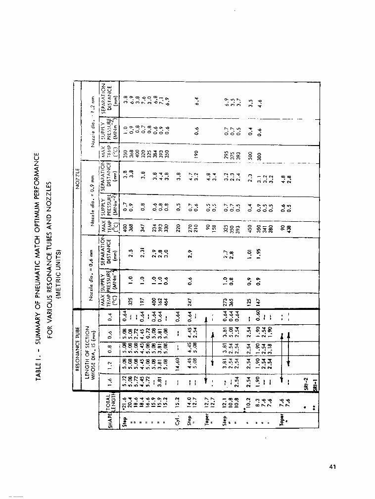
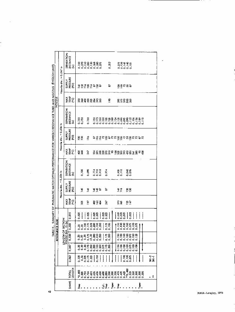
Table I presents (in SI units) a summary of the gas pressure and separation distance necessary to obtain the maximum thermal output for each type of tube with each of three nozzles. The tubes are arranged in this table in order of decreasing length. The dimensions of the tubes are tabulated and used to identify them. For example: the first tube (designatedSRI 2) has a total length of 21.6 mm which is made up of five cylinders of different diameters. The first cylinder is 1.6 mm in diameter and is 5.72 mm in length while the last cylinder in the tube has a diameter of 0.4 mm and is .0.64 mm in length. This resonance tube was evaluated with two nozzles, 0.9 mm diameter and 1.2 mm diamter. The best temperature performance for each nozzle i s given in the table along with the corresponding pressure input and separation distance. With the 0.9 mm nozzle,
Table II presents the identical data in the same format but in English units.
400°C was generated a t a supply pressure of 0.7 MN/m 2 and a t a separation distance of 3.8 mm.
The tube which produced the highest temperature of any tested during this program is 10.2 mm in length and when supplied by a 1.2 mm diameter nozzle a t 0.4 MN/m2 (55 psig) produced temperatures of 500°C. This tube, designated SRI 1, was subsequently tested to determine the minimum pressure required to cause ignition. It was also evaluated a t higher pressures a t various vent areas to determine i t s optimum performance. The optimum performance (shown in Figure 8) occurs a t a vent area of 0.1 cm2 (0.016 in2). The maximum temperature exceeded 800°C for this configuration which was subsequently used for the final design.
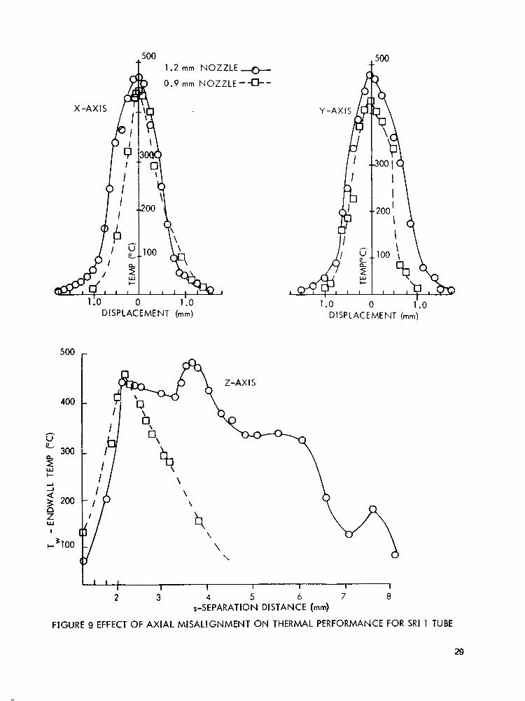
Nozzle/ Resonance Tube Ajignment Margin Determination.-Efforts to establish the margins of operation of the ignitor were concerned with the individual system components and their relation- ships to other components. Angular misalignment of the nozzle and resonance tube had been previously found to be detrimental to proper operation. The effects of axial misalignment were measured along three orthogonal axes, X, Y, and 2, where Z corresponds to the 5eparation distance between the nozzle and the resonance tube. The results are shown in Figure 9 for both the 1.2 mm and 0.9 mm diameter nozzles with the SRI 1 resonance tube, Figure 6. The effect of misalignment i s seen to be a lowering of the maximum temperature attainable. The larger (1.2 mm diameter) nozzle i s found to exhibit a somewhat wider range of operation with respect to X and Y axis misalignment than the smaller nozzle. With respect to the separation distance (Z-axis alignment), it has more than twice the operating range than the small (0.9 mm diameter) nozzle.
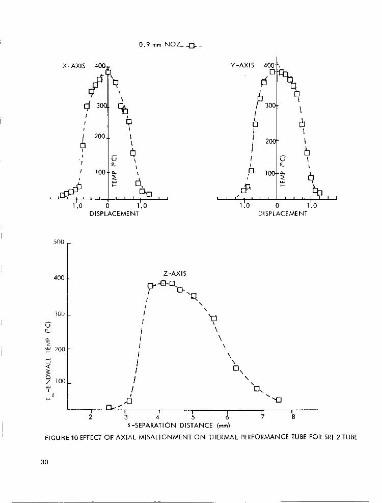
Similar data shown in Figurelotaken with a 2 cm long resonance tube (SRI 21, shown in Figure 6, provides a comparison of the effect of the length of the resonance tube. For this longer tube with the 0.9 mm nozzle, there is a slightly wider performance range with respect to X and Y axis misalignment although the maximum temperature is lower for this tube with the 0.9 mm nozzle. The range of usable separation distance is improved considerably with this longer tube.
12
Varying the separation distance was shown (Figure 9) to effect the maximum temperature obtainable. Since ignition of materials (such as nitrocellulose) is dependent on the time history of the thermal input rather than the maximum temperature, further insight into the ignition margins may be obtained with reference to the data presented in Figure 11. These data, taken with thermocouples, show the actual temperaturehime histories a t six separation distances in intervals of 0.5 mm. For these tests the S R I 1 ignitor was tested with a 1960 cm3 volume with the relief valve set to discharge
temperatures of a t least 325°C were obtained. The time that a t least this temperature is maintained varies with the separation distance from 0.5 sec to 2.0 sec with the maximum times occuring a t a separation distance of 3.5 and 4.0 mm. Peak temperature occurred a t 3.5 mm.
I
a t 0.5 MN/m 2 (73 psig). The large nozzle (1.2 mm dia.) was used. At each separation distance
The supply pressure can effect the separation distance since it determines the location of the instability region of the jet. Additional insight into the effect of the initial supply pressure may be obtained with reference to the temperaturehime traces shown in Figure 12. These traces generated by an SRI 1 ignitor a t a separation distance of 3.5 mm demonstrated how the time at ten ieratures above 325°C increases with increasing supply pressure to about 3.5 seconds a t Pi = 0.60 MN :;:;2 (87 psig). At pressures above this, only a time delay is the result. The test ignitor shown in Figure 5 operated only when the pressure ratio across the nozzle was between 3 and 6. Thus no further improvement in temperaturehime performance was expected with the test ignitor for supply pressures higher than 0.6 MN/m2 because it would not operate under those conditions. The ignitor used in the final design however, would operate a t high supply pressures because it was designed to reduce the pressure ratio across the nozzle by choking a t the vent.
Vent Tube.-The ignitor used to generate the data of Figures I 1 and 12 was improved by decreasing the vent area, as shown in Figure 8. These data were obtained with P, = 0.7 MN/m2 to determine the optimum thermal output which could be expected. As the vent area is reduced, the maximum temperature increases and peaks a t about 0.1 cm2 (0.015 in2). The output duration is shorter for
2 this vent area because it has an operation band which includes pressures higher than 0.7 MN/m . The larger vent configuration does not operate a t the higher pressures note the time delay) but holds the thermal output longer. For vent areas smaller than 0.08 cm one obtains very fast response but loses thermal output due to being at the extreme of the operation range. Therecrt, for optimum performance, the ignitor should incorporate a vent area of approximately 0.1 cm' a t a separation distance of 2.5 mm (0.100 in) and an initial pressure of 0.7 MN/m2. It was demonstrated that this configuration will provide 800"C, many times the output needed to ignite the nitrocellulose even at ambient temperatures of -40°C.
1
To evaluate the effect of a long tube as a vent, corresponding to the operation of the flueric ignitor within a rocket motor, ignition tests were run with 6.4 mm I.D. tubing as the only vent. It was found that lengths over 1 m could be attached to the ignitor without affecting the ignition performance. Subsequent evaluations indicated that the optimum venting method was a co-axial tube completely surrounding the ignitor. With such a vent tube the significant \rent area becomes the area of the ignitor's vent holes.
Propellant Ignitor Interface - The results of differential thermal analysis of nitrocellulose showed identical traces for tests ;de in a nitrogen and an a i r atmosphere. They both indicated an exotherm starting a t 150°C. A change in the slope on the exotherm occured a t 167°C. The same effect was noted on a literature thermogram in the Stadtler Index for nitrocellulose. In that thermogram obtained on a nitrocellulose sample from Hercules Company, initial decomposition was noted a t 165" -203"C, followed by ignition a t 203" -242°C.
13
Propellant Ignitor Interface Margin Determinations. The pressure required to cause ignition was determined for the 1.2 mm diameter nozzle and the 0.9 mm diameter nozzle in a large vent configuration. The minimum pressure to obtain ignition with the 0.9 mrn nozzle was 0.41 MN/rn2 (60 psig) whereas it was only 0.31 MN/m2 (45 psig) for the 1.2 mm diameter nozzle. The separa tion distance required a t this lower pressure and the larger nozzle was 1 mm larger than that for the higher pressure and the smaller nozzle ptessurc must pass through the optimum pressure ranye if it starts a t an initial pressure greater than the optilnum. It was found that with an initial pressure of 0.5 MN/m (72 psig) a range of separa
tion distance of almost 2 mm was possible wi;i) the 1 2 mm dialneter nozzle. To obtain a compara hle range for the 0.9 mm nozzle, a pressure of 0.6 MN/m (87 psig) i s required.
Ignitor Margins. large vent SRI 1 ignitor was evaluated at temperatures of -40°C. All tests conducted a t initial
2 suppl'y pressures o f a t least 0.60 MN/rn produce considerably higher temperatures a t higher pressures and the smaller vent area.
No upper limit on pressure was found because the
2
2
The effect of cold temperature operation on ignition characteristics of
(87 psig) produced ignitions, ;,veri though the ignitor will
Ignitor Design Development. - An ignitor was designed based on the results of the experimental test data which indicated that the largest margin for ignition would occur with a reduced vent area. A preliminary design of an ignitor which satisfies the ignition requirements and the envelope requirements is s'lown in Figure 13. It consists of six parts fastened together by screw threads or co m pressio n .
The final design (Figure 14) of the ignitor for this program incorporates the same provisions for attaching the vent and supply tubing but eliminates all screw type connections. It was determined that nitrocellulose wil l bond to itself very well with the addition of just one or two drops of solvent (i.e., acetone). Thus the resonance tube which will be a molded part will be cemented in place in the molded holder simply by wetting i t s surface with solvent and placing it into i t s mating hole. Similarly the molded BKNO3 holder will be loaded and placed into the other holder which will have been just wet with solvent. The bonding accomplished in this way b quite strong and provides a very good seal.
Detailed drawings of the three nitrocellulose components are shown in Figures 15, 16 and 17. It should be noted that the resonance tube has a ignitor interface.
1.0 rnm endwall which act as the propellant/
In order to enhance the consumption of the ignitor, it is recommended that BKN03 powder be mixed with the nitrocellulose for all three molded parts. Ignition tests have shown that the addition of BKN03 to the resonance tube greatly enhances the flame transfer to the BKNO3 pellets in the holder. A 35% mixture by weight i s adequate for this application although this may have to be varied due to the many different types of nitrocellulose available. In general, the less the nitrocellulose is nitrated, the more BKN03 should be added to enhance flame spreading. High speed motion pictures of test firings indicate that flame spreading is quite acc?ptable even with no BKN03 added to the nitrocellulose.
6.2 ENERGY SOURCE -
Hand pumps - The energy source was designed to provide an initial gas supply pressure of approx- imately 0.7 MN/m2 (101 psig). It is important that the supply pressure remain within the particular optimum operating (resonance heating) range of the ignitor used for a minimum of 1.5 sec. As shown in Figure 18 a pump piston diameter of 35 mm (1.38 in) will produce a pressure of 0.7 MN/m 2 . wlth a force input of 670 (150 Ibf). A pump with a smaller diameter piston will also be
1 4
able to produce the required pressure but will take more strokes to achieve it. A larger diameter piston is not useful for this application because a force greater than that which could be provided by an average person (670 N) would be required to obtain 0.7 MN/m2.
An alternate approach to the power supply, wnich eliminates the need for a relief valve, is the use of a pump which produces a greater mass flow of air than can be passed through the nzozle. This causes the pressure behind the nozzle to increase but was found to be impractical.
Check Valves. -The pressure of the air which enters the supply tubing is directly affected by the cracking pressure of the check valve. The pressure produced a t the pump exhaust port is reduced by the value of the cracking pressure. Additionally, on each upstroke of the pump's piston the cylinder refills to atmospheric pressure minus the cracking pressure of the input check valve. Thus check valves with very low cracking pressure ( 2 KN/m2) were utilized.
Abort-Enable Switch.- Since the ignitor will not function a t pressures below 0.2 MN/m2 (30 psig) the switch had to be able to safely dump the pressure from 0.7 MN/m2 to 0.2 MN/m2 in less than 5 seconds. Testing indicated that this could be accomplished within 3 sec.
- ImLine Filim- The 5 micron in-line filter located near the hand pump did not affect the pressure/time or flow characteristics a t the relief valve.
Supply Volume. - Tests conducted to determine how long it would take to pump a 2944 cm 3 supplv
line to 0.7 MN/m2 (101 psig) indicated that it would require approximately 30 seconds. By contrast it takes less than 15 seconds to pump up a 1960 cm3 (119 in3) line to 0.5 MN/m2 (73 psig). It should be noted, however, that it i s not necessary to pump continuously for these times. The operator may stop briefly and then resume without losing much air pressure. For safety considerations leakage can be built into the system so that the operator will not be able to keep the volume charged a t pressures close to the relief valve opening pressure.
Relief Valve. - Although the ignition device is relatively insensitive to supply pressure variations above 0.5 MN/m2 (73 psig), the repeatability of the relief valves was investigated. The relief valve was adjusted to discharge a t 0.70 MN/m2 (101 psig), 0.55 MNm-* (80 psig) and 0.41 NMm-2 (60 psig). The following table lists the initial pressure, the ten run average and the standard deviation, (T , for the ten runs a t each pressure.
Initial Pressure Ten Run Average Standard Deviation
MNm-2 Psig M N m-2 Psig MNm-2 Psig
0.700 101.5 0.695 100.1 0.0030 0.5 0.552 80,O 0.550 79.8 0.0026 0.4 0.4 14 60.0 0.412 59.8 0.0020 0.3
Energy Source Margin Determinations- The rate a t which the supply pressure decays once the relief valve is opened is a function of the supply volume nozzle diameter and initial pressure and may be analyzed with respect to fluid dynamic principles of gas flow through a nozzle. It can be shown from the mass continuity equation and the ideal gas laws that the pressure a t any time after the valve opens, Po, may be related to the initial pressure Pi by the following:
15
i
po = Pi exp ( - y R T o ( - - ) 2 - Y +1 Y+1 Y -1
I
If we asskme the initial pressure Pi = 0.7 MN/m2 tiien an ignition
A" t) v (1)
criterion of a t least 2 sec may be met with either the 1.2 mm or the 0.9 mm nozzle and either the 75 m or 100 m line length with 6.4 mm ID tubing. However, with the 3.2 mm ID tubing only the combination of longer length tubing and the small diameter nozzle will meet the ignition criterion.
Ignition System -- Testing. -The results of testing the complete ignition system showed that ignitions were obtained within 30 seconds after beginning to pump. High speed (200 frames/s) photographs of several ignitions showed very good and uniform flame spreading. Figures 19 and 20.)
6.3 PROPELLANTS
The DTA results for BKNO3 in nitrogen indicated endotherms a t 1 2 9 (transition from the normal high temperature form to a metastable high temperature structure) and 300°C (melting). These two transitions agree with literature values (Handbook of Chemistry and Physics), forBKN03by itself. Several exotherms were noted starting a t :250"C, 425"C, 435°C and a major exotherm starting a t 475°C. As expected, in air, endotherms were again noted a t 129°C and 330°C. An earlier exotherm was noted starting a t about 200°C. Other exotherms appeared a t 410°C and a t 465°C (major).
The BKN03 pellets were placed within a 3 mm (0.125 inch) diameter nitrocellulose holder whose ID was 4.57 mm (0.18 in). This left room to pack BKN03 powder around the pellets. The BKN03 was in direct contact with the 0.64 mm (0.025 in) thick nitrocellulose resonance tube endwall. Thus the burning of the endwall would ignite the powder and pellets which would in turn burn out of their holder and ignite additional pellets in the ignition basket.
16
7. CONCLUSIONS
The objective of this program was to develop, demonstrate and finalize the design of an inexpensive, safe, and foolproof advanced developmental model of an ignition system for sounding rockets. A flueric solid propellant ignitor - the pneumatic match - was developed to operate when powered by a single stage hand pump. The operation of the flueric ignitor is based on aerodynamic resonance heat- ing in closed tubes excited by a free air jet emanating from a simple convergent nozzle. As such it com- pletely eliminates the need for electrical energy and wiring.
Safety is improved with this system, as compared to the commonly used electircal systems, since this system is completely insensitive to stray voltages, EMP and electrostatic voltages. The possibility of inadvertent initiation is virtually eliminated, since the probability of connecting a supply of bleeding pressurized g a s with sufficient energy to achieve ignition is extremely remote. No complicated power supplies, or safe and arm devices are needed. Decreased costs can be achieved through very simple molded parts, and the ability to install the motor’s complete ignition system during manufacture, thereby decreasing motor complexity and eliminating the need for less reliable field installations.
The diameter of the hand pump piston was optimized at 35 mm (5.375 in) because it would allow pressures of 0.7 MN/m2 (100 psig) to be developed for a 640 N (150 Ib) input. Pumps with smaller diameter pistons which could also develop these pressures were not used because they required a long- er period of time to achieve the required pressure.
The minimum supply volume’required for this ignition system is 735 cm3. If the supply tubing length is only 75 m (250 ft), as it could be if this were the desired standoff distance, the 6.4 mm (1/4 in) inner diameter transfer tubing would be required to obtain the necessary supply volume. If a t least 100 m (330 ft) of transfer tubing is used, then the 3.2 mm (1.8 inch) tubing may also be used.
The energy source which used a hand pump and a relief valve was chosen for the final system be- cause to pump a supply line without the relief valve (with an open nozzle) required considerable operator effort. The relief valve offered an inexpensive, reusable and consistent method to minimize the time and effort necessary to effect an ignition. The operator could also stop pumping momentar- ily and not have to start over again. The repeatability of the relief valve was quite good with a stand- ard deviation of less than 3.1 kN/m2 (0.5 psig). These small pressure variations have no effect on the ignitor performance.
Short resonance tubes (1 cm) were found to have performance characteristics comparable to the lar- ger tubes (2 cm). Since it is desirable to have an ignitor which cannot block the rocket motor nozzle after ignition, the short tube was picked for the final ignitor system. The ignitor is made completely of nitrocellulose which burns completely to further eliminate the possibility of nozzle blockage.
The stepped geometry resonance tube was found to be superior to the cylindrical tube in both maximum temperature attainable and minimum time to achieve the maximum temperatures (response time). The tapered tube was not used although it could generate steady state temperatures almost as high as the stepped tube, because i t s response time was 35%sbwerthan the stepped tube. Thus, for this application, where the supply pressure may drop lower than the operating range within 2
17
seconds after the relief valve opens, the tapered tube does not maintain i t s maximum steady state temperature for the required 2 seconds because the tube takes longer to reach i t s maximum temper- ature. The tapered tubes will effect ignition, normally, but does not have the margins which the stepped tube does.
The ignitor separation distance, s, was optimized a t 2.5 mm (0.100 in) because a t this distance the time that the temperature was above 300 "C was longer than 4 sec and the highest peak temperatures (800°C) was obtained. A preliminary ignition criterion which was found to provide an adequate margin was the generation of a t least 300°C for 1.5 sec. There is a minimum initial supply pressure of 0.55 MN/m2 (80 psig) needed to generate 300°C for at least 1.5 sec in the final design configuration. With a higher initial pressure, Pi = 0.7 MN/m (100 psig), the time above 300°C reaches a maximum of 4.5 sec. It was concluded that to insure reliable ignition results and to maximize safety the higher supply pressures were desirable.
2
2 Pressures higher than 0.7 MN/m do not increase this time nor do they increase the maximum temperature unless the vent area is reduced. The time above 300°C remains constant with the only effect of the higher pressure being to delay the start of operation. In fact, by purposely supplying high pressures an accurate time delay may be built into the ignition system. Since it i s actually the pressure ratio across the ignitor nozzle which determines the operating range the effect of operation at high elevations will be to slightly increase the delay time. A minor increase in the time to pump the supply pressure would also be expected a t the higher elevations. With a reduced vent area pressures higher than 0.7 MN/in thermal improvement. There would be no time delay with the reduced vent area.
2 will operate the resonance tube and cause a slight
The 1.2 mm (0.047 in) diameter ignitor nozzle was chosen for the ignition system because it provided higher temperatures and i t s wide operating range as far as alignment and supply pressure was concerned allowed the largest margins of operation. The faster pressure decay with this nozzle, which reduces the time at high temperatures, was offset by the higher temperatures obtainable a t the wider operation range the ability to operate at lower initial supply pressures. With the 1.2 mm (0.047 in) diameter nozzle, alignment of the resonance tube is not a t all difficult. A deviation of t0.25 mril (kO.010) off axis has little effect on the temperature output. The axial alignment (separation distance) may be changed by k 1.1 mm (0.043 in) without appreciably degrading
the performance. However, the use of the same resonance tube with the 0.9 mm (0.036 in) dia- meter nozzle requires a much closer alignment of kO.10 mm (0.004 in) off axis and k0.25 mm (0.010 inch) in separation distance. Standard tolerances of k0.13 mm (k0.005 in) which are easily obtained even in molded parts will therefore have l i t t le effect on the ignitor with the large nozzle but may cause some difficulty with the sm&ller ones. VEnting of the ignitor's supply gas may be accomplished by using an ignitor holder with 2 vents 2.5 mm (0.100 inch) in diameter. These vents exhaust to a 17 mm (0.75 in) ID tube which carries the gas to the base of the rocket. The 3 mm (0.25 in) ID supply line tubing runs inside if the larger return line.
BKNO3 pellets could not be ignited directly by resonance heating. It i s suspected that large a- mounts of heat flux are needed because temperatures of 800°C were obtained without ignitors. An interface material which produces hot particulate matter was found to be required to ignite the BKNO3 pellets. Nitrocellubse was picked as a suitable interface material because it was easily
18
ignited by the resonance heated air and produced the required hot particles. Since nitrocellulose has an igntion temperature of about 170°C only resonance tube configurations which could produce a t teat 300°C were considered for use as an ignitor. The ignitor finally chosen for the system which produced 800°C will provide an adequate margin under a l l environmental conditions.
In the final design of this flueric ignition system, the operator pressurizes a 100 m (330 f t ) length of
then discharges the volume of compressed air through the nozzle and into a stepped resonance tube. The air exists through a vent tube to the atmosphere a t the base of the rocket. The resonance condi- tion described above ignites the nitrocellulose a t the end of the resonance tube, and i t s blrning ignite the remaining pellets in the rocket motor's ignitor basket.
penumatic tubing with a hand pump to a pressure of about 0.7 MN/m 2 (TOO psig). The relief valve
The ignition system, as fabricated, demonstrates the feasibility of the concept of flueric sounding rocket motor igntion by igniting BKN03 propellant over a wide range of operating conditions. Every compon- ent has been found to have adequate margins for both safety and repeatability of ignitions. The com- plete ignitor may be molded or cast, a t a small cost. The energy source system is also simple and cost effective.
19
8. REFERENCES
1.' Hartmann, J. and Troll, B., "On a New Method for the Generation of Sound Waves," Physical Review, Vol. 20, 1922, pp. 719-727.
2. Sprenger, H.S., "Uber Thermische Effekte bei Rezonanzrohren," Mitteilungen aus dem Institute fur Aerodynamik an der E.T.H., Zurich, Nr. 21, 1954, pp. 18-35.
3. Thompson, P.A., "Jet Driven Resonance Tubes," AlAA Journal, Vol. 2, No. 7, July 1964, pp. 1230-1 233.
4. ' Kang, S.W., 'I Resonance Tubes," Ph.D. thesis, 1964, Renssalaer Polytechnic Institute, Troy, N.Y.
5. Brocher, E., Maresca, C., and Bournay, M.H., "Fluid Dynamics of the Resonance Tube," Journal of Fluid Mechanics, Vol. 43, Pt. 2, 1970, pp. 369-384.
20

V A
1
7 w -. T
i I /
. TUBE GE0,METRY
I ' I I /
FLOW c z T x k A* d 0
ENDWALL
?*-I
,' / 1 I..&.
FIGURE 1 CROSS SECTION OF PNEUMATIC MATCH
21
NOZZLE MACH 7 CONICAL WAVE 2
FIGURE 2 PRESSURE VARIATION - SHOCK WAVES
22
1000
750
- V 02
500
250
20
TIME (SEC)
FIGURE 3 TYPICAL PNEUMATIC MATCH THERMAL PERFORMANCE DATA
WITH A HELIUM GAS SUPPLY
23
I PNEUMATIC MATCH
L RELIEF VALVE 0
4 0 0 m TUBING
,CHECK VALVE
& Enable
FIGURE 4 FLUIDIC SOUNDING ROCKET MOTOR IGNITION SYSTEM
i 24
L u m 3 I-
w -I
3 N
Z 0 0 -1 LL
0
25
1: ln
N
2 0 U
U I Z - 1 0
0
v, Z 0
I-
W
U Z
26
W
Z a
27
//
28 FIGURE 8. EFFECT OF VENT AREA
500
400
- V e 300 4
$ 200
W I-
4 -1
n Z w I
c3100
500 1.2 mm N O Z Z L E +
1 :o 0 1 :o DISPLACE ME NT (mm)
tsoo
1 .o 0 1I.o D I SPLACEME NT (mm)
2 3 4 5 6 7 8
FIGURE 9 EFFECT OF AXIAL MISALIGNMENT ON THERMAL PERFORMANCE FOR SRI 1 TUBE
s-SEPARATION DISTANCE (mm)
29
0.9 mm N O S 4- -
16 300- I
I b I 200- I
I
X-AXIS 400
0
\ dl
I I
G \
\
b
d 30( I
I
200
I
400
I
I
-
’ 100 I
& -- 1 .o 4 1 .o
DISPLACE ME NT DISPLACE ME NT
Z-AXIS
I
s -SEPARATION DISTANCE (mm)
FIGURE 10 EFFECT OF AXIAL MISALIGNMENT ON THERMAL PERFORMANCE TUBE FOR S R I 2 TUBE
30
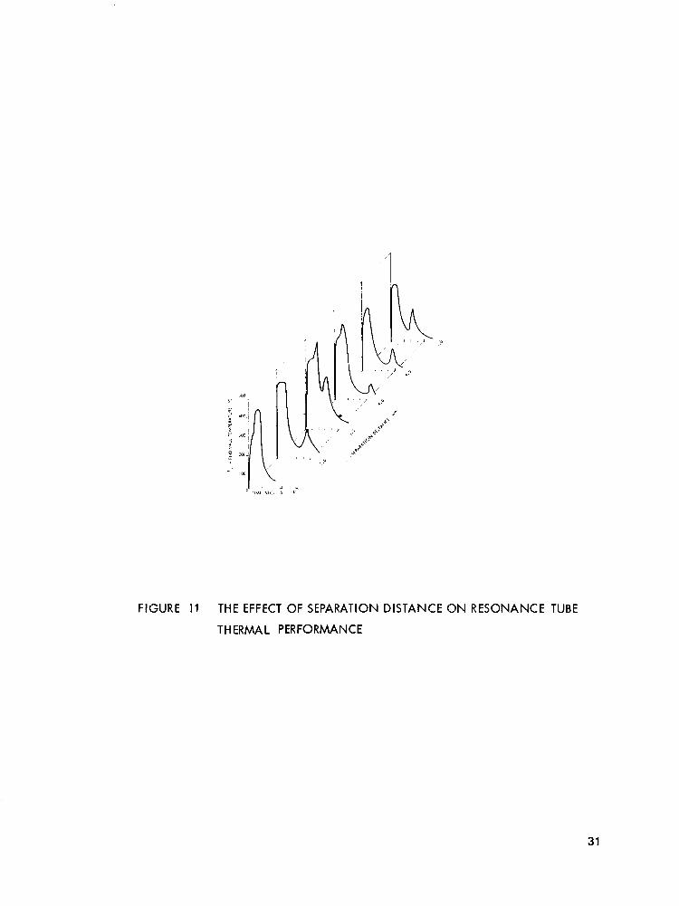
FIGURE 11 THE EFFECT OF SEPARATION DISTANCE ON RESONANCE TUBE
THERMAL PERFORMANCE
31
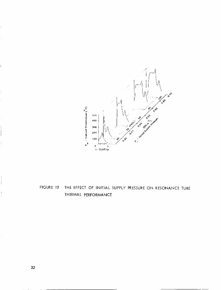
FIGURE 12 THE EFFECT OF INITIAL SUPPLY PRESSURE ON RESONANCE TUBE
THERMAL PERFORMANCE
32
? w -1 J w n
z K w
n a
s 0 n
0 z Y m
(3
z v) w 2 n a 0 t z (3 I- w Y u 0 a c3 z n z 3
t a a z E
-
3
- -1 w K n LL 0 E 0 b w v) v) v) 0 a u 2 a w
3 c3 - LL
33
NOZZLE & HOLDER RESONANCE TUBE (NITROCELLULOSE)
1.5 in . FIGURE 14. CROSS SECTION OF F I N A L SOUNDING
ROCKET IGNITOR DESIGN
34
I
L9'8L r-- 14'91 L
3 LT I I- < 0 -
Q)
8 + I
Y 9 QO
Ln
t 7 (D
f
ci
I
35
W A N N 0 z W UJ I? 3
r- z 0 LL
w K I) (3 - LL
DIMENSIONS IN rnm
0.3 - 6.10 t
1.91
8.89 I r-
--I 5.59 +--
FIGURE 16. CROSS SECTION OF NITROCELLULOSE/BKN03 RESONANCE TUBE
36
Dimensions in mm
c 0' Q) 0 II I
I t i I
5
L- l t O 4 O 3 10.16
FIGURE 17. CROSS SECTION OF NITROCELLULOSEBKN03 PELLET HOLDER
37
PSlG 30C
ioc
100
-2 MNrn
1.5 I-
2 z m
- r-
1 1 .
-I
0 In c
= 1 .o- 0 h 9
8
6 LL
n w
-1 w 2 0.5 n w lx
2 v, w cli L
0 L I I I I I 1 I 1 1 1.5 2.0
I NCH ES
20 ~
30 40 50 MILLIMETER
D - PISTON DIAMETER
FIGURE 18 MAXIMUM PRESSURE DEVELOPED FOR 670N INPUT TO PUMPS OF VARIOUS SIZES
38
/ 0 0
; t -
\\'
v)
E 0
It
7
"
0 II
c.
39
,
- 9 0
41
-
C
I\ P
0 I1
0 0 0 N N
.- 9
.- - t
-
C .- s 0 I1
d .- 0 0 N - z"
-
C
P N
0 I1
0 0 0 N
.- 9
.- - z"
-
2 4 - 2: :
Q 0
R R W I R I I I I 9 9 9 ; 9 : : I I 0 0 0 I O I I I I
NASA-Langley, 1974 I